US6842833B1 - Computer system and method for transferring data between multiple peer-level storage units - Google Patents
Computer system and method for transferring data between multiple peer-level storage units Download PDFInfo
- Publication number
- US6842833B1 US6842833B1 US09/107,539 US10753998A US6842833B1 US 6842833 B1 US6842833 B1 US 6842833B1 US 10753998 A US10753998 A US 10753998A US 6842833 B1 US6842833 B1 US 6842833B1
- Authority
- US
- United States
- Prior art keywords
- computer system
- data
- storage unit
- host
- intelligent
- Prior art date
- Legal status (The legal status is an assumption and is not a legal conclusion. Google has not performed a legal analysis and makes no representation as to the accuracy of the status listed.)
- Expired - Lifetime, expires
Links
Images


Classifications
-
- H—ELECTRICITY
- H04—ELECTRIC COMMUNICATION TECHNIQUE
- H04L—TRANSMISSION OF DIGITAL INFORMATION, e.g. TELEGRAPHIC COMMUNICATION
- H04L67/00—Network arrangements or protocols for supporting network services or applications
- H04L67/01—Protocols
- H04L67/10—Protocols in which an application is distributed across nodes in the network
- H04L67/1097—Protocols in which an application is distributed across nodes in the network for distributed storage of data in networks, e.g. transport arrangements for network file system [NFS], storage area networks [SAN] or network attached storage [NAS]
-
- H—ELECTRICITY
- H04—ELECTRIC COMMUNICATION TECHNIQUE
- H04L—TRANSMISSION OF DIGITAL INFORMATION, e.g. TELEGRAPHIC COMMUNICATION
- H04L67/00—Network arrangements or protocols for supporting network services or applications
- H04L67/50—Network services
- H04L67/60—Scheduling or organising the servicing of application requests, e.g. requests for application data transmissions using the analysis and optimisation of the required network resources
- H04L67/63—Routing a service request depending on the request content or context
-
- Y—GENERAL TAGGING OF NEW TECHNOLOGICAL DEVELOPMENTS; GENERAL TAGGING OF CROSS-SECTIONAL TECHNOLOGIES SPANNING OVER SEVERAL SECTIONS OF THE IPC; TECHNICAL SUBJECTS COVERED BY FORMER USPC CROSS-REFERENCE ART COLLECTIONS [XRACs] AND DIGESTS
- Y10—TECHNICAL SUBJECTS COVERED BY FORMER USPC
- Y10S—TECHNICAL SUBJECTS COVERED BY FORMER USPC CROSS-REFERENCE ART COLLECTIONS [XRACs] AND DIGESTS
- Y10S707/00—Data processing: database and file management or data structures
- Y10S707/99951—File or database maintenance
- Y10S707/99952—Coherency, e.g. same view to multiple users
- Y10S707/99953—Recoverability
-
- Y—GENERAL TAGGING OF NEW TECHNOLOGICAL DEVELOPMENTS; GENERAL TAGGING OF CROSS-SECTIONAL TECHNOLOGIES SPANNING OVER SEVERAL SECTIONS OF THE IPC; TECHNICAL SUBJECTS COVERED BY FORMER USPC CROSS-REFERENCE ART COLLECTIONS [XRACs] AND DIGESTS
- Y10—TECHNICAL SUBJECTS COVERED BY FORMER USPC
- Y10S—TECHNICAL SUBJECTS COVERED BY FORMER USPC CROSS-REFERENCE ART COLLECTIONS [XRACs] AND DIGESTS
- Y10S707/00—Data processing: database and file management or data structures
- Y10S707/99951—File or database maintenance
- Y10S707/99952—Coherency, e.g. same view to multiple users
- Y10S707/99955—Archiving or backup
Definitions
- the present invention relates to a computer system and method for transferring data between multiple peer-level storage units and, in particular, to a computer system and method using an intelligent controller and storage area network for routing data between peer-level storage units.
- Storage management procedures generally include copying or moving data from a disk drive and then transferring the data to a tape drive for archival and backup purposes.
- the backup or archived data may be restored from the tape drive if, for example, the data on the disk drive is destroyed or a user wants to retrieve the archived data.
- the conventional computer system 100 includes a first server 106 coupled to a first disk drive 108 by a first fibre channel network 110 .
- the first server 106 is also coupled to a tape drive 112 using a Small Computer System Interface (“SCSI”) bus 114 .
- SCSI Small Computer System Interface
- the first disk drive 108 operates to store data 116 that may be transferred for archival or backup purposes to the tape drive 112 by way of the first backup data path 102 .
- the data 116 traverses the first backup data path 102 by utilizing the first disk drive 108 , the first fibre channel network 110 , the first server 106 and the SCSI bus 114 before arriving at the tape drive 112 .
- the tape drive 112 may include data 117 (e.g., backup data) that can be moved or restored to the first disk drive 108 by way of the first backup data path 102 .
- the conventional computer system 100 includes a system network 118 (e.g., Local Area Network (“LAN”)) for coupling a second server 120 to the first server 106 .
- a second fibre channel network 122 connects the second server 120 to a second disk drive 124 .
- the second disk drive 124 stores data 126 capable of being transferred via the second backup data path 104 to the tape drive 112 . More specifically, the data 126 traverses the second backup data path 104 by utilizing the second disk drive 124 , the second fibre channel network 122 , the second server 120 , the system network 118 , the first server 106 and the SCSI bus 114 prior to arriving at the tape drive 112 .
- the data 117 located in the tape drive 112 may be moved or restored to the second disk drive 124 by way of the second backup data path 104 .
- the routing of data 116 , 117 or 126 through either of the two backup data paths 102 or 104 includes moving the data through at least one of the servers 106 and 120 .
- the moving of data 116 , 117 or 126 through any of the servers 106 and 120 is problematic, because, each server has a limited memory bandwidth and a limited Input/Output capacity which can lead to a bottleneck for the passing data 116 or 126 . Any bottlenecks will obviously degrade the performance of the conventional computer system 100 .
- a second conventional computer system 150 has been developed to include a third backup data path 152 that will be discussed with reference to FIG. 1 B.
- the second conventional computer system 150 including a storage management scheme having the third backup data path 152 .
- the second conventional computer system 150 includes a third server 154 coupled to a third disk drive 156 (e.g., library of disk drives) and a tape drive 158 via a storage area network 160 (e.g., fibre channel network).
- the third disk drive 156 operates to store data 162 that may be transferred to the tape drive 158 by way of the third backup data path 152 , where the data traverses not only the third server 154 but the storage area network 160 (twice) prior to reaching the tape drive.
- the data 162 is still transferred through the third server 154 which has the same bottleneck problem discussed earlier with reference to the first and second servers 106 and 120 of FIG. 1 A.
- the present invention is a computer system and storage management method for routing data between peer-level storage units.
- the computer system includes a first storage unit (e.g., disk drive) and an intelligent controller connected to a storage area network.
- the intelligent controller is also connected to a second storage unit (e.g., tape drive).
- the computer system further includes a host (server and/or workstation) having an application module for generating and transmitting a command to the intelligent controller by way of the storage area network or a system network.
- the intelligent controller routes data between the first storage unit and the second storage unit using the storage area network while bypassing the host.
- FIG. 1A (prior art) is a block diagram of a conventional computer system having a known storage management
- FIG. 1B (prior art) is a block diagram of a second conventional computer having a second storage management scheme system
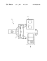
- FIG. 2 is a block diagram of a computer system having an intelligent controller in accordance with the present invention.
- FIG. 3 is a simplified flow diagram of an operation of a storage management procedure used by the computer system of FIG. 2 .
- FIGS. 2-3 there is disclosed an embodiment of an exemplary computer system 200 ( FIG. 2 ) and a storage management method 400 ( FIG. 3 ) in accordance with the present invention.
- the computer system 200 is preferably configured using a system network 202 such as a Local Area Network (LAN), a System Area Network (SAN) or a Wide Area Network (WAN).
- the system network 202 can be a high-speed communication system designed to link a workstation 204 , a server 206 and an intelligent tape controller 208 together for sharing computing resources including hardware, application programs and information.
- LAN Local Area Network
- SAN System Area Network
- WAN Wide Area Network
- the system network 202 can be a high-speed communication system designed to link a workstation 204 , a server 206 and an intelligent tape controller 208 together for sharing computing resources including hardware, application programs and information.
- the server 206 connects to a storage area network 212 using line 210 , where the storage area network is transport independent and preferably based on the Fibre Channel standard.
- the Fibre Channel standard is well known in the industry and is hereby incorporated to the fullest extent possible into this specification.
- the storage area network 212 also connects to at least one first storage unit 214 using line 216 .
- the first storage unit 214 is generally a disk drive, but may be an optical drive or a tape drive.
- the first storage unit 214 may be a library of disc drives, optical drives or tape drives.
- the first storage unit 214 operates to store data 218 including file(s) and/or image(s).
- the intelligent tape controller 208 connects to the storage area network 212 via line 220 .
- the intelligent tape controller 208 connects to at least one second storage unit 222 using line 224 .
- the second storage unit 222 is generally a tape drive, but may be a disk drive and/or an optical drive.
- the second storage unit 222 can be a library of tape drives, disc drives or optical drives.
- the first and second storage units 214 and 222 are referred to herein as the disk and tape drive, respectively.
- one aspect of the computer system 200 is to route the data 218 from the disk drive 214 through the storage area network 212 and the intelligent tape controller 208 into the tape drive 222 while bypassing the server 206 .
- the workstation 204 includes a backup application module 224 for generating and transmitting a command 226 to the server 206 .
- the server 206 and the workstation 204 including the backup application module 224 may be combined in a distributed manner to form a host 228 .
- the server 206 reads, alters (optional) and forwards to the intelligent tape controller 208 the command having information pertaining to the location(s) of the data 218 .
- the intelligent tape controller 208 operating in Peer-Mode, completes the actual Input/Output operations for routing the data 218 from the disk drive 214 to the tape drive 222 through the storage area network 212 without going through the server 206 .
- the workstation 204 and the backup application module 224 generally transmit the command 226 to the server 206 using a vendor specific protocol 227 , which is dependent upon the particular application vendor and type of server (e.g., NT, UNIX, Novell).
- the server 206 reads and transmits the command 226 a to the intelligent tape controller 208 , where the command 226 a has information as to where the data 218 is located within the first storage unit 214 (as shown) and/or the second storage unit 222 and how the data will be formatted.
- the transmitting of information containing the locations of data as compared to the data itself is referred to as “indirect data.”
- the server 206 can assure the integrity of the data 218 by holding and releasing locks on associated files being backed up while the intelligent tape controller 208 is copying the data.
- the intelligent tape controller 208 receives the command 226 a containing the locations of the data 218 via a protocol 230 .
- the protocol 230 is generally an asynchronous and pipelined protocol that permits the server 206 to queue a number of operations concurrently.
- the protocol 230 implements a set of messages 236 (e.g., operations, function calls) to form a distributed interface such that the messages can be transmitted back-and-forth between the intelligent tape controller 208 and the server 206 .
- the protocol 230 may utilize either the system network 202 or the storage area network 212 to communicate between the intelligent tape controller 208 and the server 206 .
- the protocol 230 preferably includes a normal channel 232 and a priority channel 234 on which the messages 236 , command 226 a and direct data 235 (discussed later with reference to Bridge Mode) are communicated between the server 206 and the intelligent tape controller 208 .
- the messages 236 , command 226 a and direct data 235 can be queued to either the normal channel 232 or the priority channel 234 .
- the messages 236 transmitted on the normal channel 232 are queued and executed in a predetermined order (e.g., first-in-first-out). Whereas, the messages 236 transmitted on the priority channel 234 are generally executed by the intelligent tape controller 208 or the server 206 before any new messages transmitted on the normal channel 232 are executed.
- the priority channel 234 permits control of operations while the normal channel 232 may be paused for operations such as a tape exception. In contrast, the priority channel 234 is generally not paused.
- the protocol 230 could utilize a single channel instead of the normal channel 232 and the priority channel 234 .
- the server 206 operating in Bridge Mode may transmit the direct data 235 to the intelligent tape controller 208 .
- the direct data 235 includes file(s) and/or image(s) that can be reformatted by the intelligent tape controller 208 and merged (optional) with the data 218 received by the intelligent tape controller 208 operating in Peer Mode.
- the set of messages 236 generally encompasses five types of messages including configuration and control messages 238 , write messages 240 , read messages 242 , intelligent controller initiated messages 244 and secondary storage unit positioning messages 246 .
- the messages 236 are used to perform operations that are similar to what their titles imply.
- the intelligent tape controller 208 In response to receiving any of the messages 236 , the intelligent tape controller 208 generates and transmits at least one reply message 248 back to the server 206 or host 228 . Each reply message 248 indicates whether the operation (e.g., receipt of command) has been completed.
- the configuration and control messages 238 include format operations that direct the intelligent tape controller 208 how the data 218 or the direct data 235 (if any) should be formatted as they move through the intelligent tape controller.
- the command 226 a may include format information used by the intelligent tape controller 208 to format the data 218 .
- the formatting of direct data 235 and data 218 generally occurs within the intelligent tape controller 208 but also may occur within the tape drive 222 . There are several format options available that include tape block size, padding, residual data removal, byte swapping (e.g., Big endian, Little endian), compression and encryption.
- the intelligent tape controller 208 operating in Peer Mode effectively retrieves the data 218 from the disk drive 214 and writes the retrieved data to the tape drive 222 .
- the intelligent tape controller 208 may reformat the retrieved data prior to writing the retrieved data to the tape drive 222 .
- the intelligent tape controller 208 can also be used to restore (e.g., read) data from the tape drive 222 and write the restored data to the disk drive 214 while bypassing the host 228 .
- the restoring of data from the tape drive 222 is similar to the transferring of data 218 to the tape drive, except that the transfer is in an opposite direction and different messages 236 may be used.
- the intelligent tape controller 208 can transmit acknowledgment signals (e.g., reply messages 248 ) to the host 228 .
- the acknowledgment signals can be sent to the host 228 or server 206 at various points including, for example, when data 218 is written to the tape drive 222 and when any request (e.g., command 226 a ) is received and checked for validity and security at the intelligent tape controller 208 .
- acknowledgment signals can be sent when the data 218 is received by the intelligent tape controller 208 since at this point the host 228 need not maintain a lock on the file within the disk drive 214 containing the data 218 .
- the intelligent tape controller 208 utilizes the messages 236 and protocol 230 to communicate with the host 228 .
- the host 228 is capable of performing high level error handling (e.g., fault recovery) in addition to the robotic control of the intelligent tape controller 208 .
- the storage management method 400 that may be used by the computer system 200 .
- the computer system 200 utilizes the protocol 230 (preferably) to connect the host 228 or server 206 to the intelligent controller 208 .
- the host 228 transmits the command 226 a to the intelligent tape controller 208 using the protocol 230 .
- the command 226 a can include format instructions and location information about where the data 218 is stored within the disk drive 214 .
- the format instructions are used by the intelligent tape controller 208 to format the direct data 235 (if any) or the data 218 (indirect data).
- the intelligent tape controller 208 operates to move the data 218 between the disk drive 214 and the tape drive 222 through the storage area network 212 and the intelligent tape controller while bypassing the host 228 . More specifically, the data 218 is retrieved (e.g., copied or moved) from the disk drive 214 and written to the tape drive 222 , or the data is restored from the tape drive and written to the disk drive.
- the computer system 200 can use the host 228 to transmit the direct data 235 directly to the intelligent tape controller 208 from which the direct data may be written to the disk drive 214 or the tape drive 222 .
- This type of operation has been referred to earlier as the Bridge Mode.
- the present invention provides a computer system and storage management method using an intelligent controller and storage area network for routing data between peer-level storage units while bypassing a server and workstation. Also, the computer system as disclosed frees the server from moving data through its memory and interconnects during backup or archival procedures.
Abstract
Description
Claims (36)
Priority Applications (1)
| Application Number | Priority Date | Filing Date | Title |
|---|---|---|---|
| US09/107,539 US6842833B1 (en) | 1998-06-30 | 1998-06-30 | Computer system and method for transferring data between multiple peer-level storage units |
Applications Claiming Priority (1)
| Application Number | Priority Date | Filing Date | Title |
|---|---|---|---|
| US09/107,539 US6842833B1 (en) | 1998-06-30 | 1998-06-30 | Computer system and method for transferring data between multiple peer-level storage units |
Publications (1)
| Publication Number | Publication Date |
|---|---|
| US6842833B1 true US6842833B1 (en) | 2005-01-11 |
Family
ID=33550840
Family Applications (1)
| Application Number | Title | Priority Date | Filing Date |
|---|---|---|---|
| US09/107,539 Expired - Lifetime US6842833B1 (en) | 1998-06-30 | 1998-06-30 | Computer system and method for transferring data between multiple peer-level storage units |
Country Status (1)
| Country | Link |
|---|---|
| US (1) | US6842833B1 (en) |
Cited By (26)
| Publication number | Priority date | Publication date | Assignee | Title |
|---|---|---|---|---|
| US20030041177A1 (en) * | 2000-02-29 | 2003-02-27 | Thomas Warschko | Method for controlling the communication of individual computers in a multicomputer system |
| US20030191734A1 (en) * | 2002-04-04 | 2003-10-09 | Voigt Douglas L. | Method and program product for managing data access routes in a data storage system providing multiple access routes |
| US20050160243A1 (en) * | 2001-06-01 | 2005-07-21 | Lubbers Clark E. | Point in time storage copy |
| US20050203874A1 (en) * | 2001-10-22 | 2005-09-15 | Lubbers Clark E. | Multi-controller data processing |
| US20050229021A1 (en) * | 2002-03-28 | 2005-10-13 | Clark Lubbers | Automatic site failover |
| US20050243611A1 (en) * | 2002-03-26 | 2005-11-03 | Clark Lubbers | Flexible data replication mechanism |
| US20050262298A1 (en) * | 2002-03-26 | 2005-11-24 | Clark Lubbers | System and method for ensuring merge completion in a storage area network |
| US20060080500A1 (en) * | 2004-10-07 | 2006-04-13 | Unisys Corporation | Method and system for managing data transfer between different types of tape media |
| US20060168403A1 (en) * | 2005-01-27 | 2006-07-27 | Curt Kolovson | Intelligent cache management |
| US20060171055A1 (en) * | 2005-01-31 | 2006-08-03 | Ballard Curtis C | Recording errors in tape drives |
| US20060230243A1 (en) * | 2005-04-06 | 2006-10-12 | Robert Cochran | Cascaded snapshots |
| US20070022263A1 (en) * | 2005-07-22 | 2007-01-25 | John Fandel | Data synchronization management |
| US20070025008A1 (en) * | 2005-07-27 | 2007-02-01 | Ballard Curtis C | Tape drive error management |
| US20070094393A1 (en) * | 2005-10-24 | 2007-04-26 | Cochran Robert A | Intelligent logical unit provisioning |
| US7353353B2 (en) | 2001-01-17 | 2008-04-01 | Hewlett-Packard Development Company, L.P. | File security management |
| US20080178188A1 (en) * | 2007-01-19 | 2008-07-24 | Thomas Cooke | Critical resource management |
| US20080215806A1 (en) * | 2007-03-01 | 2008-09-04 | Feather Stanley S | Access control management |
| US20080212222A1 (en) * | 2007-03-01 | 2008-09-04 | Stan Feather | Access control management |
| US7467268B2 (en) | 2006-04-14 | 2008-12-16 | Hewlett-Packard Development Company, L.P. | Concurrent data restore and background copy operations in storage networks |
| US7496539B1 (en) * | 2008-05-15 | 2009-02-24 | International Business Machines Corporation | Systems, methods and computer products for providing tape library dynamic price performance enhancement feature |
| US7694079B2 (en) | 2007-04-04 | 2010-04-06 | Hewlett-Packard Development Company, L.P. | Tagged sequential read operations |
| US7831788B1 (en) * | 2001-08-07 | 2010-11-09 | Symantec Operating Corporation | System and method using locks for providing safe movement of data using third party copy techniques |
| US20100293329A1 (en) * | 2009-05-13 | 2010-11-18 | Computer Associates Think, Inc. | Multi-stream restore system and method |
| US20110029963A1 (en) * | 2009-07-31 | 2011-02-03 | Rick Smith | System and method for deploying software into a computing environment |
| US8145861B1 (en) * | 2005-10-17 | 2012-03-27 | Unisys Corporation | Managing data transfer between different types of tape media with encryption |
| CN101640695B (en) * | 2008-07-29 | 2012-08-08 | 英业达股份有限公司 | Method for providing customization replies by using disk array |
Citations (5)
| Publication number | Priority date | Publication date | Assignee | Title |
|---|---|---|---|---|
| US5537585A (en) * | 1994-02-25 | 1996-07-16 | Avail Systems Corporation | Data storage management for network interconnected processors |
| US5586250A (en) * | 1993-11-12 | 1996-12-17 | Conner Peripherals, Inc. | SCSI-coupled module for monitoring and controlling SCSI-coupled raid bank and bank environment |
| US6000020A (en) * | 1997-04-01 | 1999-12-07 | Gadzoox Networks, Inc. | Hierarchical storage management from a mirrored file system on a storage network segmented by a bridge |
| US6023709A (en) * | 1997-12-15 | 2000-02-08 | International Business Machines Corporation | Automated file error classification and correction in a hierarchical storage management system |
| US6173377B1 (en) * | 1993-04-23 | 2001-01-09 | Emc Corporation | Remote data mirroring |
-
1998
- 1998-06-30 US US09/107,539 patent/US6842833B1/en not_active Expired - Lifetime
Patent Citations (6)
| Publication number | Priority date | Publication date | Assignee | Title |
|---|---|---|---|---|
| US6173377B1 (en) * | 1993-04-23 | 2001-01-09 | Emc Corporation | Remote data mirroring |
| US5586250A (en) * | 1993-11-12 | 1996-12-17 | Conner Peripherals, Inc. | SCSI-coupled module for monitoring and controlling SCSI-coupled raid bank and bank environment |
| US5537585A (en) * | 1994-02-25 | 1996-07-16 | Avail Systems Corporation | Data storage management for network interconnected processors |
| US5832522A (en) * | 1994-02-25 | 1998-11-03 | Kodak Limited | Data storage management for network interconnected processors |
| US6000020A (en) * | 1997-04-01 | 1999-12-07 | Gadzoox Networks, Inc. | Hierarchical storage management from a mirrored file system on a storage network segmented by a bridge |
| US6023709A (en) * | 1997-12-15 | 2000-02-08 | International Business Machines Corporation | Automated file error classification and correction in a hierarchical storage management system |
Cited By (44)
| Publication number | Priority date | Publication date | Assignee | Title |
|---|---|---|---|---|
| US7308509B2 (en) * | 2000-02-29 | 2007-12-11 | Partec Ag | Method for controlling the communication of single computers in a computer network |
| US20030041177A1 (en) * | 2000-02-29 | 2003-02-27 | Thomas Warschko | Method for controlling the communication of individual computers in a multicomputer system |
| US7353353B2 (en) | 2001-01-17 | 2008-04-01 | Hewlett-Packard Development Company, L.P. | File security management |
| US20050160243A1 (en) * | 2001-06-01 | 2005-07-21 | Lubbers Clark E. | Point in time storage copy |
| US7290102B2 (en) | 2001-06-01 | 2007-10-30 | Hewlett-Packard Development Company, L.P. | Point in time storage copy |
| US7831788B1 (en) * | 2001-08-07 | 2010-11-09 | Symantec Operating Corporation | System and method using locks for providing safe movement of data using third party copy techniques |
| US7478215B2 (en) | 2001-10-22 | 2009-01-13 | Hewlett-Packard Development Company, L.P. | Multi-controller write operations |
| US20050203874A1 (en) * | 2001-10-22 | 2005-09-15 | Lubbers Clark E. | Multi-controller data processing |
| US20050262298A1 (en) * | 2002-03-26 | 2005-11-24 | Clark Lubbers | System and method for ensuring merge completion in a storage area network |
| US20050243611A1 (en) * | 2002-03-26 | 2005-11-03 | Clark Lubbers | Flexible data replication mechanism |
| US7137032B2 (en) | 2002-03-26 | 2006-11-14 | Hewlett-Packard Development Company, L.P. | System and method for ensuring merge completion in a storage area network |
| US7542987B2 (en) | 2002-03-28 | 2009-06-02 | Hewlett-Packard Development Company, L.P. | Automatic site failover |
| US20050229021A1 (en) * | 2002-03-28 | 2005-10-13 | Clark Lubbers | Automatic site failover |
| US7171396B2 (en) * | 2002-04-04 | 2007-01-30 | Hewlett-Packard Development Company, L.P. | Method and program product for specifying the different data access route for the first data set includes storing an indication of the different access for the first data set providing alternative data access routes to a data storage |
| US20030191734A1 (en) * | 2002-04-04 | 2003-10-09 | Voigt Douglas L. | Method and program product for managing data access routes in a data storage system providing multiple access routes |
| US20060080500A1 (en) * | 2004-10-07 | 2006-04-13 | Unisys Corporation | Method and system for managing data transfer between different types of tape media |
| WO2006041750A3 (en) * | 2004-10-07 | 2007-04-05 | Unisys Corp | Method and system for managing data transfer between different types of tape media |
| US8127088B2 (en) | 2005-01-27 | 2012-02-28 | Hewlett-Packard Development Company, L.P. | Intelligent cache management |
| US20060168403A1 (en) * | 2005-01-27 | 2006-07-27 | Curt Kolovson | Intelligent cache management |
| US7301718B2 (en) | 2005-01-31 | 2007-11-27 | Hewlett-Packard Development Company, L.P. | Recording errors in tape drives |
| US20060171055A1 (en) * | 2005-01-31 | 2006-08-03 | Ballard Curtis C | Recording errors in tape drives |
| US20060230243A1 (en) * | 2005-04-06 | 2006-10-12 | Robert Cochran | Cascaded snapshots |
| US20070022263A1 (en) * | 2005-07-22 | 2007-01-25 | John Fandel | Data synchronization management |
| US7779218B2 (en) | 2005-07-22 | 2010-08-17 | Hewlett-Packard Development Company, L.P. | Data synchronization management |
| US7206156B2 (en) | 2005-07-27 | 2007-04-17 | Hewlett-Packard Development Company, L.P. | Tape drive error management |
| US20070025008A1 (en) * | 2005-07-27 | 2007-02-01 | Ballard Curtis C | Tape drive error management |
| US8145861B1 (en) * | 2005-10-17 | 2012-03-27 | Unisys Corporation | Managing data transfer between different types of tape media with encryption |
| US20070094393A1 (en) * | 2005-10-24 | 2007-04-26 | Cochran Robert A | Intelligent logical unit provisioning |
| US7721053B2 (en) | 2005-10-24 | 2010-05-18 | Hewlett-Packard Development Company, L.P. | Intelligent logical unit provisioning |
| US7467268B2 (en) | 2006-04-14 | 2008-12-16 | Hewlett-Packard Development Company, L.P. | Concurrent data restore and background copy operations in storage networks |
| US20080178188A1 (en) * | 2007-01-19 | 2008-07-24 | Thomas Cooke | Critical resource management |
| US7934027B2 (en) | 2007-01-19 | 2011-04-26 | Hewlett-Packard Development Company, L.P. | Critical resource management |
| US8024514B2 (en) | 2007-03-01 | 2011-09-20 | Hewlett-Packard Development Company, L.P. | Access control management |
| US7861031B2 (en) | 2007-03-01 | 2010-12-28 | Hewlett-Packard Development Company, L.P. | Access control management |
| US20080212222A1 (en) * | 2007-03-01 | 2008-09-04 | Stan Feather | Access control management |
| US20080215806A1 (en) * | 2007-03-01 | 2008-09-04 | Feather Stanley S | Access control management |
| US7694079B2 (en) | 2007-04-04 | 2010-04-06 | Hewlett-Packard Development Company, L.P. | Tagged sequential read operations |
| US7496539B1 (en) * | 2008-05-15 | 2009-02-24 | International Business Machines Corporation | Systems, methods and computer products for providing tape library dynamic price performance enhancement feature |
| CN101640695B (en) * | 2008-07-29 | 2012-08-08 | 英业达股份有限公司 | Method for providing customization replies by using disk array |
| US20100293329A1 (en) * | 2009-05-13 | 2010-11-18 | Computer Associates Think, Inc. | Multi-stream restore system and method |
| US8161233B2 (en) * | 2009-05-13 | 2012-04-17 | Computer Associates Think, Inc. | Multi-stream restore system and method |
| US20110029963A1 (en) * | 2009-07-31 | 2011-02-03 | Rick Smith | System and method for deploying software into a computing environment |
| US9182964B2 (en) | 2009-07-31 | 2015-11-10 | Hewlett-Packard Development Company, L.P. | System and method for deploying software into a computing environment |
| US9864592B2 (en) | 2009-07-31 | 2018-01-09 | Entit Software Llc | System and method for deploying software into a computing environment |
Similar Documents
| Publication | Publication Date | Title |
|---|---|---|
| US6842833B1 (en) | Computer system and method for transferring data between multiple peer-level storage units | |
| US7581077B2 (en) | Method and system for transferring data in a storage operation | |
| US6363462B1 (en) | Storage controller providing automatic retention and deletion of synchronous back-up data | |
| US8055870B2 (en) | Tape storage emulation for open systems environments | |
| US6529976B1 (en) | Heterogeneous computer system, heterogeneous input output system and data back-up method for the systems | |
| US6535967B1 (en) | Method and apparatus for transferring data between a primary storage system and a secondary storage system using a bridge volume | |
| US7496718B2 (en) | Data transfer and access control between disk array systems | |
| US7020731B2 (en) | Disk array control device with two different internal connection systems | |
| US7971011B2 (en) | Remote copy method and storage system | |
| US6157962A (en) | Multipath I/O storage systems with multiipath I/O request mechanisms | |
| US7209972B1 (en) | High speed data transfer mechanism | |
| EP1100001B1 (en) | Storage system supporting file-level and block-level accesses | |
| US7200697B1 (en) | High speed data transfer between mainframe storage systems | |
| US6453396B1 (en) | System, method and computer program product for hardware assisted backup for a computer mass storage system | |
| US11106605B2 (en) | Enhanced tape drive communication | |
| JP2000163301A (en) | Method, device, and system for file synchronization for fault-tolerant network | |
| EP1122924B1 (en) | Method and apparatus for providing local path I/O in a distributed file system | |
| US6718402B1 (en) | Method and system for persistent unit attention in a fibre channel storage router | |
| JP4997784B2 (en) | Data storage system, data storage method, and data storage program | |
| US6289422B2 (en) | System for multi-volume, write-behind data storage in a distributed processing system | |
| US20200334180A1 (en) | Automated transformation from command mode to transport mode | |
| US6360304B1 (en) | Method for multi-volume, write-behind data storage in a distributed processing system | |
| JPH1040205A (en) | Connection control system between central processing unit and input/output device |
Legal Events
| Date | Code | Title | Description |
|---|---|---|---|
| AS | Assignment |
Owner name: COMPAQ COMPUTER CORPORATION, TEXAS Free format text: ASSIGNMENT OF ASSIGNORS INTEREST;ASSIGNORS:PHILLIPS, GARY L.;GREADY, ROBERT S.;RITTER, RAYMOND A.;AND OTHERS;REEL/FRAME:009469/0172;SIGNING DATES FROM 19980904 TO 19980914 |
|
| AS | Assignment |
Owner name: COMPAQ INFORMATION TECHNOLOGIES GROUP, L.P., TEXAS Free format text: ASSIGNMENT OF ASSIGNORS INTEREST;ASSIGNOR:COMPAQ COMPUTER CORPORATION;REEL/FRAME:012372/0522 Effective date: 20010620 |
|
| AS | Assignment |
Owner name: HEWLETT-PACKARD DEVELOPMENT COMPANY, L.P., TEXAS Free format text: CHANGE OF NAME;ASSIGNOR:COMPAQ INFORMATION TECHNOLOGIES GROUP L.P.;REEL/FRAME:014177/0428 Effective date: 20021001 Owner name: HEWLETT-PACKARD DEVELOPMENT COMPANY, L.P.,TEXAS Free format text: CHANGE OF NAME;ASSIGNOR:COMPAQ INFORMATION TECHNOLOGIES GROUP L.P.;REEL/FRAME:014177/0428 Effective date: 20021001 |
|
| STCF | Information on status: patent grant |
Free format text: PATENTED CASE |
|
| FPAY | Fee payment |
Year of fee payment: 4 |
|
| FPAY | Fee payment |
Year of fee payment: 8 |
|
| AS | Assignment |
Owner name: HEWLETT PACKARD ENTERPRISE DEVELOPMENT LP, TEXAS Free format text: ASSIGNMENT OF ASSIGNORS INTEREST;ASSIGNOR:HEWLETT-PACKARD DEVELOPMENT COMPANY, L.P.;REEL/FRAME:037079/0001 Effective date: 20151027 |
|
| FPAY | Fee payment |
Year of fee payment: 12 |
|
| SULP | Surcharge for late payment |
Year of fee payment: 11 |
|
| AS | Assignment |
Owner name: OT PATENT ESCROW, LLC, ILLINOIS Free format text: PATENT ASSIGNMENT, SECURITY INTEREST, AND LIEN AGREEMENT;ASSIGNORS:HEWLETT PACKARD ENTERPRISE DEVELOPMENT LP;HEWLETT PACKARD ENTERPRISE COMPANY;REEL/FRAME:055269/0001 Effective date: 20210115 |
|
| AS | Assignment |
Owner name: VALTRUS INNOVATIONS LIMITED, IRELAND Free format text: ASSIGNMENT OF ASSIGNORS INTEREST;ASSIGNOR:OT PATENT ESCROW, LLC;REEL/FRAME:061244/0298 Effective date: 20220803 |