US6856236B2 - RF home automation system comprising nodes with dual functionality - Google Patents

RF home automation system comprising nodes with dual functionality Download PDF

Info

Publication number
US6856236B2
US6856236B2 US09/841,050 US84105001A US6856236B2 US 6856236 B2 US6856236 B2 US 6856236B2 US 84105001 A US84105001 A US 84105001A US 6856236 B2 US6856236 B2 US 6856236B2
Authority
US
United States
Prior art keywords
devices
signal
controller
identifiers
destination
Prior art date
Legal status (The legal status is an assumption and is not a legal conclusion. Google has not performed a legal analysis and makes no representation as to the accuracy of the status listed.)
Expired - Lifetime, expires
Application number
US09/841,050
Other versions
US20020044042A1 (en
Inventor
Carlos Mélia Christensen
Jesper Knudsen
Current Assignee (The listed assignees may be inaccurate. Google has not performed a legal analysis and makes no representation or warranty as to the accuracy of the list.)
Ensys AS
Silicon Laboratories Inc
Original Assignee
Ensys AS
Priority date (The priority date is an assumption and is not a legal conclusion. Google has not performed a legal analysis and makes no representation as to the accuracy of the date listed.)
Filing date
Publication date
Family has litigation
First worldwide family litigation filed litigation Critical https://patents.darts-ip.com/?family=24183157&utm_source=google_patent&utm_medium=platform_link&utm_campaign=public_patent_search&patent=US6856236(B2) "Global patent litigation dataset” by Darts-ip is licensed under a Creative Commons Attribution 4.0 International License.
Application filed by Ensys AS filed Critical Ensys AS
Priority to US09/841,050 priority Critical patent/US6856236B2/en
Assigned to ZENSYS A/S reassignment ZENSYS A/S ASSIGNMENT OF ASSIGNORS INTEREST (SEE DOCUMENT FOR DETAILS). Assignors: CHRISTENSEN, CARLOS MELIA, KNUDSEN, JESPER
Publication of US20020044042A1 publication Critical patent/US20020044042A1/en
Application granted granted Critical
Publication of US6856236B2 publication Critical patent/US6856236B2/en
Assigned to SIGMA DESIGNS, INC. reassignment SIGMA DESIGNS, INC. ASSIGNMENT OF ASSIGNORS INTEREST (SEE DOCUMENT FOR DETAILS). Assignors: ZENSYS A/S
Assigned to SILICON LABORATORIES INC. reassignment SILICON LABORATORIES INC. ASSIGNMENT OF ASSIGNORS INTEREST (SEE DOCUMENT FOR DETAILS). Assignors: SIGMA DESIGNS, INC.
Adjusted expiration legal-status Critical
Expired - Lifetime legal-status Critical Current

Links

Images

Classifications

    • GPHYSICS
    • G05CONTROLLING; REGULATING
    • G05BCONTROL OR REGULATING SYSTEMS IN GENERAL; FUNCTIONAL ELEMENTS OF SUCH SYSTEMS; MONITORING OR TESTING ARRANGEMENTS FOR SUCH SYSTEMS OR ELEMENTS
    • G05B15/00Systems controlled by a computer
    • G05B15/02Systems controlled by a computer electric
    • GPHYSICS
    • G05CONTROLLING; REGULATING
    • G05BCONTROL OR REGULATING SYSTEMS IN GENERAL; FUNCTIONAL ELEMENTS OF SUCH SYSTEMS; MONITORING OR TESTING ARRANGEMENTS FOR SUCH SYSTEMS OR ELEMENTS
    • G05B19/00Programme-control systems
    • G05B19/02Programme-control systems electric
    • G05B19/04Programme control other than numerical control, i.e. in sequence controllers or logic controllers
    • G05B19/042Programme control other than numerical control, i.e. in sequence controllers or logic controllers using digital processors
    • G05B19/0426Programming the control sequence
    • HELECTRICITY
    • H04ELECTRIC COMMUNICATION TECHNIQUE
    • H04BTRANSMISSION
    • H04B7/00Radio transmission systems, i.e. using radiation field
    • H04B7/14Relay systems
    • H04B7/15Active relay systems
    • H04B7/155Ground-based stations
    • H04B7/15507Relay station based processing for cell extension or control of coverage area
    • GPHYSICS
    • G05CONTROLLING; REGULATING
    • G05BCONTROL OR REGULATING SYSTEMS IN GENERAL; FUNCTIONAL ELEMENTS OF SUCH SYSTEMS; MONITORING OR TESTING ARRANGEMENTS FOR SUCH SYSTEMS OR ELEMENTS
    • G05B2219/00Program-control systems
    • G05B2219/20Pc systems
    • G05B2219/21Pc I-O input output
    • G05B2219/21042Address a group, a zone
    • GPHYSICS
    • G05CONTROLLING; REGULATING
    • G05BCONTROL OR REGULATING SYSTEMS IN GENERAL; FUNCTIONAL ELEMENTS OF SUCH SYSTEMS; MONITORING OR TESTING ARRANGEMENTS FOR SUCH SYSTEMS OR ELEMENTS
    • G05B2219/00Program-control systems
    • G05B2219/20Pc systems
    • G05B2219/21Pc I-O input output
    • G05B2219/21073Each module has push button, trigger circuit to initialise address setting
    • GPHYSICS
    • G05CONTROLLING; REGULATING
    • G05BCONTROL OR REGULATING SYSTEMS IN GENERAL; FUNCTIONAL ELEMENTS OF SUCH SYSTEMS; MONITORING OR TESTING ARRANGEMENTS FOR SUCH SYSTEMS OR ELEMENTS
    • G05B2219/00Program-control systems
    • G05B2219/20Pc systems
    • G05B2219/25Pc structure of the system
    • G05B2219/25081Clone, copy configuration from first device, in teach mode, to second identical device
    • GPHYSICS
    • G05CONTROLLING; REGULATING
    • G05BCONTROL OR REGULATING SYSTEMS IN GENERAL; FUNCTIONAL ELEMENTS OF SUCH SYSTEMS; MONITORING OR TESTING ARRANGEMENTS FOR SUCH SYSTEMS OR ELEMENTS
    • G05B2219/00Program-control systems
    • G05B2219/20Pc systems
    • G05B2219/25Pc structure of the system
    • G05B2219/25181Repeater
    • GPHYSICS
    • G05CONTROLLING; REGULATING
    • G05BCONTROL OR REGULATING SYSTEMS IN GENERAL; FUNCTIONAL ELEMENTS OF SUCH SYSTEMS; MONITORING OR TESTING ARRANGEMENTS FOR SUCH SYSTEMS OR ELEMENTS
    • G05B2219/00Program-control systems
    • G05B2219/20Pc systems
    • G05B2219/25Pc structure of the system
    • G05B2219/25196Radio link, transponder
    • GPHYSICS
    • G05CONTROLLING; REGULATING
    • G05BCONTROL OR REGULATING SYSTEMS IN GENERAL; FUNCTIONAL ELEMENTS OF SUCH SYSTEMS; MONITORING OR TESTING ARRANGEMENTS FOR SUCH SYSTEMS OR ELEMENTS
    • G05B2219/00Program-control systems
    • G05B2219/20Pc systems
    • G05B2219/25Pc structure of the system
    • G05B2219/25208Control message, address and command portion
    • GPHYSICS
    • G05CONTROLLING; REGULATING
    • G05BCONTROL OR REGULATING SYSTEMS IN GENERAL; FUNCTIONAL ELEMENTS OF SUCH SYSTEMS; MONITORING OR TESTING ARRANGEMENTS FOR SUCH SYSTEMS OR ELEMENTS
    • G05B2219/00Program-control systems
    • G05B2219/20Pc systems
    • G05B2219/25Pc structure of the system
    • G05B2219/25211Broadcast mode, length message, command, address of originator and destination
    • GPHYSICS
    • G05CONTROLLING; REGULATING
    • G05BCONTROL OR REGULATING SYSTEMS IN GENERAL; FUNCTIONAL ELEMENTS OF SUCH SYSTEMS; MONITORING OR TESTING ARRANGEMENTS FOR SUCH SYSTEMS OR ELEMENTS
    • G05B2219/00Program-control systems
    • G05B2219/20Pc systems
    • G05B2219/26Pc applications
    • G05B2219/2642Domotique, domestic, home control, automation, smart house
    • GPHYSICS
    • G05CONTROLLING; REGULATING
    • G05BCONTROL OR REGULATING SYSTEMS IN GENERAL; FUNCTIONAL ELEMENTS OF SUCH SYSTEMS; MONITORING OR TESTING ARRANGEMENTS FOR SUCH SYSTEMS OR ELEMENTS
    • G05B2219/00Program-control systems
    • G05B2219/30Nc systems
    • G05B2219/32Operator till task planning
    • G05B2219/32234Maintenance planning
    • GPHYSICS
    • G05CONTROLLING; REGULATING
    • G05BCONTROL OR REGULATING SYSTEMS IN GENERAL; FUNCTIONAL ELEMENTS OF SUCH SYSTEMS; MONITORING OR TESTING ARRANGEMENTS FOR SUCH SYSTEMS OR ELEMENTS
    • G05B2219/00Program-control systems
    • G05B2219/30Nc systems
    • G05B2219/37Measurements
    • G05B2219/37252Life of tool, service life, decay, wear estimation

Definitions

  • the present invention relates to a wireless home automation system having a controller for controlling a broad variety of functions via two ways communication with a plurality of devices. More specifically, the invention relates to a new and flexible way of establishing a wireless network by using devices which functions as both input/output devices and repeaters. By establishing an even distribution of these dual-functionality devices, the user can reach any device without use of dedicated repeater stations.
  • I/O input/output
  • Such systems are constructed as networks with a plurality of nodes which can be controllers, I/O devices, or dedicated signal repeaters or amplifiers.
  • wired networks generally provide a better quality
  • wireless networks have become more and more popular as a cheap and easy accessible network solution.
  • Wireless networks clearly overcome the above-mentioned drawbacks of wired networks.
  • most existing low cost wireless automation systems have a low quality in most of the mentioned parameters.
  • Higher bandwidth wireless automation systems are typically very complex and require higher processing power whereby the price get close to the price for a wired network.
  • U.S. Pat. No. 5,905,442 discloses a wireless automation system with a centralized remote control which controls I/O devices for providing electrical power to appliances from power outlets of the power mains in building.
  • the remote control and I/O devices comprise RF transceivers, and the system includes dedicated repeater units for repeating signals to I/O devices out of the range of the remote control.
  • U.S. Pat. No. 5,875,179 describes a method for synchronising communications over a backbone architecture in a wireless network.
  • the system invokes two controllers, one of which is a master and another which is an alternate master which will be activated only when the master is out of work.
  • Dedicated repeaters and I/O devices in the system are commonly designated as nodes, however, it is clear from the context that there is distinct functional difference between repeater nodes and end (I/O) nodes.
  • U.S. Pat. No. 4,427,968 discloses a wireless automation system with flexible message routing.
  • a central station produces a signal for a I/O device, the signal contains a route code, an address code, an identifying code and a message code.
  • Dedicated repeaters in the architecture receive the signals and follow a specified procedure for repeating signal. Repeaters may also be addressed as end nodes, e.g. in order for the controller to download routing tables.
  • U.S. Pat. No. 4,250,489 describes a communication system having dedicated repeaters organised in a pyramidal configuration.
  • the repeaters are bidirectionally addressable and may receive interrogation signals telling a repeater that it is the last repeater in the chain.
  • the repeaters are not connected to appliances and do not perform any functions besides repeating and routing signals.
  • the present invention provides a high quality, low cost wireless automation system using radio frequency (RF) signals.
  • the system according to the present invention preferably operates at bandwidth dedicated for control commands i.e. a bandwidth around 10 kbps.
  • bandwidth dedicated for control commands i.e. a bandwidth around 10 kbps.
  • Such a low bandwidth allows for chips which can be mass produced at lower prices than chips for large bandwidth systems.
  • RF transmitters and receivers of the system preferably operate within a “public” frequency range wherein a license is not required, thereby further reducing cost.
  • the system according to the present invention is optimized to ensure a high reliability, range/coverage, versatility, and flexibility.
  • the system according to the present invention provides a system having a new and inventive routing architecture for wireless networks which allows for much more complete and flexible routing schemes when compared to the systems of the prior art.
  • the invention provides an automation system for controlling and monitoring devices comprising:
  • one or more of the plurality of devices are further adapted to act as signal repeating devices in that the processors of each of said one or more devices comprises means for, upon reception of a first signal, processing said information in its processor if one of the one or more destination identifiers corresponds to the device identifier of the device, and means for, upon reception of a first signal, transmitting a second signal holding at least said destination identifier and said information if one of the one or more repeater identifiers correspond to the device identifier of the device.
  • a first signal is preferably a signal comprising:
  • the processors of each of the plurality of devices also comprise means for generating a first signal comprising one or more destination identifiers, information related to the operation of the appliance connected the device, and repeater identifiers.
  • the first aspect of the present invention provides one or more devices having a dual functionality in that they can act as I/O devices as well as repeaters.
  • the signal range of a transmitter is the physical range within which a device/controller will receive a signal addressed for that device/controller when the signal is transmitted from the transmitter.
  • the device When a device receives a signal carrying information and designating the device's identifier as a repeater identifier, the device will repeat the signal, that is, transmit a signal carrying at least part of the information also carried by the received signal.
  • devices or controllers within the signal range of the repeating device, but outside the signal range of the original transmitter can receive the signal transmitted by the repeating device.
  • all devices in a system can act as repeating devices.
  • the system can build a routing table held in the second memory of the first controller, the routing table indicating, for each device, other devices which can receive and process a signal transmitted by said device and vice versa.
  • the processor of the first controller preferably comprises means for identifying, in the routing table, device identifiers of devices for repeating a first signal having a predetermined destination identifier, and to include said device identifiers as repeater identifiers in the first signal.
  • the system is preferably adapted to designate devices to be repeaters on a provisional basis.
  • each controller comprises a program for systematically designating device to act as repeating devices.
  • the program also builds a data table comprising the identifiers of the devices designated as repeaters and the identifiers of at least some of the devices, which are within the signal range of each repeater.
  • Devices will be repeaters only on a provisional basis, since the controller may remove the device identifier of a repeating device from the repeater table at any time, e.g. when located in another position in the network.
  • the program builds a data table comprising the identifiers of all devices controlled by the first controller, and the identifier of the one or more repeaters, which must be used in order to reach each device.
  • the devices establishes a network which can reach all devices in the system.
  • a device or a group of devices it may be necessary to include one or more devices between the remaining system and the remote device/group with the sole purpose of repeating signals to the remote device/group.
  • the inserted devices may of course be connected to an appliance and function also as normal input/output devices later on.
  • the minimum density of devices should be adjusted to the average range of the transmitters, which, however, depends strongly upon the environment.
  • processor designates any conventional or proprietary processor or microprocessor such as a hardwired proprietary processor or finite state machine, Read Only Memory (ROM) or software programmable microprocessor as well as combinations thereof capable of providing the required management of received and transmitted data.
  • processor designates any conventional or proprietary processor or microprocessor such as a hardwired proprietary processor or finite state machine, Read Only Memory (ROM) or software programmable microprocessor as well as combinations thereof capable of providing the required management of received and transmitted data.
  • memory designates one or several memory areas adapted to store digital information. Preferably, it is possible to read, write and delete data in the memory.
  • the memory might be allocated in a larger memory structure comprising several memories utilized by a processor for e.g. application program storage and/or data storage.
  • the term “signal” designates a conveyor of information, such as a series of pulses of electromagnetic (RF) radiation.
  • the signal is formed by a modulation of a carrier waveform and recovered during reception by demodulation.
  • the modulations may be digital modulations so as to convey digital information.
  • the information in a signal according to the present invention is preferably comprised in a digital communication frame, which comprises a number of bits identifying the frame and a number of bits conveying the transmitted information or data.
  • An identifier is a data string identifying a controller or a device or part of a device. Also, an identifier may identify a data structure such as a table or dedicated memory area. An identifier may be a name, a code or a number.
  • Controller and device identifiers are data strings identifying the individual controller or device as single, specific controller or devices within a network. Controller or device identifiers are preferably used to address the specific controller or device in communication within a network. Preferably, the controller or device identifiers are used to designate the specific controller or device within a communication protocol, which is an agreed set of operational procedures to enable data to be transferred between controller and devices.
  • a unique identifier is a data string identifying a single, specific controller or device wherein the data string is not identical to any data string used to identify any other specific controller or device. A unique identifier is preferably set during fabrication.
  • a network is preferably characterized by a unique system identifier, which is used in all communication within the system.
  • identifiers for controllers and devices comprise a first and a second part, wherein the first part is the unique system identifier and the second part is the identifier for each specific controller or device within the system.
  • the two-part identifier identifying a controller or device is unique if the system identifier is unique.
  • the controllers does have unique identifiers set during fabrication, and the processor of the first controller implemented in the system is adapted to make its unique identifier the unique system identifier.
  • all controllers and devices in the system have a unique identifier so that no two controllers or devices are addressed identically.
  • the processor of a controller is adapted to generate signals comprising at least one device identifier and at least one predetermined setting held in relation to said device identifier.
  • the first processor is adapted to generate a signal comprising commands for devices and addressing the signal to one or more devices.
  • a command is a code, word or phrase to which the receiving processor responds in a predetermined way.
  • a respond is any action carried out by the controller or device initiated by the reception of the command.
  • signals comprising commands for devices may be addressed to all devices without addressing each device individually, instead a general designation to which all signals are adapted to respond is used. Such signals are referred to as broadcast signals.
  • the devices further comprise a status setting for determining whether the device should respond to commands in a broadcast signal addressed to all devices.
  • the first device of the system according to the present invention may be an output device in that it is adapted to generate an output in response to a received signal.
  • the output generated by the first device is adjusted in response to a signal transmitted from the first controller.
  • the user can control the output from the first device.
  • the output is a signal to an appliance operationally connected to the first device, and comprises one or more instructions related to the operational state of the appliance.
  • the appliance connected to an output device may be integrated with the output device so that the appliance and the output device form parts of the same unit. Thereby the user may control the operation of the appliance by controlling the first device. Hence the user may operate the appliance remotely.
  • the output from the first device is electric power in the form of electric current or an electric potential.
  • the first device may adjust the output power to a level corresponding to a setting comprised in a received signal, that is, the user may turn the output on or off or adjust the output level to any desired power.
  • the user can restrict the operation and hence the output from the first device, and protect this restriction by a requiring code or a predetermined action before removing the restriction. Thereby, the user can prohibit other users from changing the operational state of the device.
  • the restriction may also be a fixed operational state of the device. This may be e.g. an “off” state where the device provides no output, a state where the device provides a certain type of output such as a certain signal to an appliance connected to the output, a state where the output is allowed to be adjusted only within a predetermined range or within a predetermined time or both, a state where the output is adjusted according to a predetermined program, etc.
  • the first device restricts the output in response to a received first set of instructions, and the restriction may only be removed in response to either a received second set of instructions or a code or predetermined action given directly to the device by the user.
  • the first controller is preferably adapted to generate the second set of instructions only when provided with the predetermined code, password or alike.
  • the first device is adapted to receive an input from the appliance connected thereto:
  • the processor of a device is preferably adapted to, in response to the received input, generate and transmit a first signal to a controller or to another device.
  • the appliance connected to an input device may be integrated with the input device so that the appliance and the input device form parts of the same unit.
  • the appliance operationally connected to the input device is a sensor, and the sensor, upon sensing a signal, forms a signal, which is received by the processor of the input device as an input.
  • the signal from the sensor is an electric signal.
  • the processor may process the received input, e.g. store the input in the second memory of the first device, generated and transmit a signal comprising the input, store the input in the second memory of the first device and at a later time generate and transmit a signal comprising the input, generate and transmit a signal in response to the received input, etc.
  • the first sensor may be any sensor selected from the group consisting of electromagnetic radiation sensor, luminosity sensor, moisture sensor, movement sensor, temperature sensor, mechanical actuator contact, sound sensor, pressure sensor, electric signal sensor, smoke detector, audio pattern recognizing means, visual pattern recognizing means, molecular composition analyzing means and more as well as any combinations thereof.
  • the senor measures the impedance of an electric signal, such as the capacitance, the resistance or the inductance.
  • the system according to the present invention preferably comprises a protocol.
  • a protocol is any set of operational procedures, which enable data such as identifiers, settings and frames and any data comprised in a frame as well as stored data to be transferred and administered within the system.
  • the means for generating a first signal, and various means comprised in these means are typically programs or routines forming part of the protocol.
  • it is the protocol of the transmitting controller/device which generates frames to be transmitted in a signal.
  • Such frame preferably designates the system, the source controller/device and the destination controller/device by their identifiers, and one or more signal repeating devices by their identifiers.
  • the protocol includes the commands, information or data transferred by the frame.
  • it is preferably the protocol in the receiving part, which reads the received frame and enables the receiving part to respond to the signal.
  • the system protocol preferably comprises operational procedures for masking the identifiers of devices addressed by a frame.
  • the making procedure is an operation that builds a register with each entry corresponding to a device, and where the value of each entry indicates whether the corresponding devices should respond to a command in the frame or not. Instead of including all the identifiers for the devices that should respond to a command in a frame one includes the masking register, whereby a shorthand designation of devices is achieved.
  • the system protocol preferably comprises operational procedures for generating a first type of frame comprising one or more commands.
  • the protocol comprising a procedure of masking a first group of device identifiers in a table of a controller in order to generate a string of bits forming part of the frame, so that each bit corresponds to a device identifier and a device of the first group, the value of each bit determining whether the one or more commands applies to the corresponding device.
  • the destination identifiers held in a signal may not be identical to the identifiers of the addressed devices, if the destination identifiers (or equivalently the repeater identifiers) is masked, the destination identifiers merely corresponds to the identifiers of the addressed devices.
  • the system protocol preferably comprises operational procedures for applying a masking procedure to the commands issued in a frame.
  • a considerable amount of the commands, status messages, information, data etc. distributed in the system is standard instructions.
  • the devices may already know these and the data transmission can be reduced by applying a masking procedure to these different types of standard instructions.
  • the system protocol preferably comprises operational procedures adapted to generate and transmit a frame of a second type comprising two or more instructions from a second table of instructions comprised in the memory of a controller.
  • the protocol comprises a procedure of masking a first group of instructions in the table of the controller in order to generate a string of bits forming part of the frame, so that each bit corresponds to an instruction of the first group, the value of said bit determining whether the one or more corresponding instructions applies to devices receiving the frame.
  • the protocol will often, but not always, comprise one or more commands for performing the specified function.
  • the processors of the first and second controllers preferably further comprise means for dynamically assigning controller identifiers to a controller or a device upon introduction of the controller or the device in the system. These means assigns identifiers using a predetermined sequence of controller or device identifiers.
  • the controllers of the system preferably comprises a display, means for displaying a plurality of menus having a two or more entries on the display, two or more actuators for navigating in said menus and for selecting said entries, and routines or programs stored in said processor which can be activated by selecting appropriate entries in appropriate menus.
  • said routines or programs is operationally connected to said means for generating a signal addressed to one or more devices or to a controller so that the user can control the system by selecting entries using the actuators.
  • the present invention provides a method for establishing an RF automation system network for controlling and monitoring devices, said method comprising the steps of:
  • the first signal is transmitted by the first controller and the one or more destination identifiers comprised in the first signal is a device identifier.
  • the information comprised in the first signal preferably comprises instructions to a processor of the destination device to provide an output to, or receive an input from, the appliance connected to the destination device.
  • the first signal is transmitted by a device and the destination identifier comprised in the first signal is a controller identifier.
  • the information held by the first signal is preferably related to a state or a reading of the device transmitting the first signal.
  • the first controller preferably holds a routing table indicating, for each device, other devices which can receive and process a signal transmitted by said device.
  • the method according to the second aspect preferably comprises the steps of building a routing table and storing the routing table in the second memory of the first controller.
  • the processor of the first controller preferably performs the steps of identifying device identifiers in the routing table of devices for repeating a first signal having a predetermined destination identifier, and including said device identifiers as repeater identifiers in the first signal.
  • the method according to the second aspect of the present invention preferably further comprises the step of, upon receiving a first or a second signal at a device, generate and transmit an acknowledgement signal having the identifier of the device or controller transmitting the first or second signal as destination identifier.
  • the device If the device has received a second signal, that is a signal which has been repeated, it should preferably send an acknowledgement signal to both the controller transmitting the first signal and the repeater device transmitting the second signal.
  • the acknowledgement signal to the controller transmitting the first signal preferably comprises a destination identifier and one or more repeater identifiers, hence, the method preferably further comprises the steps of receiving said acknowledgement signal at a device and if one of the one or more repeater identifiers correspond to the device identifier of this device, then transmitting a signal holding said destination identifiers and the acknowledgement.
  • FIGS. 1 and 2 are diagrams illustrating the identifiers for controllers and devices used to address signals according to a first preferred embodiment of the present invention.
  • FIG. 3 is a flow diagram illustrating transmitting and acknowledgement of a command according to the first preferred embodiment of the present invention.
  • FIGS. 4 through 12 shows an example of a topology map of a system network, the figures illustrate an automated repeater detection process according to the first embodiment of the present invention.
  • FIGS. 13 through 18 shows a system network with repeaters, the figures illustrates the preferred communication procedure for small capacity controllers according to the first embodiment of the present invention.
  • FIG. 19 shows a controller according to a second preferred embodiment of the invention.
  • FIG. 20 is a flow diagram showing the procedure for removing a device from a group on the controller according to the second embodiment of the present invention.
  • FIG. 21 is a flow diagram showing the procedure for creating a mood on the controller according to the second embodiment of the present invention.
  • FIG. 22 is a flow diagram showing the procedure for learning of a controller according to the second embodiment of the present invention.
  • FIG. 23 shows an example of a diagram of an electrical circuit for measuring the power supplied by a device according to the second preferred embodiment of the present invention.
  • FIG. 24 illustrates an implementation of a system according to the second preferred embodiment of the present invention.
  • the present invention relates to an RF home automation system having a controller for controlling a broad variety of functions via two ways communication with a plurality of devices.
  • a controller allows the user to control the devices and the functions performed by the devices. Controllers are typically small and battery powered in order to make it a portable, handheld device.
  • the system comprises a communication protocol providing a simple addressing of devices and controllers.
  • the controllers and devices in a building are combined into a unique logical system characterized by a unique system identifier comprised in almost all communication signals within the system.
  • the controllers and the devices in the system are individually characterized and addressed by identifiers.
  • FIG. 1 shows examples of such two-part identifiers 101 and 102 for addressing a controller and a device in a signal respectively.
  • Each controller has a pre-set unique identifier which is written in a memory in the controllers from factory and which cannot be altered. This ensures the uniqueness of the controller identifiers.
  • the system identifier will be called the Home ID in the following.
  • all controllers and all devices have pre-set unique identifiers 201 and 202 written in a memory during fabrication and which cannot be altered.
  • the controllers of the system must learn the unique identifiers from all devices to be controlled by the controller. Since all of these one-part identifiers are unique, there is no need for a system identifier.
  • the unique Home ID is the identifier of the first controller utilized in a system and is assigned to the system when the system is set up. Since the controller identifier is unique, so is the assigned Home ID. It is an advantage that the system inherently has a unique Home ID, thereby the user does not have to specify a Home ID when setting up the system. This greatly simplifies the functionality of the system.
  • the device identifier is an extension to the Home ID of the system for identifying the device within the system.
  • the device identifiers hereafter Device ID's, are assigned to the devices by the controller when a device is incorporated in the system for the first time.
  • the device identifier is stored in the controller and in the device itself. In order to minimize the use of frame space and also to reduce storage on the controller, the device identifiers identifying the devices has to be kept as small as possible. Hence a device can be addressed non-uniquely by giving only its device ID, or it can be addressed uniquely by giving its Home ID plus its device ID.
  • All controllers and devices comprise at least parts of a common protocol for transferring and administering data within the system.
  • the protocol is a software protocol, optionally, parts of the protocol comprises hardwired units such as integrated circuits and microprocessors.
  • the protocol administers identifiers and manages the addressing of frames for communication within the system.
  • a Device ID's is an 8 bit value.
  • the Device ID is always used in relation to a Home ID in a frame in the communication protocol, thereby preserving the all-over uniqueness of a device.
  • the size of the unique controller identifier, and thereby of the Home ID, has to have such a size that we would never run out of unique addresses.
  • the controller identifier is therefore a 32 bit value giving up to 4294967295 unique Home ID's.
  • the communication protocol designed to overcome the usual problems seen in radio communication applications.
  • the most common problem is noise, which can cause the data communicated between two devices to be lost or corrupted.
  • the general rule is that the less data being transferred the bigger chance there is for a successful transfer.
  • the size of the frame format holding the data to be sent is not of very high importance, since it typically takes up a very small part of the total amount of data bits.
  • the frame format often makes up a considerable amount of the data bits to be sent. Therefore, the general format of the frames used in the communication protocol of a preferred embodiment of the present invention, is designed to reduce the amount of data, i.e. to obtain a short frame, is to be able to send commands to more than one device in one single frame and to address these devices in a concise notation. Similarly, the commands comprised in the frame should also be minimized.
  • the protocol designed for the present invention take these considerations into account in that it provides masking of device identifiers and commands as well as compression of data.
  • the devices to be controlled may perform several functions, which can be divided into types of functions:
  • a device can be separated unit connected to the appliance, or a device can be an integrated part of the appliance.
  • a device can perform a function itself or it can permit, instruct or make capable an appliance connected to the device to perform a function.
  • the user interface of a controller allows the user to control each device controlled by the controller.
  • the devices controlled by the controller can be ordered in different output classes so that two or more devices can be controlled together.
  • Such output classes can be characterized by a set of variables such as:
  • Groups are an output class consisting of several devices. This output class is utilized for controlling multiple output devices with one single command.
  • Moods are essentially “groups of groups” and/or “groups of devices” in which each group and/or device has specific settings characterizing the operation of the devices and groups.
  • a mood can consist of devices connected to lamps in the living room and the settings could be a dimming level in the power supplied to each lamp by each device. By selecting this mood, all lamps in the living room can be dimmed to a predetermined level creating desired lighting for e.g. TV watching.
  • the settings of devices or groups depend on the function performed by each device and are set individually for devices and groups. One device may belong to one or more groups and each Group may belong to one or more moods.
  • the communication protocol of the first embodiment has a general format for the frames carrying the instructions and information between the devices of the system.
  • Type field Type function 0 (0000) Invalid use 1 (0001) Command for a single device 2 (0010) Command for a group of devices 3 (0011) Command for a group of devices, masked (Device ID 1-8) 4 (0100) Command for a group of devices, masked (Device ID 9-16) 5 (0101) Command for a group of devices, masked (Device ID 1-16) 6 (0101) Command for a group of devices in same single mask range (*) 7 (0111) Command for a single device (repeat path) 8 (1000) Command for a group of devices (repeat path) 9 (1001) Command for a group of devices, masked (Device ID 1-8) (repeat path) 10 (1010) Command for a group of devices, masked (Device ID 9-16) (repeat path) 11 (1011) Command for a group of devices, masked (Device ID 1-16) (repeat path) 12 (1100) Command for a group of devices
  • At least command values of command 22 , 24 , 25 , and 26 will be longer than 8 bit.
  • the communication protocol designates the length of command values for each command. When issuing commands, it is off course important to specify which devices the command is addressed to. Depending on the number of devices to be addressed in one frame, different frame types, referring to Table 2, can be utilized. The following frame type comprises the command and the individual addresses, i.e. Device ID's, of a group of recipient devices.
  • the addressing of devices makes up a considerable amount of the total data bits to be sent. It is an important feature of the communication protocol of the first embodiment of the present invention that it provides a way to reduce the addressing data bits.
  • the masking of Device ID's is an operation that indicates whether certain of the receiving devices should react to the command or not.
  • a register of entries, each entry corresponding to the enumeration of Device ID's, holds a bit pattern called a mask with each bit set to ‘1’ where a corresponding Device ID is to be selected and ‘0’ otherwise.
  • the only change in the frame format would be another value in the frame type field of the general frame format, namely 0100 from Table 2, the LSB in the mask would now be device ID 9 .
  • the frame format should be of the “masked Device ID 1-16” frame type. Thereby, some, or all, of the first 16 device ID's can be addressed in two bytes as shown in Table 6.
  • the frame type field typically defines the devices corresponding to the mask
  • the frame type may also allow for a Mask Index range defining which 8 (or other number of) devices are covered by the following Destination Device ID Mask.
  • Each mask range covers 8 consecutive devices ID's in step of 8 (with the exception of frame type 5).
  • a Mask Index (an 8 bit value) indicates which mask range the following Destination Device ID Mask covers.
  • the mask ranges are numbered consecutively, hence Mask Index ‘0’ indicates a Destination Device ID Mask ranging from Device ID 1 to 8.
  • Mask Index of 1 indicates a Destination Device ID Mask ranging from 9 to 16.
  • a masking procedure similar to the one described above can be applied to the commands issued to different devices. Thereby, several commands from a set of predetermined commands can be issued without providing the commands as such in the frame.
  • the mask By providing tables of predetermined commands such as Table 3 in the protocol on both controllers and devices, the mask will be a register of entries, each entry corresponding to the enumeration of commands, forming a bit pattern with each bit set to ‘1’ where a corresponding command is to be selected and ‘0’ otherwise.
  • the command values of Table 3 can be subject to a similar masking.
  • data such as arrays of measured input values, images or text strings such as program strings can be subject to data compression.
  • the protocol can apply typical software digital data compression archive formats such as Zip, gzip, CAB, ARJ, ARC, and LZH.
  • the system of the present invention uses two-way RF components making it possible to get acknowledgment back from devices after a transmitted command has been received and executed. This procedure is outlined in the flow diagram of FIG. 3 . After the device has generated and sent the frame, it waits for acknowledgement from the device(s) receiving the frame. If the transmitting device has not received an acknowledgement within a specified time, it will retry the data transmission until the data has successfully been transferred or a maximum of retries has been reached.
  • the receiving part When a frame has been received, the receiving part is prompted acknowledge the reception by the communication protocol.
  • the destination device that received the command returns the frame with the D bit set and the receiving parts Device ID as the only Device ID in the frame.
  • the Command Value field is used to pass the command return value (Success, Failure, etc).
  • the D bit When the D bit is set, all devices read the frame so that the Source ID is considered Destination Device ID.
  • the controller collects the acknowledgement replies and displays a “Command successfully executed” message if all devices have received and executed the issued command. If, after a maximum number of retries, the controller have not received acknowledgement replies from one or more devices, or if it receives return commands different from “Success”, it can display an error or warning message. The detail of such error message depends on the capacity of the system.
  • the system may build a topology map of the system network.
  • This topology map comprises a plan of the building or site where the system is installed, with the position of the individual devices marked on the plan. Thereby it becomes possible to specify information relating to individual devices such as which devices do not acknowledge an issued command or which input device detected what and where. If the controller does not have a large capacity, each device may still be named (e.g. “Hallway Dome lamp”) in order for the user to locate a device with a malfunction.
  • all devices are adapted to act as repeater if instructed so by a controller.
  • the following frame type comprises the command, the destination identifier of the addressed device, and the repeater identifiers being the device identifiers of the devices used to repeat the signal for it to reach the destination device.
  • the repeater specific fields can be applied to all the above-mentioned frame types specified in Table 2 and will also be used in the acknowledgement of received frames.
  • the masking procedure described in relation to Tables 5 through 7 can also be applied when a large number of repeater identifiers are included in a frame.
  • an automated process is performed to appoint devices as repeaters. It is important that the amount of repeaters in a given system is kept to a minimum in order for the response time to be as low as possible. It is desirable not to do the automated repeater location process to often as it takes time and consumes power and thereby battery life.
  • FIG. 4 to FIG. 12 illustrates the steps of the automated repeater detection process used to appoint devices as repeaters according to the first preferred embodiment.
  • FIG. 4 shows a topology map for the whole system. Devices within signal range of each other are connected by lines. The ellipse shows the range of the controller.
  • the controller asks all devices within the range of the controller, device 20 , 21 22 23 and 24 , of how many other devices are within their range.
  • Device 20 , 21 22 and 24 can reach three other devices and device 23 can reach four.
  • FIG. 6 shows that the device that could reach most new devices, here device 23 , is now appointed Repeater. Now, each single device within the range of the controller is asked how many devices cannot reach any new devices. Device 20 , 21 and 22 in the upper left corner cannot reach any, but device 24 can reach two new.
  • FIG. 7 shows that two devices, namely 23 and 24 , have been appointed Repeaters while three devices, namely 20 , 21 and 22 , have been declared unsuitable as Repeaters.
  • the newly appointed Repeater 24 can reach two new devices 25 and 26 .
  • Device 25 can reach three new devices whereas device 26 can reach one new device.
  • FIG. 8 shows that the device 25 , which could reach three new devices, has now been appointed Repeater. Two of those three devices, namely 27 and 30 , can each reach three new devices and one, namely 32 , can reach one new device.
  • FIG. 9 shows that of the two devices 27 and 30 , which could reach the same 3 new devices, one ( 27 ) is randomly appointed Repeater. It can be seen that the four devices, 28 , 29 , 30 and 31 , cannot reach any new devices while the two devices 26 and 32 each can reach one new device.
  • FIG. 10 shows that device 26 is randomly appointed Repeater. There are now two potential repeaters, one (device 32 ) which cannot reach any new devices and one (device 33 ) which can reach two new devices.
  • FIG. 11 shows the device 33 , which can reach the last two devices 34 and 35 , is appointed Repeater.
  • FIG. 12 The final configured system with the necessary 6 repeaters is presented in FIG. 12 .
  • FIG. 14 shows that at first, the controller finds out which of the devices and Repeaters it can address directly by sending a multi-address telegram containing a list of all devices and Repeaters in the system. Time slices are allocated so that all devices have time to acknowledge the command to the controller. Which time slice each single device can apply depends on the location of the device on the list.
  • FIG. 15 shows that the controller have received acknowledgement replies and thereby knows that it can communicate with devices 1 - 7 and Repeater 1 (R 1 ). It then asks R 1 to forward a multi-address telegram containing a list of the missing devices ( 8 - 10 ) and their command. It also sends a list of all non-used Repeaters (R 2 -R 4 ). It reaches devices ( 8 ) and Repeaters (R 2 R 3 ).
  • FIG. 16 shows that the controller now knows that it can communicate with Repeater (R 2 ) via Repeater (R 1 ). It then asks R 2 to send a multi-address telegram containing a list of the missing devices ( 9 - 10 ) and their command. It also sends a list of all non-used Repeaters (R 2 -R 4 ). It finds devices ( 9 ) and Repeaters (R 4 ).
  • FIG. 17 shows Repeater (R 1 ) asks R 3 to forward a multi-address telegram containing the missing device ( 10 ) and its command. R 3 replies, through R 1 , that it can not see device 10 .
  • FIG. 18 shows the controller knows that it can communicate with Repeater (R 4 ) via Repeater (R 1 and R 2 ). It then asks R 4 to forward a multi-address telegram containing the missing device ( 10 ) and its command. R 4 replies, through R 2 and R 1 , that it can reach device 10 .
  • the controller will know which repeaters to use in order to reach any device in the system, and can generate a frame of frame type 7 as shown in Table 9, comprising the correct repeater identifiers for the repeaters to reach a given destination device.
  • the automated repeater detection process described in relation to FIG. 4 to FIG. 12 can be used to build a routing table or a topology table from which a route of repeaters to reach a given device can be extracted.
  • a “1” designates, that the device of the column can be used to repeat a signal addressed to the device of the row.
  • a “0” designates that the corresponding devices can not reach each other directly.
  • the routing table is:
  • the user interface administers setup of the system by the user, and hence allows for the user to perform functions such as learning of new devices, setup of groups and moods, updating shared information between controllers etc, some of which will be described in the following these functions are performed by programs or routines stored in the processor of the controller.
  • a device Since a device shall respond to all controllers in a household, all controllers are programmed with the Home ID (i.e. the unique identifier of the first controller utilized to program a device). Also, some functions, groups, moods or other tables in the system may be “universal” in the sense that it is preferable to have the same tables on all controllers in the system, even though they are originally learned on one specific controller. This is possible in the system of the present invention, since controllers, whether new or already in use, can learn from another in order to share information such as in copying of information from one controller to another or updating changes performed in the shared information of one controller.
  • the learning controller can be updated with data from the first controller, typically only the home ID, the device table, and the routing table, in order to learn the controller of the new devices introduced in the system.
  • the transfer of data is performed in a sequence of signals having frame type 1 (see Table 2) since it addresses only a single device, the learning controller.
  • the command type (see Table 3) of the first signal determines which type of learning, complete copy (command 21 ) or updating (command 20 ), is to take place.
  • the Home ID, device ID table, group table etc is transferred using the command types 22-26 of Table 3.
  • a typical frame, transfer of device ID table comprising three devices, is:
  • the system is very flexible and additional devices can easily be added as time goes by.
  • a new device is added to the system it has to know which Home ID and individual Device ID to use. This procedure requires only three actions by the user, using only the device to be installed and any one controller. Everything else is taken care of by the system, and does not involve or affect any other controller or device in the system.
  • the system learns the presence of the new device and assigns a Device ID in an automated process following the process steps:
  • the signal for assigning the device (or controller) ID to a new device (or controller) has frame type 1 (see Table 2) since it addresses only a single device.
  • the commands used are command 27 (assigning device ID) and command 28 (assigning controller ID), a typical frame, assigning device ID is:
  • the procedure comprises the following steps:
  • the procedure may be carried out differently, e.g. by simply installing the device physically and thereafter positioning a new device on the corresponding position in the topology map on the controller.
  • the system may now itself find which (existing or new) repeaters should be used to communicate with the new device and may itself prepare the device for receiving Home and Device ID.
  • the learning processes outlined above may be organized differently, however it is important for the overall functionality of the system that the device and the controller themselves (assign and) learn each other's ID's.
  • Devices can belong to several groups, and a single device is inserted in a group by adding its Device ID to the relevant group table in the controller memory, hence without influence for any other devices at any time.
  • the system according to the first preferred embodiment is optimized to operate as simple as possible without loosing quality in terms of reliability, range/coverage, versatility, and flexibility.
  • the data structure of the controller which allows for sharing information and performing functions in the most appropriate and efficient manner, is described.
  • This table holds information on all the devices, which are currently installed in the complete system. This table is also used to assign device identifiers to new devices in the system. This table may also contain information about the characteristics or fixed settings of the different devices. This table can also holds information related to the childproof function such as the code.
  • This table holds information on which devices from the Device Table that are grouped together in which group. This table also holds information on the current setting of the specific group.
  • the Mood Table holds information on which groups and devices are members of the specific Mood and it also holds the specific settings of each device in the mood.
  • This table holds information on all controllers presently in the system, and optionally also the date and time of the last learning from another controller. This table could also contain information about the characteristics of the different controllers.
  • This table holds information on (the identifiers of) all devices which act as repeaters, and information of which devices can be reached by each repeater.
  • This table holds information of all the known devices in the system and their location in system. This table also contains information of the individual devices such as alphanumerical names, characteristics and their current settings.
  • a routing table such as Table 10 can replace the repeater table and the Topology map.
  • This table holds information about which actions to take when a trigger level on one or more of the input devices has been reached.
  • This table is similar to the Trigger Action Table. It holds certain events in the form of small programs, which is executed when predetermined conditions are fulfilled. Examples are turning on the coffee machine or car heater when a certain time has been read from the timer.
  • This table holds large programs, macros or routines to be executed on command.
  • the system according to the first preferred embodiment can be used in a broad variety of locations to control a broad variety of functions.
  • the system can be installed in private homes, hotels, conference centers, industrial offices, storehouses, various institutions such as kinder gardens, schools, old people's home, disabled person's home etc.
  • institutions such as kinder gardens, schools, old people's home, disabled person's home etc.
  • Child Protection Function This allows the user to restrict the use of one or more devices by use of a code or an action.
  • the restriction can have several effects, i.e.:
  • Each controller can comprise a clock giving the date and time. This clock is used for timer functions such as for performing preprogrammed events and a time value can be read by different parts of programs comprised in the controller.
  • the system comprises a set of products for controlling the power level to electric appliances connected to the devices, such as lamps, air conditioning, and kitchen appliances.
  • the system of the second preferred embodiment is to form a base for a complete home control system including other subsystems such as HVAC control, alarm system control, access control, etc.
  • the automation system of the second preferred embodiment is built on the same platform as the automation system of the first preferred embodiment.
  • the description of the second preferred embodiment is a more detailed description of several of the functions described in relation to the first preferred embodiment, and it is assumed that the features described in relation to the first embodiment are also valid in the second embodiment.
  • FIG. 24 shows an implementation of a system according to the preferred embodiment.
  • FIG. 24 shows a ground plan of a house 18 with several rooms.
  • the house has an inlaid electricity grid consisting of conducting wires 40 (thick lines) leading to a number of electricity outlets 19 (gray squares). This compares to the electricity net for a typical building.
  • a number of different electric appliances connected to electricity outlets are positioned around the house, these are lamps 11 , TV set 12 , shaver 13 , toaster 14 , and thermostat 15 for radiator.
  • Each appliance is connected to a device 41 , which can be remotely controlled by a controller 17 through RF signals 16 .
  • the devices 41 can be connected between the appliance and the electricity outlet 19 such as in the case of the toaster 14 , or be an integrated part of the appliances as in the case of the TV set 12 . Thereby controlling the device connected thereto can control the power supply to and/or the function of an appliance. Examples of this controlling is turning the lamps 11 on/off, change the operation status such as the channel of the TV set, setting another temperature on the thermostat 15 or activating the burglar alarm 39 . Also, a device can report to the controller with a status of an appliance, such as the temperature in the room of the thermostat 15 or the status of the alarm 39 .
  • a mood can comprise all devices connected to lamps 11 in the living room and the settings could be the amount of power supplied to the lamp by each device. By selecting this mood, all lamps in the living room would be dimmed to a predetermined level creating desired lighting.
  • the mood comprises all thermostats 15 in the house and the settings are the desired room temperatures in each room. Hence by selecting the mood, a predetermined temperature set-up can be set around the house.
  • the following description of the Power & Lighting control system mainly deals with those aspects not comprised in the high-level description of general parts of the conceptual, scaleable system given in the description of the first preferred embodiment of the automation system. However, details and features described only in relation to the second embodiment are also valid with respect to the first preferred embodiment.
  • the Power & Lighting control system consists of the following elements.
  • the controller is a mobile control panel such as a remote control, so that the use or programming of the system is not restricted to certain locations.
  • Controllers have a display such as an LCD (Liquid Crystal Display) display.
  • the controllers can optionally interface with a computer; moreover, a computer may also act as a controller in the system.
  • the initial implementation and often also later setting of a device is carried out in the vicinity of the device.
  • the data protocols makes use of addressing of devices using device identifier's, the person performing the programming can rely on his/her visual confirmation of the connection of an appliance to a given device.
  • the programming interface does not rely on the users ability to remember device codes, assigned numbers or alike.
  • FIG. 19 outlines a controller according to the second preferred embodiment.
  • the controller has the following buttons:
  • controllers can be utilized within a system, and signals from a first to a second controller can be related to:
  • the output devices are operationally connected between a power source and an electric appliance, typically in the form of an outlet socket connected to the power supply socket.
  • the output devices can perform switching, dimming and optionally metering of power or current delivered to the electric appliance. Also, the output devices are able to perform as repeaters in the system.
  • a number of different types of output devices are feasible, ranging from low voltage switches to HVAC output devices etc.
  • Each output device has only one actuator button. This button is used every time the device should notify a controller of its Device ID during programming procedures.
  • the button can also be used to turn on/off and dim the output power supplied by the device without the use of a controller. However, this function can be overruled by the child protection function by making the button inactive for power adjustment purposes.
  • the different functions of the button are utilized by pressing the button for different periods of time, e.g. a short period for turning on/off and dimming up/down when the button is pressed continuously.
  • the output devices can perform the following actions:
  • Group Button By pressing “Group Button” the user enters functions dealing with a single or a group of appliances such as lamps. By pressing “Mood Button” the user enters functions dealing with moods (e.g. setting a predefined Lighting for the room).
  • a user can turn on or off a single or a group of appliances by either using the speed buttons 1 - 8 or by using the scroll button. If the user uses button 1 - 8 then only a short press is required. The button will work as a toggle. If the scroll button is used the user must scroll to the desired group and press an OK button.
  • buttons 1 - 8 buttons 1 - 8 are used, the dimming will be activated when the button is pressed continuously. When the correct dimming level is reached the button is released. If the scroll button is used the user must scroll to the desired group and press additional buttons to dim up/down.
  • Each command initiated by the user will be acknowledged through the display.
  • a typical acknowledgement could for example be that “all lights are now off.”
  • the control panel Upon activating a device, the control panel expects an acknowledgement receipt from the device that the command has been carried out. Two events can occur:
  • Moods can be programmed into the control panel by pre-setting the different devices to the desired current level, and afterwards storing this level in the control panel. Moods can be stored in buttons 1 - 8 or by using the scroll button for additional storage.
  • a user can activate pre-set moods (e.g. TV watching or working mood) by using the control panel's 1 - 8 buttons. If the scroll button is used the user must scroll to the desired group and press an OK button.
  • pre-set moods e.g. TV watching or working mood
  • a user can turn on or off all switches by pressing the “all on/off” button.
  • a device will per default be programmed to respond to the “all on/off” button, but can also be programmed not to.
  • the user can use the control panel to set a device to random turn on and off (i.e. used to keep away burglars).
  • the device will keep turning on and off with e.g. 3 hrs. interval and abort this action next time it receives any instruction from the control panel.
  • the time interval in which the control panel should randomly switch on and off can also be set (e.g. from 18:00 to 23:00)
  • All devices can be reset whereby the Home ID and the Device ID held by the device is deleted and all references to the Device ID in the controller is deleted.
  • the resetting is carried out by setting the controller in “device reset” mode and pressing the actuator button on the device. This makes the device transmit information to the controller, which then perform the resetting.
  • Moods are groups of devices in which the setting of each device is set to a desired dim level or current.
  • the mood menu on the main menu the following options are available in the mood menu section.
  • the all On/Off functionality is per default set to be all devices known by the controller. Individual switches can repeatable be removed or added from this function. There is also a possibility to customize whether the button is to toggle On/Off or only to use this button as a switch off button.
  • the updating process is shown in FIG. 22 .
  • the user is first prompted for whether the current controller should send data to the other controller or receive data from the other controller. If the user selects receiving data the controller enters a learning-programming mode and will return to the main menu when the updates has been received. If the user selects the option to send data, the user is prompted for whether he/she wants to update the other controller or make an identical copy/replication of current controller. If the update is chosen, only specific data is transmitted. If identical copy/replication is chosen, the Home ID and all tables containing Groups, Moods, etc. is transmitted. When the update or identical copy/replication is completed, the system returns to the main menu.
  • Some or all the output devices can include means for measuring the power supplied to the one or more appliances connected to each device.
  • the power measuring means are means for measuring the current supplied to the appliance at constant voltage, in order to allow for determination of the power, in e.g. KW/h or VoltAmpere/h, received by the one or more appliances connected to the device.
  • a possible way to implement power meter functionality in the existing switches is outlined in FIG. 23 . This implementation requires the consuming appliance to pull it's current in a sinus form which would be the case for ordinary lamps. The power meter would then be able to measure volt-amperes, which would be identical to Watts.
  • This power meter function allows the controller to monitor the power consumption of individual appliances, all appliances in a given group, all appliances in a given mood, and of all appliances connected to the system. Hence, one can practice a total power metering, revealing detailed information of specific appliances or sections in the building.
  • the devices are adapted to sum up the power consumption for a given period of time and to report the power consumption to a controller either in response to a request to do so from the controller, or on its own motion at e.g. a predetermined time or total power consumption.
  • controllers and the devices according to the first and/or second embodiment have some common hardware such as:
  • the Power & Lighting system, the control panel and the output devices further comprises:
  • the control panel :
  • the output devices are the output devices:

Abstract

The present invention relates to a wireless home automation system having a controller for controlling a broad variety of functions via two ways communication with a plurality of devices. The controllers and devices of the system comprises means for generating a signal comprising a destination identifier, instructions related to the input/output of the destination or source device, and a repeater identifier. The devices according to the invention are adapted to act as input/output devices and signal repeating devices. The processors of each device comprises means for, upon reception of a signal, processing said information if the destination identifier corresponds to the device identifier of the device, and means for, upon reception of a signal, transmitting a second signal holding at least said destination identifier and said instruction if the repeater identifier corresponds to the device identifier of the device.

Description

This application is a continuation-in-part of application Ser. No. 09/547,055 filed on Apr. 10, 2000 now abandoned, the entire contents of which are hereby incorporated by reference.
FIELD OF THE INVENTION
The present invention relates to a wireless home automation system having a controller for controlling a broad variety of functions via two ways communication with a plurality of devices. More specifically, the invention relates to a new and flexible way of establishing a wireless network by using devices which functions as both input/output devices and repeaters. By establishing an even distribution of these dual-functionality devices, the user can reach any device without use of dedicated repeater stations.
BACKGROUND OF THE INVENTION
Home automation systems for controlling devices with various functions such as lighting and audio equipment within a building has evolved towards a “smart-home” concept, where different input/output (I/O) devices with a wide range of functions are remotely controlled by a central controller. Such systems are constructed as networks with a plurality of nodes which can be controllers, I/O devices, or dedicated signal repeaters or amplifiers.
The quality of such systems are typically defined by a number of parameters:
    • Reliability. How often is a signal erroneous received by the intended receiver, or not received at all. The reliability can be quantified in a number of ways such as MTBF or bit error rate, and a many types of errors can be detected and corrected automatically by the system. Reliability, as a quality parameter, is best described as whether the user regularly experiences that the system does not perform the desired task.
    • Range/coverage. How large a network can be supported by the system, and is there any required minimum density of signal repeaters or amplifiers. Also, can a node be connected to the network to send and receive signals anywhere within the range of the network, or are there any “dead spots”.
    • Versatility. Which types of I/O devices and functions can be controlled by the system, and can the network support the required signals used for these applications. Can the network topology be expanded with new functionalities without undue burden and does the system/network support a large number of nodes. These considerations are often related to a communication protocol of the system, and depends on whether the communication protocol is constructed with a specific application in mind or optimized to a specific type of I/O devices.
    • Flexibility. The system should be easy to install, set up, change, and use. Thus, the learning of new nodes and configuring of routes for signal transmission should be automated to at least some degree. Also, the programming and use of functions, as well as expansion of the system, should be a simple and straightforward tasks for the user. This even more so in home automation systems for use in private homes.
Automation systems based on wired networks provide a high quality in the first three quality parameters and very seldomly in the fourth parameter, and are often the primary choice in high capacity and high security systems where a high quality is required. However, wired networks have a number of obvious drawbacks:
    • Dependency of medium. The disconnection of an important wire section may freeze the entire network.
    • Low flexibility. Wired networks are very inflexible, if a node is desired at a position outside the existing network, or at a position within the network, which is connected with wire, a new wire branch must be drawn and connected to the network.
    • Installation. The initial installation of the network, drawing and connecting wire, as well as extension of an existing network are laborious and often require assistance from professional personnel.
    • Price. The costs in connection with installation and extension of wired networks are extremely high. If a wired network for an automation system is to be installed in a family-size private home, the expenses for having the wires drawn and connected may add up to U.S. Dollars 10.000 if installed during construction of the house, and to U.S. Dollars 25.000 if to be installed in an existing house. On top of this comes the price for controllers, I/O devices, and signal repeaters or amplifiers.
Although wired networks generally provide a better quality, wireless networks have become more and more popular as a cheap and easy accessible network solution. Wireless networks clearly overcome the above-mentioned drawbacks of wired networks. However, most existing low cost wireless automation systems have a low quality in most of the mentioned parameters. Higher bandwidth wireless automation systems, are typically very complex and require higher processing power whereby the price get close to the price for a wired network.
U.S. Pat. No. 5,905,442 discloses a wireless automation system with a centralized remote control which controls I/O devices for providing electrical power to appliances from power outlets of the power mains in building. The remote control and I/O devices comprise RF transceivers, and the system includes dedicated repeater units for repeating signals to I/O devices out of the range of the remote control.
U.S. Pat. No. 5,875,179 describes a method for synchronising communications over a backbone architecture in a wireless network. The system invokes two controllers, one of which is a master and another which is an alternate master which will be activated only when the master is out of work. Dedicated repeaters and I/O devices in the system are commonly designated as nodes, however, it is clear from the context that there is distinct functional difference between repeater nodes and end (I/O) nodes.
U.S. Pat. No. 4,427,968 discloses a wireless automation system with flexible message routing. A central station produces a signal for a I/O device, the signal contains a route code, an address code, an identifying code and a message code. Dedicated repeaters in the architecture receive the signals and follow a specified procedure for repeating signal. Repeaters may also be addressed as end nodes, e.g. in order for the controller to download routing tables.
U.S. Pat. No. 4,250,489 describes a communication system having dedicated repeaters organised in a pyramidal configuration. The repeaters are bidirectionally addressable and may receive interrogation signals telling a repeater that it is the last repeater in the chain. The repeaters are not connected to appliances and do not perform any functions besides repeating and routing signals.
SUMMARY OF THE INVENTION
The present invention provides a high quality, low cost wireless automation system using radio frequency (RF) signals. In order to reduce the price, the system according to the present invention preferably operates at bandwidth dedicated for control commands i.e. a bandwidth around 10 kbps. Such a low bandwidth allows for chips which can be mass produced at lower prices than chips for large bandwidth systems. Also, RF transmitters and receivers of the system preferably operate within a “public” frequency range wherein a license is not required, thereby further reducing cost.
However, choosing low bandwidth operation in a public frequency range introduces a number of problems which may reduce the quality of the system:
    • A low bandwidth gives a low capacity in the amount of data which can be comprised in signals.
    • A large number of apparatuses operate in public frequency ranges resulting in a large amount of radio frequency interference.
    • The allowed transmission power of RF transmitters is restricted which results in a limited signal range.
To overcome those problems, the system according to the present invention is optimized to ensure a high reliability, range/coverage, versatility, and flexibility.
In order to ensure a high reliability, range/coverage, versatility, and flexibility, the system according to the present invention provides a system having a new and inventive routing architecture for wireless networks which allows for much more complete and flexible routing schemes when compared to the systems of the prior art.
It is an object of the present invention to provide a wireless home automation system which greatly improves the quality of wireless networks in terms of reliability, range/coverage, versatility, and flexibility.
It is another object of the present invention to provide a wireless home automation system which provides a network of controllers and devices with an improved routing scheme which is highly flexible and dynamical in order to take into account addition and removal of devices as well as devices and controllers that change location.
It is still another object of the present invention to provide a wireless home automation system with a large and dynamical range and improved coverage, in which no dedicated repeater stations is needed in the network.
It is a further object of the present invention to provide a wireless home automation system using radio frequency signals, thereby providing flexibility in terms of the physical placement of controllers and devices and yet providing fault tolerance or user feed-back in case of malfunction.
It is a still further object of the of the present invention to provide a wireless home automation system that is flexible to a dynamically changing topology, in that the system allows for physical expansion of the network without the use of dedicated repeater stations.
In a first aspect, the invention provides an automation system for controlling and monitoring devices comprising:
  • a plurality of devices to be controlled, each device comprising:
    • a radio frequency receiver for receiving signals,
    • a radio frequency transmitter for transmitting signals,
    • a processor for administering the reception and transmission of signals,
    • a first memory adapted to hold a device identifier identifying the device, and
    • means for providing an output to, or receiving an input from, an appliance operationally connected to the device,
  • a first controller comprising:
    • a radio frequency transmitter for transmitting signals,
    • a radio frequency receiver for receiving signals,
    • a first memory holding a first identifier,
    • a second memory adapted to hold a plurality of device identifiers, and
    • a processor for administering the reception and transmission of signals and being adapted to store one or more device identifiers in the second memory, the processor comprising means for generating a first signal comprising one or more destination identifiers corresponding to device identifiers of one or more destination devices, information related to the operation of the appliances connected to said destination devices, and, if necessary, repeater identifiers corresponding to one or more signal repeating devices,
wherein one or more of the plurality of devices are further adapted to act as signal repeating devices in that the processors of each of said one or more devices comprises means for, upon reception of a first signal, processing said information in its processor if one of the one or more destination identifiers corresponds to the device identifier of the device, and means for, upon reception of a first signal, transmitting a second signal holding at least said destination identifier and said information if one of the one or more repeater identifiers correspond to the device identifier of the device.
A first signal is preferably a signal comprising:
    • destination identifiers which are the identifiers of controllers or devices to which the signal is addressed, hence, named destination controllers/devices,
    • information related to the operation of an appliance connected to a device, and
    • repeater identifiers which are identifiers of devices which should repeat the signal, hence, named signal repeating devices.
Preferably, the processors of each of the plurality of devices also comprise means for generating a first signal comprising one or more destination identifiers, information related to the operation of the appliance connected the device, and repeater identifiers.
Hence, in order to reach devices or controllers outside the signal range of a transmitter, the first aspect of the present invention provides one or more devices having a dual functionality in that they can act as I/O devices as well as repeaters. The signal range of a transmitter is the physical range within which a device/controller will receive a signal addressed for that device/controller when the signal is transmitted from the transmitter. When a device receives a signal carrying information and designating the device's identifier as a repeater identifier, the device will repeat the signal, that is, transmit a signal carrying at least part of the information also carried by the received signal. Thereby devices or controllers within the signal range of the repeating device, but outside the signal range of the original transmitter, can receive the signal transmitted by the repeating device. Preferably all devices in a system can act as repeating devices.
Preferably, the system can build a routing table held in the second memory of the first controller, the routing table indicating, for each device, other devices which can receive and process a signal transmitted by said device and vice versa. In this case, the processor of the first controller preferably comprises means for identifying, in the routing table, device identifiers of devices for repeating a first signal having a predetermined destination identifier, and to include said device identifiers as repeater identifiers in the first signal.
Alternatively, the system is preferably adapted to designate devices to be repeaters on a provisional basis. Preferably, each controller comprises a program for systematically designating device to act as repeating devices. Optionally, the program also builds a data table comprising the identifiers of the devices designated as repeaters and the identifiers of at least some of the devices, which are within the signal range of each repeater.
Devices will be repeaters only on a provisional basis, since the controller may remove the device identifier of a repeating device from the repeater table at any time, e.g. when located in another position in the network. Alternatively, the program builds a data table comprising the identifiers of all devices controlled by the first controller, and the identifier of the one or more repeaters, which must be used in order to reach each device.
The dual functionality of devices according to the present invention has a number of significant advantages:
    • There is no need for dedicated repeater stations which results in the following advantages: the system comprises fewer nodes than systems according to the prior art, the system becomes cheaper, the system becomes easier to install since the user does not have to setup an even distribution of dedicated repeater stations. Thus, the present invention greatly improves the price and the flexibility of wireless networks.
    • The system has a network with as many potential repeaters as there are devices which results in the following advantages: The number of possible routes to any given device is immensely increased in relation to networks of the prior art. The number of possible routes to a device is an extremely important parameter in RF networks since a lot of environmental features may block signals coming from certain directions. One of the most encountered causes of signal transmission errors in RF systems are metal objects which either blocks the path to a device, or is positioned in the vicinity of the device reflecting the signal so that it interferes with the original non-reflected signal. Hence, when encountering a signal transmission error, the system according to the present invention may chose between a large number of alternative routes to the destination device, which routes have a high chance of success simply because they transmit from another direction/position. Thus, the present invention greatly improves the reliability, range and coverage of RF networks. Also, it greatly improves the versatility, expandability, and flexibility of the network since the network topology be changed without undue burden.
Preferably, the devices establishes a network which can reach all devices in the system. However, in cases where a device or a group of devices is located far away from the remaining part of the network, it may be necessary to include one or more devices between the remaining system and the remote device/group with the sole purpose of repeating signals to the remote device/group. The inserted devices may of course be connected to an appliance and function also as normal input/output devices later on. In order to establish a network with good coverage, it may be preferable to build a network with a substantially uniform distribution of devices and with a minimum density of devices. This will ensure that all devices can be reached. The minimum density of devices should be adjusted to the average range of the transmitters, which, however, depends strongly upon the environment.
In the present specification and claims, the term “processor” designates any conventional or proprietary processor or microprocessor such as a hardwired proprietary processor or finite state machine, Read Only Memory (ROM) or software programmable microprocessor as well as combinations thereof capable of providing the required management of received and transmitted data.
The term “memory” designates one or several memory areas adapted to store digital information. Preferably, it is possible to read, write and delete data in the memory. The memory might be allocated in a larger memory structure comprising several memories utilized by a processor for e.g. application program storage and/or data storage.
The term “signal” designates a conveyor of information, such as a series of pulses of electromagnetic (RF) radiation. Preferably, the signal is formed by a modulation of a carrier waveform and recovered during reception by demodulation. The modulations may be digital modulations so as to convey digital information. The information in a signal according to the present invention is preferably comprised in a digital communication frame, which comprises a number of bits identifying the frame and a number of bits conveying the transmitted information or data.
An identifier is a data string identifying a controller or a device or part of a device. Also, an identifier may identify a data structure such as a table or dedicated memory area. An identifier may be a name, a code or a number.
Controller and device identifiers are data strings identifying the individual controller or device as single, specific controller or devices within a network. Controller or device identifiers are preferably used to address the specific controller or device in communication within a network. Preferably, the controller or device identifiers are used to designate the specific controller or device within a communication protocol, which is an agreed set of operational procedures to enable data to be transferred between controller and devices. A unique identifier is a data string identifying a single, specific controller or device wherein the data string is not identical to any data string used to identify any other specific controller or device. A unique identifier is preferably set during fabrication.
In the automation system according to the present invention, a network is preferably characterized by a unique system identifier, which is used in all communication within the system. Hence, identifiers for controllers and devices comprise a first and a second part, wherein the first part is the unique system identifier and the second part is the identifier for each specific controller or device within the system. In this case, the two-part identifier identifying a controller or device is unique if the system identifier is unique. Preferably, the controllers does have unique identifiers set during fabrication, and the processor of the first controller implemented in the system is adapted to make its unique identifier the unique system identifier.
Alternatively, all controllers and devices in the system have a unique identifier so that no two controllers or devices are addressed identically.
Preferably, the processor of a controller is adapted to generate signals comprising at least one device identifier and at least one predetermined setting held in relation to said device identifier. Also, the first processor is adapted to generate a signal comprising commands for devices and addressing the signal to one or more devices. A command is a code, word or phrase to which the receiving processor responds in a predetermined way. A respond is any action carried out by the controller or device initiated by the reception of the command.
Optionally, signals comprising commands for devices may be addressed to all devices without addressing each device individually, instead a general designation to which all signals are adapted to respond is used. Such signals are referred to as broadcast signals. For this reason, the devices further comprise a status setting for determining whether the device should respond to commands in a broadcast signal addressed to all devices.
The first device of the system according to the present invention may be an output device in that it is adapted to generate an output in response to a received signal. Preferably, the output generated by the first device is adjusted in response to a signal transmitted from the first controller. Thus, the user can control the output from the first device.
The output is a signal to an appliance operationally connected to the first device, and comprises one or more instructions related to the operational state of the appliance. The appliance connected to an output device may be integrated with the output device so that the appliance and the output device form parts of the same unit. Thereby the user may control the operation of the appliance by controlling the first device. Hence the user may operate the appliance remotely.
In a preferred embodiment, the output from the first device is electric power in the form of electric current or an electric potential. In this case, the first device may adjust the output power to a level corresponding to a setting comprised in a received signal, that is, the user may turn the output on or off or adjust the output level to any desired power.
In another preferred embodiment, the user can restrict the operation and hence the output from the first device, and protect this restriction by a requiring code or a predetermined action before removing the restriction. Thereby, the user can prohibit other users from changing the operational state of the device. The restriction may also be a fixed operational state of the device. This may be e.g. an “off” state where the device provides no output, a state where the device provides a certain type of output such as a certain signal to an appliance connected to the output, a state where the output is allowed to be adjusted only within a predetermined range or within a predetermined time or both, a state where the output is adjusted according to a predetermined program, etc. In this case, the first device restricts the output in response to a received first set of instructions, and the restriction may only be removed in response to either a received second set of instructions or a code or predetermined action given directly to the device by the user. Also, the first controller is preferably adapted to generate the second set of instructions only when provided with the predetermined code, password or alike.
In another preferred embodiment, the first device is adapted to receive an input from the appliance connected thereto: In this case, the processor of a device is preferably adapted to, in response to the received input, generate and transmit a first signal to a controller or to another device. The appliance connected to an input device may be integrated with the input device so that the appliance and the input device form parts of the same unit. Preferably, the appliance operationally connected to the input device is a sensor, and the sensor, upon sensing a signal, forms a signal, which is received by the processor of the input device as an input. Preferably the signal from the sensor is an electric signal.
The processor may process the received input, e.g. store the input in the second memory of the first device, generated and transmit a signal comprising the input, store the input in the second memory of the first device and at a later time generate and transmit a signal comprising the input, generate and transmit a signal in response to the received input, etc.
The first sensor may be any sensor selected from the group consisting of electromagnetic radiation sensor, luminosity sensor, moisture sensor, movement sensor, temperature sensor, mechanical actuator contact, sound sensor, pressure sensor, electric signal sensor, smoke detector, audio pattern recognizing means, visual pattern recognizing means, molecular composition analyzing means and more as well as any combinations thereof.
In a preferred embodiment, the sensor measures the impedance of an electric signal, such as the capacitance, the resistance or the inductance.
The system according to the present invention preferably comprises a protocol. A protocol is any set of operational procedures, which enable data such as identifiers, settings and frames and any data comprised in a frame as well as stored data to be transferred and administered within the system. Thus, the means for generating a first signal, and various means comprised in these means, are typically programs or routines forming part of the protocol. Preferably, it is the protocol of the transmitting controller/device which generates frames to be transmitted in a signal. Such frame preferably designates the system, the source controller/device and the destination controller/device by their identifiers, and one or more signal repeating devices by their identifiers. Also, the protocol includes the commands, information or data transferred by the frame. Likewise, it is preferably the protocol in the receiving part, which reads the received frame and enables the receiving part to respond to the signal.
In order to reduce the amount of data transferred in each frame, the system protocol preferably comprises operational procedures for masking the identifiers of devices addressed by a frame. The making procedure is an operation that builds a register with each entry corresponding to a device, and where the value of each entry indicates whether the corresponding devices should respond to a command in the frame or not. Instead of including all the identifiers for the devices that should respond to a command in a frame one includes the masking register, whereby a shorthand designation of devices is achieved. Thus, the system protocol preferably comprises operational procedures for generating a first type of frame comprising one or more commands. The protocol comprising a procedure of masking a first group of device identifiers in a table of a controller in order to generate a string of bits forming part of the frame, so that each bit corresponds to a device identifier and a device of the first group, the value of each bit determining whether the one or more commands applies to the corresponding device. Hence, according to the first aspect, the destination identifiers held in a signal may not be identical to the identifiers of the addressed devices, if the destination identifiers (or equivalently the repeater identifiers) is masked, the destination identifiers merely corresponds to the identifiers of the addressed devices.
Similarly, the system protocol preferably comprises operational procedures for applying a masking procedure to the commands issued in a frame. Typically a considerable amount of the commands, status messages, information, data etc. distributed in the system is standard instructions. Hence the devices may already know these and the data transmission can be reduced by applying a masking procedure to these different types of standard instructions. Thus, the system protocol preferably comprises operational procedures adapted to generate and transmit a frame of a second type comprising two or more instructions from a second table of instructions comprised in the memory of a controller. The protocol comprises a procedure of masking a first group of instructions in the table of the controller in order to generate a string of bits forming part of the frame, so that each bit corresponds to an instruction of the first group, the value of said bit determining whether the one or more corresponding instructions applies to devices receiving the frame.
When the system is adapted to perform a specified function, the protocol will often, but not always, comprise one or more commands for performing the specified function.
The processors of the first and second controllers preferably further comprise means for dynamically assigning controller identifiers to a controller or a device upon introduction of the controller or the device in the system. These means assigns identifiers using a predetermined sequence of controller or device identifiers.
According to the first aspect, the controllers of the system preferably comprises a display, means for displaying a plurality of menus having a two or more entries on the display, two or more actuators for navigating in said menus and for selecting said entries, and routines or programs stored in said processor which can be activated by selecting appropriate entries in appropriate menus. Preferably said routines or programs is operationally connected to said means for generating a signal addressed to one or more devices or to a controller so that the user can control the system by selecting entries using the actuators.
In a second aspect, the present invention provides a method for establishing an RF automation system network for controlling and monitoring devices, said method comprising the steps of:
    • providing a first controller comprising:
      • a radio frequency transmitter for transmitting signals,
      • a radio frequency receiver for receiving signals,
      • a first memory holding a controller identifier,
      • a second memory adapted to hold a plurality of device identifiers, and
      • a processor for administering the reception and transmission of signals and being adapted to store one or more device identifiers in the second memory,
    • providing a plurality of devices to be controlled by the first controller, each device comprising:
      • a radio frequency receiver for receiving signals,
      • a radio frequency transmitter for transmitting signals,
      • a processor for administering the reception and transmission of signals,
      • a first memory adapted to hold a device identifier identifying the device, and
      • a processor for administering the reception and transmission of signals and being adapted to provide an output to, or receive an input from, an appliance operationally connected to the device,
    • generating a first signal comprising one or more destination identifiers corresponding to identifiers of one or more destination devices or destination controllers, information related to the operation of an appliance connected to a device, and one or more repeater identifiers corresponding to one or more signal repeating devices,
    • transmitting said first signal,
    • receiving the first signal at one of said plurality of devices,
    • if one of the one or more destination identifiers corresponds to the device identifier of the receiving device, then processing said information in the processor of the device, and
    • if one of the one or more repeater identifiers correspond to the device identifier of the receiving device, then transmitting a second signal holding at least said one or more destination identifiers and said information.
Preferably, the first signal is transmitted by the first controller and the one or more destination identifiers comprised in the first signal is a device identifier. Also, the information comprised in the first signal preferably comprises instructions to a processor of the destination device to provide an output to, or receive an input from, the appliance connected to the destination device.
Alternatively, the first signal is transmitted by a device and the destination identifier comprised in the first signal is a controller identifier. In this case, the information held by the first signal is preferably related to a state or a reading of the device transmitting the first signal.
In order to designate devices as signal repeating devices by including their identifiers as repeater identifiers in the first signal, the first controller preferably holds a routing table indicating, for each device, other devices which can receive and process a signal transmitted by said device. Thus, the method according to the second aspect preferably comprises the steps of building a routing table and storing the routing table in the second memory of the first controller.
Further, the processor of the first controller preferably performs the steps of identifying device identifiers in the routing table of devices for repeating a first signal having a predetermined destination identifier, and including said device identifiers as repeater identifiers in the first signal.
Preferably, all devices in the system are adapted to respond to all received signals which were addressed to them with an acknowledgement signal. Hence, the method according to the second aspect of the present invention preferably further comprises the step of, upon receiving a first or a second signal at a device, generate and transmit an acknowledgement signal having the identifier of the device or controller transmitting the first or second signal as destination identifier.
If the device has received a second signal, that is a signal which has been repeated, it should preferably send an acknowledgement signal to both the controller transmitting the first signal and the repeater device transmitting the second signal. The acknowledgement signal to the controller transmitting the first signal preferably comprises a destination identifier and one or more repeater identifiers, hence, the method preferably further comprises the steps of receiving said acknowledgement signal at a device and if one of the one or more repeater identifiers correspond to the device identifier of this device, then transmitting a signal holding said destination identifiers and the acknowledgement.
BRIEF DESCRIPTION OF THE DRAWINGS
FIGS. 1 and 2 are diagrams illustrating the identifiers for controllers and devices used to address signals according to a first preferred embodiment of the present invention.
FIG. 3 is a flow diagram illustrating transmitting and acknowledgement of a command according to the first preferred embodiment of the present invention.
FIGS. 4 through 12 shows an example of a topology map of a system network, the figures illustrate an automated repeater detection process according to the first embodiment of the present invention.
FIGS. 13 through 18 shows a system network with repeaters, the figures illustrates the preferred communication procedure for small capacity controllers according to the first embodiment of the present invention.
FIG. 19 shows a controller according to a second preferred embodiment of the invention.
FIG. 20 is a flow diagram showing the procedure for removing a device from a group on the controller according to the second embodiment of the present invention.
FIG. 21 is a flow diagram showing the procedure for creating a mood on the controller according to the second embodiment of the present invention.
FIG. 22 is a flow diagram showing the procedure for learning of a controller according to the second embodiment of the present invention.
FIG. 23 shows an example of a diagram of an electrical circuit for measuring the power supplied by a device according to the second preferred embodiment of the present invention.
FIG. 24 illustrates an implementation of a system according to the second preferred embodiment of the present invention.
DETAILED DESCRIPTION OF THE PREFERRED EMBODIMENTS
The present invention relates to an RF home automation system having a controller for controlling a broad variety of functions via two ways communication with a plurality of devices.
A controller allows the user to control the devices and the functions performed by the devices. Controllers are typically small and battery powered in order to make it a portable, handheld device.
According to a first preferred embodiment of the present invention, the system comprises a communication protocol providing a simple addressing of devices and controllers. First, the controllers and devices in a building are combined into a unique logical system characterized by a unique system identifier comprised in almost all communication signals within the system. The controllers and the devices in the system are individually characterized and addressed by identifiers. FIG. 1 shows examples of such two- part identifiers 101 and 102 for addressing a controller and a device in a signal respectively.
Each controller has a pre-set unique identifier which is written in a memory in the controllers from factory and which cannot be altered. This ensures the uniqueness of the controller identifiers.
Thereby a system does not interfere with a neighboring system since controllers and devices in the respective systems respond only to signals comprising the unique system identifier of the respective systems. The system identifier will be called the Home ID in the following.
In an alternative embodiment illustrated in FIG. 2, all controllers and all devices have pre-set unique identifiers 201 and 202 written in a memory during fabrication and which cannot be altered. The controllers of the system must learn the unique identifiers from all devices to be controlled by the controller. Since all of these one-part identifiers are unique, there is no need for a system identifier.
In the first preferred embodiment, the unique Home ID is the identifier of the first controller utilized in a system and is assigned to the system when the system is set up. Since the controller identifier is unique, so is the assigned Home ID. It is an advantage that the system inherently has a unique Home ID, thereby the user does not have to specify a Home ID when setting up the system. This greatly simplifies the functionality of the system.
Since a device is always addressed together with the designation of the system, the device identifier is an extension to the Home ID of the system for identifying the device within the system. The device identifiers, hereafter Device ID's, are assigned to the devices by the controller when a device is incorporated in the system for the first time. The device identifier is stored in the controller and in the device itself. In order to minimize the use of frame space and also to reduce storage on the controller, the device identifiers identifying the devices has to be kept as small as possible. Hence a device can be addressed non-uniquely by giving only its device ID, or it can be addressed uniquely by giving its Home ID plus its device ID.
Communication Protocol
All controllers and devices comprise at least parts of a common protocol for transferring and administering data within the system. The protocol is a software protocol, optionally, parts of the protocol comprises hardwired units such as integrated circuits and microprocessors. The protocol administers identifiers and manages the addressing of frames for communication within the system.
In the first preferred embodiment, a Device ID's is an 8 bit value. As mentioned in the above, the Device ID is always used in relation to a Home ID in a frame in the communication protocol, thereby preserving the all-over uniqueness of a device. The size of the unique controller identifier, and thereby of the Home ID, has to have such a size that we would never run out of unique addresses. The controller identifier is therefore a 32 bit value giving up to 4294967295 unique Home ID's.
The communication protocol designed to overcome the usual problems seen in radio communication applications. The most common problem is noise, which can cause the data communicated between two devices to be lost or corrupted. The general rule is that the less data being transferred the bigger chance there is for a successful transfer.
In the prior art, the size of the frame format holding the data to be sent is not of very high importance, since it typically takes up a very small part of the total amount of data bits. However, in the present invention where the system is used to send short commands and instructions, the frame format often makes up a considerable amount of the data bits to be sent. Therefore, the general format of the frames used in the communication protocol of a preferred embodiment of the present invention, is designed to reduce the amount of data, i.e. to obtain a short frame, is to be able to send commands to more than one device in one single frame and to address these devices in a concise notation. Similarly, the commands comprised in the frame should also be minimized. The protocol designed for the present invention take these considerations into account in that it provides masking of device identifiers and commands as well as compression of data.
Controllers and devices in the first preferred embodiment comprise certain elements:
Controllers:
    • An RF transmitter and an RF receiver
    • Memory holding the controller identifier and the Home ID
    • Memory holding Device ID's of devices controlled by the controller
    • A processor for performing the storage and administration of information and for generating and processing the communication frames.
      Devices:
    • An RF transmitter and an RF receiver
    • Memory holding the Device ID of the device
    • Memory holding the Home ID
    • A processor for performing the storage and administration of information.
The devices to be controlled may perform several functions, which can be divided into types of functions:
    • Output; to provide an output such as a command, an instruction, a message or electrical power to an electric appliance connected thereto, e.g. a coffee machine, an oven, a surveillance system, a door lock, audio equipment etc.
    • Input; to receive an input from an appliance such as a sensor or an input unit such as a keyboard or a pointing device connected thereto and store, process and/or transmit the input. The controllers of the system can be programmed to respond to a signal from a device receiving input, e.g. activating a sound signal and calling security in case of a detected burglary.
    • Repeating; for repeating signals from a controller or from a device in order to reach devices outside the signal range of the transmitting controller or device.
A device can be separated unit connected to the appliance, or a device can be an integrated part of the appliance. A device can perform a function itself or it can permit, instruct or make capable an appliance connected to the device to perform a function.
The user interface of a controller allows the user to control each device controlled by the controller. The devices controlled by the controller can be ordered in different output classes so that two or more devices can be controlled together. Such output classes can be characterized by a set of variables such as:
Output Class Characteristic Variables Comments
Output device Device ID Consists of a device
Groups Group ID Consists of several
Device ID devices
Moods Mood ID Consists of several
Group ID's devices and/or groups
Device ID's and an individual pre-set
Settings setting for each device or
group of devices.
Groups are an output class consisting of several devices. This output class is utilized for controlling multiple output devices with one single command. Moods are essentially “groups of groups” and/or “groups of devices” in which each group and/or device has specific settings characterizing the operation of the devices and groups. For example, a mood can consist of devices connected to lamps in the living room and the settings could be a dimming level in the power supplied to each lamp by each device. By selecting this mood, all lamps in the living room can be dimmed to a predetermined level creating desired lighting for e.g. TV watching. The settings of devices or groups depend on the function performed by each device and are set individually for devices and groups. One device may belong to one or more groups and each Group may belong to one or more moods.
Frames
The communication protocol of the first embodiment has a general format for the frames carrying the instructions and information between the devices of the system.
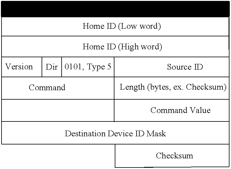
The frame format according to the first embodiment can be described as:
TABLE 1
Figure US06856236-20050215-C00001

Wherein:
    • The numbers 0 through 15 represent a bit-scale giving the order and sizes of each part of the frame. The order in which the parts appear are not restrictive and different orders can be used.
    • Home ID (32 bit): The Home ID of the system in which this frame should be executed/received.
    • Source ID (8-bit): The identifier (second part of the two-part identifier) of the transmitting controller or device.
    • Version (3 bit): Protocol/frame format version. This gives the freedom to change the frame format according to an update of the software protocol or other infrastructure enhancements.
    • Dir. (1 bit): Direction of command; 0 when a command is issued, 1 when a command is acknowledged.
    • Type (4 bit): The type of frame decides the contents of the rest of the frame, whether the frame contains a command or e.g. a status, and how the designation of devices is carried out. The designation depends on which and how many devices should be addressed. Some examples of possible frame types are:
TABLE 2
Frame Types
Type field Type function
0 (0000) Invalid use
1 (0001) Command for a single device
2 (0010) Command for a group of devices
3 (0011) Command for a group of devices, masked (Device ID 1-8)
4 (0100) Command for a group of devices, masked (Device ID 9-16)
5 (0101) Command for a group of devices, masked (Device ID 1-16)
6 (0101) Command for a group of devices in same single mask range
(*)
7 (0111) Command for a single device (repeat path)
8 (1000) Command for a group of devices (repeat path)
9 (1001) Command for a group of devices, masked (Device ID 1-8)
(repeat path)
10 (1010) Command for a group of devices, masked (Device ID 9-16)
(repeat path)
11 (1011) Command for a group of devices, masked (Device ID 1-16)
(repeat path)
12 (1100) Command for a group of devices in same single mask range
(*)(repeat path).
*) Each mask range is in step of 8 consecutive devices in step of 8. Ex. Range 0 = 1-8, Range 1: 9-16
    • Length (8 bit): Amount of bytes in the frame starting from the first Home ID word until the last data byte without checksum field.
    • Command (8 bit): The command that should be performed. See examples of commands in Table 3.
    • Command Value (8 bit): The actual value of the issued command. Typically an 8-bit value but may be longer depending on the command.
    • Data byte (0−n): The data contained in the frame.
    • Checksum (8 bit): Checksum calculated between Home ID and the last byte of the frame. The Checksum field itself is not in calculated.
In the following, some examples of information exceeding the general frame format that can be comprised in a frame are given.
The following table shows some examples of commands and command values that can be issued in a frame:
TABLE 3
Command function Command Command Value
Invalid value 0 Non applicable
Toggle switch on 1 Non applicable
Toggle switch off 2 Non applicable
Start Dim
3 Dim Level to start from
Stop Dim 4 Non applicable
All Off 5 Non applicable
All On 6 Non applicable
Delete All Switches 7 Non applicable
Request Device Info 8 Non applicable
Set Dim
9 Dim Level
Enable repeat Path 10 Non applicable
Disable Repeat path 11 Non applicable
Set Device trigger level 12 Trigger Level
Get Device trigger level 13 Non applicable
Trigger alert
14 Trigger level
Perform calibration
15 Non applicable
Request status 16 Non applicable
Supply input related data 17 data identifier
Supply output related data 18 data identifier
Supply stored data 19 data identifier
Update controller memory 20 Non applicable
Identical copy of controller 21 Non applicable
Learn Home ID 22 Home ID #
Learn Device ID 23 Device ID #
Learn Group ID 24 Group ID #, device ID #
Learn Mood ID 25 Mood ID #, Device/group ID
#, dim level
Learn Routing table 26 Device ID, row
Learn Device ID 27 Device ID #
Learn Controller ID 28 Controller ID #
At least command values of command 22, 24, 25, and 26 will be longer than 8 bit. The communication protocol designates the length of command values for each command. When issuing commands, it is off course important to specify which devices the command is addressed to. Depending on the number of devices to be addressed in one frame, different frame types, referring to Table 2, can be utilized. The following frame type comprises the command and the individual addresses, i.e. Device ID's, of a group of recipient devices.
TABLE 4
Figure US06856236-20050215-C00002
    • Destination Device ID (8 bit): Array of 8 bit destination device ID's indicating whether the receiving device should react to the command or not.
      Masking
As can be seen in the above frame format, the addressing of devices makes up a considerable amount of the total data bits to be sent. It is an important feature of the communication protocol of the first embodiment of the present invention that it provides a way to reduce the addressing data bits. By using a Destination Device ID Mask in the frame format, the addressing data bits can be reduced dramatically. The masking of Device ID's is an operation that indicates whether certain of the receiving devices should react to the command or not. A register of entries, each entry corresponding to the enumeration of Device ID's, holds a bit pattern called a mask with each bit set to ‘1’ where a corresponding Device ID is to be selected and ‘0’ otherwise. By transmitting a frame with the frame type defining the mask range, see table 2, together with the “Destination Device ID Mask” (with each bit indicating whether the receiving device should react to the command or not), the addressing of each further only takes up 1 bit.
Three examples of masking of Device ID's are given in the following. The examples use mask sizes, types, indexing and layout according to the frame format of the first preferred embodiment of the present invention. Such masking can be carried out using other layouts and formats, and the first embodiment does not restrict the idea of using masking in the designation of devices for addressing groups of devices within any communication network.
First, with an 8 bit Destination Device ID Mask, up to eight devices with Device ID's from 1-8 can be addressed in a single byte reducing the amount of data dramatically. If eight devices should be addressed with the non-masked frame format (Command for a group of devices) the amount of data would be increased with 8 bytes (8 Device ID's and the “Number of Devices” field rather than the “Destination Device ID Mask”).
TABLE 5
Figure US06856236-20050215-C00003
    • Destination Device ID Mask (8 bit): 1 bytes destination device ID mask with each bit indicating whether the receiving device should react to the command or not. The least significant bit (LSB) represents Device 1.
If we wanted to address devices in the range from 9-16 the only change in the frame format would be another value in the frame type field of the general frame format, namely 0100 from Table 2, the LSB in the mask would now be device ID 9.
If the devices to be addressed all have Device ID's within the interval 1 to 16, the frame format should be of the “masked Device ID 1-16” frame type. Thereby, some, or all, of the first 16 device ID's can be addressed in two bytes as shown in Table 6.
TABLE 6
Figure US06856236-20050215-C00004
    • Destination Device ID Mask (16 bit): 2 bytes destination device ID mask with each bit indicating whether the receiving device should react to the command or not. The least significant bit (LSB) represents Device 1.
Many systems in small households will have the most of its capacity covered by the 8 and 16 bit masks covering the first 16 devices. However, in large systems the devices to be addressed have Device ID's higher than 16, and depending of the number of devices, a more flexible masking procedure can advantageously be applied. Whereas the frame type field typically defines the devices corresponding to the mask, the frame type may also allow for a Mask Index range defining which 8 (or other number of) devices are covered by the following Destination Device ID Mask.
Each mask range covers 8 consecutive devices ID's in step of 8 (with the exception of frame type 5). In the frame type 6 frame format, a Mask Index (an 8 bit value) indicates which mask range the following Destination Device ID Mask covers. The mask ranges are numbered consecutively, hence Mask Index ‘0’ indicates a Destination Device ID Mask ranging from Device ID 1 to 8. Mask Index of 1 indicates a Destination Device ID Mask ranging from 9 to 16. Using this method Device ID ranges up to Device ID 2040 (255*8) can be addressed
TABLE 7
Figure US06856236-20050215-C00005
    • Mask Index (8 bit): The mask index indicates which Device ID ranges the Destination Device ID mask refers to.
    • Destination Device ID Mask (8 bit): 1 bytes destination device ID mask with each bit indicating whether the receiving device should react to the command or not. The least significant bit (LSB) represents Device ID=Mask Index*8+1.
A masking procedure similar to the one described above can be applied to the commands issued to different devices. Thereby, several commands from a set of predetermined commands can be issued without providing the commands as such in the frame.
By providing tables of predetermined commands such as Table 3 in the protocol on both controllers and devices, the mask will be a register of entries, each entry corresponding to the enumeration of commands, forming a bit pattern with each bit set to ‘1’ where a corresponding command is to be selected and ‘0’ otherwise. The command values of Table 3 can be subject to a similar masking.
In order to further reduce the size of frames, data such as arrays of measured input values, images or text strings such as program strings can be subject to data compression. The protocol can apply typical software digital data compression archive formats such as Zip, gzip, CAB, ARJ, ARC, and LZH.
Acknowledgement
Data transmission using a RF carrier frequency in a typical home environment creates the possibility of transmission failure and introduction of spurious errors. The sources for introduction of errors include RF noise from other RF transceivers and electrical apparatus in general. The system of the present invention uses two-way RF components making it possible to get acknowledgment back from devices after a transmitted command has been received and executed. This procedure is outlined in the flow diagram of FIG. 3. After the device has generated and sent the frame, it waits for acknowledgement from the device(s) receiving the frame. If the transmitting device has not received an acknowledgement within a specified time, it will retry the data transmission until the data has successfully been transferred or a maximum of retries has been reached.
When a frame has been received, the receiving part is prompted acknowledge the reception by the communication protocol. The destination device that received the command returns the frame with the D bit set and the receiving parts Device ID as the only Device ID in the frame. The Command Value field is used to pass the command return value (Success, Failure, etc). When the D bit is set, all devices read the frame so that the Source ID is considered Destination Device ID.
TABLE 8
Figure US06856236-20050215-C00006
The controller collects the acknowledgement replies and displays a “Command successfully executed” message if all devices have received and executed the issued command. If, after a maximum number of retries, the controller have not received acknowledgement replies from one or more devices, or if it receives return commands different from “Success”, it can display an error or warning message. The detail of such error message depends on the capacity of the system.
Depending of the capacity of the controller, the system may build a topology map of the system network. This topology map comprises a plan of the building or site where the system is installed, with the position of the individual devices marked on the plan. Thereby it becomes possible to specify information relating to individual devices such as which devices do not acknowledge an issued command or which input device detected what and where. If the controller does not have a large capacity, each device may still be named (e.g. “Hallway Dome lamp”) in order for the user to locate a device with a malfunction.
Repeating
Due to the limited range of RF signals, signal repeaters are applied in the system in order to increase the physical coverage of the system. Repeaters are known from the prior art, but the system according to the present invention includes several new features described in the following.
In the first embodiment of the present invention, all devices, whatever function they perform, are adapted to act as repeater if instructed so by a controller.
When addressing devices, it is important to take into consideration that the frame may have to be repeated by one or more times. The following frame type comprises the command, the destination identifier of the addressed device, and the repeater identifiers being the device identifiers of the devices used to repeat the signal for it to reach the destination device.
TABLE 9
Figure US06856236-20050215-C00007
    • Number of repeater (8 bit): the amount of repeater ID's in the frame.
    • Hops (8 bit): 1 byte field indicating how many repeaters the frame has passed through. This could be used by the repeaters as an index into the repeater ID's and to see whether they have to forward this frame or not.
    • Repeater ID (8 bit): 1 byte repeater ID indicting which path the frame should pass through. The Hops field can be used as an index into the repeater ID list
The repeater specific fields (Number of repeaters, Hops and repeater ID's) can be applied to all the above-mentioned frame types specified in Table 2 and will also be used in the acknowledgement of received frames.
The masking procedure described in relation to Tables 5 through 7 can also be applied when a large number of repeater identifiers are included in a frame.
Appointing Repeaters
To be able to transmit signals using repeaters an automated process is performed to appoint devices as repeaters. It is important that the amount of repeaters in a given system is kept to a minimum in order for the response time to be as low as possible. It is desirable not to do the automated repeater location process to often as it takes time and consumes power and thereby battery life.
FIG. 4 to FIG. 12 illustrates the steps of the automated repeater detection process used to appoint devices as repeaters according to the first preferred embodiment. FIG. 4 shows a topology map for the whole system. Devices within signal range of each other are connected by lines. The ellipse shows the range of the controller.
In FIG. 5 the controller asks all devices within the range of the controller, device 20, 21 22 23 and 24, of how many other devices are within their range. Device 20, 21 22 and 24 can reach three other devices and device 23 can reach four.
FIG. 6 shows that the device that could reach most new devices, here device 23, is now appointed Repeater. Now, each single device within the range of the controller is asked how many devices cannot reach any new devices. Device 20, 21 and 22 in the upper left corner cannot reach any, but device 24 can reach two new.
FIG. 7 shows that two devices, namely 23 and 24, have been appointed Repeaters while three devices, namely 20, 21 and 22, have been declared unsuitable as Repeaters. The newly appointed Repeater 24 can reach two new devices 25 and 26. Device 25 can reach three new devices whereas device 26 can reach one new device.
FIG. 8 shows that the device 25, which could reach three new devices, has now been appointed Repeater. Two of those three devices, namely 27 and 30, can each reach three new devices and one, namely 32, can reach one new device.
FIG. 9 shows that of the two devices 27 and 30, which could reach the same 3 new devices, one (27) is randomly appointed Repeater. It can be seen that the four devices, 28, 29, 30 and 31, cannot reach any new devices while the two devices 26 and 32 each can reach one new device.
FIG. 10 shows that device 26 is randomly appointed Repeater. There are now two potential repeaters, one (device 32) which cannot reach any new devices and one (device 33) which can reach two new devices.
FIG. 11 shows the device 33, which can reach the last two devices 34 and 35, is appointed Repeater.
The final configured system with the necessary 6 repeaters is presented in FIG. 12. We have achieved that it is possible to reach any switch from any repeater. It is important to understand that even though a device has been appointed, it still function as a normal input/output device when receiving a signal having its identifier as destination identifier.
Having appointed repeaters in the system for the current position of the controller, all devices can be addressed using the process outlined in 13 to FIG. 18. The topology of the system is shown in FIG. 13, where circles indicates devices acting as repeater number Rn and the triangles are devices with numbers as indicated. After having performed this process, the controller will know which repeaters to use in order to reach any device in the system.
FIG. 14 shows that at first, the controller finds out which of the devices and Repeaters it can address directly by sending a multi-address telegram containing a list of all devices and Repeaters in the system. Time slices are allocated so that all devices have time to acknowledge the command to the controller. Which time slice each single device can apply depends on the location of the device on the list.
FIG. 15 shows that the controller have received acknowledgement replies and thereby knows that it can communicate with devices 1-7 and Repeater 1 (R1). It then asks R1 to forward a multi-address telegram containing a list of the missing devices (8-10) and their command. It also sends a list of all non-used Repeaters (R2-R4). It reaches devices (8) and Repeaters (R2 R3).
FIG. 16 shows that the controller now knows that it can communicate with Repeater (R2) via Repeater (R1). It then asks R2 to send a multi-address telegram containing a list of the missing devices (9-10) and their command. It also sends a list of all non-used Repeaters (R2-R4). It finds devices (9) and Repeaters (R4).
FIG. 17 shows Repeater (R1) asks R3 to forward a multi-address telegram containing the missing device (10) and its command. R3 replies, through R1, that it can not see device 10.
FIG. 18 shows the controller knows that it can communicate with Repeater (R4) via Repeater (R1 and R2). It then asks R4 to forward a multi-address telegram containing the missing device (10) and its command. R4 replies, through R2 and R1, that it can reach device 10.
Now, the controller will know which repeaters to use in order to reach any device in the system, and can generate a frame of frame type 7 as shown in Table 9, comprising the correct repeater identifiers for the repeaters to reach a given destination device.
Routing Table
As an alternative to the above approach used to appoint and address devices as repeaters, the automated repeater detection process described in relation to FIG. 4 to FIG. 12 can be used to build a routing table or a topology table from which a route of repeaters to reach a given device can be extracted. In the table, a “1” designates, that the device of the column can be used to repeat a signal addressed to the device of the row. A “0” designates that the corresponding devices can not reach each other directly. In the topology of the system shown in FIG. 4 to FIG. 12, the routing table is:
TABLE 10
20 21 22 23 24 25 26 27 28 29 30 31 32 33 34 35
20 0 1 1 1 0 0 0 0 0 0 0 0 0 0 0 0
21 1 0 1 1 0 0 0 0 0 0 0 0 0 0 0 0
22 1 1 0 1 0 0 0 0 0 0 0 0 0 0 0 0
23 1 1 1 0 1 0 0 0 0 0 0 0 0 0 0 0
24 0 0 0 1 0 1 1 0 0 0 0 0 0 0 0 0
25 0 0 0 0 1 0 1 1 0 0 1 0 1 0 0 0
26 0 0 0 0 1 1 0 0 0 0 0 0 0 1 0 0
27 0 0 0 0 0 1 0 0 1 0 1 1 0 0 0 0
28 0 0 0 0 0 0 0 1 0 1 1 1 0 0 0 0
29 0 0 0 0 0 0 0 0 1 0 0 1 0 0 0 0
30 0 0 0 0 0 1 0 1 1 0 0 1 0 0 0 0
31 0 0 0 0 0 0 0 1 1 1 1 0 0 0 0 0
32 0 0 0 0 0 1 0 0 0 0 0 0 0 1 0 0
33 0 0 0 0 0 0 1 0 0 0 0 0 1 0 1 1
34 0 0 0 0 0 0 0 0 0 0 0 0 0 1 0 1
35 0 0 0 0 0 0 0 0 0 0 0 0 0 1 1 0
In this alternative approach, the following method is used to determine which devices to assign as repeaters in a frame of frame type 7 as shown in Table 9.
  • 1. Send signal directly to destination device and wait for acknowledge.
  • 2. If no acknowledge is received, find the first device having a “1” in the row of the destination device in the routing table, include the identifier of this device as a repeater identifier in the signal and transmit signal again.
  • 3. If no acknowledge is received, repeat step 2 for the next devices having a “1” in the row of the destination device in the routing table.
  • 4. If no acknowledge is received, find the first device having a “1” in the row of the repeater device of step 2 in the routing table, include the identifier of this device and the repeater device of step 2 as a repeater identifiers in the signal and transmit signal again.
  • 5. If no acknowledge is received, repeat step 5 for the next devices having a “1” in the row of the repeater device of step 2 in the routing table.
  • 6. If no acknowledge is received, repeat step 5 for the first repeater device from step 3.
  • 7. etc.
The user interface administers setup of the system by the user, and hence allows for the user to perform functions such as learning of new devices, setup of groups and moods, updating shared information between controllers etc, some of which will be described in the following these functions are performed by programs or routines stored in the processor of the controller.
Controller Replication/Update
Since a device shall respond to all controllers in a household, all controllers are programmed with the Home ID (i.e. the unique identifier of the first controller utilized to program a device). Also, some functions, groups, moods or other tables in the system may be “universal” in the sense that it is preferable to have the same tables on all controllers in the system, even though they are originally learned on one specific controller. This is possible in the system of the present invention, since controllers, whether new or already in use, can learn from another in order to share information such as in copying of information from one controller to another or updating changes performed in the shared information of one controller.
This is done by putting the first controller in “Teach Mode” and the second controllers in “Learning mode” and starting the transfer on the transmitting first controller. It is possible to make the memory of the learning controller a complete copy/replication of the corresponding memory of the teaching controller. Also, the learning controller can be updated with data from the first controller, typically only the home ID, the device table, and the routing table, in order to learn the controller of the new devices introduced in the system.
The transfer of data is performed in a sequence of signals having frame type 1 (see Table 2) since it addresses only a single device, the learning controller. The command type (see Table 3) of the first signal determines which type of learning, complete copy (command 21) or updating (command 20), is to take place. In the following signals, the Home ID, device ID table, group table etc is transferred using the command types 22-26 of Table 3. A typical frame, transfer of device ID table comprising three devices, is:
TABLE 11
Figure US06856236-20050215-C00008
It is possible to mask the command values in case of transfer of larger tables such as the routing table.
Learning of New Devices
The system is very flexible and additional devices can easily be added as time goes by. When a new device is added to the system it has to know which Home ID and individual Device ID to use. This procedure requires only three actions by the user, using only the device to be installed and any one controller. Everything else is taken care of by the system, and does not involve or affect any other controller or device in the system. In the first preferred embodiment, the system learns the presence of the new device and assigns a Device ID in an automated process following the process steps:
  • 1. The user sets the controller in a learning programming state where it listens to all signals, not only to those with the correct home ID.
  • 2. The user presses and holds a button on the device.
  • 3. The device sends request for Home ID and Device ID to listening controller as mentioned in 1.
  • 4. Device awaits frame with Home ID and Device ID from controller.
  • 5. Controller looks up next available Device ID and sends Home ID and allocated Device ID to device.
  • 6. Device stores the received Home ID and Device ID in non-volatile memory.
  • 7. The new device is added in the device table, and may be added in the group table and may be named.
The signal for assigning the device (or controller) ID to a new device (or controller) has frame type 1 (see Table 2) since it addresses only a single device. The commands used are command 27 (assigning device ID) and command 28 (assigning controller ID), a typical frame, assigning device ID is:
TABLE 12
Figure US06856236-20050215-C00009
In the alternative where the device is programmed with a unique Device ID from factory, the process will be somewhat simpler:
  • 1. The user sets the controller in device programming state, and is requested to specify which group the new device should be placed in.
  • 2. The user presses and holds a button on the device whereby the device sends its Device ID to listening controller as mentioned in 1.
  • 3. Device awaits frame with Home ID from controller.
  • 4. Controller sends Home ID to device.
  • 5. Device stores the received Home ID in non-volatile memory.
  • 6. The group table in non-volatile memory on the controller is updated with the new Device ID.
The simplicity of this procedure is due to the unique addresses of all devices in the system. Since all devices can be addressed individually and due to the functionality of the protocol, each device can be set up and included/excluded individually.
If the device is already within the device table of the controller, but have to be added to a new or existing group, the procedure comprises the following steps:
  • 1. The user sets the controller in group programming state and the user is requested to specify which group the new device should be placed in.
  • 2. The user presses and holds a button on the device.
  • 3. The device sends its Device ID to listening controller.
  • 4. Controller stores the received Device ID in the selected group table.
If the controller has large capacity and is capable of building and administering topology maps, the procedure may be carried out differently, e.g. by simply installing the device physically and thereafter positioning a new device on the corresponding position in the topology map on the controller. The system may now itself find which (existing or new) repeaters should be used to communicate with the new device and may itself prepare the device for receiving Home and Device ID.
The learning processes outlined above may be organized differently, however it is important for the overall functionality of the system that the device and the controller themselves (assign and) learn each other's ID's. Devices can belong to several groups, and a single device is inserted in a group by adding its Device ID to the relevant group table in the controller memory, hence without influence for any other devices at any time.
Data Structure in Controller
In order to keep the signals as short and few, the system according to the first preferred embodiment is optimized to operate as simple as possible without loosing quality in terms of reliability, range/coverage, versatility, and flexibility. In the following, the data structure of the controller, which allows for sharing information and performing functions in the most appropriate and efficient manner, is described.
Device Table
This table holds information on all the devices, which are currently installed in the complete system. This table is also used to assign device identifiers to new devices in the system. This table may also contain information about the characteristics or fixed settings of the different devices. This table can also holds information related to the childproof function such as the code.
Group Table
This table holds information on which devices from the Device Table that are grouped together in which group. This table also holds information on the current setting of the specific group.
Mood Table
The Mood Table holds information on which groups and devices are members of the specific Mood and it also holds the specific settings of each device in the mood.
Group and Mood Name Tables
These two tables contain the user-defined alphanumerical names for the different groups and moods.
Controller Table
This table holds information on all controllers presently in the system, and optionally also the date and time of the last learning from another controller. This table could also contain information about the characteristics of the different controllers.
Repeater Table
This table holds information on (the identifiers of) all devices which act as repeaters, and information of which devices can be reached by each repeater.
Topology Map Table
This table holds information of all the known devices in the system and their location in system. This table also contains information of the individual devices such as alphanumerical names, characteristics and their current settings.
In the alternative approach described earlier, a routing table, such as Table 10 can replace the repeater table and the Topology map.
Trigger Action Table
This table holds information about which actions to take when a trigger level on one or more of the input devices has been reached.
Event Table
This table is similar to the Trigger Action Table. It holds certain events in the form of small programs, which is executed when predetermined conditions are fulfilled. Examples are turning on the coffee machine or car heater when a certain time has been read from the timer.
Program Table
This table holds large programs, macros or routines to be executed on command.
The system according to the first preferred embodiment can be used in a broad variety of locations to control a broad variety of functions. The system can be installed in private homes, hotels, conference centers, industrial offices, storehouses, various institutions such as kinder gardens, schools, old people's home, disabled person's home etc. In the following, examples of build-in functions in the system of the first preferred embodiment are described.
Child Protection Function
One of the functions is the Child Protection Function. This allows the user to restrict the use of one or more devices by use of a code or an action. The restriction can have several effects, i.e.:
    • The device or the appliance connected thereto are turned off and can not be turned on until a valid code has been entered or a predetermined action has been performed. In the first preferred embodiment, pressing an actuator on the respective device three times annuls the protection. E.g. utilized to protect children towards household appliances such as ovens, toasters, and hotplates.
    • The device or the appliance connected thereto can only operate at a specified level, for a specified period of time, or within a specified time period unless a valid code has been specified. E.g. used to restrict the output level of the Audio equipment, restrict the amount of children's TV watching when the parents are out, or restrict the solarium working periods to those actually paid for by the customer.
    • The status or operation level of the device or the appliance connected thereto can not be altered until a valid code has been specified. E.g. utilized to fix the hot water temperature at a constant temperature or fix the thermostat for the air-conditioning.
      Timer
Each controller can comprise a clock giving the date and time. This clock is used for timer functions such as for performing preprogrammed events and a time value can be read by different parts of programs comprised in the controller.
Power and Lighting
In a second preferred embodiment, also referred to as Power & Lighting control, the system comprises a set of products for controlling the power level to electric appliances connected to the devices, such as lamps, air conditioning, and kitchen appliances.
Apart from being a Power & Lighting control system, the system of the second preferred embodiment is to form a base for a complete home control system including other subsystems such as HVAC control, alarm system control, access control, etc.
The automation system of the second preferred embodiment is built on the same platform as the automation system of the first preferred embodiment. Thus, the description of the second preferred embodiment is a more detailed description of several of the functions described in relation to the first preferred embodiment, and it is assumed that the features described in relation to the first embodiment are also valid in the second embodiment.
FIG. 24 shows an implementation of a system according to the preferred embodiment. FIG. 24 shows a ground plan of a house 18 with several rooms. The house has an inlaid electricity grid consisting of conducting wires 40 (thick lines) leading to a number of electricity outlets 19 (gray squares). This compares to the electricity net for a typical building. A number of different electric appliances connected to electricity outlets are positioned around the house, these are lamps 11, TV set 12, shaver 13, toaster 14, and thermostat 15 for radiator. Each appliance is connected to a device 41, which can be remotely controlled by a controller 17 through RF signals 16.
The devices 41 can be connected between the appliance and the electricity outlet 19 such as in the case of the toaster 14, or be an integrated part of the appliances as in the case of the TV set 12. Thereby controlling the device connected thereto can control the power supply to and/or the function of an appliance. Examples of this controlling is turning the lamps 11 on/off, change the operation status such as the channel of the TV set, setting another temperature on the thermostat 15 or activating the burglar alarm 39. Also, a device can report to the controller with a status of an appliance, such as the temperature in the room of the thermostat 15 or the status of the alarm 39.
In the embodiment described in relation to FIG. 24, a mood can comprise all devices connected to lamps 11 in the living room and the settings could be the amount of power supplied to the lamp by each device. By selecting this mood, all lamps in the living room would be dimmed to a predetermined level creating desired lighting. In another example, the mood comprises all thermostats 15 in the house and the settings are the desired room temperatures in each room. Hence by selecting the mood, a predetermined temperature set-up can be set around the house.
The following description of the Power & Lighting control system mainly deals with those aspects not comprised in the high-level description of general parts of the conceptual, scaleable system given in the description of the first preferred embodiment of the automation system. However, details and features described only in relation to the second embodiment are also valid with respect to the first preferred embodiment.
The Power & Lighting control system consists of the following elements.
Controllers
In the Power & Lighting embodiment, the controller is a mobile control panel such as a remote control, so that the use or programming of the system is not restricted to certain locations. Controllers have a display such as an LCD (Liquid Crystal Display) display. The controllers can optionally interface with a computer; moreover, a computer may also act as a controller in the system. The initial implementation and often also later setting of a device is carried out in the vicinity of the device. Although the data protocols makes use of addressing of devices using device identifier's, the person performing the programming can rely on his/her visual confirmation of the connection of an appliance to a given device. Hence the programming interface does not rely on the users ability to remember device codes, assigned numbers or alike.
FIG. 19 outlines a controller according to the second preferred embodiment. The controller has the following buttons:
    • The all On/Off button which will either switch all output devices On or Off except for those device that have been configured not to be included. The set-up of this function is specified later.
    • The eight speed buttons for quick access to the most commonly used groups or moods.
    • The Group button which sets the state of the speed buttons to be groups
    • The Mood button which sets the state of the speed buttons to be moods
    • The OK button which is mainly used within the menu system.
    • The Left and Right buttons which among other things are used to maneuver in the menu system.
Among other things, the following actions can be performed with the controller:
    • Programming devices to belong to the system (i.e. programming them with the unique Home ID number)
    • Assigning identifiers to new devices.
    • Programming devices to belong to one or several groups
    • Executing the on/off function on a given group
    • Executing the dim function on a given group
    • Programming devices to belong to one or several moods
    • Executing a given mood
    • Naming a given group with alphanumerical characters
    • Naming a given mood with alphanumerical characters
    • Setting a child protection on a device
    • Programming the timer
    • Initiating and interrupting the keylock function
    • Etc.
Several controllers can be utilized within a system, and signals from a first to a second controller can be related to:
    • Learning of Home ID and assigning of controller ID.
    • Replication or updating of various data on controllers.
      Output Devices
The output devices are operationally connected between a power source and an electric appliance, typically in the form of an outlet socket connected to the power supply socket. The output devices can perform switching, dimming and optionally metering of power or current delivered to the electric appliance. Also, the output devices are able to perform as repeaters in the system.
A number of different types of output devices are feasible, ranging from low voltage switches to HVAC output devices etc. Each output device has only one actuator button. This button is used every time the device should notify a controller of its Device ID during programming procedures. The button can also be used to turn on/off and dim the output power supplied by the device without the use of a controller. However, this function can be overruled by the child protection function by making the button inactive for power adjustment purposes. The different functions of the button are utilized by pressing the button for different periods of time, e.g. a short period for turning on/off and dimming up/down when the button is pressed continuously.
Among other things, the output devices can perform the following actions:
    • Inform a controller of its presence and get ready to receive the Home ID and Device ID.
    • Toggle the current on/off by use of a button on the device
    • Dim the current by use of a button on the device
    • Execute commands received from a controller
      • Dim the current
      • Repeat the command received to other output devices
      • Toggle the current On/Off
      • Acknowledgement of received and executed commands
      • Reply with device status
    • Meter the power or current supplied to the electric appliance connected to the output device, and save, process and transmit the metered information.
The following paragraphs describe some of the functionality comprised in the Lighting system.
Group or Mood Switching
By pressing “Group Button” the user enters functions dealing with a single or a group of appliances such as lamps. By pressing “Mood Button” the user enters functions dealing with moods (e.g. setting a predefined Lighting for the room).
Group On/Off Setting
A user can turn on or off a single or a group of appliances by either using the speed buttons 1-8 or by using the scroll button. If the user uses button 1-8 then only a short press is required. The button will work as a toggle. If the scroll button is used the user must scroll to the desired group and press an OK button.
Group Dim Setting
A user can dim the current to a single or a group of appliances such as lamps (the same group as the on/off function) by either using the speed buttons 1-8 or by using the scroll button. If buttons 1-8 is used, the dimming will be activated when the button is pressed continuously. When the correct dimming level is reached the button is released. If the scroll button is used the user must scroll to the desired group and press additional buttons to dim up/down.
Command Acknowledgement on Display
Each command initiated by the user will be acknowledged through the display. A typical acknowledgement could for example be that “all lights are now off.” Upon activating a device, the control panel expects an acknowledgement receipt from the device that the command has been carried out. Two events can occur:
    • The device does not respond with an acknowledgement:
      • The controller indicates e.g. “out of reach or device defect”
    • The device responds with an error message such as No Current Detected In Mains:
      • The controller indicates e.g. “Bulb or lamp defect”
    • The device responds with Command Executed:
      • The controller indicates e.g. “All OK”
        Mood Programming Function
Moods can be programmed into the control panel by pre-setting the different devices to the desired current level, and afterwards storing this level in the control panel. Moods can be stored in buttons 1-8 or by using the scroll button for additional storage.
Mood Setting Function
A user can activate pre-set moods (e.g. TV watching or working mood) by using the control panel's 1-8 buttons. If the scroll button is used the user must scroll to the desired group and press an OK button.
All On/Off Setting
A user can turn on or off all switches by pressing the “all on/off” button. A device will per default be programmed to respond to the “all on/off” button, but can also be programmed not to.
All On/Off Programming
Should a user require that a certain device should not respond to “all on/off” it can be done so by setting this on the control panel. This could e.g. be beneficial for the fish tank or the outdoor lights.
Random On/Off Setting
The user can use the control panel to set a device to random turn on and off (i.e. used to keep away burglars). The device will keep turning on and off with e.g. 3 hrs. interval and abort this action next time it receives any instruction from the control panel. The time interval in which the control panel should randomly switch on and off can also be set (e.g. from 18:00 to 23:00)
Random On/Off Programming
Should a user require that a certain device should not respond to “random on/off” it can be done so by setting this on the control panel. This could e.g. be beneficial for the fish tank or the outdoor lights.
Device Resetting
All devices can be reset whereby the Home ID and the Device ID held by the device is deleted and all references to the Device ID in the controller is deleted. In the Power & Lighting embodiment, the resetting is carried out by setting the controller in “device reset” mode and pressing the actuator button on the device. This makes the device transmit information to the controller, which then perform the resetting.
Programming and Learning
In the following, the procedures for performing some of the programming and learning functions within the systems are outlined with reference to FIGS. 20 to 22. In the user interface the choices are presented as menus on the LCD display of the controller, and can be selected using buttons under the display.
Group Menu
When selecting the group menu on the main menu, the following three things can be done to the groups after they have been created such as during addition of new devices.
    • Name the group: Each group can be named with alphanumerical numbers to improve the user friendliness.
    • Remove a switch from a group: When the different devices have been added to a specific group then this menu functionality enables the user to remove individual switches from a specific group. The procedure of how this is done is shown in FIG. 20. First the user selects the “Remove Switch from Group” menu option and is prompted for the group number in which the device is to be removed. Then the user has to press a button on the output device in order for controller to get the device id to remove. When the button on the output device has been pressed to specific device has been removed from the group table and the menu system return to the main menu.
    • Delete a group: This menu item allows the user to completely delete a group.
      Mood Menu
Moods are groups of devices in which the setting of each device is set to a desired dim level or current. When selecting the mood menu on the main menu, the following options are available in the mood menu section.
    • Create a Mood: This menu item allows the user to add devices into a mood. The procedure is outlined in FIG. 21. First the user selects the “create a Mood” menu option and is prompted to select devices to include in the mood. The user then presses a button on all of the output devices which are to be included in the mood and presses OK when done. The output devices then transmit its current dim level to the controller. Then the user is prompted for a mood number to add the already selected devices into. If the mood is already is in use then user has to determine whether to replace the mood with the selected devices or to choose another mood number. The user then has the option to name the mood. The user can now select the alphanumerical characters on a toggle menu using the Left/Right and the OK button. When the name is typed, the user holds the OK button for more than 2 seconds whereby the controller saves the mood name and returns to the main menu.
    • Name a Mood: Each mood can be named with alphanumerical numbers to improve the user friendliness.
    • Removed switches from Mood: When the different devices have been added to a specific mood then this menu functionality enables the user to remove individual switches from a specific mood again. The method is equivalent to the method used when removing switches from groups.
    • Delete a Mood: The menu item allows the user to completely delete a mood.
The all On/Off functionality is per default set to be all devices known by the controller. Individual switches can repeatable be removed or added from this function. There is also a possibility to customize whether the button is to toggle On/Off or only to use this button as a switch off button.
Controller Replication
To ease the use of having several controllers operating within the same Home ID the product has the feature to update each other with the different tables and settings. The updating process is shown in FIG. 22. The user is first prompted for whether the current controller should send data to the other controller or receive data from the other controller. If the user selects receiving data the controller enters a learning-programming mode and will return to the main menu when the updates has been received. If the user selects the option to send data, the user is prompted for whether he/she wants to update the other controller or make an identical copy/replication of current controller. If the update is chosen, only specific data is transmitted. If identical copy/replication is chosen, the Home ID and all tables containing Groups, Moods, etc. is transmitted. When the update or identical copy/replication is completed, the system returns to the main menu.
Hardware
Power Meter
Some or all the output devices can include means for measuring the power supplied to the one or more appliances connected to each device. The power measuring means are means for measuring the current supplied to the appliance at constant voltage, in order to allow for determination of the power, in e.g. KW/h or VoltAmpere/h, received by the one or more appliances connected to the device. A possible way to implement power meter functionality in the existing switches is outlined in FIG. 23. This implementation requires the consuming appliance to pull it's current in a sinus form which would be the case for ordinary lamps. The power meter would then be able to measure volt-amperes, which would be identical to Watts.
This power meter function allows the controller to monitor the power consumption of individual appliances, all appliances in a given group, all appliances in a given mood, and of all appliances connected to the system. Hence, one can practice a total power metering, revealing detailed information of specific appliances or sections in the building. The devices are adapted to sum up the power consumption for a given period of time and to report the power consumption to a controller either in response to a request to do so from the controller, or on its own motion at e.g. a predetermined time or total power consumption.
The controllers and the devices according to the first and/or second embodiment have some common hardware such as:
    • RF Transceiver with the following characteristics:
      • Very flexible frequency band
      • Programmable output power
      • Data-rate up to 9600 bit/s
      • FSK modulation
      • Suitable for frequency hopping protocols
      • Low power consumption
    • Microprocessor with the following characteristics:
      • High Speed RISC Architecture
      • Very Low power consumption
      • Integrated RAM, EEPROM and FLASH memory
In the second embodiment, the Power & Lighting system, the control panel and the output devices further comprises:
The control panel:
    • Two line LCD display
    • 13 button soft keypad
    • Battery holder for three type AAA batteries
    • Timer chip which is used to show the time and set timers for the burglar deterrent function.
The output devices:
    • The components on the devices are powered from the 220/110-volt power outlets in the wall after it has been transformed down to 3.3v. The dim and on/off function is controlled by a very powerful TRIAC. The output devices have one actuator button used in programming procedures and to adjust the power supplied by the device.

Claims (21)

1. An automation system for controlling and monitoring devices comprising:
a plurality of devices to be controlled, each device comprising:
a radio frequency receiver for receiving signals,
a radio frequency transmitter for transmitting signals,
a processor for administering the reception and transmission of signals,
a first memory adapted to hold a device identifier identifying the device, and
means for providing an output to, or receiving an input from, an appliance operationally connected to the device,
a first controller comprising:
a radio frequency transmitter for transmitting signals,
a radio frequency receiver for receiving signals,
a first memory comprising an organized data structure holding device identifiers of devices controlled by the first controller,
a second memory holding a controller identifier identifying the first controller, and
a processor for administering the reception and transmission of signals and being adapted to store one or more device identifiers in the first memory, the processor comprising means for generating a first signal comprising one or more destination identifiers corresponding to device identifiers of one or more destination devices, information related to the operation of the appliances connected to said destination devices, and, if necessary, repeater identifiers corresponding to one or more signal repeating devices,
wherein one or more of the plurality of devices are adapted to
act as signal repeating devices in that the processors of each of said one or more devices comprises means for, upon reception or a first signal, processing said information in its processor if one of the one or more destination identifiers corresponds to the device identifier of the device, and means for, upon reception of a first signal, transmitting a second signal holding at least said destination identifiers and said information if one of the one or more repeater identifiers corresponds to the device identifier of the device, and
act as I/O devices in that the processors of each of said one or more devices comprises means for generating an event signal in response to input received from an appliance or user, the event signal comprising one or more destination identifiers corresponding to controller or device identifiers of one or more destination controllers or destination devices.
2. An automation system according to claim 1, wherein all devices are adapted to act as repeating devices.
3. An automation system according to claim 1, wherein the first memory of the first controller comprises a routing table indicating, for each device, other devices which can receive and process a signal transmitted by said device.
4. An automation system according to claim 3, wherein the processor of the first controller comprises means for identifying in the routing table device identifiers of devices for repeating a first signal having a predetermined destination identifier, and to include said device identifiers as repeater identifiers in the first signal.
5. An automation system according to claim 1, wherein one or more of the plurality of devices are further adapted to receive an input from the appliance connected thereto, and wherein the processor of a device is adapted to, in response to the received input, generate and transmit a first signal.
6. An automation system according to claim 5, wherein the received input or data corresponding thereto is comprised in the first signal.
7. An automation system according to claim 5, wherein the received input is stored in the first memory of the device.
8. An automation system according to claim 1, wherein the appliance connected to one or more of the plurality of devices is a sensor selected from the group consisting of electromagnetic radiation sensor, luminosity sensor, moisture sensor, movement sensor, temperature sensor, mechanical actuator contact, sound sensor, pressure sensor, electric signal sensor, smoke detector, audio pattern recognizing means, visual pattern recognizing means and molecular composition analyzing means.
9. An automation system according to claim 8, wherein the sensor measures the impedance, capacitance, resistance, or inductance of an electric signal.
10. An automation system according to claim 1, wherein one or more of the plurality of devices are further adapted to generate an output to the appliance connected thereto in response to a received signal, said output being related to the operational state of the appliance.
11. An automation system according to claim 10, wherein the output is electric power, and wherein a device can adjust the output power at a level according to a setting comprised in the received signal.
12. An automation system according to claim 10, wherein a device is adapted to prohibit the output in response to a received first set of instructions or a first code or predetermined action provided by the user, and wherein said restriction can only be removed in response to a received second set of instructions or a second code or predetermined action provided by the user.
13. An automation system according to claim 12, wherein the first controller is adapted to generate the first and the second set of instructions, and wherein the user is must provide a code or perform a predetermined action in order for the first controller to generate said second set of instructions.
14. A method for establishing an RF automation system network for controlling and monitoring devices, said method comprising the steps of:
providing a first controller comprising:
a radio frequency transmitter for transmitting signals,
a radio frequency receiver for receiving signals,
a first memory comprising an organized data structure holding device identifiers of devices controlled by the first controller,
a second memory holding a controller identifier identifying the first controller, and
a processor for administering the reception and transmission of signals and being adapted to store one or more device identifiers in the first memory,
providing a plurality of devices to be controlled by the first controller, each device comprising:
a radio frequency receiver for receiving signals,
a radio frequency transmitter for transmitting signals,
a processor for administering the reception and transmission of signals,
a first memory adapted to hold a device identifier identifying the device, and
a processor for administering the reception and transmission of signals and being adapted to provide an output to, or receive an input from, an appliance operationally connected to the device,
wherein one or more of the devices are adapted to act as I/O devices in that the processors of each of said one or more devices comprises means for generating an event signal in response to input received from an appliance or user, the event signal comprising one or more destination identifiers corresponding to controller or device identifiers of one or more destination controllers or destination devices,
generating a first signal comprising one or more destination identifiers corresponding to identifiers of one or more destination devices or destination controllers, information related to the operation of an appliance connected to a device, and one or more repeater identifiers corresponding to one or more signal repeating devices,
transmitting said first signal,
receiving the first signal at one of said plurality of devices,
if one of the one or more destination identifiers corresponds to the device identifier of the receiving device, then processing said information in the processor of the device, and
if one of the one or more repeater identifiers correspond to the device identifier of the receiving device, then transmitting a second signal holding at least said one or more destination identifiers and said information.
15. A method according to claim 14, wherein the first signal is transmitted by the first controller, the one or more destination identifiers comprised in the first signal is a device identifier, and the information comprised in the first signal comprises instructions to a processor of the destination device to provide an output to, or receive an input from, the appliance connected to the destination device.
16. A method according to claim 15, further comprising the step of receiving input from an appliance or user at the one or more I/O devices and generating an event signal in response to the received input.
17. A method according to claim 14, wherein the first signal is transmitted by a device and wherein the destination identifier comprised in the first signal is a controller identifier and wherein the information held by the first signal is related to a state or a reading of the device transmitting the first signal.
18. A method according to claim 14, further comprising the step of building a routing table indicating, for each device, other devices which can receive and process a signal transmitted by said device, and storing the routing table in the first memory of the first controller.
19. A method according to claim 18, further comprising the steps of identifying device identifiers in the routing table of devices for repeating a first signal having a predetermined destination identifier, and including said device identifiers as repeater identifiers in the first signal.
20. A method according to claim 14, further comprising tho step of, upon receiving a first or a second signal at a device, generate and transmit an acknowledgement signal having the identifier of the device or controller transmitting the first or second signal as destination identifier.
21. A method according to claim 20, wherein the acknowledgement signal comprises a destination identifier and one or more repeater identifiers, the method further comprising the steps of receiving said acknowledgement signal at a device and if one of the one or more repeater identifiers correspond to the device identifier of the receiving device, then transmitting a signal holding said destination identifiers and the acknowledgement.
US09/841,050 2000-04-10 2001-04-25 RF home automation system comprising nodes with dual functionality Expired - Lifetime US6856236B2 (en)

Priority Applications (1)

Application Number Priority Date Filing Date Title
US09/841,050 US6856236B2 (en) 2000-04-10 2001-04-25 RF home automation system comprising nodes with dual functionality

Applications Claiming Priority (2)

Application Number Priority Date Filing Date Title
US54705500A 2000-04-10 2000-04-10
US09/841,050 US6856236B2 (en) 2000-04-10 2001-04-25 RF home automation system comprising nodes with dual functionality

Related Parent Applications (1)

Application Number Title Priority Date Filing Date
US54705500A Continuation-In-Part 2000-04-10 2000-04-10

Publications (2)

Publication Number Publication Date
US20020044042A1 US20020044042A1 (en) 2002-04-18
US6856236B2 true US6856236B2 (en) 2005-02-15

Family

ID=24183157

Family Applications (2)

Application Number Title Priority Date Filing Date
US09/840,827 Expired - Fee Related US6980080B2 (en) 2000-04-10 2001-04-25 RF home automation system with replicable controllers
US09/841,050 Expired - Lifetime US6856236B2 (en) 2000-04-10 2001-04-25 RF home automation system comprising nodes with dual functionality

Family Applications Before (1)

Application Number Title Priority Date Filing Date
US09/840,827 Expired - Fee Related US6980080B2 (en) 2000-04-10 2001-04-25 RF home automation system with replicable controllers

Country Status (12)

Country Link
US (2) US6980080B2 (en)
EP (2) EP1290506B8 (en)
JP (1) JP2003530741A (en)
AT (2) ATE255733T1 (en)
AU (2) AU759777B2 (en)
CA (2) CA2391405C (en)
DE (2) DE60117133T2 (en)
DK (2) DK1275037T3 (en)
ES (2) ES2211794T3 (en)
HK (2) HK1052753B (en)
NO (1) NO321648B1 (en)
WO (2) WO2001078307A2 (en)

Cited By (141)

* Cited by examiner, † Cited by third party
Publication number Priority date Publication date Assignee Title
US20020002633A1 (en) * 2000-06-23 2002-01-03 Colling John K. Event notification system
US20030037033A1 (en) * 2001-08-20 2003-02-20 Kai Nyman Naming distribution method for ad hoc networks
US20040098172A1 (en) * 2002-11-15 2004-05-20 Abb Research Ltd. Configuration system for network appliances, and a method for reconfiguration of appliances
US20040203365A1 (en) * 2002-06-13 2004-10-14 Tetsuya Yamamoto Radio communication with an intended device
US20060049976A1 (en) * 2004-09-09 2006-03-09 Mcfarland Norman R Distance measurement for wireless building automation devices
US20060063523A1 (en) * 2004-09-21 2006-03-23 Mcfarland Norman R Portable wireless sensor for building control
US20060074494A1 (en) * 2004-09-29 2006-04-06 Mcfarland Norman R Automated position detection for wireless building automation devices
US20060071780A1 (en) * 2004-09-29 2006-04-06 Mcfarland Norman R Triangulation of position for automated building control components
US20060158037A1 (en) * 2005-01-18 2006-07-20 Danley Douglas R Fully integrated power storage and supply appliance with power uploading capability
US20070156857A1 (en) * 2005-12-29 2007-07-05 King David L Systems and methods for automatic configuration of devices within a network utilizing inherited configuration data
US20070203860A1 (en) * 2006-02-24 2007-08-30 Gridpoint, Inc. Energy budget manager
US20070271006A1 (en) * 2006-05-18 2007-11-22 Gridpoint, Inc. Modular energy control system
US20080056722A1 (en) * 2006-08-29 2008-03-06 Hendrix John A Binding methods and devices in a building automation system
US20080055073A1 (en) * 2006-09-06 2008-03-06 Lutron Electronics Co., Inc. Method of discovering a remotely-located wireless control device
US20080068126A1 (en) * 2006-09-06 2008-03-20 Lutron Electronics Co., Inc. Procedure for addressing remotely-located radio frequency components of a control system
US20080068204A1 (en) * 2006-09-06 2008-03-20 Lutron Electronics Co., Inc. Method of restoring a remote wireless control device to a known state
US20080089266A1 (en) * 2004-10-26 2008-04-17 Jean-Michel Orsat Method For Communicating In A Network Comprising Wire And Wireless Nodes
US20080111491A1 (en) * 2006-11-13 2008-05-15 Spira Joel S Radio-frequency lighting control system
US20080136663A1 (en) * 2006-09-06 2008-06-12 Lutron Electronics Co., Inc. Method of establishing communication with wireless control devices
US20080303661A1 (en) * 2007-06-06 2008-12-11 Chick James S Compact and self-contained security system
US20090009322A1 (en) * 2007-07-06 2009-01-08 Alejandro Ramirez System and method for position location in an enclosed environment
US20090066473A1 (en) * 2005-03-11 2009-03-12 Koninklijke Philips Electronics, N.V. Commissioning wireless network devices according to an installation plan
US20090112366A1 (en) * 2004-02-28 2009-04-30 Zumtobel Lighting Gmbh Actuator with Memory Part for Building Management System
US20090206983A1 (en) * 2008-02-19 2009-08-20 Lutron Electronics Co., Inc. Communication System for a Radio-Frequency Load Control System
US20100052574A1 (en) * 2008-09-03 2010-03-04 Matthew Robert Blakeley Battery-powered occupancy sensor
US20100052576A1 (en) * 2008-09-03 2010-03-04 Steiner James P Radio-frequency lighting control system with occupancy sensing
US20100057649A1 (en) * 2008-09-04 2010-03-04 Chang Eun Lee System and method for fault prediction in home network
US20100082175A1 (en) * 2008-09-30 2010-04-01 Avaya Inc. Presence-Based Power Management
US20100181938A1 (en) * 2007-03-01 2010-07-22 Koninklijke Philips Electronics N.V. Computer-controlled lighting system
US20100207759A1 (en) * 2009-02-13 2010-08-19 Lutron Electronics Co., Inc. Method and Apparatus for Configuring a Wireless Sensor
US7783390B2 (en) 2005-06-06 2010-08-24 Gridpoint, Inc. Method for deferring demand for electrical energy
US20100283624A1 (en) * 2009-05-08 2010-11-11 Apple Inc. Remote control signal learning and processing by a host device and accessory
US20110050451A1 (en) * 2009-09-03 2011-03-03 Lutron Electronics Co., Inc. Method of selecting a transmission frequency of a one-way wireless remote control device
US7940167B2 (en) 2008-09-03 2011-05-10 Lutron Electronics Co., Inc. Battery-powered occupancy sensor
US20120066608A1 (en) * 2005-03-16 2012-03-15 Ken Sundermeyer Control system user interface
US8598978B2 (en) 2010-09-02 2013-12-03 Lutron Electronics Co., Inc. Method of configuring a two-way wireless load control system having one-way wireless remote control devices
US9148937B2 (en) 2008-09-03 2015-09-29 Lutron Electronics Co., Inc. Radio-frequency lighting control system with occupancy sensing
US9277629B2 (en) 2008-09-03 2016-03-01 Lutron Electronics Co., Inc. Radio-frequency lighting control system with occupancy sensing
US9287727B1 (en) 2013-03-15 2016-03-15 Icontrol Networks, Inc. Temporal voltage adaptive lithium battery charger
US9306809B2 (en) 2007-06-12 2016-04-05 Icontrol Networks, Inc. Security system with networked touchscreen
US9349276B2 (en) 2010-09-28 2016-05-24 Icontrol Networks, Inc. Automated reporting of account and sensor information
US9386666B2 (en) 2011-06-30 2016-07-05 Lutron Electronics Co., Inc. Method of optically transmitting digital information from a smart phone to a control device
US9413171B2 (en) 2012-12-21 2016-08-09 Lutron Electronics Co., Inc. Network access coordination of load control devices
US9412248B1 (en) 2007-02-28 2016-08-09 Icontrol Networks, Inc. Security, monitoring and automation controller access and use of legacy security control panel information
US9450776B2 (en) 2005-03-16 2016-09-20 Icontrol Networks, Inc. Forming a security network including integrated security system components
US20160274759A1 (en) 2008-08-25 2016-09-22 Paul J. Dawes Security system with networked touchscreen and gateway
US9510065B2 (en) 2007-04-23 2016-11-29 Icontrol Networks, Inc. Method and system for automatically providing alternate network access for telecommunications
US9531593B2 (en) 2007-06-12 2016-12-27 Icontrol Networks, Inc. Takeover processes in security network integrated with premise security system
US9544977B2 (en) 2011-06-30 2017-01-10 Lutron Electronics Co., Inc. Method of programming a load control device using a smart phone
US9609003B1 (en) 2007-06-12 2017-03-28 Icontrol Networks, Inc. Generating risk profile using data of home monitoring and security system
US9621408B2 (en) 2006-06-12 2017-04-11 Icontrol Networks, Inc. Gateway registry methods and systems
US9628440B2 (en) 2008-11-12 2017-04-18 Icontrol Networks, Inc. Takeover processes in security network integrated with premise security system
US9729342B2 (en) 2010-12-20 2017-08-08 Icontrol Networks, Inc. Defining and implementing sensor triggered response rules
US9818288B2 (en) 2014-01-31 2017-11-14 Trane International Inc. HVAC system with visitor presence sensor
WO2017208262A1 (en) * 2016-06-01 2017-12-07 Rodney Foley Michael Victor System and method for wirelessly managing a plurality of functional units using a computing device
US9853826B2 (en) 2013-02-25 2017-12-26 Qualcomm Incorporated Establishing groups of internet of things (IOT) devices and enabling communication among the groups of IOT devices
US9867143B1 (en) 2013-03-15 2018-01-09 Icontrol Networks, Inc. Adaptive Power Modulation
US9928975B1 (en) 2013-03-14 2018-03-27 Icontrol Networks, Inc. Three-way switch
US10019047B2 (en) 2012-12-21 2018-07-10 Lutron Electronics Co., Inc. Operational coordination of load control devices for control of electrical loads
US10041292B2 (en) 2011-03-11 2018-08-07 Lutron Electronics Co., Inc. Low-power radio-frequency receiver
US10051078B2 (en) 2007-06-12 2018-08-14 Icontrol Networks, Inc. WiFi-to-serial encapsulation in systems
US10062245B2 (en) 2005-03-16 2018-08-28 Icontrol Networks, Inc. Cross-client sensor user interface in an integrated security network
US10062273B2 (en) 2010-09-28 2018-08-28 Icontrol Networks, Inc. Integrated security system with parallel processing architecture
US10079839B1 (en) 2007-06-12 2018-09-18 Icontrol Networks, Inc. Activation of gateway device
US10078958B2 (en) 2010-12-17 2018-09-18 Icontrol Networks, Inc. Method and system for logging security event data
US10091014B2 (en) 2005-03-16 2018-10-02 Icontrol Networks, Inc. Integrated security network with security alarm signaling system
US10127801B2 (en) 2005-03-16 2018-11-13 Icontrol Networks, Inc. Integrated security system with parallel processing architecture
US10135629B2 (en) 2013-03-15 2018-11-20 Lutron Electronics Co., Inc. Load control device user interface and database management using near field communication (NFC)
US10142392B2 (en) 2007-01-24 2018-11-27 Icontrol Networks, Inc. Methods and systems for improved system performance
US10156959B2 (en) 2005-03-16 2018-12-18 Icontrol Networks, Inc. Cross-client sensor user interface in an integrated security network
US10156831B2 (en) 2004-03-16 2018-12-18 Icontrol Networks, Inc. Automation system with mobile interface
US10200504B2 (en) 2007-06-12 2019-02-05 Icontrol Networks, Inc. Communication protocols over internet protocol (IP) networks
US10237237B2 (en) 2007-06-12 2019-03-19 Icontrol Networks, Inc. Communication protocols in integrated systems
TWI654881B (en) 2012-06-27 2019-03-21 尤比奎蒂網絡公司 Method and apparatus for controlling sensor devices
US10244086B2 (en) 2012-12-21 2019-03-26 Lutron Electronics Co., Inc. Multiple network access load control devices
USD844593S1 (en) 2017-02-06 2019-04-02 Hunter Douglas, Inc. Automation gateway
US10271407B2 (en) 2011-06-30 2019-04-23 Lutron Electronics Co., Inc. Load control device having Internet connectivity
US10313303B2 (en) 2007-06-12 2019-06-04 Icontrol Networks, Inc. Forming a security network including integrated security system components and network devices
US10339791B2 (en) 2007-06-12 2019-07-02 Icontrol Networks, Inc. Security network integrated with premise security system
US10348575B2 (en) 2013-06-27 2019-07-09 Icontrol Networks, Inc. Control system user interface
USRE47511E1 (en) 2008-09-03 2019-07-09 Lutron Technology Company Llc Battery-powered occupancy sensor
US10365810B2 (en) 2007-06-12 2019-07-30 Icontrol Networks, Inc. Control system user interface
US10382452B1 (en) 2007-06-12 2019-08-13 Icontrol Networks, Inc. Communication protocols in integrated systems
US10389736B2 (en) 2007-06-12 2019-08-20 Icontrol Networks, Inc. Communication protocols in integrated systems
US10423309B2 (en) 2007-06-12 2019-09-24 Icontrol Networks, Inc. Device integration framework
US10498830B2 (en) 2007-06-12 2019-12-03 Icontrol Networks, Inc. Wi-Fi-to-serial encapsulation in systems
US10523689B2 (en) 2007-06-12 2019-12-31 Icontrol Networks, Inc. Communication protocols over internet protocol (IP) networks
US10522026B2 (en) 2008-08-11 2019-12-31 Icontrol Networks, Inc. Automation system user interface with three-dimensional display
US10530839B2 (en) 2008-08-11 2020-01-07 Icontrol Networks, Inc. Integrated cloud system with lightweight gateway for premises automation
US10559193B2 (en) 2002-02-01 2020-02-11 Comcast Cable Communications, Llc Premises management systems
US10587147B2 (en) 2011-08-29 2020-03-10 Lutron Technology Company Llc Two-part load control system mountable to a single electrical wallbox
US10616075B2 (en) 2007-06-12 2020-04-07 Icontrol Networks, Inc. Communication protocols in integrated systems
US10645347B2 (en) 2013-08-09 2020-05-05 Icn Acquisition, Llc System, method and apparatus for remote monitoring
US10666523B2 (en) 2007-06-12 2020-05-26 Icontrol Networks, Inc. Communication protocols in integrated systems
US10721087B2 (en) 2005-03-16 2020-07-21 Icontrol Networks, Inc. Method for networked touchscreen with integrated interfaces
US10747216B2 (en) 2007-02-28 2020-08-18 Icontrol Networks, Inc. Method and system for communicating with and controlling an alarm system from a remote server
US10785319B2 (en) 2006-06-12 2020-09-22 Icontrol Networks, Inc. IP device discovery systems and methods
US10979389B2 (en) 2004-03-16 2021-04-13 Icontrol Networks, Inc. Premises management configuration and control
US10999254B2 (en) 2005-03-16 2021-05-04 Icontrol Networks, Inc. System for data routing in networks
WO2021154906A1 (en) * 2020-01-28 2021-08-05 AVI-On Labs, LLC Network message transmissions reduction systems and methods
US11089122B2 (en) 2007-06-12 2021-08-10 Icontrol Networks, Inc. Controlling data routing among networks
US11113950B2 (en) 2005-03-16 2021-09-07 Icontrol Networks, Inc. Gateway integrated with premises security system
US11146637B2 (en) 2014-03-03 2021-10-12 Icontrol Networks, Inc. Media content management
US11182060B2 (en) 2004-03-16 2021-11-23 Icontrol Networks, Inc. Networked touchscreen with integrated interfaces
US11201755B2 (en) 2004-03-16 2021-12-14 Icontrol Networks, Inc. Premises system management using status signal
US11212192B2 (en) 2007-06-12 2021-12-28 Icontrol Networks, Inc. Communication protocols in integrated systems
US11218878B2 (en) 2007-06-12 2022-01-04 Icontrol Networks, Inc. Communication protocols in integrated systems
US11237714B2 (en) 2007-06-12 2022-02-01 Control Networks, Inc. Control system user interface
US11244545B2 (en) 2004-03-16 2022-02-08 Icontrol Networks, Inc. Cross-client sensor user interface in an integrated security network
US11258625B2 (en) 2008-08-11 2022-02-22 Icontrol Networks, Inc. Mobile premises automation platform
US11277465B2 (en) 2004-03-16 2022-03-15 Icontrol Networks, Inc. Generating risk profile using data of home monitoring and security system
US11310199B2 (en) 2004-03-16 2022-04-19 Icontrol Networks, Inc. Premises management configuration and control
US11316958B2 (en) 2008-08-11 2022-04-26 Icontrol Networks, Inc. Virtual device systems and methods
US11316753B2 (en) 2007-06-12 2022-04-26 Icontrol Networks, Inc. Communication protocols in integrated systems
US11343380B2 (en) 2004-03-16 2022-05-24 Icontrol Networks, Inc. Premises system automation
US11368327B2 (en) 2008-08-11 2022-06-21 Icontrol Networks, Inc. Integrated cloud system for premises automation
US11372387B2 (en) * 2020-03-03 2022-06-28 Charter Communications Operating, Llc Metadata-based smart home automation
US11405463B2 (en) 2014-03-03 2022-08-02 Icontrol Networks, Inc. Media content management
US11423756B2 (en) 2007-06-12 2022-08-23 Icontrol Networks, Inc. Communication protocols in integrated systems
US11424980B2 (en) 2005-03-16 2022-08-23 Icontrol Networks, Inc. Forming a security network including integrated security system components
US11451409B2 (en) 2005-03-16 2022-09-20 Icontrol Networks, Inc. Security network integrating security system and network devices
US11489812B2 (en) 2004-03-16 2022-11-01 Icontrol Networks, Inc. Forming a security network including integrated security system components and network devices
US11496568B2 (en) 2005-03-16 2022-11-08 Icontrol Networks, Inc. Security system with networked touchscreen
US11582065B2 (en) 2007-06-12 2023-02-14 Icontrol Networks, Inc. Systems and methods for device communication
US11601810B2 (en) 2007-06-12 2023-03-07 Icontrol Networks, Inc. Communication protocols in integrated systems
US11615697B2 (en) 2005-03-16 2023-03-28 Icontrol Networks, Inc. Premise management systems and methods
US11646907B2 (en) 2007-06-12 2023-05-09 Icontrol Networks, Inc. Communication protocols in integrated systems
US11677577B2 (en) 2004-03-16 2023-06-13 Icontrol Networks, Inc. Premises system management using status signal
US11700142B2 (en) 2005-03-16 2023-07-11 Icontrol Networks, Inc. Security network integrating security system and network devices
US11706279B2 (en) 2007-01-24 2023-07-18 Icontrol Networks, Inc. Methods and systems for data communication
US11706045B2 (en) 2005-03-16 2023-07-18 Icontrol Networks, Inc. Modular electronic display platform
US11729255B2 (en) 2008-08-11 2023-08-15 Icontrol Networks, Inc. Integrated cloud system with lightweight gateway for premises automation
US11750414B2 (en) 2010-12-16 2023-09-05 Icontrol Networks, Inc. Bidirectional security sensor communication for a premises security system
US11758026B2 (en) 2008-08-11 2023-09-12 Icontrol Networks, Inc. Virtual device systems and methods
US11792330B2 (en) 2005-03-16 2023-10-17 Icontrol Networks, Inc. Communication and automation in a premises management system
US11792036B2 (en) 2008-08-11 2023-10-17 Icontrol Networks, Inc. Mobile premises automation platform
US11811845B2 (en) 2004-03-16 2023-11-07 Icontrol Networks, Inc. Communication protocols over internet protocol (IP) networks
US11816323B2 (en) 2008-06-25 2023-11-14 Icontrol Networks, Inc. Automation system user interface
US11831462B2 (en) 2007-08-24 2023-11-28 Icontrol Networks, Inc. Controlling data routing in premises management systems
US11916928B2 (en) 2008-01-24 2024-02-27 Icontrol Networks, Inc. Communication protocols over internet protocol (IP) networks
US11916870B2 (en) 2004-03-16 2024-02-27 Icontrol Networks, Inc. Gateway registry methods and systems

Families Citing this family (154)

* Cited by examiner, † Cited by third party
Publication number Priority date Publication date Assignee Title
US8352400B2 (en) * 1991-12-23 2013-01-08 Hoffberg Steven M Adaptive pattern recognition based controller apparatus and method and human-factored interface therefore
US6751455B1 (en) 1999-09-17 2004-06-15 The Regents Of The University Of California Power- and bandwidth-adaptive in-home wireless communications system with power-grid-powered agents and battery-powered clients
WO2002093501A1 (en) * 2001-05-17 2002-11-21 Nokia Corporation Smart environment
US6879806B2 (en) 2001-06-01 2005-04-12 Zensys A/S System and a method for building routing tables and for routing signals in an automation system
DE10138229B4 (en) * 2001-08-03 2009-10-01 Siemens Gebäudesicherheit GmbH & Co. oHG Method for radio transmission in a hazard detection system
EP1282095B1 (en) * 2001-08-03 2010-09-01 Siemens Aktiengesellschaft Method of radio communication in an alarm system
FI20011863A (en) * 2001-09-21 2003-03-22 Flaekt Oy Methods and devices for wireless control of an air treatment plant
US7164110B2 (en) * 2001-10-26 2007-01-16 Watt Stopper, Inc. Diode-based light sensors and methods
US20030114942A1 (en) * 2001-12-17 2003-06-19 Varone John J. Remote display module
FR2837939B1 (en) 2002-03-26 2004-09-17 Somfy METHOD FOR REPROGRAMMING BIDIRECTIONAL OBJECTS
WO2004008261A2 (en) * 2002-07-10 2004-01-22 Stg Aerospace Limited Improvements in or relating to networked communication devices
SG112846A1 (en) * 2002-07-15 2005-07-28 Singapore Technologies Electro Integrated automation system, apparatus and method for controlling an environment
US20040157544A1 (en) * 2002-11-25 2004-08-12 Moon Kyeong Ho Home network system
US8042049B2 (en) * 2003-11-03 2011-10-18 Openpeak Inc. User interface for multi-device control
US6879863B2 (en) * 2003-04-09 2005-04-12 Kohler Co. User interface for controlling a whirlpool tub
KR100588709B1 (en) * 2003-05-30 2006-06-12 엘지전자 주식회사 Home network system
US7676194B2 (en) 2003-08-22 2010-03-09 Rappaport Theodore S Broadband repeater with security for ultrawideband technologies
US7889051B1 (en) 2003-09-05 2011-02-15 The Watt Stopper Inc Location-based addressing lighting and environmental control system, device and method
US7154862B2 (en) 2003-12-31 2006-12-26 Openpeak Inc. Device control system, method, and apparatus for server-based or peer-to-peer network environments
US7744008B2 (en) 2004-01-08 2010-06-29 Robertshaw Controls Company System and method for reducing energy consumption by controlling a water heater and HVAC system via a thermostat and thermostat for use therewith
US7469550B2 (en) * 2004-01-08 2008-12-30 Robertshaw Controls Company System and method for controlling appliances and thermostat for use therewith
KR100701383B1 (en) * 2004-04-07 2007-03-28 엘지전자 주식회사 Method for synchronizing network profiles stored in a plurality of managing devices in a home network and a network system for the synchronizing method
US7215238B2 (en) * 2004-05-21 2007-05-08 General Motors Corporation Combined garage door and keyless entry fob
US7334067B2 (en) * 2004-06-03 2008-02-19 Sp Controls, Inc. Programmable controller having reduced control key set
US7130720B2 (en) * 2004-06-23 2006-10-31 Fisher James L Radio frequency enabled control of environmental zones
US20140071818A1 (en) 2004-07-16 2014-03-13 Virginia Innovation Sciences, Inc. Method and system for efficient communication
JP4647951B2 (en) * 2004-07-29 2011-03-09 株式会社ジェイテクト Safety control device, safety control system, and communication error detection method
FR2873827B1 (en) * 2004-07-29 2006-11-10 Ludovic Clement METHOD AND SYSTEM FOR CONTROLLING TECHNICAL ELEMENTS FOR OPERATING IN A PLACE OF HABITATION AND / OR WORK
US7190126B1 (en) * 2004-08-24 2007-03-13 Watt Stopper, Inc. Daylight control system device and method
US7555658B2 (en) * 2004-09-30 2009-06-30 Regents Of The University Of California Embedded electronics building blocks for user-configurable monitor/control networks
US8033479B2 (en) 2004-10-06 2011-10-11 Lawrence Kates Electronically-controlled register vent for zone heating and cooling
WO2006044752A2 (en) * 2004-10-18 2006-04-27 Walter Kidde Portable Equipment, Inc. Gateway device to interconnect system including life safety devices
ATE453905T1 (en) * 2004-10-18 2010-01-15 Kidde Portable Equipment Inc LOW BATTERY WARNING SILENCING IN LIFE SUPPORT DEVICES
US7339468B2 (en) * 2004-10-18 2008-03-04 Walter Kidde Portable Equipment, Inc. Radio frequency communications scheme in life safety devices
US8542093B2 (en) * 2004-11-12 2013-09-24 Qmotion Incorporated Networked movable barrier operator system
JP3861918B2 (en) * 2004-11-30 2006-12-27 ダイキン工業株式会社 Air conditioner
US7403838B2 (en) 2004-12-16 2008-07-22 General Instrument Corporation Messaging system based building control
CN101107579B (en) * 2005-01-24 2010-10-06 皇家飞利浦电子股份有限公司 System and method of configuring a control system for a plurality of devices
KR20070117585A (en) * 2005-02-24 2007-12-12 엘지전자 주식회사 Method of configuring network profile of network system
FR2882843B1 (en) * 2005-03-01 2009-08-21 Somfy Sas CONTROL INTERFACE OF A DOMOTIC SYSTEM AND METHODS FOR OPERATING IT
MX2007011378A (en) * 2005-03-16 2008-03-18 Sensus Metering Systems Inc Method, system, apparatus, and computer program product for determining a physical location of a sensor.
US7480534B2 (en) * 2005-05-17 2009-01-20 The Watt Stopper Computer assisted lighting control system
US20070016331A1 (en) * 2005-07-13 2007-01-18 Siemens Schweiz Ag Method and system for generating combination of applications for building automation system
EP1746472A1 (en) * 2005-07-13 2007-01-24 Siemens Schweiz AG Method and system for the generation of an application combination for a building automation installation
US8598991B2 (en) * 2005-08-24 2013-12-03 Cooper Technologies Company Electrical control system
US7576646B2 (en) * 2005-09-20 2009-08-18 Robert Bosch Gmbh Method and apparatus for adding wireless devices to a security system
US8078290B2 (en) * 2005-12-13 2011-12-13 Panasonic Electric Works Co., Ltd. System and methods for controlling embedded devices using device style sheets
US20110093094A1 (en) * 2006-01-13 2011-04-21 Rahul Goyal In-Wall Occupancy Sensor with RF Control
US10326537B2 (en) 2006-01-31 2019-06-18 Silicon Laboratories Inc. Environmental change condition detection through antenna-based sensing of environmental change
US20150187209A1 (en) * 2006-01-31 2015-07-02 Sigma Designs, Inc. Method and system for synchronization and remote control of controlling units
US10277519B2 (en) 2006-01-31 2019-04-30 Silicon Laboratories Inc. Response time for a gateway connecting a lower bandwidth network with a higher speed network
ITMI20060409A1 (en) * 2006-03-07 2007-09-08 Nice Spa TADIORICEVITOR SYSTEM AND RADIOTRECTOR FOR AUTOMATED RADIO-CONTROLLED APEERTURE-CLOSING SYSTEMS
US7587464B2 (en) * 2006-03-16 2009-09-08 Exceptional Innovation, Llc Device automation using networked device control having a web services for devices stack
US8001219B2 (en) 2006-03-16 2011-08-16 Exceptional Innovation, Llc User control interface for convergence and automation system
US8209398B2 (en) 2006-03-16 2012-06-26 Exceptional Innovation Llc Internet protocol based media streaming solution
US8725845B2 (en) 2006-03-16 2014-05-13 Exceptional Innovation Llc Automation control system having a configuration tool
US8155142B2 (en) 2006-03-16 2012-04-10 Exceptional Innovation Llc Network based digital access point device
US7966083B2 (en) * 2006-03-16 2011-06-21 Exceptional Innovation Llc Automation control system having device scripting
US7583625B2 (en) * 2006-04-06 2009-09-01 Broadcom Corporation Access point multi-level transmission power and protocol control based on the exchange of characteristics
JP2007266701A (en) * 2006-03-27 2007-10-11 Funai Electric Co Ltd Control system and apparatus
US8203445B2 (en) * 2006-03-28 2012-06-19 Wireless Environment, Llc Wireless lighting
US8519566B2 (en) 2006-03-28 2013-08-27 Wireless Environment, Llc Remote switch sensing in lighting devices
US8669716B2 (en) 2007-08-30 2014-03-11 Wireless Environment, Llc Wireless light bulb
US7734572B2 (en) * 2006-04-04 2010-06-08 Panduit Corp. Building automation system controller
WO2007124453A2 (en) * 2006-04-20 2007-11-01 Exceptional Innovation Llc Touch screen for convergence and automation system
DE102006020124A1 (en) * 2006-05-02 2007-11-08 Siemens Ag Method for installing a wirelessly communicating installation system of sensors and actuators
NO324705B1 (en) * 2006-05-09 2007-12-03 Glen Dimplex Nordic As Management system for energy saving system with wireless communication
US7667968B2 (en) * 2006-05-19 2010-02-23 Exceptional Innovation, Llc Air-cooling system configuration for touch screen
EP1868082A1 (en) * 2006-06-12 2007-12-19 Siemens Aktiengesellschaft Navigation between use locations of resources in automation systems
US7872423B2 (en) * 2008-02-19 2011-01-18 Lutron Electronics Co., Inc. Smart load control device having a rotary actuator
BRMU8601339U (en) * 2006-06-26 2008-02-12 Leonardo Senna Da Silva strap with attached control device
US8610305B2 (en) * 2006-09-18 2013-12-17 Hinbit Development Ltd. Retrofitting power distribution device and uses thereof
WO2008073658A2 (en) 2006-11-09 2008-06-19 Exceptional Innovation, Llc. Portable device for convergence and automation solution
US7865252B2 (en) * 2007-01-26 2011-01-04 Autani Corporation Upgradeable automation devices, systems, architectures, and methods
FR2912821B1 (en) * 2007-02-20 2009-05-08 Somfy Soc Par Actions Simplifi METHOD FOR CONFIGURING A DOMOTIC INSTALLATION AND TOOL FOR IMPLEMENTING SUCH A METHOD
US20080218398A1 (en) * 2007-03-08 2008-09-11 Po-Wen Jeng Remote control integration device for controlling electronic devices
WO2008117244A1 (en) * 2007-03-27 2008-10-02 Koninklijke Philips Electronics N.V. Control circuit, system for operating a device and device for programming such a control circuit
DE102007049288A1 (en) * 2007-10-12 2009-04-30 Dernedde, Niels Biocompatible, wireless remote operation method for home areas, involves providing components with current saving circuit, switching components in continuous and quasi continuous manner and sending instructions as wireless signal
US8766795B1 (en) * 2007-11-02 2014-07-01 At&T Mobility Ii Llc Device availability notification and scheduling
CZ301322B6 (en) * 2007-12-12 2010-01-13 Microrisc S. R. O. Electronic transceiver module for network wireless communication of electric or electronic devices or systems, method of controlling it and method of creating a generic network communication platform with transceivers
US8552843B2 (en) * 2008-02-12 2013-10-08 Smk Manufacturing Universal remote controller having home automation function
US8947199B2 (en) * 2008-06-11 2015-02-03 Freescale Semiconductor, Inc. Method and apparatus for enabling communication between a first device and at least one further device
US20090319905A1 (en) * 2008-06-23 2009-12-24 Tellemotion, Inc. System and method for realtime monitoring of resource consumption and interface for the same
US20090322550A1 (en) * 2008-06-25 2009-12-31 Shuttle Inc. Wireless home control system
EP3089558A3 (en) 2008-11-26 2017-01-18 Wireless Environment, LLC Wireless lighting devices and applications
US8655995B2 (en) * 2009-01-13 2014-02-18 Whirlpool Corporation Home network commissioning
FR2947140B1 (en) * 2009-06-23 2012-01-06 Delta Dore METHOD FOR EXTENDING A NETWORK OF DOMESTIC APPLIANCES CONTROLLED BY RADIO FREQUENCY CONTROL EQUIPMENT
US9124130B2 (en) 2009-07-30 2015-09-01 Lutron Electronics Co., Inc. Wall-mountable temperature control device for a load control system having an energy savings mode
US8901769B2 (en) * 2009-07-30 2014-12-02 Lutron Electronics Co., Inc. Load control system having an energy savings mode
US8571719B2 (en) * 2009-07-30 2013-10-29 Lutron Electronics Co., Inc. Load control system having an energy savings mode
US8975778B2 (en) 2009-07-30 2015-03-10 Lutron Electronics Co., Inc. Load control system providing manual override of an energy savings mode
US8866343B2 (en) 2009-07-30 2014-10-21 Lutron Electronics Co., Inc. Dynamic keypad for controlling energy-savings modes of a load control system
US8946924B2 (en) 2009-07-30 2015-02-03 Lutron Electronics Co., Inc. Load control system that operates in an energy-savings mode when an electric vehicle charger is charging a vehicle
US8417388B2 (en) 2009-07-30 2013-04-09 Lutron Electronics Co., Inc. Load control system having an energy savings mode
US9013059B2 (en) 2009-07-30 2015-04-21 Lutron Electronics Co., Inc. Load control system having an energy savings mode
US20130138267A1 (en) * 2009-08-18 2013-05-30 Gerald Hignite Method and apparatus for providing probable cause relating to vehicle non-compliance
JP2011070881A (en) * 2009-09-25 2011-04-07 Toshiba Lighting & Technology Corp Lighting control device
FR2952462B1 (en) * 2009-11-06 2011-12-09 Somfy Sas ORDERS COMMUNICATION IN A DOMOTIC NETWORK AND BETWEEN DOMOTIC NETWORKS.
FR2952463B1 (en) * 2009-11-06 2012-12-21 Somfy Sas ORDERS COMMUNICATION IN A DOMOTIC NETWORK AND BETWEEN DOMOTIC NETWORKS.
US8185245B2 (en) * 2010-01-22 2012-05-22 Honeywell International Inc. HVAC control with utility time of day pricing support
US8326466B2 (en) * 2010-01-22 2012-12-04 Honeywell International Inc. HVAC control with utility time of day pricing support
US8538586B2 (en) * 2010-01-22 2013-09-17 Honeywell International Inc. HVAC control with utility time of day pricing support
KR101109726B1 (en) 2010-02-25 2012-03-13 고경희 Intelligent energy managing system
US8204628B2 (en) * 2010-03-24 2012-06-19 Honeywell International Inc. Setpoint recovery with utility time of day pricing
EP2391095A1 (en) * 2010-05-31 2011-11-30 Fluke Corporation Automatic addressing scheme for 2 wire serial bus interface
EP2601758A1 (en) * 2010-08-05 2013-06-12 Nice S.p.A. Component addition/substitution method in a home automation wireless system
US9104211B2 (en) 2010-11-19 2015-08-11 Google Inc. Temperature controller with model-based time to target calculation and display
US8510255B2 (en) 2010-09-14 2013-08-13 Nest Labs, Inc. Occupancy pattern detection, estimation and prediction
US8589816B2 (en) * 2010-11-08 2013-11-19 Sony Corporation CE device for home energy management
US9448567B2 (en) 2010-11-19 2016-09-20 Google Inc. Power management in single circuit HVAC systems and in multiple circuit HVAC systems
US9268344B2 (en) 2010-11-19 2016-02-23 Google Inc. Installation of thermostat powered by rechargeable battery
US9046898B2 (en) 2011-02-24 2015-06-02 Google Inc. Power-preserving communications architecture with long-polling persistent cloud channel for wireless network-connected thermostat
US8944338B2 (en) 2011-02-24 2015-02-03 Google Inc. Thermostat with self-configuring connections to facilitate do-it-yourself installation
US9494952B2 (en) * 2011-03-31 2016-11-15 Trane International Inc. Systems and methods for controlling multiple HVAC systems
JP2014534405A (en) 2011-10-21 2014-12-18 ネスト・ラブズ・インコーポレイテッド User-friendly, networked learning thermostat and related systems and methods
CN108650760B (en) 2011-12-28 2020-06-23 路创技术有限责任公司 Load control system with independently controlled units responsive to broadcast controller
US9091453B2 (en) 2012-03-29 2015-07-28 Google Inc. Enclosure cooling using early compressor turn-off with extended fan operation
US9098096B2 (en) 2012-04-05 2015-08-04 Google Inc. Continuous intelligent-control-system update using information requests directed to user devices
US20140032732A1 (en) * 2012-07-27 2014-01-30 Ingersoll-Rand Company System for account setup and/or device installation
US8620841B1 (en) 2012-08-31 2013-12-31 Nest Labs, Inc. Dynamic distributed-sensor thermostat network for forecasting external events
US9208676B2 (en) 2013-03-14 2015-12-08 Google Inc. Devices, methods, and associated information processing for security in a smart-sensored home
US20140149901A1 (en) * 2012-11-28 2014-05-29 Motorola Mobility Llc Gesture Input to Group and Control Items
US10027127B2 (en) * 2013-03-14 2018-07-17 Lutron Electronics Co., Inc. Commissioning load control systems
US10454783B2 (en) * 2014-02-05 2019-10-22 Apple Inc. Accessory management system using environment model
US10177933B2 (en) 2014-02-05 2019-01-08 Apple Inc. Controller networks for an accessory management system
US10339795B2 (en) 2013-12-24 2019-07-02 Lutron Technology Company Llc Wireless communication diagnostics
KR102312725B1 (en) 2014-02-05 2021-10-13 애플 인크. Uniform communication protocols for communication between controllers and accessories
US9781245B2 (en) * 2014-03-03 2017-10-03 AVI-On Labs, LLC Networking systems, protocols, and methods for controlling target devices
EP3114784B1 (en) * 2014-03-03 2023-06-07 Avi-on Labs, LLC Networking systems, protocols, and methods for controlling target devices
US10637681B2 (en) 2014-03-13 2020-04-28 Silicon Laboratories Inc. Method and system for synchronization and remote control of controlling units
US9641885B2 (en) * 2014-05-07 2017-05-02 Vivint, Inc. Voice control component installation
WO2015174968A1 (en) * 2014-05-13 2015-11-19 Hewlett-Packard Development Company, L.P. Network access control at controller
US9674043B2 (en) * 2014-07-14 2017-06-06 Schneider Electric It Corporation Systems and methods for automatically clustering devices
JP6270658B2 (en) * 2014-08-06 2018-01-31 三菱電機株式会社 Air conditioner indoor unit
CN104238510B (en) * 2014-09-03 2017-01-18 尚高科技有限公司 Intelligent building district management system based on Internet of things
CN104571029A (en) * 2014-12-19 2015-04-29 上海电机学院 Control system and control method for smart home
JP2016170625A (en) * 2015-03-12 2016-09-23 株式会社リコー Service providing system, service providing method, and program
US10489055B2 (en) * 2015-05-08 2019-11-26 Trane International Inc. Z-wave controller shift in thermostats
ES2876402T3 (en) 2015-07-17 2021-11-12 Vitir As A centralized control system that controls interactions and cooperation between radio-operated devices operating in a mesh network that supports multiple radio communication protocols
JP6510735B2 (en) * 2015-07-23 2019-05-08 ミン, ハオMIN, Hao Programmable switching system
WO2017018936A1 (en) * 2015-07-24 2017-02-02 Voxp Pte Ltd System and method for relaying information
US10652803B2 (en) 2015-09-08 2020-05-12 Signify Holding B.V. Commissioning of lighting devices
CN106610591A (en) * 2015-10-20 2017-05-03 刘国梁 Wireless smart home security system
FR3059808B1 (en) * 2016-12-05 2019-09-27 Orange METHOD FOR MANAGING A SET OF OBJECTS, DEVICE AND COMPUTER PROGRAM FOR IMPLEMENTING THE METHOD.
US10637673B2 (en) 2016-12-12 2020-04-28 Silicon Laboratories Inc. Energy harvesting nodes in a mesh network
WO2018151667A1 (en) * 2017-02-17 2018-08-23 Connect2Me Pte Ltd Device and method for controlling target unit, and device and method for execution of instruction from instructing unit
CN107065646A (en) * 2017-02-18 2017-08-18 柳州市第五中学 Power distributor
CN106647319A (en) * 2017-03-01 2017-05-10 拜爱智能科技(武汉)有限公司 Bus control system suitable for smart home
US10595073B2 (en) * 2018-06-03 2020-03-17 Apple Inc. Techniques for authorizing controller devices
CN108931923B (en) * 2018-07-20 2020-10-02 珠海格力电器股份有限公司 Device control method and apparatus, storage medium, and electronic apparatus
CN109240105B (en) * 2018-09-28 2021-10-26 广州建翎电子技术有限公司 Intelligent linkage control system for household appliances and illuminating lamps
CN110376911A (en) * 2019-08-01 2019-10-25 四川长虹电器股份有限公司 The method of smart home device of the edge calculations gateway discovery across subnet
KR20210046348A (en) * 2019-10-18 2021-04-28 삼성전자주식회사 Memory system for flexibly allocating memory for multiple processors and operating method thereof
EP3860082A1 (en) * 2020-01-31 2021-08-04 Vitir AS A mesh network system comprising a plurality of interconnected individual mesh networks

Citations (35)

* Cited by examiner, † Cited by third party
Publication number Priority date Publication date Assignee Title
US4250489A (en) 1978-10-31 1981-02-10 Westinghouse Electric Corp. Distribution network communication system having branch connected repeaters
US4427968A (en) 1981-04-09 1984-01-24 Westinghouse Electric Corp. Distribution network communication system with flexible message routes
US4626848A (en) 1984-05-15 1986-12-02 General Electric Company Programmable functions for reconfigurable remote control
US4855713A (en) 1988-10-07 1989-08-08 Interactive Technologies, Inc. Learn mode transmitter
US4912461A (en) 1986-11-05 1990-03-27 Cellular Control Systems Corporation Apparatus and network for transferring packets of electronic signals and associated method
US4940964A (en) 1989-12-04 1990-07-10 Victor Dao Vehicle control and theft deterrent with remote transmitter
EP0395495A1 (en) 1989-04-27 1990-10-31 SCHLUMBERGER INDUSTRIES, INC. (a Delaware corporation) Adaptive network routing for power line communications
US5029334A (en) 1989-03-21 1991-07-02 Asea Brown Boveri Ltd. Process for transferring data packets
US5054569A (en) 1987-07-27 1991-10-08 Comfort Key Corporation Remote vehicle starting system
DE4015457A1 (en) 1990-05-14 1991-11-21 Messerschmitt Boelkow Blohm REMOTE MEASURING AND ACTUATING SYSTEM
GB2244576A (en) 1987-11-10 1991-12-04 Echelon Systems Network for sensing, communication and control
US5101191A (en) * 1987-12-01 1992-03-31 Smart House Limited Partnership Electrical and communication system capable of providing uninterruptable power in a house
US5124991A (en) 1989-03-30 1992-06-23 Photonics Corporation Error correction for infrared data communication
US5129096A (en) 1989-05-12 1992-07-07 Tunstall Telecom Limited System which routes radio transmissions to selected repeaters for retransmission
US5247380A (en) 1988-01-27 1993-09-21 Spectrix Corp Infrared communications network
US5247293A (en) 1990-05-11 1993-09-21 Sony Corporation Signal reproducing apparatus
WO1995001030A1 (en) 1993-06-25 1995-01-05 Remote Metering Systems Ltd. Mains signalling systems
US5381136A (en) 1993-03-19 1995-01-10 Northern Illinois Gas Company Remote data collection and monitoring system for distribution line
US5398257A (en) 1993-01-11 1995-03-14 Groenteman; Frank S. Copier and monitoring network
US5479400A (en) 1994-06-06 1995-12-26 Metricom, Inc. Transceiver sharing between access and backhaul in a wireless digital communication system
US5544036A (en) * 1992-03-25 1996-08-06 Brown, Jr.; Robert J. Energy management and home automation system
US5565855A (en) 1991-05-06 1996-10-15 U.S. Philips Corporation Building management system
JPH08293886A (en) 1995-04-20 1996-11-05 Nec Eng Ltd System for selecting repeater route
EP0782117A1 (en) 1995-12-29 1997-07-02 Lsi Logic Corporation Wireless network for controlling various household units
WO1997032419A2 (en) 1996-02-29 1997-09-04 Philips Electronics N.V. A method for routing data packets within a wireless, packet-hopping network and a wireless network and node for implementing the same
US5875179A (en) 1996-10-29 1999-02-23 Proxim, Inc. Method and apparatus for synchronized communication over wireless backbone architecture
US5905442A (en) 1996-02-07 1999-05-18 Lutron Electronics Co., Inc. Method and apparatus for controlling and determining the status of electrical devices from remote locations
EP0923060A2 (en) 1997-12-12 1999-06-16 Frank NV Verpas SA Depauw Wireless remote control system for electrical devices
GB2344675A (en) 1998-12-11 2000-06-14 Nec Corp Appliance control system eg in home automation
US6108614A (en) 1993-01-22 2000-08-22 Diablo Research Corporation System and method for serial communication between a central unit and a plurality of remote units
WO2000050971A2 (en) 1999-02-25 2000-08-31 Berkeley Concept Research Corporation Multichannel distributed wireless repeater network
US6175860B1 (en) 1997-11-26 2001-01-16 International Business Machines Corporation Method and apparatus for an automatic multi-rate wireless/wired computer network
US6192282B1 (en) * 1996-10-01 2001-02-20 Intelihome, Inc. Method and apparatus for improved building automation
EP1113622A2 (en) 1999-12-28 2001-07-04 Sony Corporation Radio transmission method and apparatus
US6275166B1 (en) * 1999-01-19 2001-08-14 Architron Systems, Inc. RF remote appliance control/monitoring system

Family Cites Families (19)

* Cited by examiner, † Cited by third party
Publication number Priority date Publication date Assignee Title
GB9023736D0 (en) 1990-03-03 1990-12-12 Cedardell Ltd Communications system
ES2078513T3 (en) 1990-03-03 1995-12-16 Cedardell Ltd COMMUNICATION SYSTEM.
DE69203525T3 (en) * 1991-04-26 2002-08-08 Pioneer Electronic Corp Data transmission system in a vehicle.
EP0574636B1 (en) * 1992-06-19 1996-08-21 EURO CP s.a.r.l. Methods for addressing an operation unit and for connecting two operation units with each other; operation unit and installation therefor
JPH07327277A (en) * 1994-05-31 1995-12-12 Sony Corp Electronic equipment device and connector for connection
AU4006995A (en) 1994-10-20 1996-05-15 Ies Technologies, Inc. Automated appliance control system
US6107937A (en) * 1995-01-31 2000-08-22 Canon Kabushiki Kaisha Remote control system and method
DE69632808T2 (en) * 1995-04-28 2005-06-30 Koninklijke Philips Electronics N.V. WIRELESS COMMUNICATION SYSTEM FOR SECURE COMMUNICATION BETWEEN DIFFERENT DEVICES
US5802467A (en) * 1995-09-28 1998-09-01 Innovative Intelcom Industries Wireless and wired communications, command, control and sensing system for sound and/or data transmission and reception
DE19548776A1 (en) * 1995-12-23 1997-06-26 Thomson Brandt Gmbh Method for remote control of electronic devices and device for remote control of electronic devices and electronic device
US5818347A (en) 1995-12-26 1998-10-06 Carrier Corporation Identification of HVAC systems in a communication network
US5614906A (en) * 1996-04-23 1997-03-25 Universal Electronics Inc. Method for selecting a remote control command set
US5711480A (en) 1996-10-15 1998-01-27 Carrier Corporation Low-cost wireless HVAC systems
US5909183A (en) * 1996-12-26 1999-06-01 Motorola, Inc. Interactive appliance remote controller, system and method
US6104334A (en) * 1997-12-31 2000-08-15 Eremote, Inc. Portable internet-enabled controller and information browser for consumer devices
TW421927B (en) * 1998-01-30 2001-02-11 Sanyo Electric Co Central system for managing machines, central managing device for use in such system or terminals for use in the machines to be managed
GB9919920D0 (en) 1999-08-24 1999-10-27 Cedardell Ltd Apparatus and method for wireless communication
GB9920015D0 (en) 1999-08-25 1999-10-27 Cedardell Ltd Automatic installation process for wireless communication system
AUPQ299399A0 (en) 1999-09-22 1999-10-14 Irrigation Control Networks Pty Ltd Virtual control system and operational method

Patent Citations (35)

* Cited by examiner, † Cited by third party
Publication number Priority date Publication date Assignee Title
US4250489A (en) 1978-10-31 1981-02-10 Westinghouse Electric Corp. Distribution network communication system having branch connected repeaters
US4427968A (en) 1981-04-09 1984-01-24 Westinghouse Electric Corp. Distribution network communication system with flexible message routes
US4626848A (en) 1984-05-15 1986-12-02 General Electric Company Programmable functions for reconfigurable remote control
US4912461A (en) 1986-11-05 1990-03-27 Cellular Control Systems Corporation Apparatus and network for transferring packets of electronic signals and associated method
US5054569A (en) 1987-07-27 1991-10-08 Comfort Key Corporation Remote vehicle starting system
GB2244576A (en) 1987-11-10 1991-12-04 Echelon Systems Network for sensing, communication and control
US5101191A (en) * 1987-12-01 1992-03-31 Smart House Limited Partnership Electrical and communication system capable of providing uninterruptable power in a house
US5247380A (en) 1988-01-27 1993-09-21 Spectrix Corp Infrared communications network
US4855713A (en) 1988-10-07 1989-08-08 Interactive Technologies, Inc. Learn mode transmitter
US5029334A (en) 1989-03-21 1991-07-02 Asea Brown Boveri Ltd. Process for transferring data packets
US5124991A (en) 1989-03-30 1992-06-23 Photonics Corporation Error correction for infrared data communication
EP0395495A1 (en) 1989-04-27 1990-10-31 SCHLUMBERGER INDUSTRIES, INC. (a Delaware corporation) Adaptive network routing for power line communications
US5129096A (en) 1989-05-12 1992-07-07 Tunstall Telecom Limited System which routes radio transmissions to selected repeaters for retransmission
US4940964A (en) 1989-12-04 1990-07-10 Victor Dao Vehicle control and theft deterrent with remote transmitter
US5247293A (en) 1990-05-11 1993-09-21 Sony Corporation Signal reproducing apparatus
DE4015457A1 (en) 1990-05-14 1991-11-21 Messerschmitt Boelkow Blohm REMOTE MEASURING AND ACTUATING SYSTEM
US5565855A (en) 1991-05-06 1996-10-15 U.S. Philips Corporation Building management system
US5544036A (en) * 1992-03-25 1996-08-06 Brown, Jr.; Robert J. Energy management and home automation system
US5398257A (en) 1993-01-11 1995-03-14 Groenteman; Frank S. Copier and monitoring network
US6108614A (en) 1993-01-22 2000-08-22 Diablo Research Corporation System and method for serial communication between a central unit and a plurality of remote units
US5381136A (en) 1993-03-19 1995-01-10 Northern Illinois Gas Company Remote data collection and monitoring system for distribution line
WO1995001030A1 (en) 1993-06-25 1995-01-05 Remote Metering Systems Ltd. Mains signalling systems
US5479400A (en) 1994-06-06 1995-12-26 Metricom, Inc. Transceiver sharing between access and backhaul in a wireless digital communication system
JPH08293886A (en) 1995-04-20 1996-11-05 Nec Eng Ltd System for selecting repeater route
EP0782117A1 (en) 1995-12-29 1997-07-02 Lsi Logic Corporation Wireless network for controlling various household units
US5905442A (en) 1996-02-07 1999-05-18 Lutron Electronics Co., Inc. Method and apparatus for controlling and determining the status of electrical devices from remote locations
WO1997032419A2 (en) 1996-02-29 1997-09-04 Philips Electronics N.V. A method for routing data packets within a wireless, packet-hopping network and a wireless network and node for implementing the same
US6192282B1 (en) * 1996-10-01 2001-02-20 Intelihome, Inc. Method and apparatus for improved building automation
US5875179A (en) 1996-10-29 1999-02-23 Proxim, Inc. Method and apparatus for synchronized communication over wireless backbone architecture
US6175860B1 (en) 1997-11-26 2001-01-16 International Business Machines Corporation Method and apparatus for an automatic multi-rate wireless/wired computer network
EP0923060A2 (en) 1997-12-12 1999-06-16 Frank NV Verpas SA Depauw Wireless remote control system for electrical devices
GB2344675A (en) 1998-12-11 2000-06-14 Nec Corp Appliance control system eg in home automation
US6275166B1 (en) * 1999-01-19 2001-08-14 Architron Systems, Inc. RF remote appliance control/monitoring system
WO2000050971A2 (en) 1999-02-25 2000-08-31 Berkeley Concept Research Corporation Multichannel distributed wireless repeater network
EP1113622A2 (en) 1999-12-28 2001-07-04 Sony Corporation Radio transmission method and apparatus

Non-Patent Citations (7)

* Cited by examiner, † Cited by third party
Title
"Crestron Residential Products: Crestron SmarTouch(TM) STS Expansion Modules," http://www.crestron.com/products/residential/r_sts_modules.html, Aug. 3, 2001, pp. 1-2.
"Crestron Residential Products: Crestron SmarTouch(TM) STS/STS-C Wireless RF Control System," http://www.crestron.com/products/residential/r_sts.html, Aug. 3, 2001, pp 1-2.
"Crestron Residential Products: Crestron STX-1550C 2-Way Wireless RF Color Touchpanel," http://www.crestron.com/products/residential/r_stx-1550c.html, Aug. 3, 2001, pp 1.
"Crestron ST-COM / STI-COM RS-232 / 422 COM Module: Operations Guide," Crestron Remote Control Systems, Operations Guide-DOC. 5695, pp. 1-14.
Haartsen, "BLUETOOTH-The universal radio interface for ad hoc, wireless connectivity," Ericsson Review No. 3, 1993, pp. 110-117.
Morel et al., "Requirements for Wireless Extensions of a FIP Fieldbus," Emerging Technologies and Factory Automation EFTA '96, Proceedings, 1996 IEEE Conference, vol. 1, Nov. 18-21, 1996, pp. 116-122.
Petronel Bigioi, et al. "Transparent, Dynamicaly Configurable RF Network Suitable for Home Automation Applications" IEEE Transactions on Consumer Electronics, vol. 45, No. 3, pp. 474-480, Aug. 1999.

Cited By (279)

* Cited by examiner, † Cited by third party
Publication number Priority date Publication date Assignee Title
US20020002633A1 (en) * 2000-06-23 2002-01-03 Colling John K. Event notification system
US7216145B2 (en) * 2000-06-23 2007-05-08 Mission Communications, Llc Event notification system
US7089298B2 (en) * 2001-08-20 2006-08-08 Nokia Corporation Naming distribution method for ad hoc networks
US20030037033A1 (en) * 2001-08-20 2003-02-20 Kai Nyman Naming distribution method for ad hoc networks
US10559193B2 (en) 2002-02-01 2020-02-11 Comcast Cable Communications, Llc Premises management systems
US20040203365A1 (en) * 2002-06-13 2004-10-14 Tetsuya Yamamoto Radio communication with an intended device
US20040098172A1 (en) * 2002-11-15 2004-05-20 Abb Research Ltd. Configuration system for network appliances, and a method for reconfiguration of appliances
US20090112366A1 (en) * 2004-02-28 2009-04-30 Zumtobel Lighting Gmbh Actuator with Memory Part for Building Management System
US11656667B2 (en) 2004-03-16 2023-05-23 Icontrol Networks, Inc. Integrated security system with parallel processing architecture
US11184322B2 (en) 2004-03-16 2021-11-23 Icontrol Networks, Inc. Communication protocols in integrated systems
US11244545B2 (en) 2004-03-16 2022-02-08 Icontrol Networks, Inc. Cross-client sensor user interface in an integrated security network
US11182060B2 (en) 2004-03-16 2021-11-23 Icontrol Networks, Inc. Networked touchscreen with integrated interfaces
US10691295B2 (en) 2004-03-16 2020-06-23 Icontrol Networks, Inc. User interface in a premises network
US11757834B2 (en) 2004-03-16 2023-09-12 Icontrol Networks, Inc. Communication protocols in integrated systems
US11277465B2 (en) 2004-03-16 2022-03-15 Icontrol Networks, Inc. Generating risk profile using data of home monitoring and security system
US10692356B2 (en) 2004-03-16 2020-06-23 Icontrol Networks, Inc. Control system user interface
US10735249B2 (en) 2004-03-16 2020-08-04 Icontrol Networks, Inc. Management of a security system at a premises
US11782394B2 (en) 2004-03-16 2023-10-10 Icontrol Networks, Inc. Automation system with mobile interface
US11310199B2 (en) 2004-03-16 2022-04-19 Icontrol Networks, Inc. Premises management configuration and control
US10754304B2 (en) 2004-03-16 2020-08-25 Icontrol Networks, Inc. Automation system with mobile interface
US10156831B2 (en) 2004-03-16 2018-12-18 Icontrol Networks, Inc. Automation system with mobile interface
US10142166B2 (en) 2004-03-16 2018-11-27 Icontrol Networks, Inc. Takeover of security network
US10796557B2 (en) 2004-03-16 2020-10-06 Icontrol Networks, Inc. Automation system user interface with three-dimensional display
US11201755B2 (en) 2004-03-16 2021-12-14 Icontrol Networks, Inc. Premises system management using status signal
US11810445B2 (en) 2004-03-16 2023-11-07 Icontrol Networks, Inc. Cross-client sensor user interface in an integrated security network
US11175793B2 (en) 2004-03-16 2021-11-16 Icontrol Networks, Inc. User interface in a premises network
US11343380B2 (en) 2004-03-16 2022-05-24 Icontrol Networks, Inc. Premises system automation
US11368429B2 (en) 2004-03-16 2022-06-21 Icontrol Networks, Inc. Premises management configuration and control
US11159484B2 (en) 2004-03-16 2021-10-26 Icontrol Networks, Inc. Forming a security network including integrated security system components and network devices
US11677577B2 (en) 2004-03-16 2023-06-13 Icontrol Networks, Inc. Premises system management using status signal
US11588787B2 (en) 2004-03-16 2023-02-21 Icontrol Networks, Inc. Premises management configuration and control
US11153266B2 (en) 2004-03-16 2021-10-19 Icontrol Networks, Inc. Gateway registry methods and systems
US11537186B2 (en) 2004-03-16 2022-12-27 Icontrol Networks, Inc. Integrated security system with parallel processing architecture
US10890881B2 (en) 2004-03-16 2021-01-12 Icontrol Networks, Inc. Premises management networking
US10979389B2 (en) 2004-03-16 2021-04-13 Icontrol Networks, Inc. Premises management configuration and control
US10992784B2 (en) 2004-03-16 2021-04-27 Control Networks, Inc. Communication protocols over internet protocol (IP) networks
US11601397B2 (en) 2004-03-16 2023-03-07 Icontrol Networks, Inc. Premises management configuration and control
US10447491B2 (en) 2004-03-16 2019-10-15 Icontrol Networks, Inc. Premises system management using status signal
US11893874B2 (en) 2004-03-16 2024-02-06 Icontrol Networks, Inc. Networked touchscreen with integrated interfaces
US11378922B2 (en) 2004-03-16 2022-07-05 Icontrol Networks, Inc. Automation system with mobile interface
US11037433B2 (en) 2004-03-16 2021-06-15 Icontrol Networks, Inc. Management of a security system at a premises
US11489812B2 (en) 2004-03-16 2022-11-01 Icontrol Networks, Inc. Forming a security network including integrated security system components and network devices
US11626006B2 (en) 2004-03-16 2023-04-11 Icontrol Networks, Inc. Management of a security system at a premises
US11043112B2 (en) 2004-03-16 2021-06-22 Icontrol Networks, Inc. Integrated security system with parallel processing architecture
US11449012B2 (en) 2004-03-16 2022-09-20 Icontrol Networks, Inc. Premises management networking
US11410531B2 (en) 2004-03-16 2022-08-09 Icontrol Networks, Inc. Automation system user interface with three-dimensional display
US11082395B2 (en) 2004-03-16 2021-08-03 Icontrol Networks, Inc. Premises management configuration and control
US11916870B2 (en) 2004-03-16 2024-02-27 Icontrol Networks, Inc. Gateway registry methods and systems
US11811845B2 (en) 2004-03-16 2023-11-07 Icontrol Networks, Inc. Communication protocols over internet protocol (IP) networks
US11625008B2 (en) 2004-03-16 2023-04-11 Icontrol Networks, Inc. Premises management networking
US7783388B2 (en) * 2004-05-28 2010-08-24 Zumtobel Lighting Gmbh Actuator with memory part for building management system
US7408839B2 (en) 2004-09-09 2008-08-05 Siemens Building Technologies, Inc. Distance measurement for wireless building automation devices
US20060049976A1 (en) * 2004-09-09 2006-03-09 Mcfarland Norman R Distance measurement for wireless building automation devices
US20060063523A1 (en) * 2004-09-21 2006-03-23 Mcfarland Norman R Portable wireless sensor for building control
US8155664B2 (en) 2004-09-21 2012-04-10 Siemens Industry, Inc. Portable wireless sensor for building control
US7378980B2 (en) * 2004-09-29 2008-05-27 Siemens Building Technologies, Inc. Triangulation of position for automated building control components
US20060074494A1 (en) * 2004-09-29 2006-04-06 Mcfarland Norman R Automated position detection for wireless building automation devices
US20060071780A1 (en) * 2004-09-29 2006-04-06 Mcfarland Norman R Triangulation of position for automated building control components
US7382271B2 (en) * 2004-09-29 2008-06-03 Siemens Building Technologies, Inc. Automated position detection for wireless building automation devices
US8320294B2 (en) 2004-10-26 2012-11-27 Somfy Sas Method for communicating in a network comprising wire and wireless nodes
US20080089266A1 (en) * 2004-10-26 2008-04-17 Jean-Michel Orsat Method For Communicating In A Network Comprising Wire And Wireless Nodes
US20060158037A1 (en) * 2005-01-18 2006-07-20 Danley Douglas R Fully integrated power storage and supply appliance with power uploading capability
US20090066473A1 (en) * 2005-03-11 2009-03-12 Koninklijke Philips Electronics, N.V. Commissioning wireless network devices according to an installation plan
US11451409B2 (en) 2005-03-16 2022-09-20 Icontrol Networks, Inc. Security network integrating security system and network devices
US11496568B2 (en) 2005-03-16 2022-11-08 Icontrol Networks, Inc. Security system with networked touchscreen
US10156959B2 (en) 2005-03-16 2018-12-18 Icontrol Networks, Inc. Cross-client sensor user interface in an integrated security network
US9450776B2 (en) 2005-03-16 2016-09-20 Icontrol Networks, Inc. Forming a security network including integrated security system components
US10127801B2 (en) 2005-03-16 2018-11-13 Icontrol Networks, Inc. Integrated security system with parallel processing architecture
US10380871B2 (en) * 2005-03-16 2019-08-13 Icontrol Networks, Inc. Control system user interface
US20120066632A1 (en) * 2005-03-16 2012-03-15 Ken Sundermeyer Control system user interface
US10721087B2 (en) 2005-03-16 2020-07-21 Icontrol Networks, Inc. Method for networked touchscreen with integrated interfaces
US10062245B2 (en) 2005-03-16 2018-08-28 Icontrol Networks, Inc. Cross-client sensor user interface in an integrated security network
US11700142B2 (en) 2005-03-16 2023-07-11 Icontrol Networks, Inc. Security network integrating security system and network devices
US11706045B2 (en) 2005-03-16 2023-07-18 Icontrol Networks, Inc. Modular electronic display platform
US20120066608A1 (en) * 2005-03-16 2012-03-15 Ken Sundermeyer Control system user interface
US11113950B2 (en) 2005-03-16 2021-09-07 Icontrol Networks, Inc. Gateway integrated with premises security system
US11792330B2 (en) 2005-03-16 2023-10-17 Icontrol Networks, Inc. Communication and automation in a premises management system
US10999254B2 (en) 2005-03-16 2021-05-04 Icontrol Networks, Inc. System for data routing in networks
US10091014B2 (en) 2005-03-16 2018-10-02 Icontrol Networks, Inc. Integrated security network with security alarm signaling system
US11615697B2 (en) 2005-03-16 2023-03-28 Icontrol Networks, Inc. Premise management systems and methods
US11824675B2 (en) 2005-03-16 2023-11-21 Icontrol Networks, Inc. Networked touchscreen with integrated interfaces
US10930136B2 (en) 2005-03-16 2021-02-23 Icontrol Networks, Inc. Premise management systems and methods
US10841381B2 (en) 2005-03-16 2020-11-17 Icontrol Networks, Inc. Security system with networked touchscreen
US11367340B2 (en) 2005-03-16 2022-06-21 Icontrol Networks, Inc. Premise management systems and methods
US11595364B2 (en) 2005-03-16 2023-02-28 Icontrol Networks, Inc. System for data routing in networks
US11424980B2 (en) 2005-03-16 2022-08-23 Icontrol Networks, Inc. Forming a security network including integrated security system components
US7783390B2 (en) 2005-06-06 2010-08-24 Gridpoint, Inc. Method for deferring demand for electrical energy
US7996516B2 (en) * 2005-12-29 2011-08-09 Panasonic Electric Works Co., Ltd. Systems and methods for automatic configuration of devices within a network utilizing inherited configuration data
US20070156857A1 (en) * 2005-12-29 2007-07-05 King David L Systems and methods for automatic configuration of devices within a network utilizing inherited configuration data
US20070203860A1 (en) * 2006-02-24 2007-08-30 Gridpoint, Inc. Energy budget manager
US8103389B2 (en) 2006-05-18 2012-01-24 Gridpoint, Inc. Modular energy control system
US20070271006A1 (en) * 2006-05-18 2007-11-22 Gridpoint, Inc. Modular energy control system
US9621408B2 (en) 2006-06-12 2017-04-11 Icontrol Networks, Inc. Gateway registry methods and systems
US11418518B2 (en) 2006-06-12 2022-08-16 Icontrol Networks, Inc. Activation of gateway device
US10616244B2 (en) 2006-06-12 2020-04-07 Icontrol Networks, Inc. Activation of gateway device
US10785319B2 (en) 2006-06-12 2020-09-22 Icontrol Networks, Inc. IP device discovery systems and methods
US20080056722A1 (en) * 2006-08-29 2008-03-06 Hendrix John A Binding methods and devices in a building automation system
US9030315B2 (en) * 2006-08-29 2015-05-12 Siemens Industry, Inc. Binding methods and devices in a building automation system
US7768422B2 (en) 2006-09-06 2010-08-03 Carmen Jr Lawrence R Method of restoring a remote wireless control device to a known state
US20080136663A1 (en) * 2006-09-06 2008-06-12 Lutron Electronics Co., Inc. Method of establishing communication with wireless control devices
US7755505B2 (en) 2006-09-06 2010-07-13 Lutron Electronics Co., Inc. Procedure for addressing remotely-located radio frequency components of a control system
US7880639B2 (en) 2006-09-06 2011-02-01 Lutron Electronics Co., Inc. Method of establishing communication with wireless control devices
US20080068126A1 (en) * 2006-09-06 2008-03-20 Lutron Electronics Co., Inc. Procedure for addressing remotely-located radio frequency components of a control system
US20080055073A1 (en) * 2006-09-06 2008-03-06 Lutron Electronics Co., Inc. Method of discovering a remotely-located wireless control device
US20080068204A1 (en) * 2006-09-06 2008-03-20 Lutron Electronics Co., Inc. Method of restoring a remote wireless control device to a known state
US20080111491A1 (en) * 2006-11-13 2008-05-15 Spira Joel S Radio-frequency lighting control system
US11706279B2 (en) 2007-01-24 2023-07-18 Icontrol Networks, Inc. Methods and systems for data communication
US10225314B2 (en) 2007-01-24 2019-03-05 Icontrol Networks, Inc. Methods and systems for improved system performance
US10142392B2 (en) 2007-01-24 2018-11-27 Icontrol Networks, Inc. Methods and systems for improved system performance
US11418572B2 (en) 2007-01-24 2022-08-16 Icontrol Networks, Inc. Methods and systems for improved system performance
US11412027B2 (en) 2007-01-24 2022-08-09 Icontrol Networks, Inc. Methods and systems for data communication
US10747216B2 (en) 2007-02-28 2020-08-18 Icontrol Networks, Inc. Method and system for communicating with and controlling an alarm system from a remote server
US11194320B2 (en) 2007-02-28 2021-12-07 Icontrol Networks, Inc. Method and system for managing communication connectivity
US11809174B2 (en) 2007-02-28 2023-11-07 Icontrol Networks, Inc. Method and system for managing communication connectivity
US9412248B1 (en) 2007-02-28 2016-08-09 Icontrol Networks, Inc. Security, monitoring and automation controller access and use of legacy security control panel information
US10657794B1 (en) 2007-02-28 2020-05-19 Icontrol Networks, Inc. Security, monitoring and automation controller access and use of legacy security control panel information
US11022284B2 (en) 2007-03-01 2021-06-01 Signify Holding B.V. Computer-controlled lighting system
US20100181938A1 (en) * 2007-03-01 2010-07-22 Koninklijke Philips Electronics N.V. Computer-controlled lighting system
US10140840B2 (en) 2007-04-23 2018-11-27 Icontrol Networks, Inc. Method and system for providing alternate network access
US11663902B2 (en) 2007-04-23 2023-05-30 Icontrol Networks, Inc. Method and system for providing alternate network access
US9510065B2 (en) 2007-04-23 2016-11-29 Icontrol Networks, Inc. Method and system for automatically providing alternate network access for telecommunications
US10672254B2 (en) 2007-04-23 2020-06-02 Icontrol Networks, Inc. Method and system for providing alternate network access
US11132888B2 (en) 2007-04-23 2021-09-28 Icontrol Networks, Inc. Method and system for providing alternate network access
US20080303661A1 (en) * 2007-06-06 2008-12-11 Chick James S Compact and self-contained security system
US10616075B2 (en) 2007-06-12 2020-04-07 Icontrol Networks, Inc. Communication protocols in integrated systems
US9609003B1 (en) 2007-06-12 2017-03-28 Icontrol Networks, Inc. Generating risk profile using data of home monitoring and security system
US10498830B2 (en) 2007-06-12 2019-12-03 Icontrol Networks, Inc. Wi-Fi-to-serial encapsulation in systems
US11237714B2 (en) 2007-06-12 2022-02-01 Control Networks, Inc. Control system user interface
US10523689B2 (en) 2007-06-12 2019-12-31 Icontrol Networks, Inc. Communication protocols over internet protocol (IP) networks
US11582065B2 (en) 2007-06-12 2023-02-14 Icontrol Networks, Inc. Systems and methods for device communication
US11611568B2 (en) 2007-06-12 2023-03-21 Icontrol Networks, Inc. Communication protocols over internet protocol (IP) networks
US11646907B2 (en) 2007-06-12 2023-05-09 Icontrol Networks, Inc. Communication protocols in integrated systems
US10423309B2 (en) 2007-06-12 2019-09-24 Icontrol Networks, Inc. Device integration framework
US10389736B2 (en) 2007-06-12 2019-08-20 Icontrol Networks, Inc. Communication protocols in integrated systems
US11423756B2 (en) 2007-06-12 2022-08-23 Icontrol Networks, Inc. Communication protocols in integrated systems
US10382452B1 (en) 2007-06-12 2019-08-13 Icontrol Networks, Inc. Communication protocols in integrated systems
US11601810B2 (en) 2007-06-12 2023-03-07 Icontrol Networks, Inc. Communication protocols in integrated systems
US11722896B2 (en) 2007-06-12 2023-08-08 Icontrol Networks, Inc. Communication protocols in integrated systems
US11089122B2 (en) 2007-06-12 2021-08-10 Icontrol Networks, Inc. Controlling data routing among networks
US9306809B2 (en) 2007-06-12 2016-04-05 Icontrol Networks, Inc. Security system with networked touchscreen
US10666523B2 (en) 2007-06-12 2020-05-26 Icontrol Networks, Inc. Communication protocols in integrated systems
US10365810B2 (en) 2007-06-12 2019-07-30 Icontrol Networks, Inc. Control system user interface
US11218878B2 (en) 2007-06-12 2022-01-04 Icontrol Networks, Inc. Communication protocols in integrated systems
US11316753B2 (en) 2007-06-12 2022-04-26 Icontrol Networks, Inc. Communication protocols in integrated systems
US10339791B2 (en) 2007-06-12 2019-07-02 Icontrol Networks, Inc. Security network integrated with premise security system
US10313303B2 (en) 2007-06-12 2019-06-04 Icontrol Networks, Inc. Forming a security network including integrated security system components and network devices
US9531593B2 (en) 2007-06-12 2016-12-27 Icontrol Networks, Inc. Takeover processes in security network integrated with premise security system
US11632308B2 (en) 2007-06-12 2023-04-18 Icontrol Networks, Inc. Communication protocols in integrated systems
US11212192B2 (en) 2007-06-12 2021-12-28 Icontrol Networks, Inc. Communication protocols in integrated systems
US10444964B2 (en) 2007-06-12 2019-10-15 Icontrol Networks, Inc. Control system user interface
US10237237B2 (en) 2007-06-12 2019-03-19 Icontrol Networks, Inc. Communication protocols in integrated systems
US11625161B2 (en) 2007-06-12 2023-04-11 Icontrol Networks, Inc. Control system user interface
US10200504B2 (en) 2007-06-12 2019-02-05 Icontrol Networks, Inc. Communication protocols over internet protocol (IP) networks
US10142394B2 (en) 2007-06-12 2018-11-27 Icontrol Networks, Inc. Generating risk profile using data of home monitoring and security system
US11894986B2 (en) 2007-06-12 2024-02-06 Icontrol Networks, Inc. Communication protocols in integrated systems
US10051078B2 (en) 2007-06-12 2018-08-14 Icontrol Networks, Inc. WiFi-to-serial encapsulation in systems
US10079839B1 (en) 2007-06-12 2018-09-18 Icontrol Networks, Inc. Activation of gateway device
US20090009322A1 (en) * 2007-07-06 2009-01-08 Alejandro Ramirez System and method for position location in an enclosed environment
US11815969B2 (en) 2007-08-10 2023-11-14 Icontrol Networks, Inc. Integrated security system with parallel processing architecture
US11831462B2 (en) 2007-08-24 2023-11-28 Icontrol Networks, Inc. Controlling data routing in premises management systems
US11916928B2 (en) 2008-01-24 2024-02-27 Icontrol Networks, Inc. Communication protocols over internet protocol (IP) networks
US20090206983A1 (en) * 2008-02-19 2009-08-20 Lutron Electronics Co., Inc. Communication System for a Radio-Frequency Load Control System
US11816323B2 (en) 2008-06-25 2023-11-14 Icontrol Networks, Inc. Automation system user interface
US11711234B2 (en) 2008-08-11 2023-07-25 Icontrol Networks, Inc. Integrated cloud system for premises automation
US10530839B2 (en) 2008-08-11 2020-01-07 Icontrol Networks, Inc. Integrated cloud system with lightweight gateway for premises automation
US11641391B2 (en) 2008-08-11 2023-05-02 Icontrol Networks Inc. Integrated cloud system with lightweight gateway for premises automation
US11258625B2 (en) 2008-08-11 2022-02-22 Icontrol Networks, Inc. Mobile premises automation platform
US11368327B2 (en) 2008-08-11 2022-06-21 Icontrol Networks, Inc. Integrated cloud system for premises automation
US11758026B2 (en) 2008-08-11 2023-09-12 Icontrol Networks, Inc. Virtual device systems and methods
US11316958B2 (en) 2008-08-11 2022-04-26 Icontrol Networks, Inc. Virtual device systems and methods
US11190578B2 (en) 2008-08-11 2021-11-30 Icontrol Networks, Inc. Integrated cloud system with lightweight gateway for premises automation
US11729255B2 (en) 2008-08-11 2023-08-15 Icontrol Networks, Inc. Integrated cloud system with lightweight gateway for premises automation
US11616659B2 (en) 2008-08-11 2023-03-28 Icontrol Networks, Inc. Integrated cloud system for premises automation
US11792036B2 (en) 2008-08-11 2023-10-17 Icontrol Networks, Inc. Mobile premises automation platform
US10522026B2 (en) 2008-08-11 2019-12-31 Icontrol Networks, Inc. Automation system user interface with three-dimensional display
US10375253B2 (en) 2008-08-25 2019-08-06 Icontrol Networks, Inc. Security system with networked touchscreen and gateway
US20160274759A1 (en) 2008-08-25 2016-09-22 Paul J. Dawes Security system with networked touchscreen and gateway
US9265128B2 (en) 2008-09-03 2016-02-16 Lutron Electronics Co., Inc. Radio-frequency lighting control system with occupancy sensing
USRE47511E1 (en) 2008-09-03 2019-07-09 Lutron Technology Company Llc Battery-powered occupancy sensor
US20100052574A1 (en) * 2008-09-03 2010-03-04 Matthew Robert Blakeley Battery-powered occupancy sensor
US20100052576A1 (en) * 2008-09-03 2010-03-04 Steiner James P Radio-frequency lighting control system with occupancy sensing
US9277629B2 (en) 2008-09-03 2016-03-01 Lutron Electronics Co., Inc. Radio-frequency lighting control system with occupancy sensing
US9148937B2 (en) 2008-09-03 2015-09-29 Lutron Electronics Co., Inc. Radio-frequency lighting control system with occupancy sensing
US11129262B2 (en) 2008-09-03 2021-09-21 Lutron Technology Company Llc Control system with occupancy sensing
US7940167B2 (en) 2008-09-03 2011-05-10 Lutron Electronics Co., Inc. Battery-powered occupancy sensor
US11743999B2 (en) 2008-09-03 2023-08-29 Lutron Technology Company Llc Control system with occupancy sensing
US8009042B2 (en) 2008-09-03 2011-08-30 Lutron Electronics Co., Inc. Radio-frequency lighting control system with occupancy sensing
US10462882B2 (en) 2008-09-03 2019-10-29 Lutron Technology Company Llc Control system with occupancy sensing
US8228184B2 (en) 2008-09-03 2012-07-24 Lutron Electronics Co., Inc. Battery-powered occupancy sensor
US8255351B2 (en) * 2008-09-04 2012-08-28 Electronics And Telecommunications Research Institute System and method for fault prediction in home network
US20100057649A1 (en) * 2008-09-04 2010-03-04 Chang Eun Lee System and method for fault prediction in home network
US20100082175A1 (en) * 2008-09-30 2010-04-01 Avaya Inc. Presence-Based Power Management
US9547352B2 (en) * 2008-09-30 2017-01-17 Avaya Inc. Presence-based power management
US9628440B2 (en) 2008-11-12 2017-04-18 Icontrol Networks, Inc. Takeover processes in security network integrated with premise security system
US8199010B2 (en) 2009-02-13 2012-06-12 Lutron Electronics Co., Inc. Method and apparatus for configuring a wireless sensor
US20100207759A1 (en) * 2009-02-13 2010-08-19 Lutron Electronics Co., Inc. Method and Apparatus for Configuring a Wireless Sensor
US10332363B2 (en) 2009-04-30 2019-06-25 Icontrol Networks, Inc. Controller and interface for home security, monitoring and automation having customizable audio alerts for SMA events
US10674428B2 (en) 2009-04-30 2020-06-02 Icontrol Networks, Inc. Hardware configurable security, monitoring and automation controller having modular communication protocol interfaces
US11129084B2 (en) 2009-04-30 2021-09-21 Icontrol Networks, Inc. Notification of event subsequent to communication failure with security system
US11665617B2 (en) 2009-04-30 2023-05-30 Icontrol Networks, Inc. Server-based notification of alarm event subsequent to communication failure with armed security system
US11356926B2 (en) 2009-04-30 2022-06-07 Icontrol Networks, Inc. Hardware configurable security, monitoring and automation controller having modular communication protocol interfaces
US10813034B2 (en) 2009-04-30 2020-10-20 Icontrol Networks, Inc. Method, system and apparatus for management of applications for an SMA controller
US11553399B2 (en) 2009-04-30 2023-01-10 Icontrol Networks, Inc. Custom content for premises management
US11856502B2 (en) 2009-04-30 2023-12-26 Icontrol Networks, Inc. Method, system and apparatus for automated inventory reporting of security, monitoring and automation hardware and software at customer premises
US11601865B2 (en) 2009-04-30 2023-03-07 Icontrol Networks, Inc. Server-based notification of alarm event subsequent to communication failure with armed security system
US10275999B2 (en) 2009-04-30 2019-04-30 Icontrol Networks, Inc. Server-based notification of alarm event subsequent to communication failure with armed security system
US10237806B2 (en) 2009-04-30 2019-03-19 Icontrol Networks, Inc. Activation of a home automation controller
US11778534B2 (en) 2009-04-30 2023-10-03 Icontrol Networks, Inc. Hardware configurable security, monitoring and automation controller having modular communication protocol interfaces
US11223998B2 (en) 2009-04-30 2022-01-11 Icontrol Networks, Inc. Security, monitoring and automation controller access and use of legacy security control panel information
US9426720B2 (en) 2009-04-30 2016-08-23 Icontrol Networks, Inc. Controller and interface for home security, monitoring and automation having customizable audio alerts for SMA events
US11284331B2 (en) 2009-04-30 2022-03-22 Icontrol Networks, Inc. Server-based notification of alarm event subsequent to communication failure with armed security system
US8760265B2 (en) * 2009-05-08 2014-06-24 Apple Inc. Remote control signal learning and processing by a host device and accessory
US20100283624A1 (en) * 2009-05-08 2010-11-11 Apple Inc. Remote control signal learning and processing by a host device and accessory
US20110050451A1 (en) * 2009-09-03 2011-03-03 Lutron Electronics Co., Inc. Method of selecting a transmission frequency of a one-way wireless remote control device
US8598978B2 (en) 2010-09-02 2013-12-03 Lutron Electronics Co., Inc. Method of configuring a two-way wireless load control system having one-way wireless remote control devices
US10127802B2 (en) 2010-09-28 2018-11-13 Icontrol Networks, Inc. Integrated security system with parallel processing architecture
US9349276B2 (en) 2010-09-28 2016-05-24 Icontrol Networks, Inc. Automated reporting of account and sensor information
US10062273B2 (en) 2010-09-28 2018-08-28 Icontrol Networks, Inc. Integrated security system with parallel processing architecture
US10223903B2 (en) 2010-09-28 2019-03-05 Icontrol Networks, Inc. Integrated security system with parallel processing architecture
US11398147B2 (en) 2010-09-28 2022-07-26 Icontrol Networks, Inc. Method, system and apparatus for automated reporting of account and sensor zone information to a central station
US11900790B2 (en) 2010-09-28 2024-02-13 Icontrol Networks, Inc. Method, system and apparatus for automated reporting of account and sensor zone information to a central station
US11750414B2 (en) 2010-12-16 2023-09-05 Icontrol Networks, Inc. Bidirectional security sensor communication for a premises security system
US10741057B2 (en) 2010-12-17 2020-08-11 Icontrol Networks, Inc. Method and system for processing security event data
US11341840B2 (en) 2010-12-17 2022-05-24 Icontrol Networks, Inc. Method and system for processing security event data
US10078958B2 (en) 2010-12-17 2018-09-18 Icontrol Networks, Inc. Method and system for logging security event data
US11240059B2 (en) 2010-12-20 2022-02-01 Icontrol Networks, Inc. Defining and implementing sensor triggered response rules
US9729342B2 (en) 2010-12-20 2017-08-08 Icontrol Networks, Inc. Defining and implementing sensor triggered response rules
US11946316B2 (en) 2011-03-11 2024-04-02 Lutron Technology Company Llc Low-power radio-frequency receiver
US10041292B2 (en) 2011-03-11 2018-08-07 Lutron Electronics Co., Inc. Low-power radio-frequency receiver
US11753866B2 (en) 2011-03-11 2023-09-12 Lutron Technology Company Llc Low-power radio-frequency receiver
US11388570B2 (en) 2011-06-30 2022-07-12 Lutron Technology Company Llc Method of programming a load control device
US9544977B2 (en) 2011-06-30 2017-01-10 Lutron Electronics Co., Inc. Method of programming a load control device using a smart phone
US11765809B2 (en) 2011-06-30 2023-09-19 Lutron Technology Company Llc Load control device having internet connectivity
US10693558B2 (en) 2011-06-30 2020-06-23 Lutron Technology Company Llc Method of optically transmitting digital information from a smart phone to a control device
US9386666B2 (en) 2011-06-30 2016-07-05 Lutron Electronics Co., Inc. Method of optically transmitting digital information from a smart phone to a control device
US10588204B2 (en) 2011-06-30 2020-03-10 Lutron Technology Company Llc Load control device having internet connectivity
US11412603B2 (en) 2011-06-30 2022-08-09 Lutron Technology Company Llc Method of optically transmitting digital information from a smart phone to a control device
US10779381B2 (en) 2011-06-30 2020-09-15 Lutron Technology Company Llc Method of programming a load control device
US9923633B2 (en) 2011-06-30 2018-03-20 Lutron Electronics Co., Inc. Method of optically transmitting digital information from a smart phone to a control device
US10271407B2 (en) 2011-06-30 2019-04-23 Lutron Electronics Co., Inc. Load control device having Internet connectivity
US10367582B2 (en) 2011-06-30 2019-07-30 Lutron Technology Company Llc Method of optically transmitting digital information from a smart phone to a control device
US11889604B2 (en) 2011-08-29 2024-01-30 Lutron Technology Company, LLC Two-part load control system mountable to a single electrical wallbox
US11229105B2 (en) 2011-08-29 2022-01-18 Lutron Technology Company Llc Two-part load control system mountable to a single electrical wallbox
US10587147B2 (en) 2011-08-29 2020-03-10 Lutron Technology Company Llc Two-part load control system mountable to a single electrical wallbox
TWI654881B (en) 2012-06-27 2019-03-21 尤比奎蒂網絡公司 Method and apparatus for controlling sensor devices
US10050444B2 (en) 2012-12-21 2018-08-14 Lutron Electronics Co., Inc. Network access coordination of load control devices
US10019047B2 (en) 2012-12-21 2018-07-10 Lutron Electronics Co., Inc. Operational coordination of load control devices for control of electrical loads
US10742032B2 (en) 2012-12-21 2020-08-11 Lutron Technology Company Llc Network access coordination of load control devices
US10244086B2 (en) 2012-12-21 2019-03-26 Lutron Electronics Co., Inc. Multiple network access load control devices
US11301013B2 (en) 2012-12-21 2022-04-12 Lutron Technology Company, LLC Operational coordination of load control devices for control of electrical loads
US9413171B2 (en) 2012-12-21 2016-08-09 Lutron Electronics Co., Inc. Network access coordination of load control devices
US11470187B2 (en) 2012-12-21 2022-10-11 Lutron Technology Company Llc Multiple network access load control devices
US11521482B2 (en) 2012-12-21 2022-12-06 Lutron Technology Company Llc Network access coordination of load control devices
US9853826B2 (en) 2013-02-25 2017-12-26 Qualcomm Incorporated Establishing groups of internet of things (IOT) devices and enabling communication among the groups of IOT devices
US9928975B1 (en) 2013-03-14 2018-03-27 Icontrol Networks, Inc. Three-way switch
US11553579B2 (en) 2013-03-14 2023-01-10 Icontrol Networks, Inc. Three-way switch
US10516546B2 (en) 2013-03-15 2019-12-24 Lutron Technology Company Llc Load control device user interface and database management using Near Field Communication (NFC)
US9287727B1 (en) 2013-03-15 2016-03-15 Icontrol Networks, Inc. Temporal voltage adaptive lithium battery charger
US9867143B1 (en) 2013-03-15 2018-01-09 Icontrol Networks, Inc. Adaptive Power Modulation
US11240055B2 (en) 2013-03-15 2022-02-01 Lutron Technology Company Llc Load control device user interface and database management using near field communication (NFC)
US10659179B2 (en) 2013-03-15 2020-05-19 Icontrol Networks, Inc. Adaptive power modulation
US10135629B2 (en) 2013-03-15 2018-11-20 Lutron Electronics Co., Inc. Load control device user interface and database management using near field communication (NFC)
US10117191B2 (en) 2013-03-15 2018-10-30 Icontrol Networks, Inc. Adaptive power modulation
US10348575B2 (en) 2013-06-27 2019-07-09 Icontrol Networks, Inc. Control system user interface
US11296950B2 (en) 2013-06-27 2022-04-05 Icontrol Networks, Inc. Control system user interface
US11438553B1 (en) 2013-08-09 2022-09-06 Icn Acquisition, Llc System, method and apparatus for remote monitoring
US11432055B2 (en) 2013-08-09 2022-08-30 Icn Acquisition, Llc System, method and apparatus for remote monitoring
US10841668B2 (en) 2013-08-09 2020-11-17 Icn Acquisition, Llc System, method and apparatus for remote monitoring
US11722806B2 (en) 2013-08-09 2023-08-08 Icn Acquisition, Llc System, method and apparatus for remote monitoring
US10645347B2 (en) 2013-08-09 2020-05-05 Icn Acquisition, Llc System, method and apparatus for remote monitoring
US9818288B2 (en) 2014-01-31 2017-11-14 Trane International Inc. HVAC system with visitor presence sensor
US11146637B2 (en) 2014-03-03 2021-10-12 Icontrol Networks, Inc. Media content management
US11405463B2 (en) 2014-03-03 2022-08-02 Icontrol Networks, Inc. Media content management
US11943301B2 (en) 2014-03-03 2024-03-26 Icontrol Networks, Inc. Media content management
WO2017208262A1 (en) * 2016-06-01 2017-12-07 Rodney Foley Michael Victor System and method for wirelessly managing a plurality of functional units using a computing device
USD844593S1 (en) 2017-02-06 2019-04-02 Hunter Douglas, Inc. Automation gateway
USD873807S1 (en) 2017-02-06 2020-01-28 Hunter Douglas Inc. Automation gateway
WO2021154906A1 (en) * 2020-01-28 2021-08-05 AVI-On Labs, LLC Network message transmissions reduction systems and methods
US11372387B2 (en) * 2020-03-03 2022-06-28 Charter Communications Operating, Llc Metadata-based smart home automation

Also Published As

Publication number Publication date
US20020044042A1 (en) 2002-04-18
EP1290506A2 (en) 2003-03-12
WO2001077764A3 (en) 2002-02-07
WO2001078307A3 (en) 2002-02-21
NO321648B1 (en) 2006-06-19
HK1052753A1 (en) 2003-09-26
ATE255733T1 (en) 2003-12-15
AU759777B2 (en) 2003-05-01
US6980080B2 (en) 2005-12-27
WO2001078307A2 (en) 2001-10-18
JP2003530741A (en) 2003-10-14
DE60117133T2 (en) 2006-10-26
EP1290506B8 (en) 2004-06-09
ATE317564T1 (en) 2006-02-15
CA2441642A1 (en) 2001-10-18
CA2391405A1 (en) 2001-10-18
EP1275037A2 (en) 2003-01-15
ES2258077T3 (en) 2006-08-16
DE60117133D1 (en) 2006-04-20
HK1052753B (en) 2006-10-06
EP1275037B1 (en) 2006-02-08
US20020047774A1 (en) 2002-04-25
DK1290506T3 (en) 2004-04-05
ES2211794T3 (en) 2004-07-16
NO20020448L (en) 2002-12-10
NO20020448D0 (en) 2002-01-28
DK1275037T3 (en) 2006-04-10
CA2391405C (en) 2006-01-10
AU2001248289A1 (en) 2001-10-23
DE60101388D1 (en) 2004-01-15
AU4828801A (en) 2001-10-23
WO2001077764A2 (en) 2001-10-18
HK1054086A1 (en) 2003-11-14
DE60101388T2 (en) 2004-09-16
EP1290506B1 (en) 2003-12-03

Similar Documents

Publication Publication Date Title
US6856236B2 (en) RF home automation system comprising nodes with dual functionality
US6879806B2 (en) System and a method for building routing tables and for routing signals in an automation system
US10291426B2 (en) Location-based addressing lighting and environmental control system, device and method
US6901439B1 (en) Method of adding a device to a network
US20080057872A1 (en) Method and device for binding in a building automation system
EP0905590B1 (en) Controlled device, controller, information control center, initialization-allowing communication system, and communication control system and medium
US20070132405A1 (en) General operating system
JP2757332B2 (en) Control method of electrical equipment
AU2022100049A4 (en) A system for configuring a control device of a mesh network of connected devices
IL129831A (en) System for transferring encoded control messages by electric conductor power line
WO2001017091A1 (en) System of state-blocks

Legal Events

Date Code Title Description
AS Assignment

Owner name: ZENSYS A/S, DENMARK

Free format text: ASSIGNMENT OF ASSIGNORS INTEREST;ASSIGNORS:CHRISTENSEN, CARLOS MELIA;KNUDSEN, JESPER;REEL/FRAME:011733/0953;SIGNING DATES FROM 20010316 TO 20010319

FEPP Fee payment procedure

Free format text: PAYOR NUMBER ASSIGNED (ORIGINAL EVENT CODE: ASPN); ENTITY STATUS OF PATENT OWNER: LARGE ENTITY

STCF Information on status: patent grant

Free format text: PATENTED CASE

CC Certificate of correction
FEPP Fee payment procedure

Free format text: PAYER NUMBER DE-ASSIGNED (ORIGINAL EVENT CODE: RMPN); ENTITY STATUS OF PATENT OWNER: LARGE ENTITY

Free format text: PAYOR NUMBER ASSIGNED (ORIGINAL EVENT CODE: ASPN); ENTITY STATUS OF PATENT OWNER: LARGE ENTITY

FEPP Fee payment procedure

Free format text: PAYER NUMBER DE-ASSIGNED (ORIGINAL EVENT CODE: RMPN); ENTITY STATUS OF PATENT OWNER: LARGE ENTITY

Free format text: PAYOR NUMBER ASSIGNED (ORIGINAL EVENT CODE: ASPN); ENTITY STATUS OF PATENT OWNER: LARGE ENTITY

Free format text: PAT HOLDER CLAIMS SMALL ENTITY STATUS, ENTITY STATUS SET TO SMALL (ORIGINAL EVENT CODE: LTOS); ENTITY STATUS OF PATENT OWNER: LARGE ENTITY

REFU Refund

Free format text: REFUND - PAYMENT OF MAINTENANCE FEE, 4TH YEAR, LARGE ENTITY (ORIGINAL EVENT CODE: R1551); ENTITY STATUS OF PATENT OWNER: LARGE ENTITY

FPAY Fee payment

Year of fee payment: 4

FEPP Fee payment procedure

Free format text: PAT HOLDER NO LONGER CLAIMS SMALL ENTITY STATUS, ENTITY STATUS SET TO UNDISCOUNTED (ORIGINAL EVENT CODE: STOL); ENTITY STATUS OF PATENT OWNER: LARGE ENTITY

FPAY Fee payment

Year of fee payment: 8

AS Assignment

Owner name: SIGMA DESIGNS, INC., CALIFORNIA

Free format text: ASSIGNMENT OF ASSIGNORS INTEREST;ASSIGNOR:ZENSYS A/S;REEL/FRAME:035032/0382

Effective date: 20150129

FPAY Fee payment

Year of fee payment: 12

AS Assignment

Owner name: SILICON LABORATORIES INC., TEXAS

Free format text: ASSIGNMENT OF ASSIGNORS INTEREST;ASSIGNOR:SIGMA DESIGNS, INC.;REEL/FRAME:045997/0786

Effective date: 20180418