US6864591B2 - Sprinkler activated generator - Google Patents
Sprinkler activated generator Download PDFInfo
- Publication number
- US6864591B2 US6864591B2 US10/441,374 US44137403A US6864591B2 US 6864591 B2 US6864591 B2 US 6864591B2 US 44137403 A US44137403 A US 44137403A US 6864591 B2 US6864591 B2 US 6864591B2
- Authority
- US
- United States
- Prior art keywords
- rotary deflector
- nozzle
- irrigation device
- electric generator
- fluid stream
- Prior art date
- Legal status (The legal status is an assumption and is not a legal conclusion. Google has not performed a legal analysis and makes no representation as to the accuracy of the status listed.)
- Expired - Lifetime, expires
Links
Images

Classifications
-
- B—PERFORMING OPERATIONS; TRANSPORTING
- B05—SPRAYING OR ATOMISING IN GENERAL; APPLYING FLUENT MATERIALS TO SURFACES, IN GENERAL
- B05B—SPRAYING APPARATUS; ATOMISING APPARATUS; NOZZLES
- B05B3/00—Spraying or sprinkling apparatus with moving outlet elements or moving deflecting elements
- B05B3/02—Spraying or sprinkling apparatus with moving outlet elements or moving deflecting elements with rotating elements
- B05B3/04—Spraying or sprinkling apparatus with moving outlet elements or moving deflecting elements with rotating elements driven by the liquid or other fluent material discharged, e.g. the liquid actuating a motor before passing to the outlet
- B05B3/0486—Spraying or sprinkling apparatus with moving outlet elements or moving deflecting elements with rotating elements driven by the liquid or other fluent material discharged, e.g. the liquid actuating a motor before passing to the outlet the spray jet being generated by a rotary deflector rotated by liquid discharged onto it in a direction substantially parallel its rotation axis
-
- B—PERFORMING OPERATIONS; TRANSPORTING
- B05—SPRAYING OR ATOMISING IN GENERAL; APPLYING FLUENT MATERIALS TO SURFACES, IN GENERAL
- B05B—SPRAYING APPARATUS; ATOMISING APPARATUS; NOZZLES
- B05B3/00—Spraying or sprinkling apparatus with moving outlet elements or moving deflecting elements
- B05B3/003—Spraying or sprinkling apparatus with moving outlet elements or moving deflecting elements with braking means, e.g. friction rings designed to provide a substantially constant revolution speed
- B05B3/006—Spraying or sprinkling apparatus with moving outlet elements or moving deflecting elements with braking means, e.g. friction rings designed to provide a substantially constant revolution speed using induced currents; using magnetic means
-
- B—PERFORMING OPERATIONS; TRANSPORTING
- B05—SPRAYING OR ATOMISING IN GENERAL; APPLYING FLUENT MATERIALS TO SURFACES, IN GENERAL
- B05B—SPRAYING APPARATUS; ATOMISING APPARATUS; NOZZLES
- B05B15/00—Details of spraying plant or spraying apparatus not otherwise provided for; Accessories
Definitions
- This invention relates to irrigation devices and in particular to irrigation devices including generators utilizing the fluid flowing through the irrigation device to generate electricity.
- irrigation devices or other fluid devices or appliances, to generate electricity
- Such devices often include an impeller positioned within the device, such as within a hose, pipe or other housing, which is rotated as the fluid, such as water, flows past the impeller.
- the fluid turns the impeller before the fluid enters the atmosphere.
- the impeller is often coupled to the rotor portion of a generator such that the rotor of the generator turns as the fluid flows past and turns the impeller.
- the impeller expends some of the force of the liquid, thereby reducing the fluid pressure downstream from the impeller.
- such reduction in fluid pressure may reduce the fluid distribution area of the sprinkler.
- an irrigation device such as a sprinkler, including an electric generator, wherein the mechanism which drives the rotor of the generator is positioned within the atmosphere and thereby maintains or improves the distribution area of the sprinkler as compared to similar irrigation devices which do not include the generator.
- the present invention satisfies these needs.
- the present invention is directed to an irrigation device, such as a sprinkler, including an electric generator.
- a mechanism which drives the rotor of the generator is positioned within the atmosphere, and not in a fluid conduit, thereby maintaining or improving the distribution area of the sprinkler.
- the irrigation device includes a nozzle, an electric generator positioned downstream from the nozzle, a frame coupling the electric generator to the nozzle, and a rotary deflector coupled to the electric generator.
- the rotary deflector is positioned within the atmosphere, downstream from the nozzle, and between the nozzle and the electric generator.
- the nozzle includes a fluid inlet portion which is configured to be coupled to a fluid conduit.
- the nozzle includes an inlet orifice and an outlet orifice which is smaller than the inlet orifice.
- the outlet orifice may be positioned proximate the rotary deflector while the inlet orifice is positioned further from the rotary deflector than the outlet orifice.
- the rotary deflector is mounted for rotational movement about a rotational axis.
- the rotary deflector includes fluid stream engagement means which is configured so that upon contact with a fluid stream which exits from the outlet orifice of the nozzle, a reactionary force component is established which acts on the rotary deflector in a direction tangential to the rotational axis of the rotary deflector to effect rotational movement of the rotary deflector about the rotational axis.
- the rotational axis of the rotary deflector is substantially coaxially aligned with the axis of the fluid stream.
- the rotational axis of the rotary deflector is positioned offset from the axis of the fluid stream or at an angle to the axis of the fluid stream.
- the irrigation device may include a generator housing which is coupled to the frame, with the electric generator being positioned within the generator housing.
- the electric generator may include a rotatable rotor assembly and a stationary stator assembly.
- the rotor assembly may include a permanent magnet member having a plurality of circumferentially spaced openings proximate a periphery of the permanent magnet member. A magnet may be positioned in each of the circumferentially spaced openings.
- the stator assembly may include a bobbin and a coil wound upon the bobbin. The coil may include a metallic wire.
- the irrigation device may also include a shaft.
- the shaft may couple the rotary deflector to the electric generator in such manner that rotations of the rotary deflector cause the shaft to rotate, which in turn causes the rotor to rotate about the axis of the shaft.
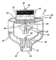
- FIG. 1 is an elevational view, partially in section, of an example of an irrigation device embodying features of the present invention.
- FIG. 2 is a perspective view depicting an example of a rotor assembly of an electric generator incorporated in the irrigation device of FIG. 1 .
- FIG. 3 is a perspective view depicting an example of a stator assembly of an electric generator incorporated in the irrigation device of FIG. 1 .
- the present invention electricity generating irrigation device improves upon existing electricity generating irrigation devices by positioning the mechanism which drives the rotor of the generator within the atmosphere. Positioning the rotor driving mechanism within the atmosphere causes little or no impairment to the distribution area of the sprinkler as compared to similar irrigation devices which do not include the generator.
- the rotor driving mechanism is a rotary deflector (FIG. 1 ).
- the rotor driving mechanism is a rotatable arm (not shown).
- FIG. 1 depicts a sprinkler 20 of the present invention.
- the sprinkler includes a nozzle 22 which couples to a fluid conduit, such as a pipe, tube or hose (not shown).
- the sprinkler also includes a rotary deflector 26 positioned downstream from the nozzle and an electric generator 28 coupled to the rotary deflector.
- a frame 30 supports the nozzle 22 and the electric generator 28 and couples the electric generator to the nozzle.
- the nozzle 22 includes a fluid inlet portion 32 including an inlet orifice 34 .
- the fluid inlet portion 32 may also include coupling means for coupling the nozzle to the fluid conduit.
- a fluid outlet portion 38 of the nozzle 22 may include an outlet orifice 40 sized smaller than the inlet orifice such that the fluid velocity increases as the fluid flows through the nozzle.
- the outlet orifice may be about the same size as the inlet orifice or larger than the outlet orifice. The outlet orifice directs the source of the fluid under pressure into an atmospheric condition in a stream.
- the fluid stream includes a generally vertically extending axis, while in other embodiments of the invention the fluid stream may include an axis extending in other directions as the configuration dictates.
- the outlet orifice of the nozzle is positioned proximate the rotary deflector 26 and the inlet orifice of the nozzle is positioned further from the rotary deflector than the outlet orifice.
- the rotary deflector 26 is positioned within the atmosphere.
- the rotary deflector 26 is mounted for rotational movement about a rotational axis.
- the rotational axis of the rotary deflector 26 is substantially coaxially aligned with the axis of the fluid stream which exits from the outlet orifice 40 of the nozzle 22 .
- the rotational axis of the rotary deflector 26 may be offset from the axis of the fluid stream and/or at an angle to the axis of the fluid stream.
- the rotary deflector 26 includes fluid stream engagement means configured to establish a reactionary force component acting on the rotary deflector in a direction tangential to the rotational axis of the rotary deflector 26 .
- the reactionary force effects rotational movement of the rotary deflector about its rotational axis.
- the rotary deflector includes a flow director channel 44 , for engaging the fluid stream.
- the fluid stream engagement means, such as the flow director channel 44 , of the rotary deflector 26 may convert the fluid stream into a spray moving radially away from the rotary deflector.
- the rotary deflector 26 is mounted to a shaft 48 .
- the shaft may extend axially from the rotary deflector body and away from the nozzle. The shaft is coupled to the rotary deflector through methods which are well known in the art.
- the shaft 48 functions as an axle for rotating a rotor assembly portion 52 of the electric generator 28 about the axis of the shaft.
- the electric generator is positioned within an electric generator housing 50 .
- the electric generator housing 50 may include a substantially open end 54 and a substantially closed end 56 .
- the open end 54 of the generator housing 50 opens to an aperture 58 which houses the rotor assembly 52 and a stator assembly portion 60 of the electric generator.
- the aperture may include a longitudinal axis which is substantially coaxially aligned with the axis of the shaft.
- the electric generator 28 may be of any suitable configuration which is well known in the art.
- one embodiment of the invention includes an electric generator with the rotor assembly having a permanent magnet member 62 secured axially to the shaft 48 .
- the permanent magnet member may include a plurality of circumferentially-spaced openings 64 formed therein, proximate the periphery of the permanent magnet member, with a magnet 66 positioned in each of the openings.
- the openings 64 in the permanent magnet member 62 and the magnets 66 each include a cylindrical shape.
- the stator assembly 60 may be fixedly positioned within the aperture of the generator housing 50 .
- the stator assembly 60 may include a bobbin 68 having a coil 70 of a conductive metallic wire, such as a copper wire, wound upon the bobbin.
- the center of the bobbin may include an open hub 72 through which the shaft 48 extends.
- a bushing or bearing 74 may be mounted inside the hub 72 to facilitate alignment of the shaft and to reduce friction between the shaft and the bobbin 68 .
- the stator assembly 60 may be secured to the aperture 58 of the generator housing 50 through means well known in the art.
- the electricity generating irrigation device 10 is coupled to a fluid conduit (not shown), such as a pipe.
- a fluid such as water, enters the fluid inlet portion 32 of the nozzle 22 , exits the outlet orifice 40 of the nozzle, and enters the atmosphere.
- the fluid then contacts the rotary deflector 26 in such manner to establish the reactionary force component to effect rotational movement of the rotary deflector about its rotational axis.
- the fluid exiting through the outlet orifice 40 of the nozzle 22 enters the deflector channel 44 of the rotary deflector 26 and issues out and away from the rotary deflector in a spray pattern.
- the nozzle 22 , frame 30 and generator housing 50 may be formed from a plastic material, such as nylon, and molded together into a single unit. Alternatively, the nozzle, frame and generator housing may be formed separately and coupled together. Further, the nozzle, frame and generator housing may be made by other methods well known in the art or from other materials well known in the art.
- the shaft 48 may be made from a metallic material, such as stainless steel, or other suitable materials well known in the art.
- rotation of the rotary deflector 26 causes the shaft 48 to rotate, which in turn causes the rotor assembly 52 to rotate.
- an electrical current is generated in the coil 70 in the stator assembly 60 .
- the generated electricity may by conducted out of the irrigation device 10 via wires (not shown) coupled to the coil 70 and delivered by the wires to electrical components (not shown) for storage or use.
- the fluid distribution pattern such as a spray pattern, created by the irrigation device 10 of the present invention experiences little or no impairment, as compared to devices which include an impeller positioned within the fluid conduit to turn the rotor of the generator.
- the electric generator 28 tends to decrease the rotation speed of the rotary deflector 26
- the throw distance of the distribution pattern may be increased by reducing the rooster tail effect of the distribution pattern caused by a quicker rotation of the rotary deflector.
Landscapes
- Connection Of Motors, Electrical Generators, Mechanical Devices, And The Like (AREA)
- Nozzles (AREA)
Abstract
Description
Claims (20)
Priority Applications (8)
| Application Number | Priority Date | Filing Date | Title |
|---|---|---|---|
| US10/441,374 US6864591B2 (en) | 2003-05-20 | 2003-05-20 | Sprinkler activated generator |
| AU2004241277A AU2004241277A1 (en) | 2003-05-20 | 2004-05-19 | Sprinkler activated generator |
| ES04752625T ES2391972T3 (en) | 2003-05-20 | 2004-05-19 | Spray Activated Generator |
| MXPA05012478A MXPA05012478A (en) | 2003-05-20 | 2004-05-19 | Sprinkler activated generator. |
| PT04752625T PT1625654E (en) | 2003-05-20 | 2004-05-19 | Sprinkler activated generator |
| EP04752625A EP1625654B1 (en) | 2003-05-20 | 2004-05-19 | Sprinkler activated generator |
| PCT/US2004/015636 WO2004103570A2 (en) | 2003-05-20 | 2004-05-19 | Sprinkler activated generator |
| CY20121100883T CY1114184T1 (en) | 2003-05-20 | 2012-09-27 | SPRINKLER-ACTIVATED GENERATOR |
Applications Claiming Priority (1)
| Application Number | Priority Date | Filing Date | Title |
|---|---|---|---|
| US10/441,374 US6864591B2 (en) | 2003-05-20 | 2003-05-20 | Sprinkler activated generator |
Publications (2)
| Publication Number | Publication Date |
|---|---|
| US20040232701A1 US20040232701A1 (en) | 2004-11-25 |
| US6864591B2 true US6864591B2 (en) | 2005-03-08 |
Family
ID=33449977
Family Applications (1)
| Application Number | Title | Priority Date | Filing Date |
|---|---|---|---|
| US10/441,374 Expired - Lifetime US6864591B2 (en) | 2003-05-20 | 2003-05-20 | Sprinkler activated generator |
Country Status (8)
| Country | Link |
|---|---|
| US (1) | US6864591B2 (en) |
| EP (1) | EP1625654B1 (en) |
| AU (1) | AU2004241277A1 (en) |
| CY (1) | CY1114184T1 (en) |
| ES (1) | ES2391972T3 (en) |
| MX (1) | MXPA05012478A (en) |
| PT (1) | PT1625654E (en) |
| WO (1) | WO2004103570A2 (en) |
Cited By (18)
| Publication number | Priority date | Publication date | Assignee | Title |
|---|---|---|---|---|
| US20070126237A1 (en) * | 2005-12-06 | 2007-06-07 | Jung-Huang Liao | Fluid-driven lighting device |
| WO2007132973A1 (en) * | 2006-05-12 | 2007-11-22 | Soon Nam Byun | Hydraulic generation sprinkler for refuge leading |
| US20090102193A1 (en) * | 2007-10-22 | 2009-04-23 | Murphy Liam C | Fluid-driven electric generator for operatively connecting to a conduct carrying a fluid |
| US20090276952A1 (en) * | 2008-05-09 | 2009-11-12 | Wooten Timothy R | Power generating water jet |
| US20100033015A1 (en) * | 2008-08-07 | 2010-02-11 | Techstream Control Systems, Inc | Unitized Electric Generator and Storage System - Combined Hydro Turbine and Solar Powered Electrical Storage System |
| US20100071915A1 (en) * | 2008-09-22 | 2010-03-25 | Nelson Caldani | Fire sprinkler illumination system |
| US20110012359A1 (en) * | 2009-07-14 | 2011-01-20 | Industrial Technology Research Institute | Swirly fluid sprinkler |
| US20110012355A1 (en) * | 2009-07-14 | 2011-01-20 | Industrial Technology Research Institute | Fluid Whirl Lighting Apparatus |
| US20110064626A1 (en) * | 2007-10-08 | 2011-03-17 | Gary Andrew Kennedy | Energy generation methods and systems for swimming pools and other vessels with recirculating fluid |
| US20110071698A1 (en) * | 2009-09-23 | 2011-03-24 | Zurn Industries, Llc | Flush Valve Hydrogenerator |
| US20110226361A1 (en) * | 2010-03-16 | 2011-09-22 | Zodiac Pool Systems, Inc. | Idler mechanisms for hydraulic devices |
| WO2014068594A2 (en) | 2012-10-30 | 2014-05-08 | Jain Irrigation Systems Limited | Motion control system and method with energy harvesting |
| US8733672B2 (en) | 2010-11-24 | 2014-05-27 | Rain Bird Corporation | Rotary irrigation sprinkler with an electromagnetic drive system |
| WO2016071924A3 (en) * | 2014-11-05 | 2016-08-04 | Jain Irrigation Systems Limited | Embedded sprinkler activated generator |
| WO2016071923A3 (en) * | 2014-11-04 | 2016-08-25 | Jain Irrigation Systems Limited | Method of integrated flow control for the sprinkler activated generator |
| US9587687B2 (en) | 2015-01-14 | 2017-03-07 | Nelson Irrigation Corporation | Viscous rotational speed control device |
| US9657790B2 (en) | 2015-01-14 | 2017-05-23 | Nelson Irrigation Corporation | Viscous rotational speed control device |
| US20200070187A1 (en) * | 2018-11-05 | 2020-03-05 | Xcad Usa | Eddy current sprinkler dampener |
Families Citing this family (4)
| Publication number | Priority date | Publication date | Assignee | Title |
|---|---|---|---|---|
| BRPI0910143B1 (en) * | 2008-06-30 | 2022-04-26 | Naandanjain Irrigation Ltd | rotating water sprinkler |
| DE102012002940A1 (en) * | 2012-02-16 | 2013-08-22 | Udo Tartler | Device for spraying liquid, in particular on a surface |
| US10232388B2 (en) | 2017-03-08 | 2019-03-19 | NaanDanJain Irrigation Ltd. | Multiple orientation rotatable sprinkler |
| US20220368195A1 (en) * | 2021-05-14 | 2022-11-17 | Rain Bird Corporation | Self-powered irrigation systems, generator systems and methods of controlling irrigation |
Citations (17)
| Publication number | Priority date | Publication date | Assignee | Title |
|---|---|---|---|---|
| US3642204A (en) * | 1969-11-28 | 1972-02-15 | Edward W Mccloskey | Waterflow-controlling apparatus for an automatic irrigation system |
| US3845291A (en) * | 1974-02-08 | 1974-10-29 | Titan Tool And Die Co Inc | Water powered swimming pool light |
| USRE31023E (en) | 1975-04-11 | 1982-09-07 | Advanced Decision Handling, Inc. | Highly automated agricultural production system |
| US4352025A (en) * | 1980-11-17 | 1982-09-28 | Troyen Harry D | System for generation of electrical power |
| US4488055A (en) * | 1982-03-10 | 1984-12-11 | James Toyama | Fluid pipe generator |
| US4522338A (en) | 1982-12-30 | 1985-06-11 | Williams Christopher G | Irrigation system |
| US4564889A (en) | 1982-11-10 | 1986-01-14 | Bolson Frank J | Hydro-light |
| US4616298A (en) | 1985-12-26 | 1986-10-07 | Bolson Frank J | Water-powered light |
| US4660766A (en) | 1985-09-18 | 1987-04-28 | Nelson Irrigation Corporation | Rotary sprinkler head |
| US4731545A (en) | 1986-03-14 | 1988-03-15 | Desai & Lerner | Portable self-contained power conversion unit |
| US4838310A (en) | 1988-03-28 | 1989-06-13 | Motorola, Inc. | Hydroelectrically powered, remotely controlled irrigation system |
| US4877189A (en) | 1987-05-18 | 1989-10-31 | Williams Christopher G | Irrigation system |
| US4920465A (en) | 1988-11-15 | 1990-04-24 | Alopex Industries, Inc. | Floating fountain device |
| US5140254A (en) * | 1990-10-10 | 1992-08-18 | David Katzman | Shower accessory |
| FR2725502A1 (en) * | 1994-10-05 | 1996-04-12 | Mitsubishi Heavy Ind Ltd | Artificial snow fall machine |
| US6336596B1 (en) * | 1997-03-25 | 2002-01-08 | Dan Mamtirim | Electrically operated sprinkler |
| US6798080B1 (en) * | 1999-10-05 | 2004-09-28 | Access Business Group International | Hydro-power generation for a water treatment system and method of supplying electricity using a flow of liquid |
Family Cites Families (3)
| Publication number | Priority date | Publication date | Assignee | Title |
|---|---|---|---|---|
| US4951915A (en) * | 1990-01-10 | 1990-08-28 | Piao Lin C | Electronic water flow control device |
| DE4327199A1 (en) * | 1993-08-13 | 1995-02-16 | Runolt Holz | Sprinkler head with illumination |
| US5427350A (en) * | 1994-05-31 | 1995-06-27 | Rinkewich; Isaac | Electrically-operated control valve and water distribution system including same |
-
2003
- 2003-05-20 US US10/441,374 patent/US6864591B2/en not_active Expired - Lifetime
-
2004
- 2004-05-19 WO PCT/US2004/015636 patent/WO2004103570A2/en active Application Filing
- 2004-05-19 AU AU2004241277A patent/AU2004241277A1/en not_active Abandoned
- 2004-05-19 PT PT04752625T patent/PT1625654E/en unknown
- 2004-05-19 EP EP04752625A patent/EP1625654B1/en active Active
- 2004-05-19 MX MXPA05012478A patent/MXPA05012478A/en active IP Right Grant
- 2004-05-19 ES ES04752625T patent/ES2391972T3/en active Active
-
2012
- 2012-09-27 CY CY20121100883T patent/CY1114184T1/en unknown
Patent Citations (17)
| Publication number | Priority date | Publication date | Assignee | Title |
|---|---|---|---|---|
| US3642204A (en) * | 1969-11-28 | 1972-02-15 | Edward W Mccloskey | Waterflow-controlling apparatus for an automatic irrigation system |
| US3845291A (en) * | 1974-02-08 | 1974-10-29 | Titan Tool And Die Co Inc | Water powered swimming pool light |
| USRE31023E (en) | 1975-04-11 | 1982-09-07 | Advanced Decision Handling, Inc. | Highly automated agricultural production system |
| US4352025A (en) * | 1980-11-17 | 1982-09-28 | Troyen Harry D | System for generation of electrical power |
| US4488055A (en) * | 1982-03-10 | 1984-12-11 | James Toyama | Fluid pipe generator |
| US4564889A (en) | 1982-11-10 | 1986-01-14 | Bolson Frank J | Hydro-light |
| US4522338A (en) | 1982-12-30 | 1985-06-11 | Williams Christopher G | Irrigation system |
| US4660766A (en) | 1985-09-18 | 1987-04-28 | Nelson Irrigation Corporation | Rotary sprinkler head |
| US4616298A (en) | 1985-12-26 | 1986-10-07 | Bolson Frank J | Water-powered light |
| US4731545A (en) | 1986-03-14 | 1988-03-15 | Desai & Lerner | Portable self-contained power conversion unit |
| US4877189A (en) | 1987-05-18 | 1989-10-31 | Williams Christopher G | Irrigation system |
| US4838310A (en) | 1988-03-28 | 1989-06-13 | Motorola, Inc. | Hydroelectrically powered, remotely controlled irrigation system |
| US4920465A (en) | 1988-11-15 | 1990-04-24 | Alopex Industries, Inc. | Floating fountain device |
| US5140254A (en) * | 1990-10-10 | 1992-08-18 | David Katzman | Shower accessory |
| FR2725502A1 (en) * | 1994-10-05 | 1996-04-12 | Mitsubishi Heavy Ind Ltd | Artificial snow fall machine |
| US6336596B1 (en) * | 1997-03-25 | 2002-01-08 | Dan Mamtirim | Electrically operated sprinkler |
| US6798080B1 (en) * | 1999-10-05 | 2004-09-28 | Access Business Group International | Hydro-power generation for a water treatment system and method of supplying electricity using a flow of liquid |
Cited By (28)
| Publication number | Priority date | Publication date | Assignee | Title |
|---|---|---|---|---|
| US20070126237A1 (en) * | 2005-12-06 | 2007-06-07 | Jung-Huang Liao | Fluid-driven lighting device |
| WO2007132973A1 (en) * | 2006-05-12 | 2007-11-22 | Soon Nam Byun | Hydraulic generation sprinkler for refuge leading |
| US20110064626A1 (en) * | 2007-10-08 | 2011-03-17 | Gary Andrew Kennedy | Energy generation methods and systems for swimming pools and other vessels with recirculating fluid |
| US8092675B2 (en) | 2007-10-08 | 2012-01-10 | Zodiac Group Australia Pty. Ltd. | Energy generation methods and systems for swimming pools and other vessels with recirculating fluid |
| US20090102193A1 (en) * | 2007-10-22 | 2009-04-23 | Murphy Liam C | Fluid-driven electric generator for operatively connecting to a conduct carrying a fluid |
| US20090276952A1 (en) * | 2008-05-09 | 2009-11-12 | Wooten Timothy R | Power generating water jet |
| US20100033015A1 (en) * | 2008-08-07 | 2010-02-11 | Techstream Control Systems, Inc | Unitized Electric Generator and Storage System - Combined Hydro Turbine and Solar Powered Electrical Storage System |
| US20100071915A1 (en) * | 2008-09-22 | 2010-03-25 | Nelson Caldani | Fire sprinkler illumination system |
| US8278775B2 (en) | 2009-07-14 | 2012-10-02 | Industrial Technology Research Institute | Swirly fluid sprinkler |
| US20110012359A1 (en) * | 2009-07-14 | 2011-01-20 | Industrial Technology Research Institute | Swirly fluid sprinkler |
| US20110012355A1 (en) * | 2009-07-14 | 2011-01-20 | Industrial Technology Research Institute | Fluid Whirl Lighting Apparatus |
| US8319367B2 (en) | 2009-07-14 | 2012-11-27 | Industrial Technology Research Institute | Fluid whirl lighting apparatus |
| US8698333B2 (en) | 2009-09-23 | 2014-04-15 | Zurn Industries, Llc | Flush valve hydrogenerator |
| US20110071698A1 (en) * | 2009-09-23 | 2011-03-24 | Zurn Industries, Llc | Flush Valve Hydrogenerator |
| US20110226361A1 (en) * | 2010-03-16 | 2011-09-22 | Zodiac Pool Systems, Inc. | Idler mechanisms for hydraulic devices |
| US9163421B2 (en) | 2010-03-16 | 2015-10-20 | Zodiac Pool Systems, Inc. | Idler mechanisms for hydraulic devices |
| US8733672B2 (en) | 2010-11-24 | 2014-05-27 | Rain Bird Corporation | Rotary irrigation sprinkler with an electromagnetic drive system |
| WO2014068594A2 (en) | 2012-10-30 | 2014-05-08 | Jain Irrigation Systems Limited | Motion control system and method with energy harvesting |
| WO2016071923A3 (en) * | 2014-11-04 | 2016-08-25 | Jain Irrigation Systems Limited | Method of integrated flow control for the sprinkler activated generator |
| US10576481B2 (en) * | 2014-11-04 | 2020-03-03 | Jain Irrigation Systems Limited | Method of integrated flow control for the sprinkler activated generator |
| WO2016071924A3 (en) * | 2014-11-05 | 2016-08-04 | Jain Irrigation Systems Limited | Embedded sprinkler activated generator |
| US20180320653A1 (en) * | 2014-11-05 | 2018-11-08 | Jain Irrigation Systems Limited | Embedded sprinkler activated generator |
| US9587687B2 (en) | 2015-01-14 | 2017-03-07 | Nelson Irrigation Corporation | Viscous rotational speed control device |
| US9657790B2 (en) | 2015-01-14 | 2017-05-23 | Nelson Irrigation Corporation | Viscous rotational speed control device |
| US9995352B2 (en) | 2015-01-14 | 2018-06-12 | Nelson Irrigation Corporation | Viscous rotational speed control device |
| US10107342B2 (en) | 2015-01-14 | 2018-10-23 | Nelson Irrigation Corporation | Viscous rotational speed control device with fluid circuit |
| US20200070187A1 (en) * | 2018-11-05 | 2020-03-05 | Xcad Usa | Eddy current sprinkler dampener |
| US11890634B2 (en) * | 2018-11-05 | 2024-02-06 | Xcad Usa | Eddy current sprinkler dampener |
Also Published As
| Publication number | Publication date |
|---|---|
| ES2391972T3 (en) | 2012-12-03 |
| MXPA05012478A (en) | 2006-05-25 |
| PT1625654E (en) | 2012-10-04 |
| EP1625654A2 (en) | 2006-02-15 |
| WO2004103570A2 (en) | 2004-12-02 |
| WO2004103570A3 (en) | 2005-06-30 |
| EP1625654B1 (en) | 2012-08-01 |
| CY1114184T1 (en) | 2016-08-31 |
| AU2004241277A1 (en) | 2004-12-02 |
| EP1625654A4 (en) | 2008-11-19 |
| US20040232701A1 (en) | 2004-11-25 |
Similar Documents
| Publication | Publication Date | Title |
|---|---|---|
| US6864591B2 (en) | Sprinkler activated generator | |
| US7233078B2 (en) | Miniature hydro-power generation system | |
| KR100728421B1 (en) | Hydro-power generation for a water treatment system | |
| CN101910617B (en) | Miniature hydro-power generation system | |
| JP5021696B2 (en) | Hydroelectric power generation system and method for generating electric power by hydroelectric power generation system | |
| TWI437162B (en) | Faucet with generator | |
| JP6873084B2 (en) | Impeller for electrostatic spray gun | |
| US3221992A (en) | Coating material motive agent atomizer head | |
| RU2644912C2 (en) | Alternating-current generator for electrostatic spray gun | |
| EP1041699A3 (en) | Electric motor or generator | |
| US20150060579A1 (en) | Electrostatic Spray System | |
| WO2008100527A1 (en) | Fluid distributing device and method | |
| US3369758A (en) | Liquid discharge device | |
| JP2008050852A (en) | Water faucet fitting | |
| JP2004364441A (en) | Rotating apparatus, and generator and pump using the same | |
| CN210230331U (en) | High-pressure rotary nozzle mounting head | |
| JP7439566B2 (en) | faucet generator | |
| JP3097865U (en) | Improved spray header | |
| EP1795746A2 (en) | Miniature hydro-power generation system | |
| CN115855188A (en) | Pulse counter and water purifier | |
| TWM624769U (en) | Tube type axial flow power generator | |
| JP2008245381A (en) | Power generator for faucet | |
| CN109384289A (en) | Magnetic water device | |
| JP2003117455A (en) | Speed sprayer | |
| KR20030014491A (en) | Sealing apparatus using compressed air |
Legal Events
| Date | Code | Title | Description |
|---|---|---|---|
| FPAY | Fee payment |
Year of fee payment: 4 |
|
| REMI | Maintenance fee reminder mailed | ||
| REMI | Maintenance fee reminder mailed | ||
| FEPP | Fee payment procedure |
Free format text: PETITION RELATED TO MAINTENANCE FEES GRANTED (ORIGINAL EVENT CODE: PMFG); ENTITY STATUS OF PATENT OWNER: SMALL ENTITY Free format text: PETITION RELATED TO MAINTENANCE FEES FILED (ORIGINAL EVENT CODE: PMFP); ENTITY STATUS OF PATENT OWNER: SMALL ENTITY |
|
| LAPS | Lapse for failure to pay maintenance fees | ||
| REIN | Reinstatement after maintenance fee payment confirmed | ||
| FP | Lapsed due to failure to pay maintenance fee |
Effective date: 20130308 |
|
| PRDP | Patent reinstated due to the acceptance of a late maintenance fee |
Effective date: 20130606 |
|
| FPAY | Fee payment |
Year of fee payment: 8 |
|
| STCF | Information on status: patent grant |
Free format text: PATENTED CASE |
|
| SULP | Surcharge for late payment | ||
| FPAY | Fee payment |
Year of fee payment: 12 |