US6882653B1 - Gateway system having controller and signal processor for interconnecting IP network and telephone network and method for controlling alternative routing at the time of fault of gateway system - Google Patents
Gateway system having controller and signal processor for interconnecting IP network and telephone network and method for controlling alternative routing at the time of fault of gateway system Download PDFInfo
- Publication number
- US6882653B1 US6882653B1 US09/651,100 US65110000A US6882653B1 US 6882653 B1 US6882653 B1 US 6882653B1 US 65110000 A US65110000 A US 65110000A US 6882653 B1 US6882653 B1 US 6882653B1
- Authority
- US
- United States
- Prior art keywords
- fault
- network
- controller
- telephone network
- detected
- Prior art date
- Legal status (The legal status is an assumption and is not a legal conclusion. Google has not performed a legal analysis and makes no representation as to the accuracy of the status listed.)
- Expired - Lifetime, expires
Links
- 238000000034 method Methods 0.000 title claims description 188
- 230000004044 response Effects 0.000 claims description 44
- 238000012544 monitoring process Methods 0.000 claims description 26
- 238000001514 detection method Methods 0.000 claims description 20
- 230000005540 biological transmission Effects 0.000 claims description 14
- 238000004891 communication Methods 0.000 abstract description 10
- 238000011144 upstream manufacturing Methods 0.000 abstract description 2
- 108091006146 Channels Proteins 0.000 description 63
- 238000010586 diagram Methods 0.000 description 32
- 230000006870 function Effects 0.000 description 19
- 238000007726 management method Methods 0.000 description 18
- 230000000694 effects Effects 0.000 description 9
- 230000011664 signaling Effects 0.000 description 9
- 230000000903 blocking effect Effects 0.000 description 7
- 238000011084 recovery Methods 0.000 description 5
- 238000013459 approach Methods 0.000 description 3
- 208000003443 Unconsciousness Diseases 0.000 description 2
- 230000005055 memory storage Effects 0.000 description 2
- 238000012545 processing Methods 0.000 description 2
- 238000012546 transfer Methods 0.000 description 2
- 230000003213 activating effect Effects 0.000 description 1
- 238000006243 chemical reaction Methods 0.000 description 1
- 230000001934 delay Effects 0.000 description 1
- 238000005516 engineering process Methods 0.000 description 1
- 238000005259 measurement Methods 0.000 description 1
- 230000001360 synchronised effect Effects 0.000 description 1
Images


Classifications
-
- H—ELECTRICITY
- H04—ELECTRIC COMMUNICATION TECHNIQUE
- H04M—TELEPHONIC COMMUNICATION
- H04M3/00—Automatic or semi-automatic exchanges
- H04M3/08—Indicating faults in circuits or apparatus
- H04M3/12—Marking faulty circuits "busy"; Enabling equipment to disengage itself from faulty circuits ; Using redundant circuits; Response of a circuit, apparatus or system to an error
-
- H—ELECTRICITY
- H04—ELECTRIC COMMUNICATION TECHNIQUE
- H04L—TRANSMISSION OF DIGITAL INFORMATION, e.g. TELEGRAPHIC COMMUNICATION
- H04L41/00—Arrangements for maintenance, administration or management of data switching networks, e.g. of packet switching networks
- H04L41/06—Management of faults, events, alarms or notifications
- H04L41/0654—Management of faults, events, alarms or notifications using network fault recovery
- H04L41/0663—Performing the actions predefined by failover planning, e.g. switching to standby network elements
-
- H—ELECTRICITY
- H04—ELECTRIC COMMUNICATION TECHNIQUE
- H04L—TRANSMISSION OF DIGITAL INFORMATION, e.g. TELEGRAPHIC COMMUNICATION
- H04L41/00—Arrangements for maintenance, administration or management of data switching networks, e.g. of packet switching networks
- H04L41/28—Restricting access to network management systems or functions, e.g. using authorisation function to access network configuration
-
- H—ELECTRICITY
- H04—ELECTRIC COMMUNICATION TECHNIQUE
- H04L—TRANSMISSION OF DIGITAL INFORMATION, e.g. TELEGRAPHIC COMMUNICATION
- H04L45/00—Routing or path finding of packets in data switching networks
- H04L45/22—Alternate routing
-
- H—ELECTRICITY
- H04—ELECTRIC COMMUNICATION TECHNIQUE
- H04L—TRANSMISSION OF DIGITAL INFORMATION, e.g. TELEGRAPHIC COMMUNICATION
- H04L45/00—Routing or path finding of packets in data switching networks
- H04L45/28—Routing or path finding of packets in data switching networks using route fault recovery
-
- H—ELECTRICITY
- H04—ELECTRIC COMMUNICATION TECHNIQUE
- H04L—TRANSMISSION OF DIGITAL INFORMATION, e.g. TELEGRAPHIC COMMUNICATION
- H04L47/00—Traffic control in data switching networks
- H04L47/10—Flow control; Congestion control
-
- H—ELECTRICITY
- H04—ELECTRIC COMMUNICATION TECHNIQUE
- H04L—TRANSMISSION OF DIGITAL INFORMATION, e.g. TELEGRAPHIC COMMUNICATION
- H04L69/00—Network arrangements, protocols or services independent of the application payload and not provided for in the other groups of this subclass
- H04L69/40—Network arrangements, protocols or services independent of the application payload and not provided for in the other groups of this subclass for recovering from a failure of a protocol instance or entity, e.g. service redundancy protocols, protocol state redundancy or protocol service redirection
-
- H—ELECTRICITY
- H04—ELECTRIC COMMUNICATION TECHNIQUE
- H04M—TELEPHONIC COMMUNICATION
- H04M7/00—Arrangements for interconnection between switching centres
- H04M7/12—Arrangements for interconnection between switching centres for working between exchanges having different types of switching equipment, e.g. power-driven and step by step or decimal and non-decimal
- H04M7/1205—Arrangements for interconnection between switching centres for working between exchanges having different types of switching equipment, e.g. power-driven and step by step or decimal and non-decimal where the types of switching equipement comprises PSTN/ISDN equipment and switching equipment of networks other than PSTN/ISDN, e.g. Internet Protocol networks
- H04M7/125—Details of gateway equipment
-
- H—ELECTRICITY
- H04—ELECTRIC COMMUNICATION TECHNIQUE
- H04L—TRANSMISSION OF DIGITAL INFORMATION, e.g. TELEGRAPHIC COMMUNICATION
- H04L63/00—Network architectures or network communication protocols for network security
- H04L63/08—Network architectures or network communication protocols for network security for authentication of entities
Definitions
- the present invention relates to a method for connecting a telephone network and an IP network (internet protocol network), a method for detecting faults and a method for controlling alternative routing.
- IP network internet protocol network
- the present invention relates to a method for connecting a telephone network and an IP network in an internet gateway system constituted by a signaling gateway/media gateway controller and a gateway device, the method detecting a fault at an IP network interface of the gateway device, blocking the line to the upstream telephone network and instructing alternative routing.
- Presently available measures to detect a fault between nodes of a telephone network include monitoring of the state of a common line signal link between opposite at an interface between networks, monitoring of frame bits of a communication line and monitoring of the state of a circuit between a network and a user terminal at a user/network interface.
- a fault of a common line signal can be notified and an instruction can be made on alternative routing utilizing a message transfer part (MTP) of a common channel signaling #7 (CCS 7 ) at an interface between networks; blocking of a communication line can be instructed utilizing a blocking signal in an ISDN user part (ISUP); and an instruction on alternative routing can be made using a redirection procedure according to the TTC (Telecommunication Technology Committee) specifications or using a pivot procedure according to the ITU-T (International Telecommunication Union) recommendations and TTC specifications.
- MTP message transfer part
- CCS 7 common channel signaling #7
- ISUP ISDN user part
- Measures to detect a fault between nodes of an IP network include a method in which congestion of traffic or a fault between opposite nodes is detected by exchanging a message such as “ping” according to the ICMP (Internet Control Message Protocol) defined in the RFC (Requests for Comments) of the IETF (Internet Engineering Task Force) between the opposite nodes and a method in which the state of the apparatus at each of nodes forming a network is collected using a network manager such as an SNMP (Simple Network Management Protocol) manager or gate keeper defined in the RFC1157.
- ICMP Internet Control Message Protocol
- RFC Requests for Comments
- IETF Internet Engineering Task Force
- a method is used in which routing information is distributed to each of nodes forming a network using a router or a network manager such as an SNMP manager or gate keeper according to a dynamic routing protocol such as the RIP (Routing Information Protocol) defined in the RFC2453, the OSPF (Open Shortest Path Fast) defined I the RFC2328 or the BGP (Border Gateway Protocol) defined in the RFC1771.
- RIP Ring Information Protocol
- OSPF Open Shortest Path Fast
- BGP Border Gateway Protocol
- a gateway system comprising a plurality of gateway devices that share a plurality of lines with a single or a plurality of called numbers
- the above-described methods are available for detecting faults in each of the telephone network and IP network and for controlling alternative routing.
- incoming calls are accepted for a group of lines that utilize the routing channel having a fault in the IP network in spite of the fact that there is a group of lines over which incoming calls with the same called number can be properly received, which may cause call loss and reduction in the service quality of communication.
- a gateway system is provided with a function of monitoring the number of packets held in the gateway system and internal resources of the gateway system and detecting a state of faults in the gateway system and an access path to an IP network so as to detect the state of a line for connecting the telephone network to the IP network.
- the gateway system has a function of receiving information on faults in an IP network from a gate keeper or a network manager or inquiring the same to acquire information on whether transmission of packets to each of nodes such as servers and a router that form the IP network is enabled or disabled, and detecting the state of a line for connecting the telephone network to the IP network.
- the gateway system also has a function of detecting network faults associated with connections from the gateway system to an IP network by analyzing information of a notification of disabled routing to a particular route received from each of nodes such as a router that form an IP network.
- a function of notifying a telephone network of the fact that the use of a line is disabled depending on the frequency of faults when fault detection is performed for each call and notifying of cancellation of disabled use There is also provided a function of notifying of a telephone network of the fact that a part of the lines are disabled depending on the frequency of faults when fault detection is performed for each call, and monitoring the frequency of faults of incoming calls to the remaining lines to detect recovery from the faults, thereby notifying of the telephone network of cancellation of disabled use with utilizing a timer.
- the gateway system and the telephone network described above supervise called numbers which can be routed to each device in the gateway system among the lines contained therein, and the gateway system is provided with a function of instructing the telephone network of the called number that allows alternative routing to a usable line to allow the telephone network to actively perform alternative routing. There is also provided a function of allowing alternative routing to a usable line for each call utilizing an alternative routing function using an SPC provided in the telephone network by instructing the telephone network of the fact the call can be alternatively routed.
- FIG. 1 is a diagram showing a configuration for internetwork connection between a telephone network and an IP network through a gateway system according to the invention and procedures for access from a primary signal processor of the gateway system to servers.
- FIG. 2 is a diagram showing a configuration for internetwork connection between a telephone network and an IP network through a gateway system according to the invention and procedures for access from a primary signal processor of the gateway system to servers.
- FIG. 3 is a diagram showing a configuration of a controller according to the invention.
- FIG. 4 is a diagram showing a configuration of a primary signal processor according to the invention.
- FIG. 5 is a diagram showing cases of faults at internetwork connection between a telephone line and an IP network through the gateway system according to the invention.
- FIG. 6 is a diagram showing a flow of selection of methods for instructing alternative routing for the cases of faults at internetwork connection between a telephone line and an IP network through the gateway system according to the invention.
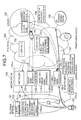
- FIG. 7 is a diagram showing procedures according to the invention for detecting a fault in a case 2 using a method 3 and performing alternative routing according to an alternative routing instructing method 1 .
- FIG. 8 is a diagram showing a sequence according to the invention for detecting a fault in the case 2 using the method 3 and performing alternative routing according to the alternative routing instructing method 1 .
- FIG. 9 is a diagram showing procedures according to the invention for detecting a fault in a case 4 using the method 3 and performing alternative routing according to an alternative routing instructing method 2 .
- FIG. 10 is a diagram showing a sequence according to the invention for detecting a fault in the case 4 using the method 3 and performing alternative routing according to the alternative routing instructing method 2 .
- FIG. 11 is a diagram showing procedures according to the invention taken in a device for detecting a fault in the case 4 using the method 3 .
- FIG. 12 is a diagram showing procedures according to the invention for detecting a fault in a case 5 using the method 3 and performing alternative routing according to an alternative routing instructing method 3 .
- FIG. 13 is a diagram showing a sequence according to the invention for detecting a fault in the case 5 using the method 3 and performing alternative routing according to the alternative routing instructing method 3 .
- FIG. 14 is a diagram showing procedures according to the invention taken in a device for detecting a fault in the case 5 using the method 3 .
- FIG. 15 is a diagram showing procedures according to the invention for detecting a fault in the case 2 using a method 2 and performing alternative routing according to the alternative routing instructing method 3 .
- FIG. 16 is a diagram showing a sequence according to the invention for detecting a fault in the case 2 using the method 2 and performing alternative routing according to the alternative routing instructing method 3 .
- FIG. 17 is a diagram showing procedures according to the invention for detecting a fault in a case 3 using the method 2 and performing alternative routing according to an alternative routing instructing method 4 .
- FIG. 18 is a diagram showing a sequence according to the invention for detecting a fault in the case 3 using the method 2 and performing alternative routing according to the alternative routing instructing method 4 .
- FIG. 19 is a diagram showing a flow according to the invention for detecting a fault in the case 3 using the method 2 and performing alternative routing according to the alternative routing instructing method 4 .
- FIG. 20 is a diagram showing procedures according to the invention for detecting a fault in the case 3 using the method 2 and performing alternative routing according to an alternative routing instructing method 5 .
- FIG. 21 is a diagram showing a sequence according to the invention for detecting a fault in the case 3 using the method 2 and performing alternative routing according to the alternative routing instructing method 5 .
- FIG. 22 is a diagram showing a flow according to the invention for detecting a fault in the case 3 using the method 2 and performing alternative routing according to the alternative routing instructing method 5 .
- FIGS. 1 and 2 show an example of a configuration diagram of internetwork connection between a telephone network and an IP network through a gateway system according to the invention.
- Internetwork connection between a telephone network 101 and an IP network 102 is established through a gateway system 103 comprising controllers 110 - a and 110 - b , and stream controllers (primary signal processors) 120 - a and 120 - b.
- the IP network is formed by the gateway system, a LAN including the gateway system, a LAN including a server, and an internet network.
- the telephone network 101 and the controllers 110 - a and 110 - b are connected through a signal channel (D-channel) of a user/network interface of an ISDN or a common channel signaling #7 of an internetwork connection interface, and the telephone network 101 and the primary signal processors 120 a , 120 b , 110 - b are connected through the B-channel, H0-channel and H1-channel of the ISDN or a line interface such as an SDH (Synchronous Digital Hierarchy), 2M TTC, T1 or E1.
- Control signals from the telephone network 101 cause the controllers 110 - a and 110 - b to perform a control process of call processing signals, and the call control processing at the primary signal processors 120 - a , 120 - b and 110 - b .
- the controllers and the primary signal processors may be physically separated and, alternatively, a single apparatus may contain both of them like the controller 110 - b .
- a single controller ( 110 - a , 110 - b ) may control a plurality of primary signal processors such as the primary signal processor 120 - b which are separately provided.
- FIG. 1 shows a case in which a user 150 places a call to groups of lines contained in the primary signal processors 1 , 2 and 3 of the gateway system 103 with an incoming telephone number which is routed by the telephone network 101 and in which the call is routed to the lines contained in the primary signal processor 1 ( 120 - a ).
- a controller When a controller accepts a request for connection from the telephone network, either or both of the controller and a primary signal processor access authentication, accounting, and address management servers to perform acquisition of an access IP address, authentication of the user and the like and thereafter access an ISP network (internet service provider network) or another gateway system.
- ISP network Internet service provider network
- the RADIUS Remote Authentication Dial In User Service
- the IPCP Internet Protocol Control Protocol
- the IETF RFC1332 is used as means for acquiring an access IP address.
- FIG. 1 shows an example in which the controller 1 ( 110 - a ) controls the primary signal processor 1 ( 120 - a ) such that the primary signal processor 1 ( 120 - a ) accesses servers 130 to perform control and accesses an ISP network and another gateway system 140 (hereinafter simply referred to as “ISP network”) for a primary signal from the user who has placed a call.
- FIG. 2 shows an example in which the controller 110 - a establishes a control access to the servers 130 to control the primary signal processor 120 - a and establishes a control access to the ISP network 140 to establish an access for the primary signal from the primary signal processor 120 - a to the ISP network 140 .
- FIG. 3 is a configuration diagram of a controller of a gateway system.
- a controller 110 is constituted by primary hardware components, e.g., a processor 111 , a storage 116 , a telephone network interface portion 117 , an IP network interface portion 119 and a primary signal processor interface portion 118 .
- the IP network interface portion may also serve as a primary signal processor interface portion.
- the processor 111 is primarily constituted by functional blocks, i.e., a basic control portion 112 , a timer managing portion 113 , a resource managing portion 114 and a primary signal processor control portion 115 .
- the basic control portion 112 establishes interface with various devices and controls the execution of software or hardware in which the timer managing portion, resource managing portion and primary signal processor control portion are installed.
- the primary signal processor control portion 115 has algorithm for controlling the state of the primary signal processors, repeating signals from the telephone network, and performing communication with external apparatuses such as access to servers.
- the resource managing portion 114 has algorithm for the management of state of communication of the primary signal processors at the controllers and performs a function of referring to and updating a state management table in the storage 116 .
- the timer managing portion 113 has algorithm for controlling a timer 1131 in the controllers to perform timer-monitoring of the state of the primary signal processors and blocking/alternative routing control. Modules that constitute the above functional blocks are stored in the memory storage and can be read into a memory of the processor apparatus to be operated when the processor executes the modules.
- FIG. 4 is a configuration diagram of a primary signal processor of the gateway system.
- a primary signal processor 120 is primarily constituted by hardware components, i.e., a processor 121 , a storage 124 , an IP network interface portion 125 , a line interface portion 127 and a controller interface portion 126 .
- the IP network interface portion may serve also as a controller interface portion.
- the controller 110 When there is a request for connection from the telephone network to the gateway system, upon receipt of a call control signal from the telephone network 101 , the controller 110 performs access control over the primary signal processor 120 based on information in the call control signal.
- the controller When the controller must access the servers such as the authentication/accounting server to control the primary signal processor, it accesses the servers through the IP network interface portion 119 of the controller.
- the primary signal processor opens paths at the telephone network interface and IP network interface based on a control signal transmitted by the controller to connect the user terminal and the IP network and to perform an interface conversion process between the telephone network and IP network.
- user authentication is carried out using, for example, the RADIUS protocol.
- FIG. 5 shows several cases of a fault which triggers an instruction for alternative routing from the controller to the telephone network.
- a case 1 is a case in which there is a fault in a control access path from the controller to a single or a plurality of primary signal processors to be controlled.
- a case 1 is a case in which there is a fault in an access channel from the primary signal processor to the servers.
- a case 3 is a case in which there is a fault in an access channel from the controller to the servers.
- a case 4 is a case in which there is a fault in an access channel from the primary signal processor to the IPS network.
- a case 5 is a case in which there is a fault in an access channel from the primary signal processor to the IP network.
- a case 6 is a case in which there is a fault in the primary signal processor.
- the method for instructing alternative routing from the gateway system to the telephone network can be changed depending on the location and time of the fault.
- FIG. 6 shows an example of a flow of selection of a method for instructing the telephone network to perform alternative routing in case that the gateway system 103 detects a fault in the IP network or receives a notification of a fault from the servers 130 including a network manager.
- the gateway system When the gateway system detects a fault in the IP network or receives a notification of a fault from the servers 130 including a network manager (S 601 ), it determines the location where the fault was detected (S 602 ). In the case ( 1 ), ( 2 ), ( 3 ) or ( 6 ) (S 603 ), it further determines the time of detection of the fault (S 604 ). If the time of detection of the fault was the time of occurrence of the fault (S 605 ), the gateway system determines that communication through the relevant controller 110 or primary signal processor has been disabled, and the controller instructs the telephone network to block the lines contained in the controller and primary signal processor (S 606 ) to block the same lines until the recovery from the fault is detected (S 607 ).
- the gateway system instructs the telephone network to use alternative lines to another controller and primary signal processor which are operating properly using an alternative routing instructing method 2 or 3 to be described later each time an access error occurs for an incoming call from the telephone network (S 609 ) and thereafter measures the frequency of access errors (S 610 ).
- the gateway system When the access errors exceed a threshold set in advance in the controller and primary signal processor, the gateway system temporarily or partially blocks the lines contained in the controller and primary signal processor using timer-monitoring based on an alternative routing instructing method 4 or 5 to be described later (S 611 ).
- the alternative routing instructing method 2 or 3 is used to determine accessibility of an incoming call from the telephone network to the relevant channel based on information such as the called number, IP address and domain name and, when it is determined that access to the channel is disabled, an instruction for alternative routing is given to the telephone network (S 613 ).
- the controller monitors internal resources provided therein such as a buffer for transmission to the primary signal processor to detect such a situation that packets are discarded because of an overflow of the internal resources attributable to disabled transmission of access request packets, thereby detecting the fact that a fault has occurred in an access in the case 1 .
- a method 2 for detecting a fault in the case 1 is a method in which the controller sets a timer when an access request packet is transmitted to the IP network and monitors the time spent before a response packet is received to detect any fault.
- the timer managing portion determines that a fault has occurred in an access in the case 1 when it frequently observes that a response packet does not arrive within the monitoring time or a response packet arrives with a significant delay.
- a method 3 for detecting a fault in the case 1 is to detect the occurrence of a fault in the access channel to the primary signal processor based on a notification from a network manager in the IP network or an inquiry from the controller to the network manager.
- the network managing function may be provided in the servers, gateway system or the LAN in which the gateway system is contained.
- Possible simple methods include a method in which a fault is detected by the controller by periodically issuing an inquiry to a routing device in the IP network such as a router located in the primary signal processor or on the access channel to the primary signal processor using “ping”, a packet in an upper layer or the like and a method in which a fault is detected by the controller by monitoring packets periodically transmitted by the routing device in the IP network such as a router located in the primary signal processor or the access channel thereto.
- a method 4 for detecting a fault in the case 1 is a method in which a fault is detected by receiving a notification of disabled delivery transmitted by a device in the IP network in response to an IP packet transmitted by the controller.
- the controller instructs the telephone network to perform alternative routing using any of methods to be described later such that an incoming call to the primary signal processor which is uncontrollable because of a fault in the access channel in the case 1 detected using each of those method can be alternatively routed to another primary signal processor, which allows the network to serve users even if there is a fault in the case 1 .
- the primary signal processor monitors internal resources provided therein such as a buffer for transmission to the servers to detect such a situation that packets are discarded because of an overflow of the internal resources attributable to disabled transmission of access request packets, and the primary signal processor notifies the controller of the fact that it is unusable, thereby allowing detection of the fact that a fault has occurred in an access in the case 2 .
- the controller can detect the fact that the use of the primary signal processor has been disabled.
- a method 2 for detecting a fault in the case 2 is a method in which the primary signal processor sets a timer when an access request packet is transmitted to the IP network, monitors the time spent before a response packet is received to detect any fault and notifies the controller of the fault.
- the timer managing portion determines that a fault has occurred in an access in the case 2 when it frequently observes that a response packet does not arrive within the monitoring time or a response packet arrives with a significant delay. This is notified from the primary signal processor to the controller and, upon receipt of the notification, the controller detects the fact that the use of the primary signal processor has been disabled.
- Possible simple methods include a method in which a fault is detected by the primary signal processor by periodically issuing an inquiry to a routing device in the IP network such as a router located in the servers or on the access channel to the servers using “ping”, a packet in an upper layer or the like and a method in which a fault is detected by the primary signal processor by monitoring packets periodically transmitted by the routing device in the IP network such as a router located in the servers or the access channel thereto.
- a method 4 for detecting a fault in the case 2 is a method in which a fault is detected by the primary signal processor by receiving a notification of disabled delivery transmitted by the routing device in the IP network in response to an IP packet transmitted by the primary signal processor and in which the primary signal processor notifies the controller of the fact.
- the controller instructs the telephone network to perform alternative routing using any of the methods to be described later such that an incoming call to the primary signal processor which is uncontrollable because of a fault in the access channel in the case 2 detected using each of those method can be alternatively routed to another primary signal processor, which allows the network to serve users even if there is a fault in the case 2 .
- the controller monitors internal resources provided therein such as the buffer for transmission to the primary signal processor to detect such a situation that packets are discarded because of an overflow of the internal resources attributable to disabled transmission of access request packets, thereby detecting the fact that a fault has occurred in an access in the case 3 .
- a method 2 for detecting a fault in the case 3 is a method in which the controller sets the timer when an access request packet is transmitted to the IP network and monitors the time spent before a response packet is received to detect any fault. It is determined that a fault has occurred in an access in the case 3 when it is frequently observed that a response packet does not arrive within the monitoring time or a response packet arrives with a significant delay.
- a method 3 for detecting a fault in the case 3 is to detect the occurrence of a fault in the access channel to the servers based on a notification from a network manager in the IP network or an inquiry from the controller to the network manager.
- the network managing function may be provided in the gateway system or the LAN in which the gateway system is contained.
- Possible simple approaches to implement the method 3 include a method in which a fault is detected by the controller by periodically issuing an inquiry to a routing device in the IP network such as a router located in the servers or on the access channel to the servers using “ping”, a packet in an upper layer or the like and a method in which a fault is detected by the controller by monitoring packets periodically transmitted by the routing device in the IP network such as a router located in the servers or the access channel thereto.
- a method 4 for detecting a fault in the case 3 is a method in which a fault is detected by receiving a notification of disabled delivery transmitted by a device in the IP network in response to an IP packet transmitted by the controller.
- the controller detects the fact that it has been disabled from control over an incoming call from the telephone network because of a fault in the access channel in the case 3 detected using each of those methods and instructs the telephone network to perform alternative routing using any of the methods to be described later such that incoming calls to the single or plurality of primary signal processors to be controlled by the controller can be alternatively routed to another primary signal processor, which allows the network to serve users even if there is a fault in the case 3 .
- a method 2 for detecting a fault in the case 4 is a method in which the controller sets the timer when an access request packet is transmitted to the IP network to monitor the time spent before a response packet is received, thereby detecting a fault. It is determined that a fault has occurred in an access in the case 4 when it is frequently observed that a response packet does not arrive within the monitoring time or a response packet arrives with a significant delay.
- a method 3 for detecting a fault in the case 4 is to detect the occurrence of a fault in the access channel to the ISP network based on a notification from a network manager in the IP network or an inquiry from the controller to the network manager.
- the network managing function may be provided in the servers, the gateway system or the LAN in which the gateway system is contained.
- Possible simple approaches to implement the method 3 include a method in which a fault is detected by the controller by periodically issuing an inquiry to a routing device in the IP network such as a router located in the ISP network or on the access channel to the ISP network using “ping”, a packet in an upper layer or the like and a method in which a fault is detected by the controller by monitoring packets periodically transmitted by the routing device in the IP network such as a router located in the ISP network or the access channel thereto.
- a method 4 for detecting a fault in the case 4 is a method in which a fault is detected by receiving a notification of disabled delivery transmitted by a device in the IP network in response to an IP packet transmitted by the controller.
- the controller detects the fact that its access to the ISP network has been disabled because of a fault in the access channel in the case 4 detected using each of those methods for each IP address of the ISP network or each network address of an IP address or each address in a place higher than the network and carries out management accordingly.
- the controller instructs the telephone network to perform alternative routing using the any of the methods to be described later such that an incoming call to the unit address that utilizes the single or plurality of primary signal processors to be controlled by the controller can be alternatively routed to another primary signal processor, which allows the network to serve users even if there is a fault in the case 4 .
- a method 1 for detecting a fault in the case 5 internal resources in the primary signal processor such as a buffer for transmission to the ISP network are monitored to detect such a situation that packets are discarded because of an overflow of the internal resources attributable to disabled transmission of access request packets to the ISP network, and such a fact is notified to the controller to allow the detection of occurrence of a fault in an access in the case 5 .
- a method 2 for detecting a fault in the case 5 is a method in which the primary signal processor sets the timer when an access request packet is transmitted to the IP network to monitor the time spent before a response packet is received, thereby detecting a fault. It is determined that a fault has occurred in an access in the case 5 when it is frequently observed that a response packet does not arrive within the monitoring time or a response packet arrives with a significant delay, and the controller is notified of the fact.
- a method 3 for detecting a fault in the case 5 is to detect the occurrence of a fault in the access channel to the ISP network based on a notification from a network manager in the IP network or an inquiry from the primary signal processor to the network manager and to notifies the controller of the fact.
- the notification from the network manager may be given to the controller directly.
- the network managing function may be provided in the servers, the gateway system or the LAN in which the gateway system is contained.
- Possible simple approaches to implement the method 3 include a method in which a fault is detected by the primary signal processor by periodically issuing an inquiry to a routing device in the IP network such as a router located in the ISP network or on the access channel to the ISP network using “ping”, a packet in an upper layer or the like and a method in which a fault is detected by the primary signal processor by monitoring packets periodically transmitted by the routing device in the IP network such as a router located in the ISP network or the access channel thereto.
- a method 4 for detecting a fault in the case 5 is a method in which a fault is detected by receiving a notification of disabled delivery transmitted by a device in the IP network in response to an IP packet transmitted by the primary signal processor and in which the controller is notified of the fact.
- the controller detects the fact that its access to the ISP network has been disabled because of a fault in the access channel in the case 5 detected using each of those methods for each IP address of the ISP network or each network address of an IP address or each address in a place higher than the network and carries out management accordingly.
- the controller instructs the telephone network to perform alternative routing using the any of the methods to be described later such that an incoming call to the IP address as a unit for management that utilizes the single or plurality of primary signal processors to be controlled by the controller can be alternatively routed to another primary signal processor, which allows the network to serve users even if there is a fault in the case 5 .
- Different methods are used to detect a fault in the case 6 depending on the part of the primary signal processor having the fault.
- a fault that has occurred at the interface of the primary processor to the controller or in a primary device in the primary signal processor can be detected using any of the methods 1 , 2 and 3 for the case 1 .
- a fault that has occurred at the interface of the same to the servers can be detected using any of the methods 1 , 2 and 3 for the case 2 .
- a fault that has occurred at the interface of the same to the ISP network can be detected using any of the methods 1 , 2 and 3 for the case 5 .
- a fault that has occurred at the interface of the same to the telephone network can be detected by monitoring the device state in the primary signal processor and by notifying the controller when a line fault or device fault is detected.
- the controller When the controller detects a fault using any of the above-described methods for detecting a fault, it operates in accordance with the detection method to instruct the telephone network to perform alternative routing. When a fault is detected at the interface to the telephone network, it instructs the telephone network to alternatively route an incoming call associated with the line on which the fault was detected to the interface of the relevant signal processor to another telephone network or to another primary signal processor, which allows the network to serve users even if there is a fault in the case 6 .
- FIG. 7 shows an example of procedures for the alternative routing instructing method 1 taken when a fault in the case 2 is detected using the method 3 and in FIG. 8 which shows an example of a sequence diagram for the same.
- FIGS. 7 and 8 show an example in which the telephone network is instructed that lines are disabled using a blocking signal according to the ISUP of the ITU-T recommendation when the controller and the telephone network are connected by the common channel signaling #7.
- the processor 121 of the primary signal processor 1 detects a fault in the case 2 from the fact that no response packet (S 802 ) to a state inquiry packet (S 801 ) to the servers arrives ( 701 ) and notifies the controller 1 ( 110 - a ) of the fact that the use of the primary signal processor 1 is disabled ( 702 , S 803 ).
- the processor 111 and telephone network interface portion 117 of the controller 1 exchange ISUP blocking signals BL 0 (S 807 ) and BLA (S 808 ) between the telephone network 101 to clock the group of lines 1 contained in the primary signal processor 1 ( 703 , S 804 )
- the telephone network selects only groups of lines 2 and 3 as routing destinations among the groups of lines 1 , 2 and 3 as possible routing destinations specified by a SETUP (S 810 ) called number transmitted by the user 150 because the group of lines 1 ( 160 - a ) has been blocked by the controller 110 - a (S 809 ) ( 704 - a , 704 - b ) and transmits CAL PROC to the user (S 812 ) and IAM to the controller 1 to notify the selection of the incoming groups of lines 2 and 3 (S 811 ). This allows the network to continue serving the user while keeping the user unconscious of the fault in the case 2 .
- the controller 1 performs an call acceptance process with the primary signal processor 3 ( 120 - b ) which has been selected as the routing destination ( 705 , S 813 through S 816 ) and transmits ACM (S 817 ) and ANM (S 818 ) to the telephone network to notify it of the fact that connection to the IP network has been established.
- the telephone network transmits CONN to the user (S 819 ), establishes an alternative connection and enters a communication state (S 820 ).
- the primary signal processor 3 verifies the connection between the user and the ISP network with the servers 706 and, if a normal response is received, interconnection is established between the user and the ISP network through the primary signal processor 3 ( 707 ).
- a control link for the common line may be put in a disabled state at a link level or physical level to achieve the sane effect.
- the same effect can be achieved by notifying of the telephone network of the fact that the layer 1 capabilities have been lost by, for example, sending neither layer 1 signal nor electrical signal in accordance with the ITU-T recommendations I.430 and I.431.
- a control link for the D-channel may be put in a disabled state at the link level or physical level to achieve the sane effect.
- FIG. 9 shows an example of procedures for the alternative routing instructing method 2 taken when a fault in the case 4 is detected using the method 3
- FIG. 10 shows an example of a sequence diagram for the same
- FIG. 11 shows an example of the setting of tables.
- FIG. 12 shows an example of procedures for the alternative routing instructing method 3 taken when a fault in the case 5 is detected using the method 3
- FIG. 13 shows an example of a sequence diagram for the same
- FIG. 14 shows an example of the setting of tables.
- Faults detected using the method 3 for cases 4 and 5 are faults which can be detected by the controller when they occur. However, since those faults depend on the line associated with the relevant controller and primary signal processor and the IP addresses under management or high-order address units of the IP addresses, an instruction for alternative routing must be given to the telephone network for each call. Therefore, the controller or primary signal processor has a table of the IP addresses or the high-order address units of the IP addresses in the storage ( 116 , 124 ) of the controller or primary signal processor and instructs alternative routing only when an IP address to the ISP network coincides with the channel having a fault which is managed by the same.
- the controller and telephone network are connected by the common channel signaling #7, and the telephone line has a single or a plurality of called numbers provided by a translator which can be routed only to respective one of the groups of lines 1 , 2 and 3 in addition to a single or a plurality of called numbers to be commonly routed to the groups of lines 1 , 2 and 3 .
- a translator which can be routed only to respective one of the groups of lines 1 , 2 and 3 in addition to a single or a plurality of called numbers to be commonly routed to the groups of lines 1 , 2 and 3 .
- the processor of the controller requests the servers to acquire the IP address information of the destination of the connection from called number information ( 903 , S 1010 , S 1011 ).
- the controller 1 recognizes that there is no channel to the IP address by referring to a channel management table in the storage of the controller using the acquired IP address 904 , acquires an alternative route number for a fault in the case 4 by referring to an alternative route number management table 116 - 2 in itself (S 1012 ) and notifies the telephone network of the alternative route number (S 1013 ).
- the telephone network Upon receipt of the alternative route number, the telephone network issues a request for connection to the controller 2 which is the alternative route ( 905 , S 1014 ).
- the controller 2 and primary signal processor 2 establish proper access to the servers, the: ISP network and other gateways ( 906 , S 1015 , S 1016 , S 1018 , S 1019 ), the telephone network is connected (S 1017 , S 1020 , S 1021 ); communication is established between the user 150 and the ISP network (S 1022 ); and connection is established between the user 150 and the ISP and the other gateway systems through the controller 2 and primary signal processor 2 ( 907 , 908 ).
- FIG. 11 shows an example of a method for referring to and updating a table when a fault in the case 4 is detected on a channel having an IP address 192.168.228.101.
- the processor 111 in the controller 110 accesses the channel 192.168.228.101 in the case 4 ( 1103 ), the above-mentioned table in the storage 116 is retrieved to detect that alternative routing is required because of a fault in the channel 192.168.228.101 ( 1104 ), and the alternative route number management table is retrieved ( 1106 ) to read an alternative route number 3-3456-7890 in the case 4 ( 110 ).
- a pivot procedure according to the ITU recommendations and TTC specification may be activated as a method for allowing the gateway system to instruct the telephone line to perform alternative routing with the same effect.
- the controller and the telephone network are connected through an ISDN subscriber line, the same effect can be achieved by activating a procedure for transferring an incoming call to the alternative route number.
- FIGS. 12 , 13 and 14 show a method in which the telephone network is equipped with an SCP and in which a fault in the case 3 is detected using the method 3 and a disconnect signal having a particular disconnecting factor is transmitted the telephone network to perform alternative routing to an alternative route number under which is managed by the SCP.
- the processor of the primary signal processor 1 requests the servers to acquire the IP address information of the destination of the connection from called number information ( 1203 , S 1310 , S 1311 ).
- the primary signal processor 1 recognizes that there is no channel to the IP address by referring to the channel management table in the storage of the controller using the acquired IP address ( 1204 , S 1312 ) and returns a response indicating disabled acceptance because of the lack of a channel to the controller 1 ( 1205 , S 1313 ).
- the controller 1 transmits REL in which an indication of the reason for alternative routing is set to the telephone network ( 1206 , S 1314 ).
- the SCP of the telephone network converts the called number to an alternative route number based on the received indication of the reason (S 1316 ).
- the call is accepted by the primary signal processor 3 which is the alternative route ( 1207 , S 1316 , S 1317 ), and connection to the servers, ISP network and other gateways is established through the primary signal processor 3 ( 0 . 1208 through 1210 , S 1319 through S 1325 ).
- FIG. 14 shows an example of a method for referring to and updating a table when a fault in the case 5 is detected on the channel having the IP address 192.168.228.101.
- the storage 124 in the primary signal processor receives a notification of the fact that there is a fault on the channel 192.168.228.101 in the case 5 from the processor in the primary signal processor ( 1401 ), an ISP network/gateway system channel management table 124 - 1 is retrieved, and the channel state of the field 192.168.228.101 is rewritten to read “fault” ( 1402 ).
- the processor in the primary signal processor accesses the channel 192.168.228.101 in the case 5 ( 1403 )
- the above-mentioned table in the storage is retrieved to detect that alternative routing is required because of a fault in the channel 192.168.228.101 ( 1404 ), and a notification is made of the fact that an incoming call can not be accepted because of a fault in the routing channel ( 1405 ).
- This method can provide the same effect whether the controller and the telephone network are connected through the common channel signaling #7 or an ISDN.
- Faults detected using the methods 1 , 2 and 4 for the cases 1 , 2 , 3 , 4 and 5 are detected at each access as a result of occurrence of an incoming call from the telephone network instead of being detected when they occur. Since an instruction for alternative routing is effective when it is given for each call, the alternative routing instructing methods 2 and 3 may be used.
- FIG. 15 shows an example of procedures taken when a fault is detected using the method 2 for the case 2 the alternative routing instructing method 3 is used in an instance where the controller and the telephone network are connected through the common channel signaling #7
- FIG. 16 shows an example of a sequence diagram therefor.
- an incoming call is placed by the telephone network 101 to the controller 1 ( 110 - a ) and the primary signal processor 1 ( 120 - a ) ( 1501 , 1502 , S 1601 through S 1604 ); a fault in the case 2 is detected from a time-out for a response to a request for acquisition of an IP address in the IP network (S 1605 ) issued from the processor 121 of the primary signal processor ( 1503 , S 1607 ); a response indicating disabled acceptance because of disabled server access is returned to the controller 1 from the primary signal processor ( 1504 , S 1608 ); and the controller 1 returns REL in which an indication of the reason for alternative routing is set to the telephone network ( 1505 , S 1609 ). Thereafter, the same procedures as those in FIG. 13 are taken to establish an alternative connection to the primary signal processor 3 ( 1506 through 1509 , S 1610 through S 1619 ).
- the controller may measure the frequency at which faults are detected using a counter provided for detecting faults in each of the cases or methods and, when the measurement exceeds a preset threshold, the alternative routing instructing method 1 may be used based on a judgement that the faults are consistent faults.
- a measure must be taken to detect recovery from the fault and to cancel the instruction for alternative routing.
- a possible measure to instruct alternative routing and to cancel the instruction for alternative routing is to set a fault monitoring timer for a channel which is determined as having a consistent fault, to instruct alternative routing during the timer is working and to cancel the instruction for alternative routing when the timer times up.
- FIG. 17 shows an example of instruction and cancellation of alternative routing in which a fault is detected using the method 2 for the case 3 when the controller and the telephone network are connected through the common channel signaling #7; the telephone network is instructed to block the line according to the alternative routing instructing method 1 ; a fault monitoring timer is activated by the timer managing portion 113 in the controller for the relevant channel; and the blockade is canceled when the timer times up.
- FIG. 18 shows an example of a sequence diagram therefor
- FIG. 19 shows an example of a flow thereof.
- the processor 111 of the controller 1 starts comparison and determination of the frequency of accesses errors after a call is disconnected (S 1807 , S 1808 ) as a result of the detection of a fault in the case 3 from a time-out of a request for acquisition of an IP address in the IP network issued to the servers 130 in response to an incoming call 1701 from the user 150 based on the called number thereof ( 1702 , S 1805 ).
- the processor 111 instructs the telephone network to block the lines of the groups of lines 1 and 3 which are managed by the controller 1 ( 1703 , S 1810 , S 1811 ) and activates a blockade monitoring timer (S 1904 ).
- a blockade monitoring timer S 1904
- an access error counter counts up (S 1905 ). While the groups of lines 1 and 3 are blocked, incoming calls are accepted over the group of lines 2 ( 1704 ), and the telephone network and the IP network are connected through the controller 2 and primary signal processor 2 ( 110 - b ) ( 1705 , 1706 , S 1812 through S 1819 ).
- the processor in the controller 1 cancel the blockage of the groups of lines 1 and 3 at the time-out of the blockade monitoring timer (S 1820 through S 1822 ), which allows incoming calls to the groups of lines 1 through 3 to be restored (S 1823 through S 1826 ).
- a possible measure to instruct alternative routing and to cancel the instruction for alternative routing is to measure the frequency of faults at a channel which is determined as having consistent faults with an instruction for partial blockage given for the channel and to cancel the instruction for blockage based on a judgement that recovery from the faults has been achieved which is made when the frequency falls below a threshold managed by the controller or primary signal processor.
- This method is now called alternative routing instructing method 5 .
- FIG. 20 shows an example of a network diagram in for a case in which faults are detected using the method 2 for the case 3 when the controller and the telephone network are connected through the common channel signaling #7; the telephone network is instructed to block 50% of the lines according to the alternative routing instructing method 5 ; blocking of 50% of the lines is further instructed if the frequency of faults still exceeds the threshold thereafter; and the blockage of the lines is partially canceled when the frequency of faults falls below the threshold for cancellation of blockage to allow the lines to be recovered from the disabled state.
- FIG. 21 shows an example of a sequence diagram therefore
- FIG. 22 shows an example of a flow thereof.
- the processor 111 of the controller 1 starts comparison and determination of the frequency of accesses errors after a call is disconnected (S 2107 , S 2108 ) as a result of the detection of a fault in the case 3 from a time-out of a request for acquisition of an IP address in the IP network issued to the servers 130 in response to an incoming call 2001 from the user 150 based on the called number thereof ( 2002 , S 2105 , S 2106 ).
- access errors exceed a fault threshold (S 2109 , S 2204 )
- the processor 111 instructs the telephone network to block 50% of the unblocked lines of the groups of lines 1 and 3 ( 2003 , S 2205 ).
- the processor starts the comparison and determination of the frequency of access errors again. If the frequency of access errors falls below a threshold for recovery detection (S 2125 , S 2203 ), an instruction is given to cancel the blockade of the blocked lines in the groups of lines 1 and 3 (S 2126 , S 2127 ).
- Faults detected using the methods 1 , 2 and 4 for the cases 1 , 2 , 3 , 4 and 5 are detected at each access as a result of occurrence of an incoming call from the telephone network instead of being detected when they occur, and it is effective that alternative routing is instructed at each call. It is therefore effective to use the alternative routing instructing method 2 or 3 .
- faults as described above frequently occur because of causes including consistent troubles with devices forming the IP network such as routers and servers, it is appropriate to use the alternative routing instructing method 4 or 5 .
- Faults detected using the method 3 for the cases 1 , 2 and 3 are faults which can be detected by the controller at the time of occurrence, and it is effective to instruct alternative routing for all of incoming calls to the relevant lines. It is therefore appropriate that the controller instructs the telephone network to perform alternative routing using the alternative routing instructing method 1 .
- Faults detected using the method 3 for the cases 4 and 5 are faults which can be detected by the controller at the time of occurrence. However, since the faults depend on the lines associated with the relevant controller and primary signal processor and the IP addresses and network address units under management, it is effective to instruct the telephone network to perform alternative routing for each call. It is therefore appropriate that the controller instructs the telephone network to perform alternative routing using the alternative routing instructing method 2 or 3 .
Abstract
Description
Claims (15)
Applications Claiming Priority (1)
| Application Number | Priority Date | Filing Date | Title |
|---|---|---|---|
| JP2000154396A JP3747740B2 (en) | 2000-05-22 | 2000-05-22 | Detour control method in Internet gateway system |
Publications (1)
| Publication Number | Publication Date |
|---|---|
| US6882653B1 true US6882653B1 (en) | 2005-04-19 |
Family
ID=18659500
Family Applications (1)
| Application Number | Title | Priority Date | Filing Date |
|---|---|---|---|
| US09/651,100 Expired - Lifetime US6882653B1 (en) | 2000-05-22 | 2000-08-30 | Gateway system having controller and signal processor for interconnecting IP network and telephone network and method for controlling alternative routing at the time of fault of gateway system |
Country Status (4)
| Country | Link |
|---|---|
| US (1) | US6882653B1 (en) |
| EP (1) | EP1158736B1 (en) |
| JP (1) | JP3747740B2 (en) |
| DE (1) | DE60032745T2 (en) |
Cited By (26)
| Publication number | Priority date | Publication date | Assignee | Title |
|---|---|---|---|---|
| US20020103900A1 (en) * | 2001-01-31 | 2002-08-01 | Accenture Llp. | Remotely monitoring a data processing system via a communications network |
| US20040015857A1 (en) * | 2001-01-31 | 2004-01-22 | Accenture Llp. | Remotely managing a data processing system via a communications network |
| US20040042485A1 (en) * | 2002-03-27 | 2004-03-04 | Alcatel Canada Inc. | Method and apparatus for redundant signaling links |
| US20040218613A1 (en) * | 2003-04-10 | 2004-11-04 | Fortman Peter A. | Communicating diagnostic information of an active modem session to an online service |
| US20050058063A1 (en) * | 2003-09-15 | 2005-03-17 | Dell Products L.P. | Method and system supporting real-time fail-over of network switches |
| US20050078689A1 (en) * | 2003-10-10 | 2005-04-14 | Adc Broadband Access Systems, Inc. | Providing multimedia services over a cable network |
| US20050163126A1 (en) * | 2004-01-26 | 2005-07-28 | Bugenhagen Michael K. | Congestion handling in a packet communication system |
| US20050232230A1 (en) * | 2004-04-16 | 2005-10-20 | Intec Netcore, Inc. | System and method for visualizing traffic and path in network |
| US20060050720A1 (en) * | 2004-09-08 | 2006-03-09 | Nec Corporation | Dual communication system, cellular communication terminal and dual communication method therefor |
| US20060075126A1 (en) * | 2004-09-29 | 2006-04-06 | Lehrschall Ronald W | Method for fast switchover and recovery of a media gateway |
| US7088677B1 (en) * | 2002-03-01 | 2006-08-08 | Bellsouth Intellectual Property Corporation | System and method for delay-based congestion detection and connection admission control |
| US20060187824A1 (en) * | 2005-02-08 | 2006-08-24 | Sbc Knowledge Ventures Lp | Method and apparatus for measuring data transport quality over an Internet Protocol |
| US7167912B1 (en) * | 2002-08-09 | 2007-01-23 | Cisco Technology, Inc. | Method and apparatus for detecting failures in network components |
| US20070242601A1 (en) * | 2006-04-14 | 2007-10-18 | Microsoft Corporation | Networked computer with gateway selection |
| US20080186985A1 (en) * | 2007-02-07 | 2008-08-07 | Niral Sheth | Methods and systems to communicate media data across different networks |
| US20080198864A1 (en) * | 2007-02-15 | 2008-08-21 | Fujitsu Limited | Gateway device |
| US20080267064A1 (en) * | 2004-06-04 | 2008-10-30 | Ian Broadhurst | Communications System and Method for Load Management |
| US20090238083A1 (en) * | 2008-03-18 | 2009-09-24 | Fujitsu Limited | Line monitoring apparatus and line monitoring method |
| US20090245238A1 (en) * | 2008-03-26 | 2009-10-01 | Kabushiki Kaisha Toshiba | Telephone System, Associated Exchange, and Transmission Control Method |
| US7933213B1 (en) * | 2005-09-30 | 2011-04-26 | At&T Intellectual Property Ii, L.P. | Method and apparatus for monitoring and restoring time division multiplexing circuits |
| CN102724072A (en) * | 2012-06-20 | 2012-10-10 | 华为技术有限公司 | Method, unit and system for disaster recovery switching |
| US20140140198A1 (en) * | 2011-08-26 | 2014-05-22 | Comcast Cable Communications, Llc | Fault Routing Of An Emergency Communication |
| US20150131430A1 (en) * | 2012-03-02 | 2015-05-14 | Pismo Labs Technology Limited | Method and apparatus for managing identifiers of a multiple wans network device |
| US9100467B2 (en) | 2011-12-27 | 2015-08-04 | Avaya Inc. | Alternate routing of voice calls in a heavily loaded SIP network |
| US20150296016A1 (en) * | 2013-02-27 | 2015-10-15 | Hitachi Data Systems Corporation | Resource fencing for vlan multi-tenant systems |
| JP2019036365A (en) * | 2018-12-06 | 2019-03-07 | 日本電気株式会社 | Information distribution device and communication control method thereof, information distribution system, and computer program |
Families Citing this family (11)
| Publication number | Priority date | Publication date | Assignee | Title |
|---|---|---|---|---|
| KR20020035226A (en) * | 2000-11-04 | 2002-05-11 | 남민우 | internet connecting method and apparatus using masquerading technique |
| JP2002290551A (en) * | 2001-03-28 | 2002-10-04 | Nec Corp | Gateway system and trouble processing method for use therein |
| KR100387246B1 (en) * | 2001-06-02 | 2003-06-12 | 엘지전자 주식회사 | Apparatus and Method for Voice Data Traffic Link Test in Gateway |
| KR100602652B1 (en) * | 2004-02-13 | 2006-07-19 | 삼성전자주식회사 | Method for routing pass management of voice over internet protocol system and the same |
| US7428214B2 (en) * | 2004-03-04 | 2008-09-23 | Cisco Technology, Inc. | Methods and devices for high network availability |
| PL1766948T3 (en) * | 2004-06-30 | 2011-04-29 | Glenayre Electronics Inc | Auto block and auto discovery in a distributed communication system |
| JP4387937B2 (en) * | 2004-12-13 | 2009-12-24 | 株式会社東芝 | Telephone system and switching system |
| JP2008172517A (en) * | 2007-01-11 | 2008-07-24 | Nec Corp | Congestion control system, congestion control method, congestion control program, and program recording medium |
| JP4971823B2 (en) * | 2007-02-21 | 2012-07-11 | 株式会社日立製作所 | Gateway device and call relay method |
| EP2929658B1 (en) * | 2012-12-05 | 2019-03-06 | Viber Media S.A.R.L. | Call termination on ott network |
| JP5930561B1 (en) * | 2015-04-08 | 2016-06-08 | 西日本電信電話株式会社 | Gateway device |
Citations (15)
| Publication number | Priority date | Publication date | Assignee | Title |
|---|---|---|---|---|
| US4999829A (en) | 1989-11-06 | 1991-03-12 | At&T Bell Laboratories | Automatic fault recovery in a packet network |
| US5065399A (en) | 1988-11-24 | 1991-11-12 | Bell Communications Research, Inc. | Telecommunication network trouble recovery system |
| EP0789470A2 (en) | 1996-02-06 | 1997-08-13 | International Business Machines Corporation | Gateway having connection to voice and data networks |
| US6185215B1 (en) * | 1996-10-15 | 2001-02-06 | International Business Machines Corporation | Combined router, ATM, WAN and/or LAN switch (CRAWLS) cut through and method of use |
| US6347075B1 (en) * | 1997-12-31 | 2002-02-12 | At&T Corp. | Circuit to provide backup telephone service for a multiple service access system using a twisted pair |
| US6366557B1 (en) * | 1997-10-31 | 2002-04-02 | Nortel Networks Limited | Method and apparatus for a Gigabit Ethernet MAC (GMAC) |
| US6388988B1 (en) * | 1998-08-04 | 2002-05-14 | Electronic Data Systems Corporation | Method and system for automatic line protection switching of embedded channels |
| US6426955B1 (en) * | 1997-09-16 | 2002-07-30 | Transnexus, Inc. | Internet telephony call routing engine |
| US6449259B1 (en) * | 1997-03-31 | 2002-09-10 | Lucent Technologies Inc. | Communication controller |
| US6463032B1 (en) * | 1999-01-27 | 2002-10-08 | Advanced Micro Devices, Inc. | Network switching system having overflow bypass in internal rules checker |
| US6515997B1 (en) * | 1999-05-17 | 2003-02-04 | Ericsson Inc. | Method and system for automatic configuration of a gateway translation function |
| US6519224B2 (en) * | 1997-01-17 | 2003-02-11 | Scientific-Atlanta, Inc. | Method of using routing protocols to reroute packets during a link failure |
| US6542476B1 (en) * | 1998-10-16 | 2003-04-01 | Telefonaktiebolaget Lm Ericsson (Publ) | System and method for dynamic timer regeneration |
| US6563815B1 (en) * | 1994-05-12 | 2003-05-13 | Hitachi, Ltd. | Packet communication system |
| US6591301B1 (en) * | 1999-06-07 | 2003-07-08 | Nortel Networks Limited | Methods and systems for controlling network gatekeeper message processing |
-
2000
- 2000-05-22 JP JP2000154396A patent/JP3747740B2/en not_active Expired - Fee Related
- 2000-08-30 US US09/651,100 patent/US6882653B1/en not_active Expired - Lifetime
- 2000-08-31 EP EP20000118903 patent/EP1158736B1/en not_active Expired - Lifetime
- 2000-08-31 DE DE2000632745 patent/DE60032745T2/en not_active Expired - Lifetime
Patent Citations (15)
| Publication number | Priority date | Publication date | Assignee | Title |
|---|---|---|---|---|
| US5065399A (en) | 1988-11-24 | 1991-11-12 | Bell Communications Research, Inc. | Telecommunication network trouble recovery system |
| US4999829A (en) | 1989-11-06 | 1991-03-12 | At&T Bell Laboratories | Automatic fault recovery in a packet network |
| US6563815B1 (en) * | 1994-05-12 | 2003-05-13 | Hitachi, Ltd. | Packet communication system |
| EP0789470A2 (en) | 1996-02-06 | 1997-08-13 | International Business Machines Corporation | Gateway having connection to voice and data networks |
| US6185215B1 (en) * | 1996-10-15 | 2001-02-06 | International Business Machines Corporation | Combined router, ATM, WAN and/or LAN switch (CRAWLS) cut through and method of use |
| US6519224B2 (en) * | 1997-01-17 | 2003-02-11 | Scientific-Atlanta, Inc. | Method of using routing protocols to reroute packets during a link failure |
| US6449259B1 (en) * | 1997-03-31 | 2002-09-10 | Lucent Technologies Inc. | Communication controller |
| US6426955B1 (en) * | 1997-09-16 | 2002-07-30 | Transnexus, Inc. | Internet telephony call routing engine |
| US6366557B1 (en) * | 1997-10-31 | 2002-04-02 | Nortel Networks Limited | Method and apparatus for a Gigabit Ethernet MAC (GMAC) |
| US6347075B1 (en) * | 1997-12-31 | 2002-02-12 | At&T Corp. | Circuit to provide backup telephone service for a multiple service access system using a twisted pair |
| US6388988B1 (en) * | 1998-08-04 | 2002-05-14 | Electronic Data Systems Corporation | Method and system for automatic line protection switching of embedded channels |
| US6542476B1 (en) * | 1998-10-16 | 2003-04-01 | Telefonaktiebolaget Lm Ericsson (Publ) | System and method for dynamic timer regeneration |
| US6463032B1 (en) * | 1999-01-27 | 2002-10-08 | Advanced Micro Devices, Inc. | Network switching system having overflow bypass in internal rules checker |
| US6515997B1 (en) * | 1999-05-17 | 2003-02-04 | Ericsson Inc. | Method and system for automatic configuration of a gateway translation function |
| US6591301B1 (en) * | 1999-06-07 | 2003-07-08 | Nortel Networks Limited | Methods and systems for controlling network gatekeeper message processing |
Cited By (48)
| Publication number | Priority date | Publication date | Assignee | Title |
|---|---|---|---|---|
| US9900226B2 (en) | 2001-01-31 | 2018-02-20 | Accenture Global Services Limited | System for managing a remote data processing system |
| US20040015857A1 (en) * | 2001-01-31 | 2004-01-22 | Accenture Llp. | Remotely managing a data processing system via a communications network |
| US20020103900A1 (en) * | 2001-01-31 | 2002-08-01 | Accenture Llp. | Remotely monitoring a data processing system via a communications network |
| US8176137B2 (en) | 2001-01-31 | 2012-05-08 | Accenture Global Services Limited | Remotely managing a data processing system via a communications network |
| US8769081B2 (en) | 2001-01-31 | 2014-07-01 | Accenture Global Services Limited | Remotely monitoring a data processing system via a communications network |
| US20080183728A1 (en) * | 2001-01-31 | 2008-07-31 | Accenture Llp | Remotely monitoring a data processing system via a communications network |
| US7389341B2 (en) * | 2001-01-31 | 2008-06-17 | Accenture Llp | Remotely monitoring a data processing system via a communications network |
| US7088677B1 (en) * | 2002-03-01 | 2006-08-08 | Bellsouth Intellectual Property Corporation | System and method for delay-based congestion detection and connection admission control |
| US9332037B2 (en) * | 2002-03-27 | 2016-05-03 | Alcatel Lucent | Method and apparatus for redundant signaling links |
| US20040042485A1 (en) * | 2002-03-27 | 2004-03-04 | Alcatel Canada Inc. | Method and apparatus for redundant signaling links |
| US7167912B1 (en) * | 2002-08-09 | 2007-01-23 | Cisco Technology, Inc. | Method and apparatus for detecting failures in network components |
| US20040218613A1 (en) * | 2003-04-10 | 2004-11-04 | Fortman Peter A. | Communicating diagnostic information of an active modem session to an online service |
| US20050058063A1 (en) * | 2003-09-15 | 2005-03-17 | Dell Products L.P. | Method and system supporting real-time fail-over of network switches |
| US20050078689A1 (en) * | 2003-10-10 | 2005-04-14 | Adc Broadband Access Systems, Inc. | Providing multimedia services over a cable network |
| US20050163126A1 (en) * | 2004-01-26 | 2005-07-28 | Bugenhagen Michael K. | Congestion handling in a packet communication system |
| US7522607B2 (en) * | 2004-01-26 | 2009-04-21 | Sprint Communications Company Lp | Congestion handling in a packet communication system |
| US7660290B2 (en) * | 2004-04-16 | 2010-02-09 | Cloud Scope Technologies, Inc. | System and method for visualizing traffic and path in network |
| US20050232230A1 (en) * | 2004-04-16 | 2005-10-20 | Intec Netcore, Inc. | System and method for visualizing traffic and path in network |
| US8817609B2 (en) | 2004-06-04 | 2014-08-26 | Telefonaktiebolaget Lm Ericsson (Publ) | Communications system and method for load management |
| US20080267064A1 (en) * | 2004-06-04 | 2008-10-30 | Ian Broadhurst | Communications System and Method for Load Management |
| US20060050720A1 (en) * | 2004-09-08 | 2006-03-09 | Nec Corporation | Dual communication system, cellular communication terminal and dual communication method therefor |
| US7827307B2 (en) * | 2004-09-29 | 2010-11-02 | Cisco Technology, Inc. | Method for fast switchover and recovery of a media gateway |
| US20060075126A1 (en) * | 2004-09-29 | 2006-04-06 | Lehrschall Ronald W | Method for fast switchover and recovery of a media gateway |
| US7508817B2 (en) * | 2005-02-08 | 2009-03-24 | At&T Intellectual Property I, L.P. | Method and apparatus for measuring data transport quality over an internet protocol |
| US20060187824A1 (en) * | 2005-02-08 | 2006-08-24 | Sbc Knowledge Ventures Lp | Method and apparatus for measuring data transport quality over an Internet Protocol |
| US7933213B1 (en) * | 2005-09-30 | 2011-04-26 | At&T Intellectual Property Ii, L.P. | Method and apparatus for monitoring and restoring time division multiplexing circuits |
| US8165013B2 (en) | 2006-04-14 | 2012-04-24 | Microsoft Corporation | Networked computer with gateway selection |
| US20070242601A1 (en) * | 2006-04-14 | 2007-10-18 | Microsoft Corporation | Networked computer with gateway selection |
| US8787148B2 (en) | 2007-02-07 | 2014-07-22 | At&T Intellectual Property I, L.P. | Methods and systems to communicate media data across different networks |
| US8125899B2 (en) | 2007-02-07 | 2012-02-28 | AT&T Intellectual Property, I, LP | Methods and systems to communicate media data across different networks |
| US20080186985A1 (en) * | 2007-02-07 | 2008-08-07 | Niral Sheth | Methods and systems to communicate media data across different networks |
| US8218431B2 (en) * | 2007-02-15 | 2012-07-10 | Fujitsu Limited | Gateway device |
| US20080198864A1 (en) * | 2007-02-15 | 2008-08-21 | Fujitsu Limited | Gateway device |
| US20090238083A1 (en) * | 2008-03-18 | 2009-09-24 | Fujitsu Limited | Line monitoring apparatus and line monitoring method |
| US8917609B2 (en) * | 2008-03-18 | 2014-12-23 | Fujitsu Limited | Line monitoring apparatus and line monitoring method |
| US8054955B2 (en) | 2008-03-26 | 2011-11-08 | Kabushiki Kaisha Toshiba | Telephone system, associated exchange, and transmission control method |
| US20090245238A1 (en) * | 2008-03-26 | 2009-10-01 | Kabushiki Kaisha Toshiba | Telephone System, Associated Exchange, and Transmission Control Method |
| US20140140198A1 (en) * | 2011-08-26 | 2014-05-22 | Comcast Cable Communications, Llc | Fault Routing Of An Emergency Communication |
| US9854091B2 (en) * | 2011-08-26 | 2017-12-26 | Comcast Cable Communications, Llc | Fault routing of an emergency communication |
| US10313512B2 (en) | 2011-08-26 | 2019-06-04 | Comcast Cable Communications, Llc | Fault routing of an emergency communication |
| US11405502B2 (en) | 2011-08-26 | 2022-08-02 | Comcast Cable Communications, Llc | Fault routing of an emergency communication |
| US9100467B2 (en) | 2011-12-27 | 2015-08-04 | Avaya Inc. | Alternate routing of voice calls in a heavily loaded SIP network |
| US20150131430A1 (en) * | 2012-03-02 | 2015-05-14 | Pismo Labs Technology Limited | Method and apparatus for managing identifiers of a multiple wans network device |
| US9313092B2 (en) * | 2012-03-02 | 2016-04-12 | Pismo Labs Technology Limited | Method and apparatus for managing identifiers of a multiple WANS network device |
| CN102724072A (en) * | 2012-06-20 | 2012-10-10 | 华为技术有限公司 | Method, unit and system for disaster recovery switching |
| US20150296016A1 (en) * | 2013-02-27 | 2015-10-15 | Hitachi Data Systems Corporation | Resource fencing for vlan multi-tenant systems |
| US9954947B2 (en) * | 2013-02-27 | 2018-04-24 | Hitachi Vantara Corporation | Resource fencing for vLAN multi-tenant systems |
| JP2019036365A (en) * | 2018-12-06 | 2019-03-07 | 日本電気株式会社 | Information distribution device and communication control method thereof, information distribution system, and computer program |
Also Published As
| Publication number | Publication date |
|---|---|
| EP1158736B1 (en) | 2007-01-03 |
| JP2001333114A (en) | 2001-11-30 |
| JP3747740B2 (en) | 2006-02-22 |
| EP1158736A1 (en) | 2001-11-28 |
| DE60032745T2 (en) | 2007-10-11 |
| DE60032745D1 (en) | 2007-02-15 |
Similar Documents
| Publication | Publication Date | Title |
|---|---|---|
| US6882653B1 (en) | Gateway system having controller and signal processor for interconnecting IP network and telephone network and method for controlling alternative routing at the time of fault of gateway system | |
| US6600735B1 (en) | Internet telephone connection method, bandwidth controller and gate keeper | |
| US6333931B1 (en) | Method and apparatus for interconnecting a circuit-switched telephony network and a packet-switched data network, and applications thereof | |
| US6222820B1 (en) | Method of VCC/VPC redundancy for asynchronous transfer mode networks | |
| US7117241B2 (en) | Method and apparatus for centralized maintenance system within a distributed telecommunications architecture | |
| US9432292B2 (en) | Overload call control in a VoIP network | |
| US6608831B1 (en) | Breakout/break-in hybrid network system | |
| US20020010770A1 (en) | Network management system | |
| US6816483B1 (en) | Switched virtual circuit call processing/routing system | |
| EP2279589A1 (en) | Methods and apparatus for advertising a route for transmitting data packets | |
| CA2192166A1 (en) | X.25 access to frame relay network | |
| US7246168B1 (en) | Technique for improving the interaction between data link switch backup peer devices and ethernet switches | |
| US20040078483A1 (en) | System and method for implementing virtual loopbacks in ethernet switching elements | |
| US20070223485A1 (en) | Method for Providing Functionality of an Exchange Termination Unit and a Line Termination Unit in a Communication Network | |
| JPH07264233A (en) | Route high speed changeover method and router | |
| Cisco | MGCP CAS PBX and PRI Backhaul on Cisco 7200 Routers | |
| Cisco | Configuring Trunk Connections and Conditioning Features | |
| Cisco | PRI Backhaul Using the Stream Control Transmission Protocol and the ISDN Q.921 User Adaptation Layer | |
| Cisco | PSTN Fallback for Cisco 7200 and 7500 Series Routers | |
| KR100438071B1 (en) | Method of send call route re-setting for VoIP gateway with internet network trouble | |
| Cisco | Release Notes for the Cisco AS5100 and AS5200 for Cisco IOS Release 11.2 | |
| Cisco | Release Notes for the Cisco AS5100 and AS5200 for Cisco IOS Release 11.2 | |
| Cisco | Release Notes for the Cisco AS5100 and AS5200 for Cisco IOS Release 11.2 | |
| Cisco | Release Notes for the Cisco AS5100 and AS5200 for Cisco IOS Release 11.2 | |
| Cisco | CLI reference |
Legal Events
| Date | Code | Title | Description |
|---|---|---|---|
| AS | Assignment |
Owner name: HITACHI, LTD., JAPAN Free format text: ASSIGNMENT OF ASSIGNORS INTEREST;ASSIGNORS:KIUCHI, YOSHINAO;ABE, HAJIME;HIGASHI, TAKAAKI;REEL/FRAME:011321/0992 Effective date: 20001120 |
|
| STCF | Information on status: patent grant |
Free format text: PATENTED CASE |
|
| FEPP | Fee payment procedure |
Free format text: PAYOR NUMBER ASSIGNED (ORIGINAL EVENT CODE: ASPN); ENTITY STATUS OF PATENT OWNER: LARGE ENTITY |
|
| FPAY | Fee payment |
Year of fee payment: 4 |
|
| FEPP | Fee payment procedure |
Free format text: PAYER NUMBER DE-ASSIGNED (ORIGINAL EVENT CODE: RMPN); ENTITY STATUS OF PATENT OWNER: LARGE ENTITY Free format text: PAYOR NUMBER ASSIGNED (ORIGINAL EVENT CODE: ASPN); ENTITY STATUS OF PATENT OWNER: LARGE ENTITY |
|
| REMI | Maintenance fee reminder mailed | ||
| FPAY | Fee payment |
Year of fee payment: 8 |
|
| SULP | Surcharge for late payment |
Year of fee payment: 7 |
|
| AS | Assignment |
Owner name: GOOGLE INC., CALIFORNIA Free format text: ASSIGNMENT OF ASSIGNORS INTEREST;ASSIGNOR:HITACHI, LTD.;REEL/FRAME:030555/0554 Effective date: 20121016 |
|
| FPAY | Fee payment |
Year of fee payment: 12 |
|
| AS | Assignment |
Owner name: GOOGLE LLC, CALIFORNIA Free format text: CHANGE OF NAME;ASSIGNOR:GOOGLE INC.;REEL/FRAME:044127/0735 Effective date: 20170929 |