US6913041B2 - Tapered boom hose - Google Patents
Tapered boom hose Download PDFInfo
- Publication number
- US6913041B2 US6913041B2 US10/271,958 US27195802A US6913041B2 US 6913041 B2 US6913041 B2 US 6913041B2 US 27195802 A US27195802 A US 27195802A US 6913041 B2 US6913041 B2 US 6913041B2
- Authority
- US
- United States
- Prior art keywords
- concrete
- inner diameter
- hose
- boom
- boom hose
- Prior art date
- Legal status (The legal status is an assumption and is not a legal conclusion. Google has not performed a legal analysis and makes no representation as to the accuracy of the status listed.)
- Expired - Lifetime
Links
- 238000005086 pumping Methods 0.000 claims description 6
- 239000003638 chemical reducing agent Substances 0.000 description 5
- 244000082490 Proboscidea louisianica Species 0.000 description 3
- 235000015926 Proboscidea louisianica ssp. fragrans Nutrition 0.000 description 3
- 235000015925 Proboscidea louisianica subsp. louisianica Nutrition 0.000 description 3
- 239000002184 metal Substances 0.000 description 3
- 238000000034 method Methods 0.000 description 3
- 230000008878 coupling Effects 0.000 description 2
- 238000010168 coupling process Methods 0.000 description 2
- 238000005859 coupling reaction Methods 0.000 description 2
- 238000012986 modification Methods 0.000 description 1
- 230000004048 modification Effects 0.000 description 1
Images


Classifications
-
- E—FIXED CONSTRUCTIONS
- E04—BUILDING
- E04G—SCAFFOLDING; FORMS; SHUTTERING; BUILDING IMPLEMENTS OR AIDS, OR THEIR USE; HANDLING BUILDING MATERIALS ON THE SITE; REPAIRING, BREAKING-UP OR OTHER WORK ON EXISTING BUILDINGS
- E04G21/00—Preparing, conveying, or working-up building materials or building elements in situ; Other devices or measures for constructional work
- E04G21/02—Conveying or working-up concrete or similar masses able to be heaped or cast
- E04G21/04—Devices for both conveying and distributing
- E04G21/0418—Devices for both conveying and distributing with distribution hose
- E04G21/0436—Devices for both conveying and distributing with distribution hose on a mobile support, e.g. truck
-
- E—FIXED CONSTRUCTIONS
- E04—BUILDING
- E04G—SCAFFOLDING; FORMS; SHUTTERING; BUILDING IMPLEMENTS OR AIDS, OR THEIR USE; HANDLING BUILDING MATERIALS ON THE SITE; REPAIRING, BREAKING-UP OR OTHER WORK ON EXISTING BUILDINGS
- E04G21/00—Preparing, conveying, or working-up building materials or building elements in situ; Other devices or measures for constructional work
- E04G21/02—Conveying or working-up concrete or similar masses able to be heaped or cast
- E04G21/04—Devices for both conveying and distributing
- E04G2021/049—Devices for both conveying and distributing concrete mixing nozzles specially adapted for conveying devices
-
- Y—GENERAL TAGGING OF NEW TECHNOLOGICAL DEVELOPMENTS; GENERAL TAGGING OF CROSS-SECTIONAL TECHNOLOGIES SPANNING OVER SEVERAL SECTIONS OF THE IPC; TECHNICAL SUBJECTS COVERED BY FORMER USPC CROSS-REFERENCE ART COLLECTIONS [XRACs] AND DIGESTS
- Y10—TECHNICAL SUBJECTS COVERED BY FORMER USPC
- Y10T—TECHNICAL SUBJECTS COVERED BY FORMER US CLASSIFICATION
- Y10T137/00—Fluid handling
- Y10T137/8593—Systems
- Y10T137/8807—Articulated or swinging flow conduit
Definitions
- the present invention relates to boom hoses utilized in a concrete delivery system.
- concrete is delivered at a job site to remote areas via a system that pumps the concrete through a series of boom connected pipes terminating in a flexible delivery hose.
- the flow has also been slowed down by utilizing a “Ram's Horn” that forces the flowing concrete through a spiral in order to slow it down.
- the industry also utilizes a bend or kink in the hose in order to reduce the inner diameter of the hose.
- a boom hose for use in a concrete pumping system of the type utilizing a concrete pump to provide the flow of concrete through a series of concrete pipe sections includes a flexible hose having a first end coupled to the outer end of a concrete pipe, with the first end having a first inner diameter.
- the boom hose is provided with a second end that has a second inner diameter that is smaller than the first inner diameter.
- the present invention thus provides a boom hose that slows the flow of concrete from the end of the concrete pipe without the need of any additional equipment such as a Ram's Horn or metal reducer.
- the present invention also provides a smooth, even flow of concrete from the end of the hose by eliminating the free flow of concrete from the tip of the boom to the tip of the hose.
- the taper of the hose allows the hose to remain full of concrete for a longer period of time, thus providing a uniform, even flow.
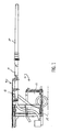
- FIG. 1 is a side view of a concrete pumping system utilizing a boom hose constructed according to the present invention
- FIG. 2 is a side view of a prior art boom hose
- FIG. 3 is a side view of a boom hose constructed according to the present invention.
- FIG. 4 is a cross-sectional view of the outer end of the boom hose.
- FIG. 5 is a cross-sectional view of the inner end of the boom hose.
- a concrete pumping system 10 includes a concrete pump 12 mounted on a truck chassis 14 .
- Concrete is delivered to a remote site via a concrete boom 16 comprised of a series of interconnected concrete pipes 18 terminating in a flexible boom hose 20 .
- a prior art boom hose would have a uniform diameter throughout its length.
- boom hose 20 has a length of approximately twelve feet.
- the above referenced inner diameters and hose lengths can be varied according to the requirements of the job as long as the inner diameter 32 of hose tip 28 is smaller than the inner diameter 30 of the hose at its connection point 24 .
Abstract
Description
Claims (5)
Priority Applications (4)
| Application Number | Priority Date | Filing Date | Title |
|---|---|---|---|
| US10/271,958 US6913041B2 (en) | 2002-10-15 | 2002-10-15 | Tapered boom hose |
| DE60320914T DE60320914D1 (en) | 2002-10-15 | 2003-01-08 | Tapered Concrete Delivery Hose |
| EP20030250112 EP1411184B1 (en) | 2002-10-15 | 2003-01-08 | Tapered boom hose |
| CA 2416217 CA2416217C (en) | 2002-10-15 | 2003-01-13 | Tapered boom hose |
Applications Claiming Priority (1)
| Application Number | Priority Date | Filing Date | Title |
|---|---|---|---|
| US10/271,958 US6913041B2 (en) | 2002-10-15 | 2002-10-15 | Tapered boom hose |
Publications (2)
| Publication Number | Publication Date |
|---|---|
| US20040069356A1 US20040069356A1 (en) | 2004-04-15 |
| US6913041B2 true US6913041B2 (en) | 2005-07-05 |
Family
ID=32042926
Family Applications (1)
| Application Number | Title | Priority Date | Filing Date |
|---|---|---|---|
| US10/271,958 Expired - Lifetime US6913041B2 (en) | 2002-10-15 | 2002-10-15 | Tapered boom hose |
Country Status (4)
| Country | Link |
|---|---|
| US (1) | US6913041B2 (en) |
| EP (1) | EP1411184B1 (en) |
| CA (1) | CA2416217C (en) |
| DE (1) | DE60320914D1 (en) |
Cited By (5)
| Publication number | Priority date | Publication date | Assignee | Title |
|---|---|---|---|---|
| US20060253062A1 (en) * | 2005-04-26 | 2006-11-09 | Alcon, Inc. | Low resistance irrigation system and apparatus |
| US20080125699A1 (en) * | 2006-11-02 | 2008-05-29 | Alcon, Inc. | Irrigation/aspiration system |
| US20100057092A1 (en) * | 2008-09-04 | 2010-03-04 | Peterson Robert H | Varying Material Properties of a Single Fluidic Line in Ophthalmology Tubing |
| US8631831B2 (en) | 2008-09-04 | 2014-01-21 | Alcon Research, Ltd. | Multi-compliant tubing |
| US10302241B2 (en) | 2014-10-30 | 2019-05-28 | Somero Enterprises, Inc. | Protective shield for concrete hose joints |
Families Citing this family (1)
| Publication number | Priority date | Publication date | Assignee | Title |
|---|---|---|---|---|
| USD916143S1 (en) | 2018-02-19 | 2021-04-13 | Federal Signal Corporation | Boom hose apparatus |
Citations (8)
| Publication number | Priority date | Publication date | Assignee | Title |
|---|---|---|---|---|
| US3651832A (en) * | 1970-09-24 | 1972-03-28 | Emco Wheaton | Articulated counterbalanced piping apparatus |
| GB1412115A (en) | 1971-12-22 | 1975-10-29 | Bernold J | Method of and apparatus for wet spraying of concrete |
| DE3224755A1 (en) | 1982-07-02 | 1984-01-05 | Johannes 4790 Paderborn Schniedermeier | Outlet nozzle for self-propelled concrete pumps |
| US4954055A (en) * | 1989-06-22 | 1990-09-04 | Baxter International, Inc. | Variable roller pump tubing |
| DE29507683U1 (en) | 1995-05-10 | 1995-07-27 | Putzmeister Maschf | Pressure conveyor |
| JPH1016075A (en) * | 1996-07-05 | 1998-01-20 | Toyo Tire & Rubber Co Ltd | Wear-resistant rubber hose with tapered part on inner peripheral face and its production |
| US5988700A (en) * | 1995-12-13 | 1999-11-23 | Sherwood Services A G | Leak proof tube connection site |
| US6142180A (en) * | 2000-04-12 | 2000-11-07 | Woodling; Roger M. | Crane-mounted concrete pump apparatus |
-
2002
- 2002-10-15 US US10/271,958 patent/US6913041B2/en not_active Expired - Lifetime
-
2003
- 2003-01-08 EP EP20030250112 patent/EP1411184B1/en not_active Expired - Lifetime
- 2003-01-08 DE DE60320914T patent/DE60320914D1/en not_active Expired - Lifetime
- 2003-01-13 CA CA 2416217 patent/CA2416217C/en not_active Expired - Lifetime
Patent Citations (8)
| Publication number | Priority date | Publication date | Assignee | Title |
|---|---|---|---|---|
| US3651832A (en) * | 1970-09-24 | 1972-03-28 | Emco Wheaton | Articulated counterbalanced piping apparatus |
| GB1412115A (en) | 1971-12-22 | 1975-10-29 | Bernold J | Method of and apparatus for wet spraying of concrete |
| DE3224755A1 (en) | 1982-07-02 | 1984-01-05 | Johannes 4790 Paderborn Schniedermeier | Outlet nozzle for self-propelled concrete pumps |
| US4954055A (en) * | 1989-06-22 | 1990-09-04 | Baxter International, Inc. | Variable roller pump tubing |
| DE29507683U1 (en) | 1995-05-10 | 1995-07-27 | Putzmeister Maschf | Pressure conveyor |
| US5988700A (en) * | 1995-12-13 | 1999-11-23 | Sherwood Services A G | Leak proof tube connection site |
| JPH1016075A (en) * | 1996-07-05 | 1998-01-20 | Toyo Tire & Rubber Co Ltd | Wear-resistant rubber hose with tapered part on inner peripheral face and its production |
| US6142180A (en) * | 2000-04-12 | 2000-11-07 | Woodling; Roger M. | Crane-mounted concrete pump apparatus |
Cited By (10)
| Publication number | Priority date | Publication date | Assignee | Title |
|---|---|---|---|---|
| US20060253062A1 (en) * | 2005-04-26 | 2006-11-09 | Alcon, Inc. | Low resistance irrigation system and apparatus |
| US20080125699A1 (en) * | 2006-11-02 | 2008-05-29 | Alcon, Inc. | Irrigation/aspiration system |
| US7981074B2 (en) | 2006-11-02 | 2011-07-19 | Novartis Ag | Irrigation/aspiration system |
| US20100057092A1 (en) * | 2008-09-04 | 2010-03-04 | Peterson Robert H | Varying Material Properties of a Single Fluidic Line in Ophthalmology Tubing |
| US8631831B2 (en) | 2008-09-04 | 2014-01-21 | Alcon Research, Ltd. | Multi-compliant tubing |
| US9149387B2 (en) | 2008-09-04 | 2015-10-06 | Novartis Ag | Varying material properties of a single fluidic line in ophthalmology tubing |
| US10302241B2 (en) | 2014-10-30 | 2019-05-28 | Somero Enterprises, Inc. | Protective shield for concrete hose joints |
| US10550990B2 (en) | 2014-10-30 | 2020-02-04 | Somero Enterprises, Inc. | Protective shield for concrete hose joints |
| USD919774S1 (en) | 2014-10-30 | 2021-05-18 | Somero Enterprises, Inc. | Protective shield for concrete hose joints |
| USD933173S1 (en) | 2014-10-30 | 2021-10-12 | Somero Enterprises, Inc. | Protective shield for covering concrete hose joints |
Also Published As
| Publication number | Publication date |
|---|---|
| US20040069356A1 (en) | 2004-04-15 |
| EP1411184A1 (en) | 2004-04-21 |
| CA2416217C (en) | 2008-10-14 |
| DE60320914D1 (en) | 2008-06-26 |
| EP1411184B1 (en) | 2008-05-14 |
| CA2416217A1 (en) | 2004-04-15 |
Similar Documents
| Publication | Publication Date | Title |
|---|---|---|
| CA2589490C (en) | End hose for discharge of thick substances | |
| US6913041B2 (en) | Tapered boom hose | |
| EP1357240A1 (en) | Method and apparatus for a line concrete pumping system | |
| JPH06158862A (en) | Concrete distribution device | |
| CN211691499U (en) | Flow guide pipe for pumping jacking steel pipe arch self-compacting concrete | |
| CN206720729U (en) | Water reducer finished product goes out material conveying device | |
| US6533500B1 (en) | Method for reducing frictional losses in tunnels | |
| CN106150097B (en) | Novel structure column concrete pumping system | |
| CN218205772U (en) | Multifunctional concrete pump truck | |
| JP3126341U (en) | Tapered hose for ready-mixed concrete pumping | |
| CN216198740U (en) | Bent pipe, material distribution arm support, pumping system and pumping machine | |
| CN2433234Y (en) | Abrasion-resistant ring for concrete transport | |
| CN111039213A (en) | Protection device for pipeline inspection | |
| CN210824468U (en) | Vibration air assisting device of powder conveying system | |
| CN211289039U (en) | Spiral corrugated pipe | |
| EP2243554A3 (en) | Multi-lumen rope for continuous flow centrifuge | |
| JP5919101B2 (en) | Raw material hose | |
| JPS58123995A (en) | Structure of oil well pipe | |
| CN217107033U (en) | High-efficiency concrete wet spraying machine | |
| CN206076897U (en) | A kind of high-strength polyvinyl chloride pipe | |
| CN210153533U (en) | Overhead water delivery device | |
| CN216382931U (en) | Conveying pipe connecting mechanism for special concrete production | |
| AU714337B3 (en) | Fluid flow pump | |
| JP3642954B2 (en) | Reducer for refractory spraying | |
| CN205806725U (en) | A kind of corrugated thin-wall stainless steel tube |
Legal Events
| Date | Code | Title | Description |
|---|---|---|---|
| AS | Assignment |
Owner name: CONSTRUCTION FORMS, INC., WISCONSIN Free format text: ASSIGNMENT OF ASSIGNORS INTEREST;ASSIGNORS:LEHNHARDT, GARY D.;ALTAMIRANO, ROLANDO;REEL/FRAME:013591/0496;SIGNING DATES FROM 20020927 TO 20021007 |
|
| STCF | Information on status: patent grant |
Free format text: PATENTED CASE |
|
| FPAY | Fee payment |
Year of fee payment: 4 |
|
| FPAY | Fee payment |
Year of fee payment: 8 |
|
| SULP | Surcharge for late payment |
Year of fee payment: 7 |
|
| FPAY | Fee payment |
Year of fee payment: 12 |
|
| AS | Assignment |
Owner name: GLAS AMERICAS LLC, NEW JERSEY Free format text: SECURITY INTEREST;ASSIGNOR:CONSTRUCTION FORMS, INC.;REEL/FRAME:064281/0432 Effective date: 20230714 |