US6922415B1 - Apparatus and method for a non-symmetrical half-duplex DSL modem - Google Patents
Apparatus and method for a non-symmetrical half-duplex DSL modem Download PDFInfo
- Publication number
- US6922415B1 US6922415B1 US09/537,609 US53760900A US6922415B1 US 6922415 B1 US6922415 B1 US 6922415B1 US 53760900 A US53760900 A US 53760900A US 6922415 B1 US6922415 B1 US 6922415B1
- Authority
- US
- United States
- Prior art keywords
- dtu
- variable length
- length frame
- response
- communicating
- Prior art date
- Legal status (The legal status is an assumption and is not a legal conclusion. Google has not performed a legal analysis and makes no representation as to the accuracy of the status listed.)
- Expired - Fee Related
Links
Images


Classifications
-
- H—ELECTRICITY
- H04—ELECTRIC COMMUNICATION TECHNIQUE
- H04L—TRANSMISSION OF DIGITAL INFORMATION, e.g. TELEGRAPHIC COMMUNICATION
- H04L12/00—Data switching networks
- H04L12/28—Data switching networks characterised by path configuration, e.g. LAN [Local Area Networks] or WAN [Wide Area Networks]
- H04L12/2854—Wide area networks, e.g. public data networks
- H04L12/2856—Access arrangements, e.g. Internet access
- H04L12/2858—Access network architectures
- H04L12/2859—Point-to-point connection between the data network and the subscribers
-
- H—ELECTRICITY
- H04—ELECTRIC COMMUNICATION TECHNIQUE
- H04L—TRANSMISSION OF DIGITAL INFORMATION, e.g. TELEGRAPHIC COMMUNICATION
- H04L12/00—Data switching networks
- H04L12/28—Data switching networks characterised by path configuration, e.g. LAN [Local Area Networks] or WAN [Wide Area Networks]
- H04L12/2854—Wide area networks, e.g. public data networks
- H04L12/2856—Access arrangements, e.g. Internet access
- H04L12/2869—Operational details of access network equipments
- H04L12/287—Remote access server, e.g. BRAS
- H04L12/2876—Handling of subscriber policies
-
- H—ELECTRICITY
- H04—ELECTRIC COMMUNICATION TECHNIQUE
- H04L—TRANSMISSION OF DIGITAL INFORMATION, e.g. TELEGRAPHIC COMMUNICATION
- H04L5/00—Arrangements affording multiple use of the transmission path
- H04L5/14—Two-way operation using the same type of signal, i.e. duplex
-
- H—ELECTRICITY
- H04—ELECTRIC COMMUNICATION TECHNIQUE
- H04M—TELEPHONIC COMMUNICATION
- H04M11/00—Telephonic communication systems specially adapted for combination with other electrical systems
- H04M11/002—Telephonic communication systems specially adapted for combination with other electrical systems with telemetering systems
-
- H—ELECTRICITY
- H04—ELECTRIC COMMUNICATION TECHNIQUE
- H04M—TELEPHONIC COMMUNICATION
- H04M11/00—Telephonic communication systems specially adapted for combination with other electrical systems
- H04M11/04—Telephonic communication systems specially adapted for combination with other electrical systems with alarm systems, e.g. fire, police or burglar alarm systems
-
- H—ELECTRICITY
- H04—ELECTRIC COMMUNICATION TECHNIQUE
- H04M—TELEPHONIC COMMUNICATION
- H04M11/00—Telephonic communication systems specially adapted for combination with other electrical systems
- H04M11/06—Simultaneous speech and data transmission, e.g. telegraphic transmission over the same conductors
- H04M11/062—Simultaneous speech and data transmission, e.g. telegraphic transmission over the same conductors using different frequency bands for speech and other data
-
- H—ELECTRICITY
- H04—ELECTRIC COMMUNICATION TECHNIQUE
- H04M—TELEPHONIC COMMUNICATION
- H04M7/00—Arrangements for interconnection between switching centres
- H04M7/006—Networks other than PSTN/ISDN providing telephone service, e.g. Voice over Internet Protocol (VoIP), including next generation networks with a packet-switched transport layer
Definitions
- the present invention generally relates to an apparatus and method that enables one or more modems, connected at a premises to a single subscriber line, to simultaneously communicate data with a modem at the central office end of the subscriber line, using non-symmetrical half-duplex data transmissions.
- Non-symmetrical half-duplex data transmissions include half-duplex transmission on a subscriber line wherein the transmission time in one direction is different than the other direction and/or the transmission data rate in one direction is different than the other direction.
- DSL digital subscriber line
- DSL technologies are ADSL, RADSL, HDSL, VDSL, basic rate ISDN, etc.
- FDM frequency division multiplex
- ECD echo canceling duplex
- TDD time division duplexing
- FDM the physical layer transmissions in each direction of communication utilize separate frequency bands with a guard band between these two communication bands.
- a result is that FDM requires more than twice the channel bandwidth than that required for just one communication direction.
- An additional consequence of FDM is that FDM suffers increased channel loss and reduced performance in one direction.
- ECD the physical layer transmissions in both directions of communication utilize echo canceling in the same frequency band used to separate transmit and receive signals.
- a result is that ECD is susceptible to non-linear distortion and other non-cancelable aspects of the transmitted signal with a consequence that ECD suffers decreased dynamic range and reduced performance in both directions of communication.
- TDD the physical layer transmissions alternate in one direction, then the other direction, in pre-arranged, equal time periods.
- both directions of communication utilize the same frequency band and do not require echo canceling, thus avoiding the above disadvantages of FDM and ECD.
- TDD suffers the disadvantage of the maximum data rate in each direction of transmission is one-half that achievable in only one direction.
- FDM, ECD and TDD the physical layer transmissions are decoupled from and independent of the higher communication layers.
- a full duplex variation restricted to communicating Ethernet data and called “EtherLoop” (developed by Elastic Networks) uses FDM, but couples transmissions to only Ethernet messages.
- DSL communication in the prior art is point-to-point, in that there is a single operating DSL modem at each end of the subscriber line with no provision for multiple DSL modems to be able to operate at either end.
- Some leased line voiceband modems in the prior art provide for a single central site modem which communicates with one or more remote modems: a concept referred to as “four-wire multipoint communications.”
- An example of such a modem is one that complies with the industry standard ITU V.27bis.
- the communication channel to each remote modem is a four-wire connection and the modems are typically widely geographically dispersed over the public telephone network.
- the central site modem transmission is controlled by an attached central site computer or data terminal, which uses non-data control signals.
- non-data control signals are those prescribed in industry standard ITU V.24 CT105 to control the start and end of transmissions.
- dial line voiceband modems in the prior art provide for a single central site modem which communicates with one or multiple remote modems, which is a concept referred to as “two-wire PSTN communications.”
- the communication channel to each remote modem is a two-wire PSTN connection and the modems are typically, widely geographically dispersed over the public telephone network.
- the physical layer is half-duplex, and the data protocol is half duplex.
- the direction of transmission is determined external from the dial modem and modem transmissions are thus controlled externally by control signals, such as Request-to-Send or V.24 CT105.
- Another example is for remote transmission controlled by an attached remote computer or data terminal which also uses non-data control signals such as those described in industry standard ITU V.24 CT105 to control the start and end of transmissions.
- ITU V.24 CT105 non-data control signals
- the central site transmission is continuous and the remote transmission is controlled as in the dial line case.
- the attached computers or data terminals must ensure that transmissions do not overlap by monitoring the ends of received signals, for example via ITU V.24 CT109, and delaying CT105 accordingly.
- Ethernet local area network communication wherein the physical channel can be a short two-wire channel, never a general subscriber line.
- transmissions are derived directly from the upper layer data protocol, but there is no central control, and therefore, the signals may collide.
- a special upper layer protocol must manage the detrimental effects of collisions. It may also be constructive to note that the Ethernet techniques cannot be efficiently applied to subscriber loops because of collisions and the ability to span the distances incurred on a loop.
- Point-to-Point Protocol defined in Internet Engineering Task Force (IETF) specification Request for Comment (RFC) 1661 is defined to operate as follows: “The Point-to-Point Protocol is designed for simple links which transport packets between two peers. These links provide full-duplex simultaneous bi-directional operation.” Up to this time, the Point-to-Point Protocol has not been used in connection with half-duplex links.
- modems have lacked the ability to conduct half-duplex transmission on a subscriber line wherein the transmission time in one direction is different than the other direction and/or the transmission data rate in one direction is different than the other direction.
- the present invention provides an apparatus and method for providing non-symmetrical half-duplex data communications.
- the apparatus can be implemented as follows.
- the non-symmetrical half-duplex data communications apparatus includes interface circuitry connectable to a communications link and modulation circuitry that provides the ability to transmit and receive non-symmetrical half-duplex signals over the communications link.
- the modulation circuitry provides the ability to transmit signals with a transmission time and/or transmission data rate, that is different than the transmission time and/or transmission data rate of receive signals.
- the present invention can also be viewed as providing a method for providing non-symmetrical half-duplex data communication.
- the method can be broadly summarized by the following steps: (1) providing a communications link for transmitting and receiving half-duplex signals; and (2) transmitting a half-duplex signal over said communications link with a transmission time and/or transmission data rate, that is different than the transmission time and/or transmission data rate of receive signals.
- FIG. 1 is a view of the central office (CO) wire centers and user premises layout of the prior art.
- FIG. 2 is a block diagram of the connections between the central office wire center and residence data terminal unit at the user premises as shown in FIG. 1 .
- FIG. 3 is a view of the CO wire centers and user premises layout of the present invention.
- FIG. 4 is a block diagram of the connections between the central office wire center and residence data terminal units at the user premises as shown in FIG. 3 .
- FIG. 5 is a block diagram of the OSI layers of the present invention.
- FIG. 6A is a block diagram of an example of the transmission convergence and physical media dependent functions of the data terminal unit at the central office.
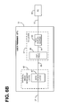
- FIG. 6B is a block diagram of the transmission convergence and physical media dependent layers of the residence data terminal unit of the present invention.
- FIG. 7A is a block diagram of the multipoint-capable DSL poll or response frame with data.
- FIG. 7B is a block diagram of the multipoint DSL poll or response frame without data.
- FIGS. 8A to 8 D are schematic diagrams showing the modes of poll and response transmissions that are placed on the local loop by the DSP logic in FIGS. 6A and 6B , and that the transmission time on the local loop in one direction can be vastly different than the transmission time in the opposite direction; more particularly:
- FIG. 9 is a graph showing the frequency spectrum of the data terminal unit and the POTS channel, as shown in FIG. 3 , when any POTS device is “off-hook.”
- FIG. 10 is a graph showing the frequency spectrum of the data terminal unit and the POTS channel, as shown in FIG. 3 , when all POTS devices are “on-hook.”
- FIG. 11A is a block diagram of an example that represents a “downstream intensive” application for the data terminal units shown in FIGS. 6A and 6B , where all the transmission time is dedicated to downstream transmission, with the exception of necessary upstream error information as dictated by the link layer communication protocol.
- FIG. 11B is a block diagram of an example that represents an “upstream intensive” application for the data terminal units shown in FIGS. 6A and 6B , where all transmission time is dedicated to upstream transmission, with the exception of necessary downstream error information as dictated by the link layer communication protocol.
- FIG. 11C is a block diagram of an example that represents a “symmetrical” application for the data terminal units shown in FIGS. 6A and 6B , where the transmission time is dedicated equally to downstream and upstream transmission, and where the error information is included in the upstream and downstream transmissions as dictated by the link layer communication protocol.
- FIG. 11D is a block diagram of an example that represents changing point-to-point application for the data terminal units shown in FIGS. 6A and 6B , where the application is initially “upstream intensive” and changes to “downstream intensive.”
- DTU-R refers to data terminal unit-residence which is a DSL transceiver or modem located typically at a residence or small business.
- DTU-C refers to data terminal unit-central office, which is a DSL transceiver or modem located typically at a telephone central office, at a telephone digital loop carrier site, or at a functionally similar location on a campus.
- the present invention is generally directed to a non-symmetrical half-duplex data communications apparatus and method that are implemented via logic to perform selected program routine sequences. These sequences include the transmission of packets or cells from one or multiple DSL modems directly connected, at a premises, to a single subscriber line to simultaneously provide data sessions with a single DSL modem at the other end of the subscriber line.
- the non-symmetrical half-duplex data communications apparatus and method of the present invention creates the appearance to the data terminal unit at the user residence that full duplex communication is being achieved.
- the appearance of full duplex communication is achieved so that the data rate and performance in each direction can equal the full data rate capacity and full performance potential of the subscriber line itself at moments when no other user data communication is in progress.
- the present invention creates the appearance that the full data rate capacity of the subscriber line is shared.
- the non-symmetrical half-duplex data communications apparatus and method of the present invention achieves the above desirable attributes without requiring the excessively high channel bandwidth utilization of FDM or the reduced performance of ECD.
- the non-symmetrical half-duplex data communications apparatus and method also can achieve twice the data rate in each direction of transmission than that of TDD.
- the non-symmetrical half-duplex data communications apparatus and method furthermore achieves these attributes without control by an external computer or data terminal.
- the non-symmetrical half-duplex data communications apparatus and method achieves twice the data rate in each direction of transmission than that of TDD by using Adaptive Time Domain Duplexing (ATDD).
- ATDD is an improvement upon TDD, where the 50% duty cycle of TDD is replaced by a duty cycle that adaptively and near-instantaneously is varied from near 0% to near 100% based on protocol responsive to the user data communication needs in each direction of transmission.
- FIG. 1 illustrates the plain old telephone system (POTS) network with DTU-Cs 16 and DTU-Rs 45 of the prior art.
- the POTS network includes user premises 41 connected to a central office wire center 11 via a subscriber line 27 .
- Each subscriber line 27 is connected to the user premises 41 , which further connects to a user premises line 47 , for distribution of POTS service and DSL service throughout the user premises.
- POTS devices connected to each user premises line 47 , such as telephones 44 , facsimile (fax) machines 42 , and the like.
- Prior art baseband DSLs typically cannot operate with POTS devices, in which case all of the POTS entities of FIG. 1 are absent.
- POTS splitters can be utilized at the premises, when required, to separate the POTS lower frequency band, which is between about 0 kHz and about 4 kHz, from the DSL signals, which are at a higher frequency level than the POTS frequency band.
- the splitter would be on the incoming subscriber line 27 , with the DTU-R 45 coming off one splitter line and the two phones 44 and fax 42 off the other.
- each user premises is connected via a subscriber line 27 to a central office wire center 11 .
- the subscriber line 27 is connected to a POTS splitter device that separates the analog POTS signals from data signals.
- the POTS signals are sent to a POTS switch 14 that is connected to the other central office wire centers, via the public switched telephone network (PSTN) 28 over connection 26 .
- DTU data signals are separated from the POTS analog signals at POTS splitter 15 and are connected to DTU-Cs 16 within the central office wire center 11 .
- DTU-Cs 16 are further connected to digital data networks such as the Internet 29 through a remote access server (RAS) 17 .
- RAS remote access server
- the user When a user desires to place a telephone call on device 44 , the user picks up the telephone and puts the subscriber line 27 in an off-hook condition that is detected at the central office wire center 11 by closed switch hooks (not shown).
- the off-hook condition signals the central office wire center 11 , via subscriber line 27 , to accept an outgoing call by allowing a flow of D.C. current and a dial tone of 480 Hz to be sent to device 44 .
- the outgoing telephone call signals are transmitted, as described before, via subscriber line 27 to POTS splitter 15 .
- the analog POTS system signals are separated from the DSL modem signals, and the POTS signals are directed towards the POTS switch 14 for transmission, via the PSTN network 28 , to another telephone (not shown).
- DTU-R 45 A description of digital signals transmitted to/from the user premises will now be provided.
- the digital signals from the digital device are transformed into full duplex analog signals, via modulation by DTU-R 45 .
- the signals are transmitted over the user premises line 47 to the subscriber line 27 for final delivery to the local central office wire center 11 .
- the digitally modulated analog signals going into POTS splitter 15 are separated from the analog POTS signals, and are directed to DTU-Cs 16 .
- DTU-Cs 16 demodulate the analog signals back to their original digital data signals.
- DTU-Cs 16 transmit the digital data over the Internet 29 via the RAS 17 .
- the digital data signals sent over the Internet 29 are typically received by an internet server 47 , which returns information to the user.
- FIG. 2 illustrates the CO wire center DTU-C and DTU-R connections used in the prior art which include multiple subscriber lines 27 . These multiple subscriber lines 27 are connected to a user premises to enable multiple full duplex DTU-Rs 45 to simultaneously communicate data with the central office 11 .
- FIG. 2 Also illustrated in FIG. 2 is the type of communication traffic occurring.
- communication between remote access server (RAS) 17 and each individual DTU-C 16 occurs with multiple full duplex Point to Point Protocol (PPP) sessions over interface lines 31 .
- PPP Point to Point Protocol
- the input and output from each DTU-C 16 on subscriber lines 27 to and from each DTU-R 45 occurs using multiple full duplex PPP sessions.
- communication between DTU-Rs 45 and digital type devices, such as a PC 46 occur utilizing multiple full duplex PPP sessions over interface lines 32 .
- FIG. 3 illustrates the CO wire centers and user premises layout in accordance with the present invention, which enables one or more DTU-Rs 51 , connected at a premises 41 to a single subscriber line 27 , to simultaneously communicate data with a single DTU-C 18 at the central office 11 end of the subscriber line 27 .
- DTU-C data is sent to a single DTU-R at one premises, but the present invention also applies to a DTU-R that can support one or more users at a single premises and one or more users at one or more premises.
- FIG. 4 illustrates one example of the CO wire center connections to the DTU-R. These connections can enable one or more DTU-Rs 51 to be connected to one or more personal computers (PC) 46 and/or other digital type devices located at premises 41 . These multiple connections can be connected to a single subscriber line 27 , to simultaneously communicate data with a single DTU-C 18 at the central office 11 end of the subscriber line 27 .
- PC personal computers
- the communication between RAS 17 and the single DTU-C 18 occurs utilizing one or more full duplex PPP sessions over interface lines 31 .
- Communication between the single DTU-C 18 and the one or more DTU-Rs 51 at the user premises across the single subscriber line 27 occurs utilizing one or more half duplex PPP sessions.
- These half-duplex sessions utilize point-to-point full duplex data protocols, for example, but not limited to, the Point to Point Protocol (PPP) defined in Internet Engineering Task Force (IETF) specification Request for Comment (RFC) 1661.
- PPP Point to Point Protocol
- IETF Internet Engineering Task Force
- RRC Request for Comment
- the OSI 7-layer model Illustrated in FIG. 5 is the OSI 7-layer model, including information relating to the physical and data link layers in accordance with the present invention.
- the Physical Layer 61 contains two distinct sub-layers, the Transmission Convergence (TC) Sublayer 67 and the Physical Media Dependent (PMD) Sublayer 66 .
- the PMD 66 deals with the aspects that are dependent on the transmission medium selected, i.e., the subscriber line.
- the PMD 66 specifies the physical medium and the transmission characteristics (e.g., bit timing, line coding). However, PMD 66 does not include framing or overhead information.
- the TC layer 67 deals with the physical layer aspects, which are independent of the transmission medium characteristics. Most of the functions comprising the TC layer 67 are involved with the generation and processing of some overhead information contained within the frame.
- the Data Link Layer 62 uses Point to Point Protocol (PPP) 68 .
- PPP Point to Point Protocol
- the invention described herein specifies techniques that enable PPP to operate half-duplex over the subscriber line 27 .
- One DTU-C 18 can service one or more DTU-Rs 51 , with each DTU-R 51 appearing to receive a unique PPP session.
- An alternative embodiment utilizes asynchronous transfer mode (ATM) cells as a link layer protocol.
- ATM asynchronous transfer mode
- FIG. 6A is a block diagram of an example of a CO wire center multichannel data communications device DTU-C 18 constructed in accordance with the present invention.
- the typical configuration of the multichannel data communication device DTU-C 18 at the central office wire center 11 has the multichannel data communication device DTU-C 18 connected, via a POTS splitter 15 (FIG. 3 ), to the subscriber lines 27 .
- a POTS splitter 15 FIG. 3
- one or more full duplex PPP sessions are transported over interface lines 31 to the Full Duplex Buffers 75 .
- the full duplex buffers 75 include circuitry to convert serial data streams into parallel data. Each full duplex PPP session is carried over a separate interface line 31 .
- the control processor/digital multiplexer 74 Upon detection of a PPP frame in any of the full duplex buffers 75 , the control processor/digital multiplexer 74 will encapsulate this PPP frame, as described below with respect to FIGS. 7A and 7B , and send it to the modulator/demodulator 71 via line 78 .
- the modulator/demodulator 71 will modulate and transmit this frame onto the subscriber line 27 to far end subscriber DTU-R 51 .
- An alternative embodiment has the data communication device DTU-C 18 connected, via a POTS splitter 15 (FIG. 3 ), to a single subscriber line 27 .
- one full duplex PPP session is conducted over interface line 31 to the Full Duplex Buffer 75 .
- the control processor/digital multiplexer 74 Upon detection of a multipoint DSL frame (i.e. a PPP frame) in the full duplex buffer 75 , the control processor/digital multiplexer 74 will encapsulate this multipoint DSL frame (i.e. a PPP frame), and send it to the modulator/demodulator 71 via line 78 .
- These multipoint DSL frames i.e. a PPP frames
- the modulator/demodulator 71 will modulate and transmit this frame onto the subscriber line 27 to a single far end subscriber DTU-R 51 .
- FIG. 6B is a block diagram of the DTU-R 51 constructed in accordance with the present invention.
- DTU-R 51 will demodulate the signal transmitted by DTU-C 18 over subscriber line 27 using modulator/demodulator logic 81 .
- the demodulated data is sent to control processor 84 via line 88 .
- Control processor 84 will check for errors by analyzing the FCS octets 95 (FIGS. 7 A and 7 B). If no errors exist, then control processor 84 will determine if this poll is meant for it by utilizing the address header 93 ( FIGS. 7A and 7B ) in the multipoint DSL frame 91 or 96 (FIGS. 7 A and 7 B). These multipoint DSL frames 91 and 96 , are described below with respect to FIG.
- the control processor 84 will check for a PPP frame 92 (FIG. 7 A). If this PPP frame 92 ( FIG. 7A ) exists, this PPP frame 92 will be placed into full duplex buffer 85 via line 86 . The full duplex buffer 85 will transfer this PPP frame 92 ( FIG. 7A ) to PC 46 via line 32 .
- the PC 46 can at any time transfer a PPP frame 92 ( FIG. 7A ) into full duplex buffer 85 via line 32 .
- DTU-R 51 After receiving a poll on subscriber line 27 , DTU-R 51 knows that it is its turn to communicate information. If a PPP frame 92 ( FIG. 7A ) exists in the full duplex buffer 85 , the PPP frame 92 is encapsulated into a multipoint DSL frame 91 ( FIG. 7A ) by control processor 84 , and sent to modulator/demodulator 81 for modulation onto the subscriber line 27 .
- control processor 84 will send a signal indicative of no data multipoint DSL frame 96 to modulator/demodulator logic (modem) 81 .
- Modulator/demodulator logic 81 will transfer this response to subscriber line 27 .
- FIG. 7A illustrates the method of the present invention that the DTU-C 18 uses to address the various DTU-Rs 51 .
- the control processor/digital mutiplexer 74 ( FIG. 6A ) creates a multipoint DSL frame 91 by using TC layer circuitry 66 ( FIG. 6A ) to encapsulate the PPP frame 92 .
- This TC layer circuitry 66 includes control processor/digital mutiplexer 74 circuitry that generates an address header 93 and a frame check sequence (FCS) 95 .
- the control processor/digital mutiplexer 74 looks to the source line 31 and determines the appropriate address header 93 for the destination device.
- the address header 93 includes information that indicates to one of the plurality of endpoints that multipoint DSL frame 91 is meant for it.
- the FCS 95 octets assure that the entire multipoint DSL frame 91 is correct.
- FIG. 7B shows the case where either the DTU-C 18 ( FIG. 6A ) or remote DTU-R 51 ( FIG. 6B ) has no data to send.
- the address header 93 and FCS 95 octets are still included, but no PPP information is sent.
- No data multipoint DSL frame 96 is used for cases where the subscriber DSL modem 51 has no PPP data to send in a response. It can also be used by DTU-C 18 to poll a subscriber DTU-R 51 for PPP information, even though DTU-C 18 has no PPP frames to send.
- FIGS. 8A through 8D Illustrated in FIGS. 8A through 8D are schematic diagrams demonstrating the polling algorithms that allow modulator/demodulator logic 71 and 81 to simultaneously support one or more premises.
- two DTUs exist on the line 27 , namely, the DTU-C 18 and the user premises DTU-R 51 .
- poll/response modulation can allow one or more user premises DTU-Rs 51 to exist on the same local loop.
- ATDD adaptive time division duplexing
- DTU-C 18 controls which of the premises multiple DTU-Rs 51 on the subscriber line 27 is allowed to transmit.
- a “poll” is a transmission from the DTUC 18
- a “response” is a transmission from a user premises DTU-R 51 .
- a poll will usually occur followed normally by a response.
- silentence is a legitimate response.
- DTU-C 18 will recognize this as a response with no data.
- the start of a poll or a response is indicated by the PMD layer 66 ( FIG. 5 ) turning on the carrier.
- the end of a poll or a response is indicated by the PMD layer 66 ( FIG. 5 ) turning off the carrier.
- the multipoint DSL frames 91 and 96 do not need flag delimiters, as are normally found in PPP frames. Instead, the turning on and off of the carrier indicates the start and the stop, respectively, of a PPP frame.
- the method used to accomplish the PMD layer is described in commonly assigned U.S. Pat. No. 4,669,090, issued May 26, 1987, entitled “Half-Duplex Modem Without Turnaround Delay,” herein incorporated by reference, and in commonly assigned U.S. Pat. No. 4,744,092, issued May 10, 1988, entitled “Transparent Error Detection In Half Duplex Modems,” herein incorporated by reference.
- FIGS. 8A through 8D are schematic diagrams demonstrating the four respective modes for the poll/response cycle.
- FIG. 8A Illustrated in FIG. 8A demonstrates a poll with no user data step 111 .
- the poll with no user data step 111 is followed by a response with no user data step 112 .
- FIG. 8B Illustrated in FIG. 8B demonstrates a poll with user data at step 113 .
- the poll with user data step 113 is followed by a response with no user data at step 114 .
- FIG. 8C Illustrated in FIG. 8C demonstrates a poll with no user data at step 115 .
- the poll with no user data step 115 is followed by a response with user data at step 116 .
- FIG. 8D Illustrated in FIG. 8D demonstrates a poll with user data at step 117 .
- the poll with user data step 117 is followed by a response with user data at step 118 .
- FIGS. 8A-8D the transmission time in one direction can be vastly different than the transmission time in the opposite direction. Specifically, as seen in FIG. 8B , the transmission time of the poll drop n-with data 113 is greater in time than the response drop n-no data 114 . This is also illustrated in FIGS. 8C and 8D where the poll drop n 115 and 117 , respectively, is different-in size than the response drop n- 116 and 118 , respectively. This illustrates the non-symmetrical half duplex capability of the present invention.
- FIG. 9 is a diagram illustrating frequency band communications of DUT-C 18 and DUT-R 51 .
- the terminology “frequency band communications” is used here to indicate communication of information within a certain defined, frequency band.
- POTS communications are transmitted in the frequency band 121 defined between about 0 Hz (DC) and about 4 kHz.
- a second transmission frequency band 122 is defined at a higher frequency level than the POTS frequency band 121 and is used in the transmission of digital subscriber line (DSL) communications.
- a guard band 123 is used to separate the two transmission frequency bands 121 and 122 .
- the DSL transmission frequency band 122 is more broadly denominated as “xDSL,” wherein the “x” generically denominates any of a number of transmission techniques within the DSL family.
- ADSL asymmetric digital subscriber line
- RADSL rate adaptive digital subscriber line
- HDSL high-bit-rate DSL
- VDSL-very-high-bit-rate DSL etc.
- xDSL transmission frequency bands may encompass a bandwidth of greater than about 1 MHz.
- a third transmission frequency band 125 is illustrated at a higher frequency level than both the POTS frequency band 121 , and the second transmission frequency band 122 . This third transmission frequency band 125 can be used for the transmission VDSL communications without regard to any other activity in the POTS frequency band 121 or the DSL second transmission frequency band.
- an alternative embodiment of the present invention provides an upper transmission band having an upper frequency boundary that is much lower than the 1 MHz frequency boundary often encountered in xDSL transmissions.
- the upper frequency boundary of the present invention may be defined in a range that is readily supported by, or compatible with, transmission systems (and attached POTS-type equipment) presently in place between a customer premises and a central office, without the need for extraneous devices such as POTS filters and POTS splitters, as will be understood by those skilled in the art.
- a multichannel data communication device namely, DSL modem 51
- DSL modem 51 for achieving efficient data communications between a customer premises 41 and a central office 11 across a local loop 27 by dynamically allocating a transmission frequency bandwidth for transmitting data.
- the present invention may utilize dynamic allocation of the data transmission frequency band in response to POTS communications activity across the same line as described in commonly assigned and co-pending U.S. Patent Application entitled, “Digital Subscriber Loop Data Communications Method Enabling Simultaneous Data And POTS Without POTS Filters/Splitters Or Special Premises Wiring,” Ser. No. 08/962,796, filed on Nov. 3, 1997, now U.S. Pat. No. 6,061,392 herein incorporated by reference.
- the non-symmetrical half-duplex data communications apparatus and method of the present invention may utilize the transmission frequency band 124 for the data communications at times when there is no present demand for transmitting voice information. That means that the data transmission frequency band spectrum 122 ( FIG. 9 ) can extend to 0 kHz as in the data transmission frequency band 124 .
- the present invention reallocates the transmission frequency band 124 for the data communications, so that the data transmission frequency band spectrum 122 ( FIG. 9 ) causes no overlap or interference with the POTS transmission frequency band 121 (FIG. 9 ). This also ensures that there is no significant interference to POTS-type attached equipment. It is possible for other services to be on the line in higher frequency bands 125 .
- the frequency band spectrum need not change when on/off-hook. That is, FIG. 10 can look like FIG. 9 without POTS transmission frequency band 121 being utilized.
- the spectrum can be baseband or passband with specific modulation examples being CAP, QAM, PAM, 2B1Q.
- FIGS. 11A through 11D Illustrated in FIGS. 11A through 11D are examples of subscriber line communication that include several types of point-to-point applications that each benefit from different data rates and different transmission times in each direction of transmission. These same concepts can also be applied to those applications where multipoint DTU-Rs are deployed.
- FIG. 11A illustrates an example of a point-to-point application that is “downstream intensive.”
- a downstream intensive application is utilized when there is a desire to move information as quickly as possible from the DTU-C 18 to the premises DTU-R 51 .
- the downstream intensive application most if not all the transmission time is dedicated to the downstream transmission with the exception of any necessary upstream confirmation information.
- This upstream confirmation information as dictated by the link layer communication protocol.
- the downstream transmission of the DSL data 144 and 146 is interspersed with the upstream the DSL confirmation information 145 and 147 .
- FIG. 11B illustrates an example of a point-to-point application that is “upstream intensive.”
- An upstream intensive application is utilized when there is a desire to move information as quickly as possible from the premises DTU-R to the DTU-C.
- an upstream intensive application most if not all the transmission time is dedicated to the upstream transmission with the exception of the necessary downstream confirmation information.
- This downstream confirmation informnation as dictated by the link layer communication protocol.
- the upstream transmission of the DSL data 154 and 156 is interspersed with the downstream DSL confirmation information 155 and 157 .
- FIG. 11C illustrates an example of a point-to-point application that is “symmetrical” where the desire is to concurrently transfer as quickly as possible approximately equal amounts of information from the DTU-C 18 to the premises DTU-R 51 and from the premises DTU-R 51 to the DTU-C 18 .
- the upstream confirmation information is included in the upstream transmission
- downstream confirmation information is included in the downstream transmission, both as dictated by the link layer communication protocol.
- the downstream DSL data 164 and 166 is approximately equal to the upstream DSL data 165 and 167 .
- FIG. 11D illustrates an example of a variation of the above three point-to-point applications where the communication needs sequentially change in time from upstream intensive to downstream intensive as the upstream application is completed.
- the maximum upstream DSL data transmission 174 and 176 concludes, thereby allowing maximum downstream DSL data transmission 177 to occur.
- the downstream DSL data 175 includes confirmation information.
- the upstream DSL data transmission 178 includes confirmation information.
- the amount of information communicated is the product of data rate and transmission time. For example, 1 megabit of information can be communicated in 10 seconds at 100 kbps or in 100 seconds at 10 kbps.
- 1 megabit of information can be communicated in 10 seconds at 100 kbps or in 100 seconds at 10 kbps.
- the non-symmetrical half-duplex data communications apparatus and method of the present invention also may utilize the mixed capability DTU-C 18 having at least one half-duplex signal inbound, and at least one full-duplex signal outbound as described in commonly assigned and co-pending U.S. Patent Application entitled “Echo Cancellation for Multipoint Networks,” Ser. No. 08/994,867 filed on, Mar. 5, 1997, now U.S. Pat. No. 6,014,371 herein incorporated by reference.
- the non-symmetrical half-duplex data communications apparatus and method provide for automatic control of all communications on the subscriber line by the data terminal unit at the central office.
- This automatic control by the data terminal unit at the central office is accomplished in such a way, that the subscriber line data rate capacity is optimally utilized at all moments.
- This automatic control by the data terminal unit at the central office also avoids collisions between all data terminal units, and offers the selection of service priorities for data throughput between each user and the data terminal unit at the central office.
- the non-symmetrical half-duplex data communications apparatus and method provide for direct control of all data terminal unit subscriber line signals from the sensing of data transmission needs of the data protocols above the physical media dependent layer.
- the transmissions directives are thus derived from higher layer protocols without the need for non-data interfaces.
- the non-symmetrical half-duplex data communications apparatus and method provides utilization of point-to-point full duplex data protocols, for example but not limited to, the Point to Point Protocol (PPP) defined in Internet Engineering Task Force (IETF) specification Request for Comment (RFC) 1661.
- PPP Point to Point Protocol
- IETF Internet Engineering Task Force
- RRC Request for Comment
- the non-symmetrical half-duplex data communications apparatus and method provides data transmission in the multi-point environment.
Abstract
Description
-
-
FIG. 8A is a schematic diagram showing a poll with no central office user data, followed by a response with no premises user data. -
FIG. 8B is a schematic diagram showing a poll with central office user data, followed by a response with no premises user data. -
FIG. 8C is a schematic diagram showing a poll with no central office user data, followed by a response with premises user data. -
FIG. 8D is a schematic diagram showing a poll with central office user data, followed by a response with premises user data.
-
Claims (30)
Priority Applications (2)
| Application Number | Priority Date | Filing Date | Title |
|---|---|---|---|
| US09/537,609 US6922415B1 (en) | 1998-02-26 | 2000-03-29 | Apparatus and method for a non-symmetrical half-duplex DSL modem |
| US10/179,544 US20020167949A1 (en) | 1998-02-26 | 2002-06-25 | Apparatus and method for asynchronous transfer mode (ATM) adaptive time domain duplex (ATDD) communication |
Applications Claiming Priority (4)
| Application Number | Priority Date | Filing Date | Title |
|---|---|---|---|
| US3122698A | 1998-02-26 | 1998-02-26 | |
| US09/032,671 US6580785B2 (en) | 1997-02-28 | 1998-02-27 | Apparatus and method for simultaneous multiple telephone type services on a single telephone line |
| US12806499P | 1999-04-07 | 1999-04-07 | |
| US09/537,609 US6922415B1 (en) | 1998-02-26 | 2000-03-29 | Apparatus and method for a non-symmetrical half-duplex DSL modem |
Related Parent Applications (1)
| Application Number | Title | Priority Date | Filing Date |
|---|---|---|---|
| US09/032,671 Continuation-In-Part US6580785B2 (en) | 1997-02-28 | 1998-02-27 | Apparatus and method for simultaneous multiple telephone type services on a single telephone line |
Related Child Applications (1)
| Application Number | Title | Priority Date | Filing Date |
|---|---|---|---|
| US10/179,544 Continuation-In-Part US20020167949A1 (en) | 1998-02-26 | 2002-06-25 | Apparatus and method for asynchronous transfer mode (ATM) adaptive time domain duplex (ATDD) communication |
Publications (1)
| Publication Number | Publication Date |
|---|---|
| US6922415B1 true US6922415B1 (en) | 2005-07-26 |
Family
ID=34753558
Family Applications (1)
| Application Number | Title | Priority Date | Filing Date |
|---|---|---|---|
| US09/537,609 Expired - Fee Related US6922415B1 (en) | 1998-02-26 | 2000-03-29 | Apparatus and method for a non-symmetrical half-duplex DSL modem |
Country Status (1)
| Country | Link |
|---|---|
| US (1) | US6922415B1 (en) |
Cited By (11)
| Publication number | Priority date | Publication date | Assignee | Title |
|---|---|---|---|---|
| US20020093985A1 (en) * | 1998-09-02 | 2002-07-18 | Prasad Nimmagadda | Method and system for selection of mode of operation of a service in light of use of another service in an ADSL system |
| US20020167949A1 (en) * | 1998-02-26 | 2002-11-14 | Gordon Bremer | Apparatus and method for asynchronous transfer mode (ATM) adaptive time domain duplex (ATDD) communication |
| US20030223446A1 (en) * | 1999-05-26 | 2003-12-04 | 3Com Corporation | System for encapsulating ethernet frames over very high speed digital subscriber lines |
| US20040213170A1 (en) * | 2003-04-22 | 2004-10-28 | Gordon Bremer | Extended-performance echo-canceled duplex (EP ECD) communication |
| US20050071800A1 (en) * | 2000-03-01 | 2005-03-31 | Realtek Semiconductor Corporation | Mixed hardware/sofware architecture and method for processing xDSL communications |
| US20070189164A1 (en) * | 2006-02-13 | 2007-08-16 | Belair Networks Inc. | System and method for packet timing of circuit emulation services over networks |
| US20110103226A1 (en) * | 1999-05-19 | 2011-05-05 | Spinel Ektronix Llc | System for transporting ethernet frames over very high speed digital subscriber lines |
| US8023580B2 (en) | 1997-12-05 | 2011-09-20 | Bremer Gordon F | System and method of communication using at least two modulation methods |
| US20110228708A1 (en) * | 1999-05-27 | 2011-09-22 | Avinoam Rubinstain | Ethernet transport over a telephone line |
| US9432172B2 (en) | 1997-12-05 | 2016-08-30 | Rembrandt Wireless Technologies, Lp | System and method of communication using at least two modulation methods |
| CN111586246A (en) * | 2020-04-28 | 2020-08-25 | 深圳震有科技股份有限公司 | PTM compatible ADSL and VDSL processing method, equipment and medium |
Citations (12)
| Publication number | Priority date | Publication date | Assignee | Title |
|---|---|---|---|---|
| US5355368A (en) * | 1992-01-31 | 1994-10-11 | Alcatel Cit | Method for allocating time slots for transmission in a half-duplex time division multiple access point-to-multipoint bidirectional transmission network |
| US5596577A (en) * | 1995-05-02 | 1997-01-21 | Motorola, Inc. | Method and system for providing access by secondary stations to a shared transmission medium |
| US5625651A (en) | 1994-06-02 | 1997-04-29 | Amati Communications, Inc. | Discrete multi-tone data transmission system using an overhead bus for synchronizing multiple remote units |
| US5898666A (en) * | 1995-09-21 | 1999-04-27 | Fujitsu Limited | Method and system for bidirectional data transmission |
| US5912895A (en) * | 1996-05-01 | 1999-06-15 | Northern Telecom Limited | Information network access apparatus and methods for communicating information packets via telephone lines |
| US5936963A (en) * | 1997-04-09 | 1999-08-10 | Gordon C. Saussy | System to implement a switched ethernet service within a geographically distributed region using asymmetric full duplex circuits |
| US6014371A (en) * | 1997-03-05 | 2000-01-11 | Paradyne Corporation | Echo cancellation system and method for multipoint networks |
| US6081530A (en) | 1997-11-24 | 2000-06-27 | Nokia High Speed Access Products Inc. | Transmission of ATM cells |
| US6154524A (en) * | 1998-01-28 | 2000-11-28 | Paradyne Corporation | Method and apparatus for automatically and adaptively adjusting telephone audio quality and DSL data rate in a DSL system |
| US6246695B1 (en) | 1995-06-21 | 2001-06-12 | Bell Atlantic Network Services, Inc. | Variable rate and variable mode transmission system |
| US6272108B1 (en) * | 1997-03-05 | 2001-08-07 | Paradyne Corporation | Apparatus and method to allow a frame check sequence to determine the updating of adaptive receiver parameters of a high speed communication device |
| US6477595B1 (en) * | 1999-10-25 | 2002-11-05 | E-Cell Technologies | Scalable DSL access multiplexer with high reliability |
-
2000
- 2000-03-29 US US09/537,609 patent/US6922415B1/en not_active Expired - Fee Related
Patent Citations (12)
| Publication number | Priority date | Publication date | Assignee | Title |
|---|---|---|---|---|
| US5355368A (en) * | 1992-01-31 | 1994-10-11 | Alcatel Cit | Method for allocating time slots for transmission in a half-duplex time division multiple access point-to-multipoint bidirectional transmission network |
| US5625651A (en) | 1994-06-02 | 1997-04-29 | Amati Communications, Inc. | Discrete multi-tone data transmission system using an overhead bus for synchronizing multiple remote units |
| US5596577A (en) * | 1995-05-02 | 1997-01-21 | Motorola, Inc. | Method and system for providing access by secondary stations to a shared transmission medium |
| US6246695B1 (en) | 1995-06-21 | 2001-06-12 | Bell Atlantic Network Services, Inc. | Variable rate and variable mode transmission system |
| US5898666A (en) * | 1995-09-21 | 1999-04-27 | Fujitsu Limited | Method and system for bidirectional data transmission |
| US5912895A (en) * | 1996-05-01 | 1999-06-15 | Northern Telecom Limited | Information network access apparatus and methods for communicating information packets via telephone lines |
| US6014371A (en) * | 1997-03-05 | 2000-01-11 | Paradyne Corporation | Echo cancellation system and method for multipoint networks |
| US6272108B1 (en) * | 1997-03-05 | 2001-08-07 | Paradyne Corporation | Apparatus and method to allow a frame check sequence to determine the updating of adaptive receiver parameters of a high speed communication device |
| US5936963A (en) * | 1997-04-09 | 1999-08-10 | Gordon C. Saussy | System to implement a switched ethernet service within a geographically distributed region using asymmetric full duplex circuits |
| US6081530A (en) | 1997-11-24 | 2000-06-27 | Nokia High Speed Access Products Inc. | Transmission of ATM cells |
| US6154524A (en) * | 1998-01-28 | 2000-11-28 | Paradyne Corporation | Method and apparatus for automatically and adaptively adjusting telephone audio quality and DSL data rate in a DSL system |
| US6477595B1 (en) * | 1999-10-25 | 2002-11-05 | E-Cell Technologies | Scalable DSL access multiplexer with high reliability |
Non-Patent Citations (3)
| Title |
|---|
| Kraimeche, B.; Integration of VBR video and ABR data sources at a DSL-based access node; Oct. 11-13, 1999; pp. 568-573; IEEE Xplore Citation. |
| Nedev, Nedko; McLaughlin, Stephen; Laurenson, David; and Daley, Robert; ATM Cell Error Performance of xDSL under Impluse Noise; Jun. 11-14, 2001; pp. 1254-1258 vol. 4; IEEE Xplore Citation. |
| Samosir, Benny Henricus; PT TELKOM Results on Field Tests of Asymmetric Digital Subscriber Line-Lite Technology via ATM Networks; Apr. 22-25, 2001; pp. 227-230; IEEE Xplore Citation. |
Cited By (23)
| Publication number | Priority date | Publication date | Assignee | Title |
|---|---|---|---|---|
| US9432172B2 (en) | 1997-12-05 | 2016-08-30 | Rembrandt Wireless Technologies, Lp | System and method of communication using at least two modulation methods |
| US8457228B2 (en) | 1997-12-05 | 2013-06-04 | Gordon F. Bremer | System and method of communication using at least two modulation methods |
| US8023580B2 (en) | 1997-12-05 | 2011-09-20 | Bremer Gordon F | System and method of communication using at least two modulation methods |
| US20020167949A1 (en) * | 1998-02-26 | 2002-11-14 | Gordon Bremer | Apparatus and method for asynchronous transfer mode (ATM) adaptive time domain duplex (ATDD) communication |
| US7911942B2 (en) | 1998-09-02 | 2011-03-22 | At&T Intellectual Property I, Lp | Method and system for selection of mode of operation of a service in light of use of another service in an ADSL system |
| US20070127664A1 (en) * | 1998-09-02 | 2007-06-07 | Bellsouth Intellectual Property Corporation | Method and system for selection of mode of operation of a service in light of use of another service in an adsl system |
| US20020093985A1 (en) * | 1998-09-02 | 2002-07-18 | Prasad Nimmagadda | Method and system for selection of mode of operation of a service in light of use of another service in an ADSL system |
| US20110103226A1 (en) * | 1999-05-19 | 2011-05-05 | Spinel Ektronix Llc | System for transporting ethernet frames over very high speed digital subscriber lines |
| US8446905B2 (en) | 1999-05-19 | 2013-05-21 | Spinel Ektronix Llc | System for transporting ethernet frames over very high speed digital subscriber lines |
| US9178985B2 (en) | 1999-05-19 | 2015-11-03 | Spinel Ektronix Llc | System for transporting ethernet frames over very high speed digital subscriber lines |
| US8031707B2 (en) | 1999-05-19 | 2011-10-04 | Spinel Ektronix Llc | System for transporting Ethernet frames over very high speed digital subscriber lines |
| US20030223446A1 (en) * | 1999-05-26 | 2003-12-04 | 3Com Corporation | System for encapsulating ethernet frames over very high speed digital subscriber lines |
| US7903634B2 (en) * | 1999-05-26 | 2011-03-08 | Spinel Ektronix Llc | System for encapsulating Ethernet frames over very high speed digital subscriber lines |
| US20110228708A1 (en) * | 1999-05-27 | 2011-09-22 | Avinoam Rubinstain | Ethernet transport over a telephone line |
| US9088435B2 (en) * | 1999-05-27 | 2015-07-21 | Lantiq Beteiligungs-GmbH & Co.KG | Ethernet transport over a telephone line |
| US20050071800A1 (en) * | 2000-03-01 | 2005-03-31 | Realtek Semiconductor Corporation | Mixed hardware/sofware architecture and method for processing xDSL communications |
| US8325751B2 (en) * | 2000-03-01 | 2012-12-04 | Realtek Semiconductor Corp. | Mixed hardware/software architecture and method for processing communications |
| US20040213170A1 (en) * | 2003-04-22 | 2004-10-28 | Gordon Bremer | Extended-performance echo-canceled duplex (EP ECD) communication |
| CN101385301B (en) * | 2006-02-13 | 2013-05-15 | 贝拉尔网络公司 | System and method for packet timing of circuit emulation services over networks |
| US8400911B2 (en) * | 2006-02-13 | 2013-03-19 | Belair Networks Inc. | System and method for packet timing of circuit emulation services over networks |
| US20070189164A1 (en) * | 2006-02-13 | 2007-08-16 | Belair Networks Inc. | System and method for packet timing of circuit emulation services over networks |
| WO2007093037A1 (en) * | 2006-02-13 | 2007-08-23 | Belair Networks Inc. | System and method for packet timing of circuit emulation services over networks |
| CN111586246A (en) * | 2020-04-28 | 2020-08-25 | 深圳震有科技股份有限公司 | PTM compatible ADSL and VDSL processing method, equipment and medium |
Similar Documents
| Publication | Publication Date | Title |
|---|---|---|
| US6263016B1 (en) | Methods for interfacing a subscriber link to digital networks | |
| US6320867B1 (en) | Method and apparatus for hierarchical management of subscriber link traffic on digital networks | |
| US6522730B1 (en) | DSL communication system with improved bandwidth | |
| US7020266B2 (en) | Simultaneous transmission of an analog pots signal and a digital signal on a subscriber line | |
| US6498806B1 (en) | Shared asymmetric digital subscriber line modem | |
| US6747995B1 (en) | System for multiple voice lines with data over a single subscriber loop | |
| US20020167949A1 (en) | Apparatus and method for asynchronous transfer mode (ATM) adaptive time domain duplex (ATDD) communication | |
| US8755406B2 (en) | Multiple channel system for a twisted pair telephone wire local loop system | |
| US20110019725A1 (en) | Dsl method having variable upload/download bit rate and application-specific dynamic profile switching | |
| US6002682A (en) | Dual band bypass modem | |
| JPH1075279A (en) | Method and modem for demodulating digital subscriber line modem signal | |
| KR19980024329A (en) | Split modem | |
| US6058110A (en) | Bypassing telephone network with dual band modem | |
| US6560225B1 (en) | Enhanced performance VoDSL | |
| US6922415B1 (en) | Apparatus and method for a non-symmetrical half-duplex DSL modem | |
| US7224723B2 (en) | Handshaking communication system and method for multiple xDSL | |
| US5982768A (en) | Dual band modem for high bandwidth communications | |
| US6704324B1 (en) | Apparatus and method for transmission of voice band signals over a DSL line | |
| WO1999049608A2 (en) | Apparatus and method for reallocating time division multiplexing voice bandwidth for data transmission | |
| WO2002051102A2 (en) | Method of providing high-speed digital services over a switched telephone network | |
| US6424674B1 (en) | Multi-tone transciever for multiple users | |
| US20050025153A1 (en) | Apparatus and method for asynchronous transfer mode (atm) adaptive time domain duplex (atdd) communication | |
| US7194007B1 (en) | High speed modem | |
| CN100379218C (en) | Modem for asymmetric multi-client digital user circulation lines | |
| EP0983691A2 (en) | Apparatus and method for a multipoint dsl modem |
Legal Events
| Date | Code | Title | Description |
|---|---|---|---|
| AS | Assignment |
Owner name: PARADYNE CORPORATION, FLORIDA Free format text: ASSIGNMENT OF ASSIGNORS INTEREST;ASSIGNORS:BREMER, GORDON;SCOTT, ROBERT E.;REEL/FRAME:010698/0442;SIGNING DATES FROM 20000322 TO 20000327 |
|
| AS | Assignment |
Owner name: FOOTHILL CAPITAL CORPORATION, CALIFORNIA Free format text: SECURITY AGREEMENT;ASSIGNOR:PARADYNE CORPORATION;REEL/FRAME:012211/0350 Effective date: 20010716 |
|
| AS | Assignment |
Owner name: PARADYNE CORPORATION, FLORIDA Free format text: RELEASE BY SECURED PARTY;ASSIGNOR:WELLS FARGO FOOTHILL, INC., F/K/A FOOTHILL CAPITAL CORPORATION;REEL/FRAME:017706/0483 Effective date: 20041216 |
|
| AS | Assignment |
Owner name: REMBRANDT IP MANAGEMENT, LLC,PENNSYLVANIA Free format text: ASSIGNMENT OF ASSIGNORS INTEREST;ASSIGNORS:ZHONE TECHNOLOGIES, INC.;PARADYNE CORPORATION;REEL/FRAME:018015/0826 Effective date: 20060609 Owner name: REMBRANDT IP MANAGEMENT, LLC, PENNSYLVANIA Free format text: ASSIGNMENT OF ASSIGNORS INTEREST;ASSIGNORS:ZHONE TECHNOLOGIES, INC.;PARADYNE CORPORATION;REEL/FRAME:018015/0826 Effective date: 20060609 |
|
| AS | Assignment |
Owner name: REMBRANDT COMMUNICATIONS, LP, PENNSYLVANIA Free format text: CORRECTIVE ASSIGNMENT TO CORRECT THE ASSIGNEE PREVIOUSLY RECORDED ON REEL 018015 FRAME 0826;ASSIGNORS:ZHONE TECHNOLOGIES, INC.;PARADYNE CORPORATION;REMBRANDT IP MANAGEMENT, LLC;REEL/FRAME:018160/0082 Effective date: 20060809 Owner name: REMBRANDT COMMUNICATIONS, LP,PENNSYLVANIA Free format text: CORRECTIVE ASSIGNMENT TO CORRECT THE ASSIGNEE PREVIOUSLY RECORDED ON REEL 018015 FRAME 0826. ASSIGNOR(S) HEREBY CONFIRMS THE CORRECTIVE ASSIGNMENT TO CORRECT THE ASSIGNEE FROM REMBRANDT IP MANAGEMENT, LLC TO REMBRANDT COMMUNICATIONS, LP;ASSIGNORS:ZHONE TECHNOLOGIES, INC.;PARADYNE CORPORATION;REMBRANDT IP MANAGEMENT, LLC;REEL/FRAME:018160/0082 Effective date: 20060809 Owner name: REMBRANDT COMMUNICATIONS, LP, PENNSYLVANIA Free format text: CORRECTIVE ASSIGNMENT TO CORRECT THE ASSIGNEE PREVIOUSLY RECORDED ON REEL 018015 FRAME 0826. ASSIGNOR(S) HEREBY CONFIRMS THE CORRECTIVE ASSIGNMENT TO CORRECT THE ASSIGNEE FROM REMBRANDT IP MANAGEMENT, LLC TO REMBRANDT COMMUNICATIONS, LP;ASSIGNORS:ZHONE TECHNOLOGIES, INC.;PARADYNE CORPORATION;REMBRANDT IP MANAGEMENT, LLC;REEL/FRAME:018160/0082 Effective date: 20060809 |
|
| REMI | Maintenance fee reminder mailed | ||
| FPAY | Fee payment |
Year of fee payment: 4 |
|
| SULP | Surcharge for late payment | ||
| FEPP | Fee payment procedure |
Free format text: PAYOR NUMBER ASSIGNED (ORIGINAL EVENT CODE: ASPN); ENTITY STATUS OF PATENT OWNER: LARGE ENTITY |
|
| AS | Assignment |
Owner name: BRANDYWINE COMMUNICATIONS TECHNOLOGIES LLC, PENNSY Free format text: ASSIGNMENT OF ASSIGNORS INTEREST;ASSIGNOR:REMBRANDT COMMUNICATIONS, LP;REEL/FRAME:024915/0190 Effective date: 20100813 |
|
| AS | Assignment |
Owner name: SOLMIRA COMMUNICATIONS, LLC, PENNSYLVANIA Free format text: ASSIGNMENT OF ASSIGNORS INTEREST;ASSIGNOR:BRANDYWINE COMMUNICATIONS TECHNOLOGIES, LLC;REEL/FRAME:029199/0150 Effective date: 20121025 |
|
| FPAY | Fee payment |
Year of fee payment: 8 |
|
| REMI | Maintenance fee reminder mailed | ||
| LAPS | Lapse for failure to pay maintenance fees |
Free format text: PATENT EXPIRED FOR FAILURE TO PAY MAINTENANCE FEES (ORIGINAL EVENT CODE: EXP.) |
|
| STCH | Information on status: patent discontinuation |
Free format text: PATENT EXPIRED DUE TO NONPAYMENT OF MAINTENANCE FEES UNDER 37 CFR 1.362 |
|
| FP | Lapsed due to failure to pay maintenance fee |
Effective date: 20170726 |