US6924629B1 - Device and method for controlling a generator - Google Patents
Device and method for controlling a generator Download PDFInfo
- Publication number
- US6924629B1 US6924629B1 US09/169,060 US16906098A US6924629B1 US 6924629 B1 US6924629 B1 US 6924629B1 US 16906098 A US16906098 A US 16906098A US 6924629 B1 US6924629 B1 US 6924629B1
- Authority
- US
- United States
- Prior art keywords
- transistor
- generator
- bridge
- controlled
- diode
- Prior art date
- Legal status (The legal status is an assumption and is not a legal conclusion. Google has not performed a legal analysis and makes no representation as to the accuracy of the status listed.)
- Expired - Lifetime, expires
Links
Images


Classifications
-
- H—ELECTRICITY
- H02—GENERATION; CONVERSION OR DISTRIBUTION OF ELECTRIC POWER
- H02P—CONTROL OR REGULATION OF ELECTRIC MOTORS, ELECTRIC GENERATORS OR DYNAMO-ELECTRIC CONVERTERS; CONTROLLING TRANSFORMERS, REACTORS OR CHOKE COILS
- H02P9/00—Arrangements for controlling electric generators for the purpose of obtaining a desired output
- H02P9/14—Arrangements for controlling electric generators for the purpose of obtaining a desired output by variation of field
- H02P9/26—Arrangements for controlling electric generators for the purpose of obtaining a desired output by variation of field using discharge tubes or semiconductor devices
- H02P9/30—Arrangements for controlling electric generators for the purpose of obtaining a desired output by variation of field using discharge tubes or semiconductor devices using semiconductor devices
- H02P9/305—Arrangements for controlling electric generators for the purpose of obtaining a desired output by variation of field using discharge tubes or semiconductor devices using semiconductor devices controlling voltage
-
- H—ELECTRICITY
- H02—GENERATION; CONVERSION OR DISTRIBUTION OF ELECTRIC POWER
- H02J—CIRCUIT ARRANGEMENTS OR SYSTEMS FOR SUPPLYING OR DISTRIBUTING ELECTRIC POWER; SYSTEMS FOR STORING ELECTRIC ENERGY
- H02J7/00—Circuit arrangements for charging or depolarising batteries or for supplying loads from batteries
- H02J7/14—Circuit arrangements for charging or depolarising batteries or for supplying loads from batteries for charging batteries from dynamo-electric generators driven at varying speed, e.g. on vehicle
- H02J7/16—Regulation of the charging current or voltage by variation of field
- H02J7/24—Regulation of the charging current or voltage by variation of field using discharge tubes or semiconductor devices
- H02J7/2434—Regulation of the charging current or voltage by variation of field using discharge tubes or semiconductor devices with pulse modulation
-
- H—ELECTRICITY
- H02—GENERATION; CONVERSION OR DISTRIBUTION OF ELECTRIC POWER
- H02M—APPARATUS FOR CONVERSION BETWEEN AC AND AC, BETWEEN AC AND DC, OR BETWEEN DC AND DC, AND FOR USE WITH MAINS OR SIMILAR POWER SUPPLY SYSTEMS; CONVERSION OF DC OR AC INPUT POWER INTO SURGE OUTPUT POWER; CONTROL OR REGULATION THEREOF
- H02M7/00—Conversion of ac power input into dc power output; Conversion of dc power input into ac power output
- H02M7/02—Conversion of ac power input into dc power output without possibility of reversal
- H02M7/04—Conversion of ac power input into dc power output without possibility of reversal by static converters
- H02M7/12—Conversion of ac power input into dc power output without possibility of reversal by static converters using discharge tubes with control electrode or semiconductor devices with control electrode
- H02M7/21—Conversion of ac power input into dc power output without possibility of reversal by static converters using discharge tubes with control electrode or semiconductor devices with control electrode using devices of a triode or transistor type requiring continuous application of a control signal
- H02M7/217—Conversion of ac power input into dc power output without possibility of reversal by static converters using discharge tubes with control electrode or semiconductor devices with control electrode using devices of a triode or transistor type requiring continuous application of a control signal using semiconductor devices only
-
- H—ELECTRICITY
- H02—GENERATION; CONVERSION OR DISTRIBUTION OF ELECTRIC POWER
- H02P—CONTROL OR REGULATION OF ELECTRIC MOTORS, ELECTRIC GENERATORS OR DYNAMO-ELECTRIC CONVERTERS; CONTROLLING TRANSFORMERS, REACTORS OR CHOKE COILS
- H02P9/00—Arrangements for controlling electric generators for the purpose of obtaining a desired output
- H02P9/14—Arrangements for controlling electric generators for the purpose of obtaining a desired output by variation of field
-
- H—ELECTRICITY
- H02—GENERATION; CONVERSION OR DISTRIBUTION OF ELECTRIC POWER
- H02P—CONTROL OR REGULATION OF ELECTRIC MOTORS, ELECTRIC GENERATORS OR DYNAMO-ELECTRIC CONVERTERS; CONTROLLING TRANSFORMERS, REACTORS OR CHOKE COILS
- H02P2101/00—Special adaptation of control arrangements for generators
- H02P2101/45—Special adaptation of control arrangements for generators for motor vehicles, e.g. car alternators
-
- Y—GENERAL TAGGING OF NEW TECHNOLOGICAL DEVELOPMENTS; GENERAL TAGGING OF CROSS-SECTIONAL TECHNOLOGIES SPANNING OVER SEVERAL SECTIONS OF THE IPC; TECHNICAL SUBJECTS COVERED BY FORMER USPC CROSS-REFERENCE ART COLLECTIONS [XRACs] AND DIGESTS
- Y02—TECHNOLOGIES OR APPLICATIONS FOR MITIGATION OR ADAPTATION AGAINST CLIMATE CHANGE
- Y02T—CLIMATE CHANGE MITIGATION TECHNOLOGIES RELATED TO TRANSPORTATION
- Y02T10/00—Road transport of goods or passengers
- Y02T10/80—Technologies aiming to reduce greenhouse gasses emissions common to all road transportation technologies
- Y02T10/92—Energy efficient charging or discharging systems for batteries, ultracapacitors, supercapacitors or double-layer capacitors specially adapted for vehicles
Definitions
- the present invention relates to a device and a method for controlling a generator, for example, a three-phase generator that can be driven by an internal combustion engine in a motor vehicle.
- claw-pole generators are customarily used to produce the electrical power required in a motor vehicle.
- These claw-pole generators are three-phase generators whose output current is rectified using a diode bridge. The rectified current is then used to supply the electrical loads of the vehicle and to charge the battery.
- Such a three-phase generator includes a field coil through which field current flows.
- the field current is regulated with the aid of a voltage regulator so that the output voltage of the generator is approximately constant independently of the rotational speed of the generator.
- the level of voltage at which the regulator is set is customarily selected so that it is optimally suited for charging the battery. Depending on various conditions, the voltage is between approximately 12 and 14.5 V.
- the devices according to the present invention and the method according to the present invention for the control of a generator have the advantage that they can also be used with a conventional generator.
- a conventional generator particularly a claw-pole generator
- This voltage adjustment is also possible as long as the output voltage of the generator in the lower rotational speed range with conventional field current regulation is lower than 42 V.
- no supplementary chokes are required in this connection, since the stator inductors already present in any event are used as storage chokes. In an advantageous manner, this can result in lower system costs and reduced space requirements.
- the circuit arrangement with which the rectifier bridge can be short-circuited includes, in addition to the power transistor such as an MOSFET, a diode and a capacitor which are connected in such a way that the diode prevents the battery or the vehicle electrical system from being short-circuited.
- the capacitor is connected in parallel to the battery and, in an advantageous manner, smoothes the output voltage which can be drawn off.
- the booster transistor can be eliminated if a fully controlled rectifier bridge is implemented with controlled circuit breakers; a higher efficiency of the total system can then be obtained in an advantageous manner, since the forward power losses are lower with a proper selection of the circuit breakers than in an uncontrolled rectifier bridge constructed with diodes.
- MOS field effect transistors can be used as controlled circuit breakers.
- circuit breaker is additionally used instead of a freewheeling diode, forward power losses can be further reduced; this applies in particular to a case in which the circuit breakers are embodied as MOS field effect transistors. It is particularly advantageous that reduction of the number of components and an increase in the efficiency of the overall arrangement can be achieved in comparison with conventional arrangements.
- FIG. 1 shows a first embodiment of a device according to the present invention.
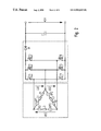
- FIG. 2 shows a second embodiment of the device according to the present invention.
- FIG. 3 shows a third embodiment of the device according to the present invention.
- FIG. 4 shows a fourth embodiment of the device according to the present invention.
- generator G (e.g., a claw-pole generator) includes stator inductors L 1 , L 2 and L 3 and resistors R 1 , R 2 and R 3 which represent the winding resistors.
- the generator produces phase voltages US 1 , US 2 , US 3 which are formed from synchronous generated voltages U 1 , U 2 , U 3 and the voltages at resistors R 1 , R 2 , R 3 and stator inductors L 1 , L 2 , L 3 .
- These voltages result in currents I 1 , I 2 , I 3 , which are rectified via diode bridge DB and in generator output current IG which serves to supply the vehicle electrical system loads.
- Generator G is controlled in the customary manner using a voltage regulator R, which regulates field current IF through field winding F in such a way that a specifiable voltage is obtained.
- Input signals E such as various voltages and/or currents and/or the generator rotational speed, are supplied to voltage regulator R.
- Voltage regulator R is capable of emitting output signals A with the aid of which switches or the like can be actuated, for example.
- a circuit arrangement SCH including a transistor T, a diode D and a capacitor C is connected to generator G.
- the circuit arrangement SCH makes the generator control according to the present invention possible in that transistor T, which is an MOS field effect transistor connected parallel to diode bridge DB, for example, short-circuits diode bridge DB from time to time.
- transistor T is made conducting or non-conducting using a pulse width modulation stage PWM, which is integrated in voltage regulator R.
- the pulse frequency of transistor T is in the medium frequency range and is determined by pulse width modulation stage PWM.
- This pulse width modulation stage does not necessarily have to be integrated into voltage regulator R, but rather it can, for example, be constructed as a separate stage or integrated in the electronic control unit of the vehicle. Other controls of transistor T are also conceivable.
- diode bridge DB With power transistor T causes the flow of power from generator G to battery B to be interrupted. This makes boosting of the generator possible.
- power is stored temporarily in stator inductors L 1 L 2 and L 3 of generator G.
- Diode D 1 prevents current from flowing back and short-circuiting and discharging the downstream electrical system or battery B. If transistor T blocks, the power stored in the stator inductors is released in the form of induced voltages which are combined with the respective synchronous generated voltages U 1 , U 2 and U 3 . This results in a higher output voltage of the generator.
- An output voltage of 42 V can be set by suitable variation of the conduction and blocking duration;. 42 volts charging voltage corresponds to 36 volts rated voltage.
- Capacitor C at the output of circuit arrangement SCH serves to smooth out the pulsed output current.
- circuit arrangement SCH may be designated as a generator step-up converter.
- the conventional vehicle electrical system must be supplied using a DC-DC voltage converter.
- Electrical system loads to be supplied with higher voltage a windshield heater R 4 , for example, can be directly connected to the 42 V via a switch S 1 Loads R 5 , on the other hand, can be connected to 12 V via switch S 2 .
- Each voltage level has a separate battery, which are identified in FIG. 1 as B 42 and B 12 .
- diode bridge DB should be designed so that it is suitable for 42 V.
- generator G must be designed so that an output voltage of 42 V is handled without problems.
- the voltage regulator or pulse width modulation stage PWM must be designed in such a way that necessary control signals can be generated. In a microprocessor-controlled system, the control signals can be supplied by the microprocessor which may also be the electronic control unit of the internal combustion engine.
- FIGS. 2 and 3 show two additional exemplary embodiments according to the present invention in which the field winding and the voltage regulator and the second voltage level, which are shown in FIG. 1 , are also basically present; however, they are not shown in detail.
- rectifier bridge BD has been replaced by a fully controlled bridge with six circuit breakers, transistors T 1 to T 6 , for example.
- Diode D 1 serves as a freewheeling diode which must be considered a component of the fully controlled bridge and is connected to capacitor C.
- the freewheeling diode has been replaced by an additional transistor T 7 which is also a component of the fully controlled bridge.
- FIGS. 2 and 3 illustrate two options for voltage adjustment, for a claw-pole generator to a higher electrical system voltage, for example, which are to be understood as a measure according to the present invention.
- the mode of operation of these circuits can be explained as follows:
- a simultaneous activation of the six circuit breakers or transistors T 1 to T 6 of the fully controlled bridge circuit brings about a boost of generator G.
- MOS field effect transistors for example, can be used as circuit breakers.
- power is temporarily stored in stator inductors L 1 , L 2 and L 3 and is released in the blocking phase of the transistors and results in an increase in phase voltages US 1 , US 2 and US 3 .
- generator G which is driven by a shaft of an internal combustion engine, to make a higher voltage available for the production of an electrical system voltage level of 42 V, for example, particularly in the lower rotational speed range.
- Diode D 1 of the exemplary embodiment shown in FIG. 2 prevents battery B 42 from also being short-circuited and discharged during the conducting phase of circuit breakers or transistors T 1 to T 7 .
- an additional circuit breaker an MOS field effect transistor T 7 is used instead of a diode.
- This switch is controlled in such a way that it has its blocking phase during the conducting phase of the transistors of the bridge circuit and has its conducting phase during their blocking phase.
- This method corresponds to a synchronous rectification.
- the output voltage can be regulated to 42 V by proper variation of the conducting and blocking time, for example by variation of the mark-to-space ratio, i.e., the ratio between conducting and non-conducting phases. Voltages other than 42 V can of course also be obtained if necessary.
- Capacitor C at the output of the integrated step-up converter T 1 to T 6 and D 1 , T 1 to T 6 , T 7 serves to smooth out the output voltage.
- the six circuit breakers are preferably controlled by pulse width modulation; however other control methods are possible.
- the deadbeat principle or a pulse sequence modulation can be considered as possible control methods.
- conventional components such as MOS field effect transistors, insulated gate bipolar transistors (IGBT) or bipolar transistors can be used as circuit breakers. If circuit breakers are used in the bridge circuit, it must be made certain that the switch has a freewheeling diode with an inverse-parallel connection. Since this is the case with an MOS field effect transistor as a result of the manufacturing process, this component is preferably used. If a component that does not have this body diode is used as a circuit breaker, a freewheeling diode must be used as a discrete component.
- FIG. 4 shows another exemplary embodiment of the present invention, in which the bridge rectifier of the generator contains three diodes D 2 , D 3 , D 4 , as well as three transistors T 8 , T 9 , T 10 .
- the rectification arrangement thus represents a rectifier and a set-up converter.
- a claw-pole generator having an integrated set-up converter can be provided.
- step-up converter which functions as a DC voltage converter
- the number of components may be reduced in comparison to the other exemplary embodiments of the present invention described above.
- the voltage drop at diode D 1 of the step-up converter shown in FIG. 2 is eliminated, making the power loss in the exemplary embodiment illustrated in FIG. 4 smaller than in the exemplary embodiment illustrated in FIG. 2 , and thus the power efficiency is improved.
- transistors T 8 , T 9 , T 10 are replaced by field-effect transistors, power efficiency is further improved, since the field-effect transistors have a smaller forward power losses in comparison to the diode losses.
- capacitor C smooths out the rectified outlet voltage of the generator.
- mains voltage UN which functions to supply load L, can be tapped off, the load being indicated symbolically for the vehicle electrical system user.
Abstract
Description
Claims (33)
Applications Claiming Priority (2)
| Application Number | Priority Date | Filing Date | Title |
|---|---|---|---|
| DE19745114 | 1997-10-11 | ||
| DE19804096 | 1998-02-03 |
Publications (1)
| Publication Number | Publication Date |
|---|---|
| US6924629B1 true US6924629B1 (en) | 2005-08-02 |
Family
ID=26040779
Family Applications (1)
| Application Number | Title | Priority Date | Filing Date |
|---|---|---|---|
| US09/169,060 Expired - Lifetime US6924629B1 (en) | 1997-10-11 | 1998-10-09 | Device and method for controlling a generator |
Country Status (5)
| Country | Link |
|---|---|
| US (1) | US6924629B1 (en) |
| JP (1) | JPH11196599A (en) |
| DE (1) | DE19845569A1 (en) |
| FR (1) | FR2769770B1 (en) |
| IT (1) | IT1302605B1 (en) |
Cited By (16)
| Publication number | Priority date | Publication date | Assignee | Title |
|---|---|---|---|---|
| US20040113593A1 (en) * | 2002-12-10 | 2004-06-17 | Denso Corporation | Generator control circuit having alarm controller |
| US20040174018A1 (en) * | 2003-03-06 | 2004-09-09 | Yasumitsu Itoh | Power generation controller for AC generator |
| US20060028778A1 (en) * | 2004-08-06 | 2006-02-09 | O'gorman Patrick A | Automotive electrical system |
| WO2006023426A3 (en) * | 2004-08-24 | 2006-05-04 | Motorola Inc | Automotive electrical system configuration using a two bus structure |
| US20080157726A1 (en) * | 2006-12-29 | 2008-07-03 | Chih-Huang Chen | Voltage regulating system and voltage regulator |
| US20080290843A1 (en) * | 2007-05-21 | 2008-11-27 | Honeywell International Inc. | Wide speed range electric power generation system using high reactance permanent magnet machine |
| US7514807B2 (en) * | 2005-04-25 | 2009-04-07 | Railpower Technologies Corp. | Alternator boost method |
| US20090243518A1 (en) * | 2008-04-01 | 2009-10-01 | Takao Itoh | Motive power output device, vehicle equipped with the device, and control method for motive power output device |
| US20090267419A1 (en) * | 2006-02-03 | 2009-10-29 | Henrik Stiesdal | Method for smoothing alternating electric current from a number of power generating units and wind power plant including a number of wind mills with variable rotational speed |
| US20100085106A1 (en) * | 2008-10-08 | 2010-04-08 | Semikron Elektronik Gmbh & Co., Kg | Method for Operating a Converter Circuit with Voltage Boosting |
| CN103650328A (en) * | 2011-05-10 | 2014-03-19 | 法雷奥电机设备公司 | Method of controlling a rotating electric machine, control system and rotating electric machine corresponding thereto |
| US20140203788A1 (en) * | 2011-09-01 | 2014-07-24 | Moteurs Leroy-Somer | Method for regulating a generator set |
| US8823208B2 (en) | 2011-11-16 | 2014-09-02 | C. E. Niehoff & Co. | Self-energizing voltage regulator with improved transient recovery |
| US9564845B2 (en) * | 2014-11-17 | 2017-02-07 | The Boeing Company | System and method for generator main field energy extraction |
| US20170066332A1 (en) * | 2015-09-04 | 2017-03-09 | Toyota Jidosha Kabushiki Kaisha | Vehicle |
| US10418926B2 (en) | 2017-11-06 | 2019-09-17 | The Boeing Company | Counter-field winding in electrical generator |
Families Citing this family (17)
| Publication number | Priority date | Publication date | Assignee | Title |
|---|---|---|---|---|
| DE19903426A1 (en) | 1999-01-29 | 2000-08-03 | Bosch Gmbh Robert | Device and method for regulating a generator with an associated voltage converter |
| FR2797535B1 (en) * | 1999-08-09 | 2001-10-12 | Leroy Somer | ELECTRICITY GENERATION DEVICE |
| DE19944833A1 (en) * | 1999-09-18 | 2001-03-22 | Bosch Gmbh Robert | Multi-voltage electrical power |
| DE10003731B4 (en) * | 2000-01-28 | 2012-01-26 | Robert Bosch Gmbh | Use of an electronic switching device for temporarily connecting a battery to a consumer in a two-voltage electrical system |
| DE10061047A1 (en) * | 2000-12-08 | 2002-06-13 | Bosch Gmbh Robert | Device for fault detection in a multi-voltage electrical system |
| DE10102344A1 (en) * | 2001-01-19 | 2002-08-01 | Bosch Gmbh Robert | Procedure for measuring the current in half bridges |
| DE10119985A1 (en) | 2001-04-24 | 2002-10-31 | Bosch Gmbh Robert | Device for feeding energy into a multi-voltage electrical system of a motor vehicle |
| FR2835106B1 (en) * | 2002-01-24 | 2004-09-03 | Peugeot Citroen Automobiles Sa | ELECTRIC POWER SUPPLY SYSTEM FOR A MOTOR VEHICLE |
| ES2357422T3 (en) | 2002-09-10 | 2011-04-26 | Dewind Co. | PROCEDURE FOR THE OPERATION OF A WIND ENERGY INSTALLATION WITH OVERCROWDED CASCADE. |
| WO2004066485A1 (en) * | 2003-01-20 | 2004-08-05 | Impex Honsberg | Power supply system comprising a step-up converter |
| JP4377164B2 (en) * | 2003-06-10 | 2009-12-02 | 株式会社日立製作所 | Power storage device abnormality detection method, power storage device abnormality detection device, and power storage system |
| DE102004036563A1 (en) * | 2004-07-28 | 2006-03-23 | Robert Bosch Gmbh | Device for voltage stabilization |
| FR2892077B1 (en) * | 2005-10-17 | 2009-05-15 | Peugeot Citroen Automobiles Sa | POWER SUPPLY CIRCUIT FOR ELECTRICAL POWER OF A MOTOR VEHICLE |
| DE102008008561A1 (en) | 2008-02-08 | 2009-08-13 | Robert Bosch Gmbh | Method for controlling an electrical vehicle electrical system and electrical system |
| JP5307814B2 (en) | 2008-07-17 | 2013-10-02 | 三菱電機株式会社 | Power supply |
| SI3264587T1 (en) | 2016-06-28 | 2021-08-31 | Martin Special Technics Gmbh | Energy generation system comprising a generator and method for operating such an energy generation system |
| US11476787B2 (en) | 2018-08-31 | 2022-10-18 | Honda Motor Co., Ltd. | Inverter type engine generator |
Citations (14)
| Publication number | Priority date | Publication date | Assignee | Title |
|---|---|---|---|---|
| US4079306A (en) * | 1975-07-22 | 1978-03-14 | Nippondenso Co., Ltd. | Current generating system for motor vehicle |
| US4733159A (en) * | 1986-10-28 | 1988-03-22 | Motorola, Inc. | Charge pump voltage regulator |
| US4825139A (en) * | 1986-07-04 | 1989-04-25 | Valeo | Electric power supply unit, in particular for a motor vehicle, and an electric rotary machine for such a unit |
| US4831322A (en) | 1987-05-07 | 1989-05-16 | Hitachi Ltd. | Voltage regulator for charger/generator |
| EP0325520A2 (en) | 1988-01-20 | 1989-07-26 | Saint-Gobain Vitrage International | Dual tension supply circuit for an automotive vehicle |
| EP0507663A1 (en) | 1991-04-05 | 1992-10-07 | Artus | Method and apparatus for attenuating the effect of conducted radiointerference on the polyphase AC network |
| US5448154A (en) * | 1992-07-03 | 1995-09-05 | Hitachi, Ltd. | Control device for battery charging AC generator used in motor vehicle |
| JPH0823642A (en) | 1994-07-05 | 1996-01-23 | Kokusan Denki Co Ltd | Power unit for internal combustion engine |
| US5543703A (en) * | 1993-12-24 | 1996-08-06 | Nippondenso Co., Ltd. | Generator motor for vehicles |
| EP0740389A1 (en) | 1995-04-24 | 1996-10-30 | Nippondenso Co., Ltd. | Generating apparatus |
| EP0777309A2 (en) | 1995-12-05 | 1997-06-04 | Denso Corporation | Generating apparatus for vehicle |
| US5726557A (en) * | 1995-06-06 | 1998-03-10 | Nippondenso Co., Ltd. | Vehicular electric power system |
| US5793625A (en) * | 1997-01-24 | 1998-08-11 | Baker Hughes Incorporated | Boost converter regulated alternator |
| US5942818A (en) * | 1998-02-06 | 1999-08-24 | Isuzu Ceramics Research Institute Co., Ltd. | Control apparatus for engine-driven permanent magnet type synchronous generators |
-
1998
- 1998-10-02 DE DE19845569A patent/DE19845569A1/en not_active Ceased
- 1998-10-06 IT IT1998MI002141A patent/IT1302605B1/en active IP Right Grant
- 1998-10-09 JP JP10287780A patent/JPH11196599A/en active Pending
- 1998-10-09 FR FR9812675A patent/FR2769770B1/en not_active Expired - Fee Related
- 1998-10-09 US US09/169,060 patent/US6924629B1/en not_active Expired - Lifetime
Patent Citations (15)
| Publication number | Priority date | Publication date | Assignee | Title |
|---|---|---|---|---|
| US4079306A (en) * | 1975-07-22 | 1978-03-14 | Nippondenso Co., Ltd. | Current generating system for motor vehicle |
| US4825139A (en) * | 1986-07-04 | 1989-04-25 | Valeo | Electric power supply unit, in particular for a motor vehicle, and an electric rotary machine for such a unit |
| US4733159A (en) * | 1986-10-28 | 1988-03-22 | Motorola, Inc. | Charge pump voltage regulator |
| US4831322A (en) | 1987-05-07 | 1989-05-16 | Hitachi Ltd. | Voltage regulator for charger/generator |
| EP0325520A2 (en) | 1988-01-20 | 1989-07-26 | Saint-Gobain Vitrage International | Dual tension supply circuit for an automotive vehicle |
| EP0507663A1 (en) | 1991-04-05 | 1992-10-07 | Artus | Method and apparatus for attenuating the effect of conducted radiointerference on the polyphase AC network |
| US5448154A (en) * | 1992-07-03 | 1995-09-05 | Hitachi, Ltd. | Control device for battery charging AC generator used in motor vehicle |
| US5543703A (en) * | 1993-12-24 | 1996-08-06 | Nippondenso Co., Ltd. | Generator motor for vehicles |
| JPH0823642A (en) | 1994-07-05 | 1996-01-23 | Kokusan Denki Co Ltd | Power unit for internal combustion engine |
| US5714871A (en) | 1994-07-05 | 1998-02-03 | Kokusan Denki Co., Ltd. | Power device for internal combustion engine |
| EP0740389A1 (en) | 1995-04-24 | 1996-10-30 | Nippondenso Co., Ltd. | Generating apparatus |
| US5726557A (en) * | 1995-06-06 | 1998-03-10 | Nippondenso Co., Ltd. | Vehicular electric power system |
| EP0777309A2 (en) | 1995-12-05 | 1997-06-04 | Denso Corporation | Generating apparatus for vehicle |
| US5793625A (en) * | 1997-01-24 | 1998-08-11 | Baker Hughes Incorporated | Boost converter regulated alternator |
| US5942818A (en) * | 1998-02-06 | 1999-08-24 | Isuzu Ceramics Research Institute Co., Ltd. | Control apparatus for engine-driven permanent magnet type synchronous generators |
Non-Patent Citations (1)
| Title |
|---|
| Comprehensive Dictionary of Electrical Engineering, pp. 68 and 611 (Philip A. Laplante ed., 1999). * |
Cited By (27)
| Publication number | Priority date | Publication date | Assignee | Title |
|---|---|---|---|---|
| US6992465B2 (en) * | 2002-12-10 | 2006-01-31 | Denso Corporation | Generator control circuit having alarm controller |
| US20040113593A1 (en) * | 2002-12-10 | 2004-06-17 | Denso Corporation | Generator control circuit having alarm controller |
| US20040174018A1 (en) * | 2003-03-06 | 2004-09-09 | Yasumitsu Itoh | Power generation controller for AC generator |
| US7023102B2 (en) * | 2003-03-06 | 2006-04-04 | Suzuki Motor Corporation | Power generation controller for AC generator |
| US20060028778A1 (en) * | 2004-08-06 | 2006-02-09 | O'gorman Patrick A | Automotive electrical system |
| US7701079B2 (en) | 2004-08-06 | 2010-04-20 | Continental Automotive Systems, Inc. | Automotive electrical system |
| WO2006023426A3 (en) * | 2004-08-24 | 2006-05-04 | Motorola Inc | Automotive electrical system configuration using a two bus structure |
| US7514807B2 (en) * | 2005-04-25 | 2009-04-07 | Railpower Technologies Corp. | Alternator boost method |
| US20090267419A1 (en) * | 2006-02-03 | 2009-10-29 | Henrik Stiesdal | Method for smoothing alternating electric current from a number of power generating units and wind power plant including a number of wind mills with variable rotational speed |
| US20080157726A1 (en) * | 2006-12-29 | 2008-07-03 | Chih-Huang Chen | Voltage regulating system and voltage regulator |
| US7772808B2 (en) * | 2006-12-29 | 2010-08-10 | Universal Scientific Industrial (Shanghai) Co., Ltd. | Voltage regulating system and voltage regulator |
| US7595612B2 (en) | 2007-05-21 | 2009-09-29 | Honeywell International Inc. | Wide speed range electric power generation system using high reactance permanent magnet machine |
| US20080290843A1 (en) * | 2007-05-21 | 2008-11-27 | Honeywell International Inc. | Wide speed range electric power generation system using high reactance permanent magnet machine |
| US20090243518A1 (en) * | 2008-04-01 | 2009-10-01 | Takao Itoh | Motive power output device, vehicle equipped with the device, and control method for motive power output device |
| US7836985B2 (en) * | 2008-04-01 | 2010-11-23 | Toyota Jidosha Kabushiki Kaisha | Motive power output device, vehicle equipped with the device, and control method for motive power output device |
| US20100085106A1 (en) * | 2008-10-08 | 2010-04-08 | Semikron Elektronik Gmbh & Co., Kg | Method for Operating a Converter Circuit with Voltage Boosting |
| DE102008042693A1 (en) * | 2008-10-08 | 2010-04-15 | Semikron Elektronik Gmbh & Co. Kg | Method for operating a power converter circuit with voltage increase |
| US8183909B2 (en) | 2008-10-08 | 2012-05-22 | Semikron Elektronik Gmbh & Co. Kg | Method for operating a converter circuit with voltage boosting |
| DE102008042693B4 (en) * | 2008-10-08 | 2015-10-08 | Semikron Elektronik Gmbh & Co. Kg | Method for operating a power converter circuit with voltage increase |
| CN103650328A (en) * | 2011-05-10 | 2014-03-19 | 法雷奥电机设备公司 | Method of controlling a rotating electric machine, control system and rotating electric machine corresponding thereto |
| US20140203788A1 (en) * | 2011-09-01 | 2014-07-24 | Moteurs Leroy-Somer | Method for regulating a generator set |
| US9595901B2 (en) * | 2011-09-01 | 2017-03-14 | Moteurs Leroy-Somer | Method for regulating a generator set |
| US8823208B2 (en) | 2011-11-16 | 2014-09-02 | C. E. Niehoff & Co. | Self-energizing voltage regulator with improved transient recovery |
| US9564845B2 (en) * | 2014-11-17 | 2017-02-07 | The Boeing Company | System and method for generator main field energy extraction |
| US20170066332A1 (en) * | 2015-09-04 | 2017-03-09 | Toyota Jidosha Kabushiki Kaisha | Vehicle |
| US10181808B2 (en) * | 2015-09-04 | 2019-01-15 | Toyota Jidosha Kabushiki Kaisha | Vehicle |
| US10418926B2 (en) | 2017-11-06 | 2019-09-17 | The Boeing Company | Counter-field winding in electrical generator |
Also Published As
| Publication number | Publication date |
|---|---|
| JPH11196599A (en) | 1999-07-21 |
| ITMI982141A1 (en) | 2000-04-06 |
| IT1302605B1 (en) | 2000-09-29 |
| FR2769770A1 (en) | 1999-04-16 |
| DE19845569A1 (en) | 1999-04-15 |
| FR2769770B1 (en) | 2003-10-24 |
Similar Documents
| Publication | Publication Date | Title |
|---|---|---|
| US6924629B1 (en) | Device and method for controlling a generator | |
| US8138694B2 (en) | Bidirectional buck-boost power converters | |
| US6002603A (en) | Balanced boost/buck DC to DC converter | |
| US6982499B1 (en) | Power converting method and apparatus | |
| JP3634443B2 (en) | Inductive load control circuit | |
| US6111768A (en) | Multiple voltage alternator system | |
| US8541989B2 (en) | Power supply apparatus | |
| JP2007523587A (en) | DC-DC voltage regulator whose switching frequency is responsive to the load | |
| JP2003520557A (en) | Load matching alternator system | |
| KR20060106878A (en) | Dc voltage converter with several isolated regulated outputs | |
| US6335575B1 (en) | Electrical voltage supply system | |
| US5977753A (en) | Buck regulator with plural outputs | |
| JP3135581B2 (en) | Automotive network | |
| JPH09233709A (en) | Charger for electric car | |
| GB2294165A (en) | Power supply for providing a dc supply from a multiphase ac source | |
| CA2853556A1 (en) | Double-rectifier for a multi-phase contactless energy transmission system | |
| EP0740389B1 (en) | Generating apparatus | |
| US6707275B2 (en) | Automative generator control apparatus | |
| US6222743B1 (en) | Power factor correction circuit | |
| JP4191874B2 (en) | Uninterruptible power system | |
| EP0684754B1 (en) | A power supply circuit, particularly for motor vehicles | |
| CN113632380A (en) | Power electronic device and method for supplying voltage to a drive circuit of a power semiconductor switch | |
| JP2005522974A (en) | Equipment for inductive transmission of electric power | |
| JP2000078842A (en) | Dc converter | |
| JP2850742B2 (en) | Charger |
Legal Events
| Date | Code | Title | Description |
|---|---|---|---|
| AS | Assignment |
Owner name: ROBERT BOSCH GMBH, GERMANY Free format text: ASSIGNMENT OF ASSIGNORS INTEREST;ASSIGNORS:MUELLER, WOLFGANG;LUZ, OLIVER;SCHOETTLE, RICHARD;REEL/FRAME:009685/0799 Effective date: 19981208 |
|
| STCF | Information on status: patent grant |
Free format text: PATENTED CASE |
|
| CC | Certificate of correction | ||
| FPAY | Fee payment |
Year of fee payment: 4 |
|
| FPAY | Fee payment |
Year of fee payment: 8 |
|
| SULP | Surcharge for late payment |
Year of fee payment: 7 |
|
| FPAY | Fee payment |
Year of fee payment: 12 |
|
| AS | Assignment |
Owner name: SEG AUTOMOTIVE GERMANY GMBH, GERMANY Free format text: ASSIGNMENT OF ASSIGNORS INTEREST;ASSIGNOR:ROBERT BOSCH GMBH;REEL/FRAME:044510/0921 Effective date: 20171023 |