US6949071B1 - Method for exploring and displaying tissue of human or animal origin from a high frequency ultrasound probe - Google Patents
Method for exploring and displaying tissue of human or animal origin from a high frequency ultrasound probe Download PDFInfo
- Publication number
- US6949071B1 US6949071B1 US09/600,073 US60007301A US6949071B1 US 6949071 B1 US6949071 B1 US 6949071B1 US 60007301 A US60007301 A US 60007301A US 6949071 B1 US6949071 B1 US 6949071B1
- Authority
- US
- United States
- Prior art keywords
- tissue
- probe
- ultrasound
- scanned
- scan
- Prior art date
- Legal status (The legal status is an assumption and is not a legal conclusion. Google has not performed a legal analysis and makes no representation as to the accuracy of the status listed.)
- Expired - Fee Related
Links
Images


Classifications
-
- A—HUMAN NECESSITIES
- A61—MEDICAL OR VETERINARY SCIENCE; HYGIENE
- A61B—DIAGNOSIS; SURGERY; IDENTIFICATION
- A61B8/00—Diagnosis using ultrasonic, sonic or infrasonic waves
- A61B8/44—Constructional features of the ultrasonic, sonic or infrasonic diagnostic device
- A61B8/4483—Constructional features of the ultrasonic, sonic or infrasonic diagnostic device characterised by features of the ultrasound transducer
-
- A—HUMAN NECESSITIES
- A61—MEDICAL OR VETERINARY SCIENCE; HYGIENE
- A61B—DIAGNOSIS; SURGERY; IDENTIFICATION
- A61B8/00—Diagnosis using ultrasonic, sonic or infrasonic waves
- A61B8/10—Eye inspection
-
- G—PHYSICS
- G01—MEASURING; TESTING
- G01S—RADIO DIRECTION-FINDING; RADIO NAVIGATION; DETERMINING DISTANCE OR VELOCITY BY USE OF RADIO WAVES; LOCATING OR PRESENCE-DETECTING BY USE OF THE REFLECTION OR RERADIATION OF RADIO WAVES; ANALOGOUS ARRANGEMENTS USING OTHER WAVES
- G01S15/00—Systems using the reflection or reradiation of acoustic waves, e.g. sonar systems
- G01S15/88—Sonar systems specially adapted for specific applications
- G01S15/89—Sonar systems specially adapted for specific applications for mapping or imaging
- G01S15/8906—Short-range imaging systems; Acoustic microscope systems using pulse-echo techniques
- G01S15/8993—Three dimensional imaging systems
Definitions
- the present invention relates to a process for the investigation and display, using ultrasound echography techniques, of tissue structures of human or animal origin such as in particular the ocular globes and more particularly of the posterior segment (the vitreous cavity, the posterior wall of the globe lined by the choroid and the retina, the macula), tissue structures of the anterior segment (the cornea, the anterior chamber, the iris and the crystalline lens).
- tissue structures of human or animal origin such as in particular the ocular globes and more particularly of the posterior segment (the vitreous cavity, the posterior wall of the globe lined by the choroid and the retina, the macula), tissue structures of the anterior segment (the cornea, the anterior chamber, the iris and the crystalline lens).
- the invention also relates to a device and an ultrasound probe which allow this investigation and this display to be achieved in 2D or 3D.
- the choice of frequency is dictated by the compromise between resolution and penetration depth. Specifically, because of the increase in attenuation of ultrasound waves with frequency, the penetration depth of ultrasound increases with decreasing frequency. However, the image resolution decreases with decreasing frequency.
- the major drawback of low-frequency echography is mainly the low resolution (600 to 700 ⁇ m) provided by these low frequencies, which do not allow detailed analysis of the retina and the other layers of the posterior wall of the eye (choroid and sclera) and more particularly in the macular region.
- the present invention aims to alleviate the drawbacks of the known processes of the prior art, by proposing an investigation and display process using a high-frequency ultrasound probe which combines both very high spatial resolution and a field of investigation covering the anterior and posterior segments of the ocular globe.
- the probe is excited such that it generates wave beams whose nominal frequency is included within the range from 30 to 100 MHz with a broad bandwidth, adapted to the frequencies reflected by the structure investigated.
- the wave beams are focused over a vertical penetration distance of between 20 and 30 mm.
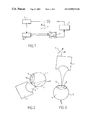
- FIG. 1 is a synoptic view of a device enabling the process forming the subject of the invention to be implemented;
- FIG. 2 is a view illustrating a use of the process forming the subject of the invention for the investigation of the posterior segment of an ocular globe;
- FIG. 3 is a view illustrating a use of the process forming the subject of the invention for the investigation of the anterior segment of an ocular globe;
- FIGS. 4 a and 4 b illustrate, on one hand, a front view of one embodiment of the ultrasound probe consisting of an annular array whose focus point can be modified electronically and, on the other hand, a side view of this same probe into which a phase difference has been introduced at transmission or at reception between the various rings making up the array;
- FIG. 5 is a view illustrating a use of the process forming the subject of the invention for the investigation of the anterior segment of an ocular globe, using a dynamic focusing probe;
- FIG. 6 is a view illustrating a use of the process forming the subject of the invention for the investigation of the posterior segment of an ocular globe, using a dynamic focusing probe;
- FIG. 7 shows a comparison between a macular section of a human globe in vitro, obtained by macroscopic histological imaging (right side) and an image arising from the process forming the subject of the invention (left side) where P represents the retinal folds, R the retina, S the sclera and V the vitreous humour;
- FIG. 8 is the image obtained from an anterior segment of a rabbit's eye, by the process forming the subject of the invention, where C represents the cornea, I the iris, S the sclera and Cr the anterior surface of the lens.
- the process consists in positioning an ultrasound probe 1 mounted within a head articulated in three dimensions X, Y, Z, at least one direction of which can be fixed, this head being steered by a servo-controlled positioning system 2 , controlled by a computer 3 , in particular in a direction perpendicular to the medium to be investigated.
- This ultrasound probe 1 consists mainly of a transducer, in particular one made of PVDF (polyvinylidene difluoride), controlled by a transmitter/receiver 4 , in order to generate beams of convergent, broadband, ultrasonic waves, these waves being able to adopt a spherical or linear profile.
- PVDF polyvinylidene difluoride
- FIG. 2 shows an investigation of the posterior segment of an ocular globe 5 , previously inserted into a coupling medium 6 which does not impair the propagation of the waves, especially in the retina region.
- a probe 1 positioned on the pars plana 7 is used to avoid absorption of the ultrasound beam by the lens 8 (this lens also marking the boundary between the posterior segment 9 and the anterior segment 10 of an ocular globe 5 ).
- This probe 1 transmits beams of ultrasound waves set within a nominal broadband frequency range varying from 30 to 100 MHz, involving wavelengths going from 50 to 15 am, focused at a focal length or between 70 and 30 mm and preferably 25 mm, corresponding in fact to a focus at an average depth or an ocular globe.
- the receiving system will have a bandwidth adapted to the frequencies reflected by the structure, these frequencies being lower than the transmitted frequencies because of the attenuation by the medium which is crossed.
- this same probe 1 is used under the same control conditions as previously, in a position offset on the vertical axis (Z axis) at a distance corresponding in fact to the previous focal length.
- the focal length is not modified by a mechanical servocontrol 2 in the position, but by an electronic or digital device steering the probe and able to modify, by careful command, the focusing area of the probe, in order thus to obtain simultaneously a high resolution image of the anterior segment and of the posterior segment of the eye.
- This probe with dynamic focusing carried out by an electronic or digital control process, consists of a multi-element probe, with circular symmetry, made up of several concentric annular transducers evenly spaced over a plane surface or with spherical concavity (refer to FIG. 4 a ). These transducers are independent of each other and are controlled individually in transmission and in reception by pulses which are offset in time (refer to FIG. 4 b which shows dynamic focusing obtained by introducing a phase difference—time delay—into the transmission between the various rings).
- the generated wavefront is convergent and its curvature is modified according to the distance between the structure investigated and the probe.
- the peripheral rings transmit first and the excitation of the central ring is the most retarded.
- the focal length along the axis of the probe can be varied and is therefore determined by the phase difference or the time delay introduced between the various transducers.
- the same principle of dynamic focusing is used in reception; the electronic delay is adjusted to the depth of the echoes which arrive at that moment at the probe. In this way the depth of field is increased without in any way degrading the lateral resolution.
- a measurement system of which each of the components (digitizer 11 , computer 3 , control electronics 2 , transmitter/receiver 4 , etc.) forming it has a bandwidth compatible with the processing and analysis of the signals originating from the anterior segment and/or of the signals coming from the posterior segment of the eye, enables processing of the signals backscattered by the structure investigated.
- the backscattered ultrasound signal is amplified then digitized using the digitizer 11 , at a given sampling frequency (in particular of the order of 400 MHz over 8 bits).
- This same computer controls the stepper on DC motors in order to move the probe and scan the ultrasound beams over the sample in a defined step along X and along Y in order to allow another measurement point or in an R, ⁇ step using a probe support head which allows an arciform scan.
- the computer is fitted with a module for processing the image and the radiofrequency signal.
- This module has programmed software which enables the two quantitative approaches, of 2D and/or 3D biometry and of tissue characterization, to be carried out.
- the echographic signal can be shown in real time in the form of a A-scan line or in the form of a 2D image of the B-scan type.
- the B-scan images can display sections in the various planes parallel to the direction of propagation of the ultrasound (cf. FIGS. 7 and 8 ).
- a 2D image of the C-scan type can also be calculated in order to display sections in the plane perpendicular to the direction of propagation of the ultrasound.
- the C-scan is able to show sections located at different depths of the whole ocular globe.
- the calculation and the reconstruction of the 3D image can be carried out using programmed mathematical functions specific to the ultrasound data to be processed.
- the processing software of the radiofrequency signal enables a frequency analysis of the digitized and recorded backscattered signals to be made in order to calculate quantitative ultrasound parameters for the purpose of tissue characterization.
- These parameters are in particular the attenuation coefficient in dB/cm.MHz (decibels/cm.megahertz), the overall attenuation coefficient in dB/cm, the backscatter coefficient in dB/cm.MHz and the overall backscatter coefficient in dB/cm.
- the images obtained by this investigation process both for an ocular globe and the region of the anterior segment and the posterior segment, have a resolution which is improved by a factor of at least two to three compared with that obtained with conventional echographs and are not limited by the transparency of the media investigated as in particular with conventional optical investigation means (biomicroscopy, angiography) whose quality can be affected by the presence of cataracts and haemorrhages.
- FIG. 7 illustrates the similarities between a histological image and an echographic image of the macula of a human eye (in vitro), and FIG. 8 illustrates an image of an anterior segment of a rabbit's eye.
- the process and the device which enables its implementation, such as those described previously, are not limited to applications in ophthalmology, but they can also find applications in gynaecology and obstetrics, in gastro-enterology and in the field of cardiovascular examinations and examinations by coelioscopy, or in dermatology and more generally in any medium which reflects a usable signal.
- the focus point or focusing area of the wave beam will be adjusted within a range going from a few tenths of a millimeter to several millimeters and the waveband used will be between 30 and 100 MHz.
Abstract
Description
-
- an ultrasound probe is positioned, said probe being carried by a head steered by means of a three-dimensional positioning system, in particular a system controlled by a computer at right angles to said tissue structure,
- the probe is controlled such that it generates beams of convergent high-frequency ultrasound waves whose nominal frequency is included within the range from 30 to 100 MHz with a broad bandwidth, adapted to the frequencies reflected by the structure investigated, these waves being focused on a given area of tissue structure,
- the tissue structure is scanned by the positioning system steered by the computer, while said computer carries out, in parallel, the acquisition of the signals reflected by the tissue structure,
- various signal processing operations are carried out on the data coming from the scanning, to improve the reproduction of the information and to facilitate the interpretation thereof by the practitioner.
Claims (11)
Priority Applications (1)
| Application Number | Priority Date | Filing Date | Title |
|---|---|---|---|
| US11/182,853 US20050251043A1 (en) | 1998-01-12 | 2005-07-18 | Method for exploring and displaying tissues fo human or animal origin from a high frequency ultrasound probe |
Applications Claiming Priority (2)
| Application Number | Priority Date | Filing Date | Title |
|---|---|---|---|
| FR9800209A FR2773459B1 (en) | 1998-01-12 | 1998-01-12 | PROCESS FOR EXPLORING AND VISUALIZING TISSUES OF HUMAN OR ANIMAL ORIGIN FROM A HIGH FREQUENCY ULTRASONIC SENSOR |
| PCT/FR1999/000040 WO1999034733A1 (en) | 1998-01-12 | 1999-01-12 | Method for exploring and displaying tissues of human or animal origin from a high frequency ultrasound probe |
Related Child Applications (1)
| Application Number | Title | Priority Date | Filing Date |
|---|---|---|---|
| US11/182,853 Continuation US20050251043A1 (en) | 1998-01-12 | 2005-07-18 | Method for exploring and displaying tissues fo human or animal origin from a high frequency ultrasound probe |
Publications (1)
| Publication Number | Publication Date |
|---|---|
| US6949071B1 true US6949071B1 (en) | 2005-09-27 |
Family
ID=9521666
Family Applications (2)
| Application Number | Title | Priority Date | Filing Date |
|---|---|---|---|
| US09/600,073 Expired - Fee Related US6949071B1 (en) | 1998-01-12 | 1999-01-12 | Method for exploring and displaying tissue of human or animal origin from a high frequency ultrasound probe |
| US11/182,853 Abandoned US20050251043A1 (en) | 1998-01-12 | 2005-07-18 | Method for exploring and displaying tissues fo human or animal origin from a high frequency ultrasound probe |
Family Applications After (1)
| Application Number | Title | Priority Date | Filing Date |
|---|---|---|---|
| US11/182,853 Abandoned US20050251043A1 (en) | 1998-01-12 | 2005-07-18 | Method for exploring and displaying tissues fo human or animal origin from a high frequency ultrasound probe |
Country Status (9)
| Country | Link |
|---|---|
| US (2) | US6949071B1 (en) |
| EP (2) | EP1047340A1 (en) |
| JP (1) | JP2002500059A (en) |
| KR (1) | KR100647025B1 (en) |
| AU (1) | AU1974399A (en) |
| CA (1) | CA2317474A1 (en) |
| FR (1) | FR2773459B1 (en) |
| NZ (1) | NZ506299A (en) |
| WO (1) | WO1999034733A1 (en) |
Cited By (22)
| Publication number | Priority date | Publication date | Assignee | Title |
|---|---|---|---|---|
| US20040122319A1 (en) * | 2002-10-10 | 2004-06-24 | Mehi James I. | High frequency, high frame-rate ultrasound imaging system |
| US20050240102A1 (en) * | 2002-07-12 | 2005-10-27 | Daniel Rachlin | Ultrasound interfacing device for tissue imaging |
| US20060173314A1 (en) * | 2003-02-19 | 2006-08-03 | Leblanc Paul D | Hand-held ophthalmic device |
| WO2007085073A1 (en) * | 2006-01-25 | 2007-08-02 | Jaltec Biomedical Inc. | Ultrasound method and apparatus for characterizing and identifying biological tissues |
| US20070239001A1 (en) * | 2005-11-02 | 2007-10-11 | James Mehi | High frequency array ultrasound system |
| US7291109B1 (en) * | 2004-10-25 | 2007-11-06 | Sarvazyan Armen P | Infant hydration monitor |
| US20080081996A1 (en) * | 2006-09-29 | 2008-04-03 | Grenon Stephen M | Meibomian gland imaging |
| US20080081999A1 (en) * | 2006-09-29 | 2008-04-03 | Gravely Benjamin T | Meibomian gland illuminating and imaging |
| WO2010039465A2 (en) * | 2008-09-23 | 2010-04-08 | Elc Management Llc | Methods of measuring human body frequencies or harmonics and treating conditions based on the resonance phenomenon between a product and a human body's frequencies or harmonics |
| CN101229068B (en) * | 2008-02-06 | 2010-06-02 | 温州医学院眼视光研究院 | Lentis three-dimensional imaging ultrasonography method |
| US7830069B2 (en) | 2004-04-20 | 2010-11-09 | Sunnybrook Health Sciences Centre | Arrayed ultrasonic transducer |
| US8316518B2 (en) | 2008-09-18 | 2012-11-27 | Visualsonics Inc. | Methods for manufacturing ultrasound transducers and other components |
| CN103079475A (en) * | 2010-07-07 | 2013-05-01 | 西江大学校产学协力团 | Method for generating ultrasonic image using concave array |
| US20140268036A1 (en) * | 2013-03-13 | 2014-09-18 | The Trustees Of Columbia University In The City Of New York | Methods for diagnosing vitreo-retinal disease |
| US9173047B2 (en) | 2008-09-18 | 2015-10-27 | Fujifilm Sonosite, Inc. | Methods for manufacturing ultrasound transducers and other components |
| US9184369B2 (en) | 2008-09-18 | 2015-11-10 | Fujifilm Sonosite, Inc. | Methods for manufacturing ultrasound transducers and other components |
| US9402366B2 (en) | 2007-05-17 | 2016-08-02 | Amo Development, Llc | Customized laser epithelial ablation systems and methods |
| WO2018031812A1 (en) | 2016-08-10 | 2018-02-15 | Amo Development, Llc | Epithelial ablation systems and methods |
| US10278587B2 (en) | 2013-05-03 | 2019-05-07 | Tearscience, Inc. | Eyelid illumination systems and method for imaging meibomian glands for meibomian gland analysis |
| US10970921B2 (en) | 2016-09-30 | 2021-04-06 | University Hospitals Cleveland Medical Center | Apparatus and method for constructing a virtual 3D model from a 2D ultrasound video |
| US11259700B2 (en) | 2009-04-01 | 2022-03-01 | Tearscience Inc | Ocular surface interferometry (OSI) for imaging, processing, and/or displaying an ocular tear film |
| CN114947963A (en) * | 2022-06-17 | 2022-08-30 | 中国医学科学院生物医学工程研究所 | Method and device for measuring axis of eye, storage medium and computer equipment |
Families Citing this family (9)
| Publication number | Priority date | Publication date | Assignee | Title |
|---|---|---|---|---|
| GB0015250D0 (en) * | 2000-06-22 | 2000-08-16 | Payne Peter A | Ophthalmic uses of lasers |
| US7178530B2 (en) * | 2002-10-25 | 2007-02-20 | Rines Robert H | Method of ameliorating vision-inhibiting effects of cataracts and the like |
| JP4916779B2 (en) * | 2005-09-29 | 2012-04-18 | 株式会社トプコン | Fundus observation device |
| WO2009042867A1 (en) * | 2007-09-27 | 2009-04-02 | University Of Southern California | High frequency ultrasonic convex array transducers and tissue imaging |
| FR2934695B1 (en) * | 2008-07-31 | 2011-07-15 | Intelligence In Medical Technologies | METHOD AND SYSTEM FOR CENTRALIZING IMAGE CONSTRUCTION |
| US11464482B2 (en) * | 2013-03-04 | 2022-10-11 | Sunnybrook Research Institute | System and method for measuring and correcting ultrasound phase distortions induced by aberrating media |
| JP2015047354A (en) * | 2013-09-02 | 2015-03-16 | セイコーエプソン株式会社 | Ultrasonic measurement apparatus and ultrasonic measurement method |
| FR3063003A1 (en) | 2017-02-22 | 2018-08-24 | Quantel Medical | OCULAR ULTRALOGRAPHY METHOD WITH ANNULAR TRANSDUCERS |
| KR102260156B1 (en) * | 2018-10-26 | 2021-06-07 | 연세대학교 원주산학협력단 | Accurate radiation dose assessment method for skin |
Citations (9)
| Publication number | Priority date | Publication date | Assignee | Title |
|---|---|---|---|---|
| US4167180A (en) * | 1975-05-01 | 1979-09-11 | The Commonwealth Of Australia, Care Of The Department Of Health | Method and apparatus for ultrasonic examination |
| US5165415A (en) * | 1985-09-27 | 1992-11-24 | Bio-Rad Laboratories, Inc. | Self contained hand held ultrasonic instrument for ophthalmic use |
| US5293871A (en) * | 1993-05-05 | 1994-03-15 | Cornell Research Foundation Inc. | System for ultrasonically determining corneal layer thicknesses and shape |
| US5551432A (en) * | 1995-06-19 | 1996-09-03 | New York Eye & Ear Infirmary | Scanning control system for ultrasound biomicroscopy |
| US6055452A (en) * | 1994-10-24 | 2000-04-25 | Transcan Research & Development Co., Ltd. | Tissue characterization based on impedance images and on impedance measurements |
| US6059728A (en) * | 1997-01-02 | 2000-05-09 | Storz Instrument Co. | Three-dimensional ultrasound imaging system and probe |
| US6159153A (en) * | 1998-12-31 | 2000-12-12 | Duke University | Methods and systems for ultrasound scanning using spatially and spectrally separated transmit ultrasound beams |
| US6312381B1 (en) * | 1999-09-14 | 2001-11-06 | Acuson Corporation | Medical diagnostic ultrasound system and method |
| US6352507B1 (en) * | 1999-08-23 | 2002-03-05 | G.E. Vingmed Ultrasound As | Method and apparatus for providing real-time calculation and display of tissue deformation in ultrasound imaging |
Family Cites Families (15)
| Publication number | Priority date | Publication date | Assignee | Title |
|---|---|---|---|---|
| US3948248A (en) * | 1974-09-05 | 1976-04-06 | Zuckerman Joel L | Method of measuring ocular pulse |
| CA1201197A (en) * | 1975-09-15 | 1986-02-25 | Commonwealth Of Australia (The) | Variable focus transducer |
| US4223560A (en) * | 1979-01-02 | 1980-09-23 | New York Institute Of Technology | Variable delay system |
| JPS57126066U (en) * | 1981-02-02 | 1982-08-06 | ||
| DE3119295A1 (en) * | 1981-05-14 | 1982-12-16 | Siemens AG, 1000 Berlin und 8000 München | DEVICE FOR DESTROYING CONCRETE IN BODIES |
| US4519260A (en) * | 1982-02-18 | 1985-05-28 | The Board Of Trustees Of The Leland Stanford Junior University | Ultrasonic transducers and applications thereof |
| JPS58157454A (en) * | 1982-03-15 | 1983-09-19 | 株式会社東芝 | Ultrasonic diagnostic apparatus |
| US4569231A (en) * | 1984-07-09 | 1986-02-11 | General Electric Company | Multiple frequency annular transducer array and system |
| JPS62113512U (en) * | 1985-11-29 | 1987-07-20 | ||
| FR2620327B1 (en) | 1987-09-11 | 1989-12-08 | Synthelabo | ARTICULATED HEAD ECHOGRAPHY PROBE |
| US5228004A (en) * | 1988-12-21 | 1993-07-13 | Ngk Insulators, Ltd. | Ultrasonic testing method |
| JPH02280749A (en) * | 1989-04-24 | 1990-11-16 | Fuji Electric Co Ltd | Supersonic wave probe |
| JP3373602B2 (en) * | 1993-08-05 | 2003-02-04 | 株式会社東芝 | Ultrasound therapy equipment |
| US5941825A (en) * | 1996-10-21 | 1999-08-24 | Philipp Lang | Measurement of body fat using ultrasound methods and devices |
| FR2772590B1 (en) * | 1997-12-18 | 2000-04-14 | Michel Puech | USE OF AN ULTRASONIC TRANSDUCER FOR ECHOGRAPHIC EXPLORATION OF THE POSTERIOR SEGMENT OF THE EYEBALL |
-
1998
- 1998-01-12 FR FR9800209A patent/FR2773459B1/en not_active Expired - Lifetime
-
1999
- 1999-01-12 NZ NZ506299A patent/NZ506299A/en unknown
- 1999-01-12 US US09/600,073 patent/US6949071B1/en not_active Expired - Fee Related
- 1999-01-12 JP JP2000527189A patent/JP2002500059A/en active Pending
- 1999-01-12 WO PCT/FR1999/000040 patent/WO1999034733A1/en active IP Right Grant
- 1999-01-12 EP EP99900521A patent/EP1047340A1/en not_active Ceased
- 1999-01-12 AU AU19743/99A patent/AU1974399A/en not_active Abandoned
- 1999-01-12 EP EP03290585A patent/EP1329193A3/en not_active Withdrawn
- 1999-01-12 CA CA002317474A patent/CA2317474A1/en not_active Abandoned
- 1999-01-12 KR KR1020007007657A patent/KR100647025B1/en not_active IP Right Cessation
-
2005
- 2005-07-18 US US11/182,853 patent/US20050251043A1/en not_active Abandoned
Patent Citations (9)
| Publication number | Priority date | Publication date | Assignee | Title |
|---|---|---|---|---|
| US4167180A (en) * | 1975-05-01 | 1979-09-11 | The Commonwealth Of Australia, Care Of The Department Of Health | Method and apparatus for ultrasonic examination |
| US5165415A (en) * | 1985-09-27 | 1992-11-24 | Bio-Rad Laboratories, Inc. | Self contained hand held ultrasonic instrument for ophthalmic use |
| US5293871A (en) * | 1993-05-05 | 1994-03-15 | Cornell Research Foundation Inc. | System for ultrasonically determining corneal layer thicknesses and shape |
| US6055452A (en) * | 1994-10-24 | 2000-04-25 | Transcan Research & Development Co., Ltd. | Tissue characterization based on impedance images and on impedance measurements |
| US5551432A (en) * | 1995-06-19 | 1996-09-03 | New York Eye & Ear Infirmary | Scanning control system for ultrasound biomicroscopy |
| US6059728A (en) * | 1997-01-02 | 2000-05-09 | Storz Instrument Co. | Three-dimensional ultrasound imaging system and probe |
| US6159153A (en) * | 1998-12-31 | 2000-12-12 | Duke University | Methods and systems for ultrasound scanning using spatially and spectrally separated transmit ultrasound beams |
| US6352507B1 (en) * | 1999-08-23 | 2002-03-05 | G.E. Vingmed Ultrasound As | Method and apparatus for providing real-time calculation and display of tissue deformation in ultrasound imaging |
| US6312381B1 (en) * | 1999-09-14 | 2001-11-06 | Acuson Corporation | Medical diagnostic ultrasound system and method |
Non-Patent Citations (3)
| Title |
|---|
| C. Passman and H. Ermert, "Adaptive 150 MHz Ultrasound Imaging of the Skin and the Eye Using an Optimal Combination of Short Pulse Mode and Pulse Compression Mode," 1995 IEEE Ultrasonics Symposium, 1995, pp. 1291-1294. |
| Foster, F.S., et al., "Ultrasound Backscatter Microscopy of the Eye In Vivo," 1990 Ultrasonics Symposium, Proceedings, Dec. 4-7, 1990, vol. 3, pp. 1481-1484. |
| Lizzi, F.L., et al., "Ultrasonic Therapy and Imaging in Ophthalmology," Acoustical Imaging, vol. 14, pp. 1-15, 1985. |
Cited By (43)
| Publication number | Priority date | Publication date | Assignee | Title |
|---|---|---|---|---|
| US20050240102A1 (en) * | 2002-07-12 | 2005-10-27 | Daniel Rachlin | Ultrasound interfacing device for tissue imaging |
| US7931596B2 (en) * | 2002-07-12 | 2011-04-26 | Iscience Interventional Corporation | Ultrasound interfacing device for tissue imaging |
| US20040122319A1 (en) * | 2002-10-10 | 2004-06-24 | Mehi James I. | High frequency, high frame-rate ultrasound imaging system |
| US8827907B2 (en) | 2002-10-10 | 2014-09-09 | Fujifilm Sonosite, Inc. | High frequency, high frame-rate ultrasound imaging system |
| US20060173314A1 (en) * | 2003-02-19 | 2006-08-03 | Leblanc Paul D | Hand-held ophthalmic device |
| US7830069B2 (en) | 2004-04-20 | 2010-11-09 | Sunnybrook Health Sciences Centre | Arrayed ultrasonic transducer |
| US7291109B1 (en) * | 2004-10-25 | 2007-11-06 | Sarvazyan Armen P | Infant hydration monitor |
| US20070239001A1 (en) * | 2005-11-02 | 2007-10-11 | James Mehi | High frequency array ultrasound system |
| US7901358B2 (en) | 2005-11-02 | 2011-03-08 | Visualsonics Inc. | High frequency array ultrasound system |
| USRE46185E1 (en) | 2005-11-02 | 2016-10-25 | Fujifilm Sonosite, Inc. | High frequency array ultrasound system |
| US20070238991A1 (en) * | 2006-01-25 | 2007-10-11 | Jaltec Biomedical Inc. | Ultrasound method and apparatus for characterizing and identifying biological tissues |
| WO2007085073A1 (en) * | 2006-01-25 | 2007-08-02 | Jaltec Biomedical Inc. | Ultrasound method and apparatus for characterizing and identifying biological tissues |
| US20080081999A1 (en) * | 2006-09-29 | 2008-04-03 | Gravely Benjamin T | Meibomian gland illuminating and imaging |
| US20080081996A1 (en) * | 2006-09-29 | 2008-04-03 | Grenon Stephen M | Meibomian gland imaging |
| US8600484B2 (en) * | 2006-09-29 | 2013-12-03 | Tearscience, Inc. | Meibomian gland imaging |
| US8249695B2 (en) * | 2006-09-29 | 2012-08-21 | Tearscience, Inc. | Meibomian gland imaging |
| US8255039B2 (en) | 2006-09-29 | 2012-08-28 | Tearscience, Inc. | Meibomian gland illuminating and imaging |
| US20120226156A1 (en) * | 2006-09-29 | 2012-09-06 | Tearscience, Inc. | Meibomian gland imaging |
| US10299960B2 (en) | 2007-05-17 | 2019-05-28 | Amo Development, Llc | Customized laser epithelial ablation systems and methods |
| US9402366B2 (en) | 2007-05-17 | 2016-08-02 | Amo Development, Llc | Customized laser epithelial ablation systems and methods |
| CN101229068B (en) * | 2008-02-06 | 2010-06-02 | 温州医学院眼视光研究院 | Lentis three-dimensional imaging ultrasonography method |
| US9935254B2 (en) | 2008-09-18 | 2018-04-03 | Fujifilm Sonosite, Inc. | Methods for manufacturing ultrasound transducers and other components |
| US9555443B2 (en) | 2008-09-18 | 2017-01-31 | Fujifilm Sonosite, Inc. | Methods for manufacturing ultrasound transducers and other components |
| US11845108B2 (en) | 2008-09-18 | 2023-12-19 | Fujifilm Sonosite, Inc. | Methods for manufacturing ultrasound transducers and other components |
| US9184369B2 (en) | 2008-09-18 | 2015-11-10 | Fujifilm Sonosite, Inc. | Methods for manufacturing ultrasound transducers and other components |
| US8316518B2 (en) | 2008-09-18 | 2012-11-27 | Visualsonics Inc. | Methods for manufacturing ultrasound transducers and other components |
| US11094875B2 (en) | 2008-09-18 | 2021-08-17 | Fujifilm Sonosite, Inc. | Methods for manufacturing ultrasound transducers and other components |
| US10596597B2 (en) | 2008-09-18 | 2020-03-24 | Fujifilm Sonosite, Inc. | Methods for manufacturing ultrasound transducers and other components |
| US9173047B2 (en) | 2008-09-18 | 2015-10-27 | Fujifilm Sonosite, Inc. | Methods for manufacturing ultrasound transducers and other components |
| WO2010039465A3 (en) * | 2008-09-23 | 2010-07-22 | Elc Management Llc | Methods of measuring human body frequencies or harmonics and treating conditions based on the resonance phenomenon between a product and a human body's frequencies or harmonics |
| WO2010039465A2 (en) * | 2008-09-23 | 2010-04-08 | Elc Management Llc | Methods of measuring human body frequencies or harmonics and treating conditions based on the resonance phenomenon between a product and a human body's frequencies or harmonics |
| US11771317B2 (en) | 2009-04-01 | 2023-10-03 | Tearscience, Inc. | Ocular surface interferometry (OSI) for imaging, processing, and/or displaying an ocular tear film |
| US11259700B2 (en) | 2009-04-01 | 2022-03-01 | Tearscience Inc | Ocular surface interferometry (OSI) for imaging, processing, and/or displaying an ocular tear film |
| CN103079475B (en) * | 2010-07-07 | 2016-09-07 | 西江大学校产学协力团 | Utilize the method for generating ultrasonic image of concave surface form array |
| CN103079475A (en) * | 2010-07-07 | 2013-05-01 | 西江大学校产学协力团 | Method for generating ultrasonic image using concave array |
| US20140268036A1 (en) * | 2013-03-13 | 2014-09-18 | The Trustees Of Columbia University In The City Of New York | Methods for diagnosing vitreo-retinal disease |
| US9295448B2 (en) * | 2013-03-13 | 2016-03-29 | Riverside Research Institute | Methods for diagnosing vitreo-retinal disease |
| US11844586B2 (en) | 2013-05-03 | 2023-12-19 | Tearscience, Inc. | Eyelid illumination systems and methods for imaging meibomian glands for meibomian gland analysis |
| US11141065B2 (en) | 2013-05-03 | 2021-10-12 | Tearscience, Inc | Eyelid illumination systems and methods for imaging meibomian glands for meibomian gland analysis |
| US10278587B2 (en) | 2013-05-03 | 2019-05-07 | Tearscience, Inc. | Eyelid illumination systems and method for imaging meibomian glands for meibomian gland analysis |
| WO2018031812A1 (en) | 2016-08-10 | 2018-02-15 | Amo Development, Llc | Epithelial ablation systems and methods |
| US10970921B2 (en) | 2016-09-30 | 2021-04-06 | University Hospitals Cleveland Medical Center | Apparatus and method for constructing a virtual 3D model from a 2D ultrasound video |
| CN114947963A (en) * | 2022-06-17 | 2022-08-30 | 中国医学科学院生物医学工程研究所 | Method and device for measuring axis of eye, storage medium and computer equipment |
Also Published As
| Publication number | Publication date |
|---|---|
| WO1999034733A1 (en) | 1999-07-15 |
| CA2317474A1 (en) | 1999-07-15 |
| JP2002500059A (en) | 2002-01-08 |
| FR2773459B1 (en) | 2000-04-14 |
| EP1329193A3 (en) | 2003-11-19 |
| US20050251043A1 (en) | 2005-11-10 |
| AU1974399A (en) | 1999-07-26 |
| NZ506299A (en) | 2002-10-25 |
| EP1329193A2 (en) | 2003-07-23 |
| KR20010034049A (en) | 2001-04-25 |
| KR100647025B1 (en) | 2006-11-17 |
| EP1047340A1 (en) | 2000-11-02 |
| FR2773459A1 (en) | 1999-07-16 |
Similar Documents
| Publication | Publication Date | Title |
|---|---|---|
| US6949071B1 (en) | Method for exploring and displaying tissue of human or animal origin from a high frequency ultrasound probe | |
| US20140316275A1 (en) | High frequency ultrasonic convex array transducers and tissue imaging | |
| US4546771A (en) | Acoustic microscope | |
| Pavlin et al. | Subsurface ultrasound microscopic imaging of the intact eye | |
| JP6489797B2 (en) | Subject information acquisition device | |
| Ye et al. | Ultrasound characterization of normal ocular tissue in the frequency range from 50 MHz to 100 MHz | |
| JP4815621B2 (en) | Ultrasonic probe and ultrasonic diagnostic apparatus | |
| JPH06209941A (en) | Ultrasonic diagnosing device | |
| US6923767B2 (en) | Scanning system along an arciform trajectory with a variable bending radius | |
| US6261232B1 (en) | Continuous wave transmission/reception type ultrasonic imaging device and ultrasonic probe | |
| KR101126184B1 (en) | Method of producing ultrasound image using concave array | |
| JP4643591B2 (en) | Ultrasonic imaging device | |
| Kang et al. | 2-D ultrasonic array-based optical coherence elastography | |
| US8517944B2 (en) | Method and system for three-dimensional (3D) imaging of biological structures | |
| JP2002034986A (en) | Ultrasonograph | |
| Silverman et al. | High-frequency ultrasonic imaging of the anterior segment using an annular array transducer | |
| CN106691377A (en) | Photoacoustic microimaging adaptive scanning system and method | |
| Lethiecq et al. | Principles and applications of high-frequency medical imaging | |
| Yokosawa et al. | Intracorporeal imaging and differentiation of living tissue with an ultra-high–frequency ultrasound probe | |
| Breyer et al. | Basic Principles of Ultrasonic Imaging | |
| Mateo et al. | A beamforming strategy dedicated to post lens ultrasound imaging and ocular biometry at 20 MHz | |
| Matéo et al. | Ex vivo evaluation of an eye-adapted beamforming for axial B-scans using a 20 MHz linear array | |
| Flammer et al. | Ultrasound Diagnostics | |
| Shung | HIGH FREQUENCY ULTRASONIC IMAGING AND TISSUE CHARACTERIZATION |
Legal Events
| Date | Code | Title | Description |
|---|---|---|---|
| AS | Assignment |
Owner name: CENTRE NATIONAL DE LA RECHERCHE SCIENTIFIQUE (C.N. Free format text: ASSIGNMENT OF ASSIGNORS INTEREST;ASSIGNORS:SAIED, AMENA;BERGER, GENEVIEVE;LAUGIER, PASCAL;REEL/FRAME:012386/0277 Effective date: 20000823 |
|
| FEPP | Fee payment procedure |
Free format text: PAYOR NUMBER ASSIGNED (ORIGINAL EVENT CODE: ASPN); ENTITY STATUS OF PATENT OWNER: LARGE ENTITY |
|
| FPAY | Fee payment |
Year of fee payment: 4 |
|
| REMI | Maintenance fee reminder mailed | ||
| LAPS | Lapse for failure to pay maintenance fees | ||
| STCH | Information on status: patent discontinuation |
Free format text: PATENT EXPIRED DUE TO NONPAYMENT OF MAINTENANCE FEES UNDER 37 CFR 1.362 |
|
| FP | Lapsed due to failure to pay maintenance fee |
Effective date: 20130927 |