US6958055B2 - Retractable needle syringe including a sheath and an intravenous adapter - Google Patents
Retractable needle syringe including a sheath and an intravenous adapter Download PDFInfo
- Publication number
- US6958055B2 US6958055B2 US10/349,378 US34937803A US6958055B2 US 6958055 B2 US6958055 B2 US 6958055B2 US 34937803 A US34937803 A US 34937803A US 6958055 B2 US6958055 B2 US 6958055B2
- Authority
- US
- United States
- Prior art keywords
- adapter
- sheath
- syringe
- needle
- barrel
- Prior art date
- Legal status (The legal status is an assumption and is not a legal conclusion. Google has not performed a legal analysis and makes no representation as to the accuracy of the status listed.)
- Expired - Fee Related, expires
Links
- 238000001990 intravenous administration Methods 0.000 title claims abstract description 17
- 239000003814 drug Substances 0.000 claims abstract description 29
- 239000012528 membrane Substances 0.000 claims description 15
- 230000000149 penetrating effect Effects 0.000 claims description 3
- 238000010253 intravenous injection Methods 0.000 abstract description 3
- 239000007788 liquid Substances 0.000 description 24
- 238000002347 injection Methods 0.000 description 20
- 239000007924 injection Substances 0.000 description 20
- 239000000463 material Substances 0.000 description 20
- 229920001971 elastomer Polymers 0.000 description 12
- 230000015572 biosynthetic process Effects 0.000 description 8
- 239000011521 glass Substances 0.000 description 7
- 230000007246 mechanism Effects 0.000 description 6
- 238000000465 moulding Methods 0.000 description 6
- 238000007789 sealing Methods 0.000 description 6
- 239000003708 ampul Substances 0.000 description 5
- 239000012530 fluid Substances 0.000 description 5
- 239000004033 plastic Substances 0.000 description 5
- 229920003023 plastic Polymers 0.000 description 5
- 229940079593 drug Drugs 0.000 description 4
- 239000013536 elastomeric material Substances 0.000 description 4
- 238000001914 filtration Methods 0.000 description 4
- 210000003813 thumb Anatomy 0.000 description 4
- 230000000994 depressogenic effect Effects 0.000 description 3
- 238000003780 insertion Methods 0.000 description 3
- 230000037431 insertion Effects 0.000 description 3
- 208000012266 Needlestick injury Diseases 0.000 description 2
- 230000008859 change Effects 0.000 description 2
- 238000010276 construction Methods 0.000 description 2
- 230000000694 effects Effects 0.000 description 2
- 239000000806 elastomer Substances 0.000 description 2
- 239000011796 hollow space material Substances 0.000 description 2
- 239000002184 metal Substances 0.000 description 2
- 238000000034 method Methods 0.000 description 2
- 239000011236 particulate material Substances 0.000 description 2
- 229920001296 polysiloxane Polymers 0.000 description 2
- 239000004810 polytetrafluoroethylene Substances 0.000 description 2
- 229920001343 polytetrafluoroethylene Polymers 0.000 description 2
- 238000003825 pressing Methods 0.000 description 2
- 238000009516 primary packaging Methods 0.000 description 2
- 239000000126 substance Substances 0.000 description 2
- 239000004677 Nylon Substances 0.000 description 1
- 239000004698 Polyethylene Substances 0.000 description 1
- DHKHKXVYLBGOIT-UHFFFAOYSA-N acetaldehyde Diethyl Acetal Natural products CCOC(C)OCC DHKHKXVYLBGOIT-UHFFFAOYSA-N 0.000 description 1
- 125000002777 acetyl group Chemical class [H]C([H])([H])C(*)=O 0.000 description 1
- XECAHXYUAAWDEL-UHFFFAOYSA-N acrylonitrile butadiene styrene Chemical compound C=CC=C.C=CC#N.C=CC1=CC=CC=C1 XECAHXYUAAWDEL-UHFFFAOYSA-N 0.000 description 1
- 229920000122 acrylonitrile butadiene styrene Polymers 0.000 description 1
- 239000004676 acrylonitrile butadiene styrene Substances 0.000 description 1
- 230000006978 adaptation Effects 0.000 description 1
- 230000000712 assembly Effects 0.000 description 1
- 238000000429 assembly Methods 0.000 description 1
- 239000011230 binding agent Substances 0.000 description 1
- 230000009172 bursting Effects 0.000 description 1
- 238000004891 communication Methods 0.000 description 1
- 150000001875 compounds Chemical class 0.000 description 1
- 230000006835 compression Effects 0.000 description 1
- 238000007906 compression Methods 0.000 description 1
- 239000000356 contaminant Substances 0.000 description 1
- 230000001808 coupling effect Effects 0.000 description 1
- 230000009977 dual effect Effects 0.000 description 1
- 210000003414 extremity Anatomy 0.000 description 1
- 238000001125 extrusion Methods 0.000 description 1
- 239000002657 fibrous material Substances 0.000 description 1
- 210000003811 finger Anatomy 0.000 description 1
- 239000006260 foam Substances 0.000 description 1
- 239000004088 foaming agent Substances 0.000 description 1
- 239000012634 fragment Substances 0.000 description 1
- 230000006870 function Effects 0.000 description 1
- 230000002209 hydrophobic effect Effects 0.000 description 1
- 230000036512 infertility Effects 0.000 description 1
- 239000004816 latex Substances 0.000 description 1
- 229920000126 latex Polymers 0.000 description 1
- 239000000314 lubricant Substances 0.000 description 1
- 229920001778 nylon Polymers 0.000 description 1
- 230000035515 penetration Effects 0.000 description 1
- 230000008447 perception Effects 0.000 description 1
- 230000002093 peripheral effect Effects 0.000 description 1
- 229920000728 polyester Polymers 0.000 description 1
- -1 polyethylene Polymers 0.000 description 1
- 229920000573 polyethylene Polymers 0.000 description 1
- 229920000098 polyolefin Polymers 0.000 description 1
- 229920002635 polyurethane Polymers 0.000 description 1
- 239000004814 polyurethane Substances 0.000 description 1
- 230000008569 process Effects 0.000 description 1
- SCUZVMOVTVSBLE-UHFFFAOYSA-N prop-2-enenitrile;styrene Chemical compound C=CC#N.C=CC1=CC=CC=C1 SCUZVMOVTVSBLE-UHFFFAOYSA-N 0.000 description 1
- 230000001681 protective effect Effects 0.000 description 1
- 238000009877 rendering Methods 0.000 description 1
- 239000012858 resilient material Substances 0.000 description 1
- 239000002210 silicon-based material Substances 0.000 description 1
- 229920002379 silicone rubber Polymers 0.000 description 1
- 239000004945 silicone rubber Substances 0.000 description 1
- 229920000638 styrene acrylonitrile Polymers 0.000 description 1
Images


Classifications
-
- A—HUMAN NECESSITIES
- A61—MEDICAL OR VETERINARY SCIENCE; HYGIENE
- A61J—CONTAINERS SPECIALLY ADAPTED FOR MEDICAL OR PHARMACEUTICAL PURPOSES; DEVICES OR METHODS SPECIALLY ADAPTED FOR BRINGING PHARMACEUTICAL PRODUCTS INTO PARTICULAR PHYSICAL OR ADMINISTERING FORMS; DEVICES FOR ADMINISTERING FOOD OR MEDICINES ORALLY; BABY COMFORTERS; DEVICES FOR RECEIVING SPITTLE
- A61J1/00—Containers specially adapted for medical or pharmaceutical purposes
- A61J1/14—Details; Accessories therefor
- A61J1/20—Arrangements for transferring or mixing fluids, e.g. from vial to syringe
- A61J1/2096—Combination of a vial and a syringe for transferring or mixing their contents
-
- A—HUMAN NECESSITIES
- A61—MEDICAL OR VETERINARY SCIENCE; HYGIENE
- A61M—DEVICES FOR INTRODUCING MEDIA INTO, OR ONTO, THE BODY; DEVICES FOR TRANSDUCING BODY MEDIA OR FOR TAKING MEDIA FROM THE BODY; DEVICES FOR PRODUCING OR ENDING SLEEP OR STUPOR
- A61M5/00—Devices for bringing media into the body in a subcutaneous, intra-vascular or intramuscular way; Accessories therefor, e.g. filling or cleaning devices, arm-rests
- A61M5/178—Syringes
- A61M5/31—Details
- A61M5/32—Needles; Details of needles pertaining to their connection with syringe or hub; Accessories for bringing the needle into, or holding the needle on, the body; Devices for protection of needles
- A61M5/3202—Devices for protection of the needle before use, e.g. caps
-
- A—HUMAN NECESSITIES
- A61—MEDICAL OR VETERINARY SCIENCE; HYGIENE
- A61M—DEVICES FOR INTRODUCING MEDIA INTO, OR ONTO, THE BODY; DEVICES FOR TRANSDUCING BODY MEDIA OR FOR TAKING MEDIA FROM THE BODY; DEVICES FOR PRODUCING OR ENDING SLEEP OR STUPOR
- A61M5/00—Devices for bringing media into the body in a subcutaneous, intra-vascular or intramuscular way; Accessories therefor, e.g. filling or cleaning devices, arm-rests
- A61M5/178—Syringes
- A61M5/31—Details
- A61M5/32—Needles; Details of needles pertaining to their connection with syringe or hub; Accessories for bringing the needle into, or holding the needle on, the body; Devices for protection of needles
- A61M5/3205—Apparatus for removing or disposing of used needles or syringes, e.g. containers; Means for protection against accidental injuries from used needles
- A61M5/321—Means for protection against accidental injuries by used needles
- A61M5/322—Retractable needles, i.e. disconnected from and withdrawn into the syringe barrel by the piston
- A61M5/3234—Fully automatic needle retraction, i.e. in which triggering of the needle does not require a deliberate action by the user
-
- A—HUMAN NECESSITIES
- A61—MEDICAL OR VETERINARY SCIENCE; HYGIENE
- A61J—CONTAINERS SPECIALLY ADAPTED FOR MEDICAL OR PHARMACEUTICAL PURPOSES; DEVICES OR METHODS SPECIALLY ADAPTED FOR BRINGING PHARMACEUTICAL PRODUCTS INTO PARTICULAR PHYSICAL OR ADMINISTERING FORMS; DEVICES FOR ADMINISTERING FOOD OR MEDICINES ORALLY; BABY COMFORTERS; DEVICES FOR RECEIVING SPITTLE
- A61J1/00—Containers specially adapted for medical or pharmaceutical purposes
- A61J1/14—Details; Accessories therefor
- A61J1/20—Arrangements for transferring or mixing fluids, e.g. from vial to syringe
- A61J1/2003—Accessories used in combination with means for transfer or mixing of fluids, e.g. for activating fluid flow, separating fluids, filtering fluid or venting
- A61J1/2006—Piercing means
- A61J1/201—Piercing means having one piercing end
-
- A—HUMAN NECESSITIES
- A61—MEDICAL OR VETERINARY SCIENCE; HYGIENE
- A61J—CONTAINERS SPECIALLY ADAPTED FOR MEDICAL OR PHARMACEUTICAL PURPOSES; DEVICES OR METHODS SPECIALLY ADAPTED FOR BRINGING PHARMACEUTICAL PRODUCTS INTO PARTICULAR PHYSICAL OR ADMINISTERING FORMS; DEVICES FOR ADMINISTERING FOOD OR MEDICINES ORALLY; BABY COMFORTERS; DEVICES FOR RECEIVING SPITTLE
- A61J1/00—Containers specially adapted for medical or pharmaceutical purposes
- A61J1/14—Details; Accessories therefor
- A61J1/20—Arrangements for transferring or mixing fluids, e.g. from vial to syringe
- A61J1/2003—Accessories used in combination with means for transfer or mixing of fluids, e.g. for activating fluid flow, separating fluids, filtering fluid or venting
- A61J1/2006—Piercing means
- A61J1/2013—Piercing means having two piercing ends
-
- A—HUMAN NECESSITIES
- A61—MEDICAL OR VETERINARY SCIENCE; HYGIENE
- A61J—CONTAINERS SPECIALLY ADAPTED FOR MEDICAL OR PHARMACEUTICAL PURPOSES; DEVICES OR METHODS SPECIALLY ADAPTED FOR BRINGING PHARMACEUTICAL PRODUCTS INTO PARTICULAR PHYSICAL OR ADMINISTERING FORMS; DEVICES FOR ADMINISTERING FOOD OR MEDICINES ORALLY; BABY COMFORTERS; DEVICES FOR RECEIVING SPITTLE
- A61J1/00—Containers specially adapted for medical or pharmaceutical purposes
- A61J1/14—Details; Accessories therefor
- A61J1/20—Arrangements for transferring or mixing fluids, e.g. from vial to syringe
- A61J1/2003—Accessories used in combination with means for transfer or mixing of fluids, e.g. for activating fluid flow, separating fluids, filtering fluid or venting
- A61J1/2079—Filtering means
- A61J1/2086—Filtering means for fluid filtration
-
- A—HUMAN NECESSITIES
- A61—MEDICAL OR VETERINARY SCIENCE; HYGIENE
- A61M—DEVICES FOR INTRODUCING MEDIA INTO, OR ONTO, THE BODY; DEVICES FOR TRANSDUCING BODY MEDIA OR FOR TAKING MEDIA FROM THE BODY; DEVICES FOR PRODUCING OR ENDING SLEEP OR STUPOR
- A61M5/00—Devices for bringing media into the body in a subcutaneous, intra-vascular or intramuscular way; Accessories therefor, e.g. filling or cleaning devices, arm-rests
- A61M5/178—Syringes
- A61M5/31—Details
- A61M2005/3117—Means preventing contamination of the medicament compartment of a syringe
- A61M2005/3118—Means preventing contamination of the medicament compartment of a syringe via the distal end of a syringe, i.e. syringe end for mounting a needle cannula
-
- A—HUMAN NECESSITIES
- A61—MEDICAL OR VETERINARY SCIENCE; HYGIENE
- A61M—DEVICES FOR INTRODUCING MEDIA INTO, OR ONTO, THE BODY; DEVICES FOR TRANSDUCING BODY MEDIA OR FOR TAKING MEDIA FROM THE BODY; DEVICES FOR PRODUCING OR ENDING SLEEP OR STUPOR
- A61M5/00—Devices for bringing media into the body in a subcutaneous, intra-vascular or intramuscular way; Accessories therefor, e.g. filling or cleaning devices, arm-rests
- A61M5/178—Syringes
- A61M5/31—Details
- A61M2005/3128—Incorporating one-way valves, e.g. pressure-relief or non-return valves
-
- A—HUMAN NECESSITIES
- A61—MEDICAL OR VETERINARY SCIENCE; HYGIENE
- A61M—DEVICES FOR INTRODUCING MEDIA INTO, OR ONTO, THE BODY; DEVICES FOR TRANSDUCING BODY MEDIA OR FOR TAKING MEDIA FROM THE BODY; DEVICES FOR PRODUCING OR ENDING SLEEP OR STUPOR
- A61M5/00—Devices for bringing media into the body in a subcutaneous, intra-vascular or intramuscular way; Accessories therefor, e.g. filling or cleaning devices, arm-rests
- A61M5/178—Syringes
- A61M5/31—Details
- A61M5/32—Needles; Details of needles pertaining to their connection with syringe or hub; Accessories for bringing the needle into, or holding the needle on, the body; Devices for protection of needles
- A61M2005/3201—Coaxially assembled needle cannulas placed on top of another, e.g. needles having different diameters
-
- A—HUMAN NECESSITIES
- A61—MEDICAL OR VETERINARY SCIENCE; HYGIENE
- A61M—DEVICES FOR INTRODUCING MEDIA INTO, OR ONTO, THE BODY; DEVICES FOR TRANSDUCING BODY MEDIA OR FOR TAKING MEDIA FROM THE BODY; DEVICES FOR PRODUCING OR ENDING SLEEP OR STUPOR
- A61M39/00—Tubes, tube connectors, tube couplings, valves, access sites or the like, specially adapted for medical use
- A61M39/02—Access sites
- A61M39/04—Access sites having pierceable self-sealing members
- A61M2039/042—Shrouds encircling the access needle preventing accidental needle-stick
-
- A—HUMAN NECESSITIES
- A61—MEDICAL OR VETERINARY SCIENCE; HYGIENE
- A61M—DEVICES FOR INTRODUCING MEDIA INTO, OR ONTO, THE BODY; DEVICES FOR TRANSDUCING BODY MEDIA OR FOR TAKING MEDIA FROM THE BODY; DEVICES FOR PRODUCING OR ENDING SLEEP OR STUPOR
- A61M5/00—Devices for bringing media into the body in a subcutaneous, intra-vascular or intramuscular way; Accessories therefor, e.g. filling or cleaning devices, arm-rests
- A61M5/178—Syringes
- A61M5/1782—Devices aiding filling of syringes in situ
-
- A—HUMAN NECESSITIES
- A61—MEDICAL OR VETERINARY SCIENCE; HYGIENE
- A61M—DEVICES FOR INTRODUCING MEDIA INTO, OR ONTO, THE BODY; DEVICES FOR TRANSDUCING BODY MEDIA OR FOR TAKING MEDIA FROM THE BODY; DEVICES FOR PRODUCING OR ENDING SLEEP OR STUPOR
- A61M5/00—Devices for bringing media into the body in a subcutaneous, intra-vascular or intramuscular way; Accessories therefor, e.g. filling or cleaning devices, arm-rests
- A61M5/178—Syringes
- A61M5/31—Details
- A61M5/3145—Filters incorporated in syringes
-
- A—HUMAN NECESSITIES
- A61—MEDICAL OR VETERINARY SCIENCE; HYGIENE
- A61M—DEVICES FOR INTRODUCING MEDIA INTO, OR ONTO, THE BODY; DEVICES FOR TRANSDUCING BODY MEDIA OR FOR TAKING MEDIA FROM THE BODY; DEVICES FOR PRODUCING OR ENDING SLEEP OR STUPOR
- A61M5/00—Devices for bringing media into the body in a subcutaneous, intra-vascular or intramuscular way; Accessories therefor, e.g. filling or cleaning devices, arm-rests
- A61M5/178—Syringes
- A61M5/31—Details
- A61M5/32—Needles; Details of needles pertaining to their connection with syringe or hub; Accessories for bringing the needle into, or holding the needle on, the body; Devices for protection of needles
- A61M5/329—Needles; Details of needles pertaining to their connection with syringe or hub; Accessories for bringing the needle into, or holding the needle on, the body; Devices for protection of needles characterised by features of the needle shaft
-
- A—HUMAN NECESSITIES
- A61—MEDICAL OR VETERINARY SCIENCE; HYGIENE
- A61M—DEVICES FOR INTRODUCING MEDIA INTO, OR ONTO, THE BODY; DEVICES FOR TRANSDUCING BODY MEDIA OR FOR TAKING MEDIA FROM THE BODY; DEVICES FOR PRODUCING OR ENDING SLEEP OR STUPOR
- A61M5/00—Devices for bringing media into the body in a subcutaneous, intra-vascular or intramuscular way; Accessories therefor, e.g. filling or cleaning devices, arm-rests
- A61M5/50—Devices for bringing media into the body in a subcutaneous, intra-vascular or intramuscular way; Accessories therefor, e.g. filling or cleaning devices, arm-rests having means for preventing re-use, or for indicating if defective, used, tampered with or unsterile
- A61M5/508—Means for preventing re-use by disrupting the piston seal, e.g. by puncturing
Definitions
- This invention concerns a sheath for the needle of a hypodermic syringe.
- Hypodermic syringe assemblies are usually provided with a protective sheath covering the needle for its protection until the syringe is required for use.
- the invention has particular, but not necessarily exclusive, application to the type of syringe which incorporates a needle retraction mechanism and is thereby not readily amenable to the possibility of needle change between syringe filling and admistration of the injection. Further, an arrangement is disclosed including a filling spike and an adapter for intravenous injection.
- a hypodermic syringe having a barrel, a hollow fluid dispensing needle which projects from the barrel, means for retracting the needle after use from the projecting position to a retracted, inaccessible position, and a sheath which is removably engageable with the syringe to sheath the needle and provide an interior zone for communication with the internal bore of the needle, the sheath being apertured to admit liquid to said zone whereby liquid drawn through the needle into the syringe first passes into said zone.
- the sheath may be shaped or adapted so as to be capable of penetrating the rubber cap of a vial or the like. To this end, it may be provided with a pointed end or a separate needle. In this way, the sheath may be used as a needle during filling of the syringe thereby avoiding any risk of compromising the needle proper as discussed above through having to use the needle proper to pierce a rubber cap for instance.
- the needle When used with a syringe having needle retraction means, the needle need only be exposed during the time that it is actually in use for the administration of an injection. At all other times, including filling of the syringe, the needle may be effectively inaccessible thereby considerably reducing the risk of needle stick injuries since the sheath need not be particularly sharp as it is only used for filling the syringe.
- the sheath together with its pointed end or filling needle may be used together with an adapter whereby, after filling of the syringe by means of the pointed end of the sheath, the adapter can be directly connected to an intravenous injection system. Alternatively, a retractable needle may then be used to inject the medicine into a patient.
- a sheath which sealably connects over the needle of a hypodermic syringe and is optionally shaped or adapated to penetrate the rubber cap of a vial or the like, the sheath being apertured to allow the ingress of liquid to an interior zone thereof whereby liquid drawn through the needle into the syringe first passes into said zone, filter means being incorporated in the sheath to exclude the entry of particulate material into said zone.
- a sheath which sealably connects over the needle of a hypodermic syringe and is optionally shaped or adapated to penetrate the rubber cap of a vial or the like, the sheath being apertured to allow the ingress of liquid to an interior zone thereof whereby liquid drawn through the needle into the syringe first passes into said zone, needle-wiping means being incorporated in the sheath and arranged so that removal of the sheath automatically wipes the needle to remove any excess liquid on the outside thereof.
- a sheath and an adapter there is provided a sheath and an adapter.
- the adapter can be directly connected to the barrel of the syringe, and the sheath can be attached thereto.
- the pointed portion of the sheath can be used to fill the syringe.
- the sheath can be removed and the adapter can be directly connected to a needleless I.V. access system.
- the adapter may be removed and a retractable needle assembly can be connected to the barrel to administer the medicine to a patient.
- the sheath may, if desired, incorporate both filter means and needle-wiping means.
- the filter means may be be take take various forms—for example the filter means may be composed of fibrous material or it may comprise a sintered plastics material.
- suitable materials include hydrophilic and hydrophobic materials.
- the plastics materials employed may for instance be selected from the following, including combinations thereof: nylon, polyurethane, polyester, polyolefin, polyethylene, PTFE, acetal, acrylonitrile butadiene styrene and styrene acrylonitrile. Most of these materials can be processed in a number of ways with the exception of PTFE which will generally be sintered.
- the other materials can be moulded with a foaming agent to give an open cell foam with controllable porosity or made into a non-woven fibrous mat by using a binder compound.
- Suitable filter materials for use in the present invention are obtainable from for example GVS Srl of Bologna, Italy and Filtertek BV of Limerick, Eire.
- the needle-wiping means is conveniently in the form of a thin web or membrane through which the needle extends in use so that when the sheath is removed from the sheath, the marginal edge of the web or membrane surrounding the needle is drawn along the outside the needle thereby wiping the same.
- the web or membrane is composed of a resilient material and tends to contract around the needle by virtue of its resilient nature. Suitable materials for the membrane or web include elastomers such as silicones or silicone-based materials.
- the sheath may have a pointed end to facilitate penetration into a vessel, e.g. via a rubber seal or cap provided on the vessel.
- the sheath may have at least one aperture through its wall above the pointed end and/or it may have an aperture at its pointed end.
- the sheath may be protected before use by a removable guard which is conveniently in the form of a part cylindrical wall.
- the guard may be integral with the sheath and removable at one or more frangible connections.
- the sheath may be removably attachable to the syringe through a push-on/pull-off friction fit or snap fit or through a threaded connection or a bayonet-type connection.
- the sheath may be formed from a metal or a plastics material.
- FIG. 1 shows a cross-section through the sheath
- FIG. 2 shows a cross-section through the sheath of FIG. 1 in position over the needle of a hypodermic syringe
- FIG. 3 shows a perspective view of the sheath of FIGS. 1 and 2 ;
- FIG. 4 is a fragmentary sectional view showing one specific form that the wiping membrane may take;
- FIG. 5 is a fragmentary sectional view showing a needle-wiping membrane in the form of a disc which provides sealing engagement between the sheath and the nose of the syringe barrel;
- FIG. 5A is a sectional view showing the disc of FIG. 5 ;
- FIG. 6 is a fragmentary sectional view illustrating another form of needle-wiping membrane and a one-way valve arrangement
- FIG. 6A is a similar view to that of FIG. 6 showing the membrane pierced by the needle of the syringe;
- FIG. 7 is diagrammatic, exploded view of another embodiment of the sheath in which the sheath is of two-part construction including a separate filling needle;
- FIG. 8 is fragmentary sectional view of the syringe showing the same in at a stage in which the plunger has completed part of its forward travel;
- FIG. 9 is a view which is rotated 90 degrees relative to that of FIG. 8 and showing the syringe in the same condition as in FIG. 8 ;
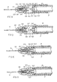
- FIGS. 10 to 15 are views similar to that of FIG. 8 but showing successive stages of plunger forward travel up to and including completion of drug dispensing and operation of the needle retraction mechanism;
- FIG. 16 is a perspective view of a syringe barrel and plunger and an adapter
- FIG. 17 is a cross-sectional view of a syringe, an adapter, and a sheath;
- FIG. 18 is a view similar to FIG. 16 with the adapter attached to the syringe;
- FIG. 19 is a perspective exploded view of a syringe, an adapter, and a sheath;
- FIG. 20 is an enlarged perspective view of the adapter and sheath of FIG. 19 ;
- FIG. 21 is a sectional view of an adapter and a sheath which are connected to each other;
- FIG. 22 is a perspective view of a syringe with an adapter secured thereto and an intravenous connector before it is connected to the adapter;
- FIG. 23 is a view similar to that of FIG. 22 with the intravenous connector connected to the adapter;
- FIG. 24 is a view similar to FIG. 23 with the plunger fully depressed.
- FIG. 25 is a perspective, exploded view, of a syringe and retractable needle assembly.
- FIG. 26 is a view of an assembled syringe and retractable needle assembly, before the plunger is depressed.
- the sheath 10 is formed, e.g. from metal or a plastics material, with a socket 11 at its rear end for engagement with the end cap E of a hypodermic syringe having a needle N, barrel B and plunger P.
- the sheath may engage with the syringe with push-on/pull-off friction fit.
- An annular seal 12 is provided on the end of the sheath 10 which abuts the forward face of an annular flange F at the rearward end of the cap E.
- the sheath 10 has a hollow interior 14 which accommodates the needle N of the syringe.
- the sheath 10 terminates in a pointed forward end 15 capable of penetrating the rubber cap of a vial or being inserted into an ampoule whose cap has been broken therefrom.
- the sheath is apertured at a location in close proximity to the pointed end 15 , the aperture being formed by an axially extending elongate slot. In the illustrated embodiment, two such slotted apertures 16 are provided on diametrically opposite sides of the sheath.
- a guard 17 in the form of a part cylindrical wall is formed integrally with the sheath 10 and is removable from the sheath at a frangible connection 18 .
- the guard protects the sheath and prevents its pointed end from damaging and thereby compromising the sterility of primary packaging in which the syringe is supplied.
- the slot 19 in the wall enables the guard to be broken away without damaging the sheath which can pass through the slot 19 during this operation.
- a filtering material depicted by reference numeral 20 is provided within the sheath at a location between the forward end of the needle and the apertures 16 so that only liquid that has passed through the filtering material is accessible by the needle during filling.
- particulate materials such as glass slivers, splinters or shards that may have inadvertantly contaminated the injection fluid are excluded by the filtering material thereby eliminating any risk of fine slivers of glass entering the syringe during filling thereof.
- the filter material may take various forms, e.g. it may be in the form of a fibrous extrusion or a porous plastic plug.
- the sheath is provided with needle-wiping means which, in the illustrated embodiment, is in the form of a thin web of material or membrane 22 , e.g. an elastomer such as a suitable silicone, extending across the interior of the sheath so that, when the latter is assembled to the syringe, the needle passes through the web.
- the web may be provided with a pre-formed hole through which the needle passes or the hole may be formed by the needle automatically during the act of pushing the sheath on to the syringe.
- the arrangement is such that the marginal edge around the hole in the web contacts the needle around its circumference so that, when the sheath is subsequently removed, the marginal edge cleans off any excess liquid adhering to the outside of the needle following the filling operation.
- the membrane 22 may be of an elastomeric material such as silicone rubber.
- the syringe is removed from its primary packaging and the barrel B of the syringe filled in known manner by retraction of the plunger P after insertion of the forward end of the sheath through the rubber cap of a vial or insertion of the forward end into an ampoule whose cap has been broken therefrom.
- the injection liquid passes through the filtering material before entry into the needle.
- the sheath 10 is then removed and discarded to enable administration of the injection in known manner. During sheath removal, the outside of the needle is automatically wiped clean.
- the needle-wiping means 40 may in one embodiment of the invention be in the form of a disc comprising a peripheral ring 42 , e.g. of O-section, and an integral central web 44 .
- the disc is assembled to the sheath by seating the O-ring firmly, preferably with a sealing engagement, in an annular groove 46 formed in the wall 48 of the sheath 10 .
- the disc comprises an elastomeric material.
- the interior volume within the sheath between the central web 44 and the tip of the sheath may be made airtight to allow suction to be developed.
- FIGS. 5 and 5A illustrate another form of needle-wiping disc 50 designed to effect a seal with the nose 58 of the barrel B.
- the disc 50 comprises a web 52 from one face of which an upstanding generally O-section ring 54 projects.
- the ring 54 seats in a groove 56 of the sheath 10 so that, on assembly of the sheath to the barrel, the ring 54 is engaged between the sheath and barrel to form an air-tight seal.
- the disc is fabricated from an elastomeric material and the web is sufficiently thin that it is readily pierced by, and seals around, the needle during assembly of the sheath to the barrel. In this instance, sealing is effected by the disc 50 at two locations, namely around the needle itself and also at the point of contact with the nose 58 of the barrel B.
- FIGS. 6 and 6A in addition to the seal between the sheath and the interior of the needle, there is also a one-way valve which ensures that the flow of fluid can only take place in one direction when the sheath is fitted to the syringe.
- FIG. 6 those parts in common with FIGS. 1 to 3 are depicted by the same reference numerals and will not be described further. As shown in FIG.
- a one-piece moulding 60 is located within the interior of the sheath and forms a one-way valved septum chamber 62 comprising a web 64 which extends across the cross-section of the sheath to form a seal which isolates the lower interior volume of the sheath extending between the web 64 and the tip 15 of the sheath from the upper interior volume extending between the web 64 and the nose of the barrel B.
- the moulding includes a generally cylindrical side wall 66 which nests within the interior of the sheath and a wall 68 which includes an enlargement 70 forming a valve member normally seats against and makes sealing engagement with the upper end of the passageway 72 extending through the projecting spike-like formation of the sheath 10 .
- the wall 68 only extends only partway across the diameter of the moulding in such a way that it can flex towards the wall 64 by flow of liquid through the spike-like formation of sheath 10 . In the absence of liquid ingress, the wall 68 biases the valve member 70 to its closed position in which it closes the upper end of the hollow spike-like formation.
- the needle N pierces the web 64 and penetrates into the septum chamber 62 (see FIG. 6 A).
- the syringe is operated to aspirate the liquid through the needle N so that the resulting suction effect draws the valve member 70 away from its seating 72 at the upper end of the spike-like formation to draw the liquid upwardly into the septum chamber 62 and then into the needle to fill the syringe.
- liquid drawn into the needle N in this way must first traverse the filter 20 and any glass shards or contaminants present may be excluded from passing into the septum chamber 62 and hence the syringe. Flow of liquid in the opposite direction is prevented since such flow will tend to cause the valve member 70 to make sealing contact with the seat 72 at the upper end of the spike-like formation and thereby block liquid flow.
- the sheath 10 may be removed from the syringe prior to using the syringe to administer an injection to the patient.
- the web 64 which by virtue of its resilient nature contracts around the needle, is drawn along the forward extremity of the needle thereby wiping any excess liquid from the exterior of the needle before it is used to inject a patient.
- the one-way valve ensures that the injection can only be administered after the sheath has been removed from the syringe thereby eliminating the possibility of an injection being administered while the sheath is still in place.
- the sheath is generally spike-shaped so that it can be used to penetrate or pierce the rubber cap of a vial directly.
- FIG. 7 illustrates an embodiment in which the sheath is of two-part construction comprising an adaptor section 80 which may incorporate the wiper and/or the filter and a separate auxiliary needle-carrying section 82 .
- the adaptor section 80 at its upper end 84 is adapted to be releasably engaged with the nose 86 of the syringe barrel B.
- it may be a simple push fit (in the direction X) on to the barrel nose 86 and, when so fitted, it may form a fluid-tight seal although this is not essential if the wiping membrane serves this purpose.
- the wiper membrane 64 is embodied in a one-piece moulding 60 of an elastomeric material which also incorporates a one-way valve 70 co-operating with seat 72 , the arrangement being such that when the sheath is fitted to the barrel, the needle N pierces the membrane 64 and communicates with the septum volume 62 (in the manner shown in FIG. 6 A).
- the membrane 64 serves the dual function of providing a seal around the needle N when the sheath is correctly assembled to the syringe and wiping the needle N on removal of the sheath from the syringe.
- the forward end 87 of the adaptor section 80 and the needle-carrying section 82 are designed to fit together with a sealing engagement, e.g. by means of a luer slip or luer lock fitting.
- the forward end 87 accommodates a plug 20 of filter material so that liquid entering the septum chamber 62 must first traverse the filter thereby excluding foreign matter such as glass shards that might be present when the syringe is filled from a glass ampoule.
- the needle 88 of section 82 is employed purely as a filling needle which is used to pierce the rubber cap of a vial for example, liquid being drawn into the syringe via the needle 88 , one-way valve 70 , septum chamber 62 and needle N by appropriate operation of the syringe plunger. After the filling operation has been completed, the section 82 is removed and discarded while the adaptor section 80 can be left in place until the syringe is used to administer the injection.
- the syringe may be of the type provided with a needle retraction mechanism whereby, after administration of the injection, the needle N is retracted from the projecting position illustrated to an inaccessible position so as to prevent needle stick injuries.
- a suitable needle retraction mechanism for use in the present invention is that disclosed in U.S. Pat. No. 5,782,804, the entire disclosure of which is incorporated herein by this reference.
- the barrel B of the syringe includes a mounting portion 98 for the needle N, having a through passage at the inner end of which is an upstanding annular wall 99 .
- the inner end of the needle N is axially captive with a hub 118 having an annular flange 119 which locates an O-ring 120 .
- the hub 118 provides a passageway for the needle N.
- a compression spring 128 surrounds the needle so as to bias the hub 118 and hence the needle rearwardly. When assembled, the spring 128 is in an almost fully compressed condition and is maintained in that condition by the O-ring 120 which is compressed between annular wall portion 132 and the hub 118 .
- the O-ring 120 is prevented from movement in the rearward direction by a crown 136 which is, itself, blocked from rearward movement by projections 137 (see FIG. 9 ).
- the crown 136 comprises a ring 138 provided with a pair of rearwardly directed extensions 140 of arcuate configuration, the dimension of the ring 138 and the spacing of the extensions being sufficient to allow the needle hub to pass during the needle retraction phase as described below.
- the extensions 140 project into the interior of the barrel when the syringe is in its pre-use condition shown in FIG. 8 . As seen in FIG. 8 , there is an annular space 135 forwardly of the O-ring 120 .
- the plunger P of the syringe is hollow having its rear end (not shown in FIGS. 8 to 15 ) closed by a cap.
- the forward end of the plunger P is provided with an insert 142 which engages firmly in the plunger and is encircled by seal 143 which contacts the internal surface of the barrel B.
- the insert 142 constitutes a “bursting disc” device and includes an annular rim portion 150 and a central generally frusto-conical formation or cone 152 which is connected to the rim portion 150 in a frangible fashion, e.g. by a thin web of material which can be ruptured or broken away when the central cone 152 is stressed axially relative to the rim portion.
- the syringe In operation, the syringe is charged with liquid via the sheath 10 as described previously to achieve its ready-for-use condition in which the plunger P is drawn back rearwardly relative to the barrel B. After removal of the sheath 10 (not shown in FIGS. 8 to 15 ), the plunger P is caused to move forwardly relative to the barrel (i.e. to the left as seen in FIGS. 8 to 15 ) and the advancing plunger is effective to expel liquid through the needle N.
- FIG. 10 shows the positions of the parts after the plunger P has been advanced sufficiently to bring the leading end face of the rim portion 150 into abutment with the trailing ends of the extensions 140 .
- Further forward travel of the plunger P is effective to push the crown 136 forwardly (by virtue of contact between the rim portion 150 and the extensions 140 ), which forward movement is transmitted to the needle hub 118 through the O-ring 120 thereby taking up the small amount of axial play initially present between the flange 119 and the trailing end of the annular wall 99 and terminating any further forward movement of the needle hub.
- With hub 119 blocked by wall 99 continued forward movement of the plunger P is then effective to begin displacing the O-ring 120 as shown in FIG. 12 , i.e. the O-ring then begins to expand over the flange 119 of the hub.
- the foward end of the cone 152 eventually comes into contact with the rear face of the needle hub 118 .
- the O-ring 120 is still effective to maintain a seal and drug continues to be expelled from the barrel via a slot 154 in the forward end face of the cone 152 .
- continued pressure applied to the plunger in the forward direction is effective to stress the thin web interconnecting the cone 152 and the rim portion 150 and deform the web towards its breaking point.
- the arrangement is such that web integrity is maintained until such time as O-ring 120 has been fully pushed over the flange 119 and onto the annular wall 99 (see FIG.
- the needle N need only be exposed during the administration of the intended injection. At all other times, the needle may be either sheathed with the aid of sheath or inaccessible as a result of being retracted into the plunger (and hence the barrel).
- FIGS. 16-23 there is shown an alternative embodiment of the invention.
- This embodiment comprises a needle-free injection system.
- an adapter 166 is provided for use with a barrel B and with a filling spike 208 to draw medication into the barrel and to thereafter inject it into a patient by way of an intravenous fitting 226 as best seen in FIGS. 22 and 23 .
- barrel B is provided with a projection 160 and external threads 162 , such as for instance, for use with a luer slip or luer lock fitting.
- adapter 166 is provided with internal threads 164 for engaging external threads 162 of barrel B.
- Adapter 166 includes external fluting 167 whereby adapter 166 can be more easily gripped for securement to barrel B.
- Adapter 166 also includes an internal extension 171 which defines a hollow space 173 together with the outside wall of adapter 166 .
- Windows 170 are provided by the use of side-cores in molding adapter 176 to enable the formation of internal threads on the adapter.
- Projection 168 and the outside wall of adapter 166 also form a hollow space 175 .
- the inside surface of the outside wall of adapter 166 is provided with internal threads 172 .
- adapter 166 can be threadedly engaged with barrel B by engagement of internal threads 164 with external threads 162 of barrel B. Such threads may provide a luer lock or other suitable threaded engagement.
- Threads 172 permit a filling spike 208 to be threadedly attached to adapter 166 for filling barrel B.
- an intravenous adapter 226 can be threadedly connected to internal threads 172 of adapter 166 when it is desired to inject medicine from barrel B into a patient.
- projection 168 has an aperture 178 and is hollow and defines a hollow interior passageway 176 which extends completely through adapter 166 .
- fluid can be drawn into barrel B through passageway 176 when filling spike 208 is connected to adapter 166 , as shown in FIG. 21 or alternatively can be expelled through passageway 176 through an intravenous fitting 226 , as further explained hereinafter.
- filling spike 208 includes a hollow sheath 210 .
- Sheath 210 includes a pointed end 215 and one or more filling slots 216 in pointed end 215 .
- Filling spike 208 further includes a central portion 219 whereby filling spike 208 can be gripped and manipulated.
- Windows 212 are provided as side-cores in the molding process to maintain a constant material thickness.
- a guard 217 is provided which is connected to central portion 219 by means of a frangible connection 218 . Guard 217 can be removed from filling spike 208 by fracturing frangible connection 218 .
- An extension 213 is also connected to central portion 219 and includes external threads 214 , whereby filling spike 208 can be threadedly connected to adapter 166 .
- Threads 214 and 172 could define a luer type fitting.
- filling spike 208 may be connected by threaded engagement to adapter 166 , which in turn can be secured to barrel B as shown in FIG. 18 .
- Guard 217 would be removed by fracturing frangible connection 218 whereby sheath 210 is exposed and can be inserted into a container in the manner heretofore described.
- the filling operation of barrel B would include applying pressure to thumb pad T whereby plunger P is moved into barrel B, before sheath 10 is inserted into a vial (not shown) which includes the medicine.
- the syringe can be manipulated by having a user place two fingers below grip G of barrel B whereby pressure can be applied to thumb pad T.
- Filling spike 208 is now inserted into the vial or other container which contains the medicine.
- the plunger is then moved backward by having a person apply a pulling force on thumb pad T and plunger P.
- filling spike 208 can be removed by disengaging threads 214 from threads 172 .
- an intravenous fitting 226 and associated tubing 228 can be connected to adapter 166 by threaded engagement of threads 229 with internal threads 172 as shown in FIGS. 22 and 23 .
- the other end of tubing 228 is connected to a patient by conventional means such as an I.V. catheter or other I.V. access system.
- the medicine in barrel B can then be injected through tubing 228 and into the patient by applying pressure to thumb pad T and forcing piston P into barrel B, thereby expelling the medicine from the barrel, through adapter 166 , intravenous fitting 226 , tubing 228 , and into the patient.
- adapter 166 may be removed from barrel B, once medicine has been drawn into the barrel.
- a retractable needle assembly 230 can then be secured to rejection 160 of barrel B, as shown in FIG. 26 , so that plunger P can be depressed as described hereintobefore and the medicine can be injected into a patient through needle N.
- threads 232 would have advantageously be such that needle assembly 230 cannot be removed from barrel B, once it has been attached. In that arrangement, once the medicine has been ejected from barrel B, the automatic retraction mechanism described hereintofore will cause needle N to be retracted into the plunger while retractable needle assembly 230 cannot be thereafter removed from the barrel for safe disposal of needle N.
Abstract
A syringe assembly including an adapter, a sheath and filling spike for connecting to said adapter and an intravenous connector for intravenously administering medicine to a patient. The barrel may be connected to the adapter and the filling spike for filling the barrel with medicine. The medicine can then be injected into a patient through either the needleless intravenous injection system or through a retractable needle assembly.
Description
This is a continuation-in-part of U.S. patent application Ser. No. 09/563,268 entitled “Needle Sheath”, filed May 3, 2000 now U.S. Pat. No. 6,524,278, which is a continuation of PCT/GB99/02175, filed Jul. 7, 1999.
This invention concerns a sheath for the needle of a hypodermic syringe.
Hypodermic syringe assemblies are usually provided with a protective sheath covering the needle for its protection until the syringe is required for use.
It is a common, though by no means universal, practice to change the needle of a syringe after filling and before administration of the injection because of a perception that the original needle may become blunted, bent or subjected to loss of needle lubricant during the filling operation, for example by insertion through the rubber cap of the vial, contaminated with a foreign substance, for example latex from such a cap or rendered unsterile, or to suit filling requirements for rapid filling of the syringe by using a large bore filling needle.
In the case of syringes with provision for retraction of the needle after use as disclosed for instance in our prior U.S. Pat. No. 5,782,804, the needle assembly tends to be specially designed for this purpose and it is not therefore practical to contemplate changing needles after filling the syringe and before administering the injection.
There are also concerns over the risks of drawing in fragments or slivers of material, e.g. glass, when the syringe is filled from for example an ampoule following breaking of a glass or other cap of the ampoule. Moreover, if the same needle is used to fill the syringe and also administer the medication, some injection fluid may be present on the outside of the needle which may be undesirable since some substances for injection can be irritating to the skin.
Further, it is often desirable to have the ability to administer an injection by either a retractable needle or by means of an intravenous means.
These matters are addressed by various aspects of the present invention. The invention has particular, but not necessarily exclusive, application to the type of syringe which incorporates a needle retraction mechanism and is thereby not readily amenable to the possibility of needle change between syringe filling and admistration of the injection. Further, an arrangement is disclosed including a filling spike and an adapter for intravenous injection.
According to one aspect of the present invention there is provided a hypodermic syringe having a barrel, a hollow fluid dispensing needle which projects from the barrel, means for retracting the needle after use from the projecting position to a retracted, inaccessible position, and a sheath which is removably engageable with the syringe to sheath the needle and provide an interior zone for communication with the internal bore of the needle, the sheath being apertured to admit liquid to said zone whereby liquid drawn through the needle into the syringe first passes into said zone.
The sheath may be shaped or adapted so as to be capable of penetrating the rubber cap of a vial or the like. To this end, it may be provided with a pointed end or a separate needle. In this way, the sheath may be used as a needle during filling of the syringe thereby avoiding any risk of compromising the needle proper as discussed above through having to use the needle proper to pierce a rubber cap for instance.
When used with a syringe having needle retraction means, the needle need only be exposed during the time that it is actually in use for the administration of an injection. At all other times, including filling of the syringe, the needle may be effectively inaccessible thereby considerably reducing the risk of needle stick injuries since the sheath need not be particularly sharp as it is only used for filling the syringe.
The sheath together with its pointed end or filling needle may be used together with an adapter whereby, after filling of the syringe by means of the pointed end of the sheath, the adapter can be directly connected to an intravenous injection system. Alternatively, a retractable needle may then be used to inject the medicine into a patient.
According to a second aspect of the present invention there is provided a sheath which sealably connects over the needle of a hypodermic syringe and is optionally shaped or adapated to penetrate the rubber cap of a vial or the like, the sheath being apertured to allow the ingress of liquid to an interior zone thereof whereby liquid drawn through the needle into the syringe first passes into said zone, filter means being incorporated in the sheath to exclude the entry of particulate material into said zone.
According to a further aspect of the present invention there is provided a sheath which sealably connects over the needle of a hypodermic syringe and is optionally shaped or adapated to penetrate the rubber cap of a vial or the like, the sheath being apertured to allow the ingress of liquid to an interior zone thereof whereby liquid drawn through the needle into the syringe first passes into said zone, needle-wiping means being incorporated in the sheath and arranged so that removal of the sheath automatically wipes the needle to remove any excess liquid on the outside thereof.
According to a still further aspect of the present invention, there is provided a sheath and an adapter. The adapter can be directly connected to the barrel of the syringe, and the sheath can be attached thereto. The pointed portion of the sheath can be used to fill the syringe. Thereafter the sheath can be removed and the adapter can be directly connected to a needleless I.V. access system. Alternatively, the adapter may be removed and a retractable needle assembly can be connected to the barrel to administer the medicine to a patient.
The sheath may, if desired, incorporate both filter means and needle-wiping means.
The filter means may be be take take various forms—for example the filter means may be composed of fibrous material or it may comprise a sintered plastics material. Examples of suitable materials include hydrophilic and hydrophobic materials. The plastics materials employed may for instance be selected from the following, including combinations thereof: nylon, polyurethane, polyester, polyolefin, polyethylene, PTFE, acetal, acrylonitrile butadiene styrene and styrene acrylonitrile. Most of these materials can be processed in a number of ways with the exception of PTFE which will generally be sintered. The other materials can be moulded with a foaming agent to give an open cell foam with controllable porosity or made into a non-woven fibrous mat by using a binder compound. Suitable filter materials for use in the present invention are obtainable from for example GVS Srl of Bologna, Italy and Filtertek BV of Limerick, Eire.
The needle-wiping means is conveniently in the form of a thin web or membrane through which the needle extends in use so that when the sheath is removed from the sheath, the marginal edge of the web or membrane surrounding the needle is drawn along the outside the needle thereby wiping the same. Preferably the web or membrane is composed of a resilient material and tends to contract around the needle by virtue of its resilient nature. Suitable materials for the membrane or web include elastomers such as silicones or silicone-based materials.
The sheath may have a pointed end to facilitate penetration into a vessel, e.g. via a rubber seal or cap provided on the vessel.
The sheath may have at least one aperture through its wall above the pointed end and/or it may have an aperture at its pointed end.
The sheath may be protected before use by a removable guard which is conveniently in the form of a part cylindrical wall.
The guard may be integral with the sheath and removable at one or more frangible connections.
The sheath may be removably attachable to the syringe through a push-on/pull-off friction fit or snap fit or through a threaded connection or a bayonet-type connection.
The sheath may be formed from a metal or a plastics material.
The invention will be further apparent from the following description with reference to the several figures of the accompanying drawings which show, by way of example only, several forms of sheath embodying same. In the drawings:
Corresponding reference characters indicate corresponding parts throughout the several views. The exemplification set out herein illustrates preferred embodiments of the invention, in one form, and such exemplification is not to be construed as limiting the scope of the invention in any manner.
Referring now to FIGS. 1 to 3 of the drawings, the sheath 10 is formed, e.g. from metal or a plastics material, with a socket 11 at its rear end for engagement with the end cap E of a hypodermic syringe having a needle N, barrel B and plunger P. The sheath may engage with the syringe with push-on/pull-off friction fit. An annular seal 12 is provided on the end of the sheath 10 which abuts the forward face of an annular flange F at the rearward end of the cap E.
The sheath 10 has a hollow interior 14 which accommodates the needle N of the syringe. The sheath 10 terminates in a pointed forward end 15 capable of penetrating the rubber cap of a vial or being inserted into an ampoule whose cap has been broken therefrom. The sheath is apertured at a location in close proximity to the pointed end 15, the aperture being formed by an axially extending elongate slot. In the illustrated embodiment, two such slotted apertures 16 are provided on diametrically opposite sides of the sheath.
A guard 17 in the form of a part cylindrical wall is formed integrally with the sheath 10 and is removable from the sheath at a frangible connection 18. The guard protects the sheath and prevents its pointed end from damaging and thereby compromising the sterility of primary packaging in which the syringe is supplied. The slot 19 in the wall enables the guard to be broken away without damaging the sheath which can pass through the slot 19 during this operation.
A filtering material depicted by reference numeral 20 is provided within the sheath at a location between the forward end of the needle and the apertures 16 so that only liquid that has passed through the filtering material is accessible by the needle during filling. In this way, particulate materials, such as glass slivers, splinters or shards that may have inadvertantly contaminated the injection fluid are excluded by the filtering material thereby eliminating any risk of fine slivers of glass entering the syringe during filling thereof. The filter material may take various forms, e.g. it may be in the form of a fibrous extrusion or a porous plastic plug.
At a suitable location, the sheath is provided with needle-wiping means which, in the illustrated embodiment, is in the form of a thin web of material or membrane 22, e.g. an elastomer such as a suitable silicone, extending across the interior of the sheath so that, when the latter is assembled to the syringe, the needle passes through the web. The web may be provided with a pre-formed hole through which the needle passes or the hole may be formed by the needle automatically during the act of pushing the sheath on to the syringe. In either case, the arrangement is such that the marginal edge around the hole in the web contacts the needle around its circumference so that, when the sheath is subsequently removed, the marginal edge cleans off any excess liquid adhering to the outside of the needle following the filling operation. The membrane 22 may be of an elastomeric material such as silicone rubber.
In use, the syringe is removed from its primary packaging and the barrel B of the syringe filled in known manner by retraction of the plunger P after insertion of the forward end of the sheath through the rubber cap of a vial or insertion of the forward end into an ampoule whose cap has been broken therefrom. During filling, the injection liquid passes through the filtering material before entry into the needle. The sheath 10 is then removed and discarded to enable administration of the injection in known manner. During sheath removal, the outside of the needle is automatically wiped clean.
It sometimes happens that medical staff use a filling needle of larger bore than the injection needle for the purposes of filling the syringe—particularly when the bore of the injection needle is particularly fine. The possibility of removing the sheath 10 and original needle before replacing the sheath 10 and using it as a filling needle should not be overlooked.
Referring now to FIG. 4 , the needle-wiping means 40 may in one embodiment of the invention be in the form of a disc comprising a peripheral ring 42, e.g. of O-section, and an integral central web 44. The disc is assembled to the sheath by seating the O-ring firmly, preferably with a sealing engagement, in an annular groove 46 formed in the wall 48 of the sheath 10. Typically the disc comprises an elastomeric material. When the sheath is assembled to the syringe, the needle will penetrate the central web which, by virtue of its elastomeric nature, will seal around the outer periphery of the needle. The web may be initially imperforate or it may be preformed with an aperture through which the needle passes. In this way, when the tip of the sheath is inserted into a liquid to be drawn into the syringe, the interior volume within the sheath between the central web 44 and the tip of the sheath may be made airtight to allow suction to be developed.
In the embodiment of FIGS. 6 and 6A , in addition to the seal between the sheath and the interior of the needle, there is also a one-way valve which ensures that the flow of fluid can only take place in one direction when the sheath is fitted to the syringe. In FIG. 6 , those parts in common with FIGS. 1 to 3 are depicted by the same reference numerals and will not be described further. As shown in FIG. 6 , a one-piece moulding 60 is located within the interior of the sheath and forms a one-way valved septum chamber 62 comprising a web 64 which extends across the cross-section of the sheath to form a seal which isolates the lower interior volume of the sheath extending between the web 64 and the tip 15 of the sheath from the upper interior volume extending between the web 64 and the nose of the barrel B. The moulding includes a generally cylindrical side wall 66 which nests within the interior of the sheath and a wall 68 which includes an enlargement 70 forming a valve member normally seats against and makes sealing engagement with the upper end of the passageway 72 extending through the projecting spike-like formation of the sheath 10. The wall 68 only extends only partway across the diameter of the moulding in such a way that it can flex towards the wall 64 by flow of liquid through the spike-like formation of sheath 10. In the absence of liquid ingress, the wall 68 biases the valve member 70 to its closed position in which it closes the upper end of the hollow spike-like formation.
In use, when the sheath has been assembled to the syringe, the needle N pierces the web 64 and penetrates into the septum chamber 62 (see FIG. 6A). When the cylindrical guard 17 has been removed and the tip of sheath is immersed in a liquid, the syringe is operated to aspirate the liquid through the needle N so that the resulting suction effect draws the valve member 70 away from its seating 72 at the upper end of the spike-like formation to draw the liquid upwardly into the septum chamber 62 and then into the needle to fill the syringe. Also, liquid drawn into the needle N in this way must first traverse the filter 20 and any glass shards or contaminants present may be excluded from passing into the septum chamber 62 and hence the syringe. Flow of liquid in the opposite direction is prevented since such flow will tend to cause the valve member 70 to make sealing contact with the seat 72 at the upper end of the spike-like formation and thereby block liquid flow.
Subsequently the sheath 10 may be removed from the syringe prior to using the syringe to administer an injection to the patient. In the course of removing the sheath the web 64, which by virtue of its resilient nature contracts around the needle, is drawn along the forward extremity of the needle thereby wiping any excess liquid from the exterior of the needle before it is used to inject a patient. It will be observed that the one-way valve ensures that the injection can only be administered after the sheath has been removed from the syringe thereby eliminating the possibility of an injection being administered while the sheath is still in place.
In the embodiments thus far described, the sheath is generally spike-shaped so that it can be used to penetrate or pierce the rubber cap of a vial directly. FIG. 7 illustrates an embodiment in which the sheath is of two-part construction comprising an adaptor section 80 which may incorporate the wiper and/or the filter and a separate auxiliary needle-carrying section 82. The adaptor section 80 at its upper end 84 is adapted to be releasably engaged with the nose 86 of the syringe barrel B. For example, it may be a simple push fit (in the direction X) on to the barrel nose 86 and, when so fitted, it may form a fluid-tight seal although this is not essential if the wiping membrane serves this purpose. As in the embodiment of FIGS. 6 and 6A , the wiper membrane 64 is embodied in a one-piece moulding 60 of an elastomeric material which also incorporates a one-way valve 70 co-operating with seat 72, the arrangement being such that when the sheath is fitted to the barrel, the needle N pierces the membrane 64 and communicates with the septum volume 62 (in the manner shown in FIG. 6A). The membrane 64 serves the dual function of providing a seal around the needle N when the sheath is correctly assembled to the syringe and wiping the needle N on removal of the sheath from the syringe.
The forward end 87 of the adaptor section 80 and the needle-carrying section 82 are designed to fit together with a sealing engagement, e.g. by means of a luer slip or luer lock fitting. The forward end 87 accommodates a plug 20 of filter material so that liquid entering the septum chamber 62 must first traverse the filter thereby excluding foreign matter such as glass shards that might be present when the syringe is filled from a glass ampoule. The needle 88 of section 82 is employed purely as a filling needle which is used to pierce the rubber cap of a vial for example, liquid being drawn into the syringe via the needle 88, one-way valve 70, septum chamber 62 and needle N by appropriate operation of the syringe plunger. After the filling operation has been completed, the section 82 is removed and discarded while the adaptor section 80 can be left in place until the syringe is used to administer the injection.
In each of the embodiments described above, the syringe may be of the type provided with a needle retraction mechanism whereby, after administration of the injection, the needle N is retracted from the projecting position illustrated to an inaccessible position so as to prevent needle stick injuries. A suitable needle retraction mechanism for use in the present invention is that disclosed in U.S. Pat. No. 5,782,804, the entire disclosure of which is incorporated herein by this reference.
One embodiment of the needle retraction mechanism will now be described with reference to FIGS. 8 to 15. The barrel B of the syringe includes a mounting portion 98 for the needle N, having a through passage at the inner end of which is an upstanding annular wall 99. The inner end of the needle N is axially captive with a hub 118 having an annular flange 119 which locates an O-ring 120. The hub 118 provides a passageway for the needle N. A compression spring 128 surrounds the needle so as to bias the hub 118 and hence the needle rearwardly. When assembled, the spring 128 is in an almost fully compressed condition and is maintained in that condition by the O-ring 120 which is compressed between annular wall portion 132 and the hub 118. The O-ring 120 is prevented from movement in the rearward direction by a crown 136 which is, itself, blocked from rearward movement by projections 137 (see FIG. 9). The crown 136 comprises a ring 138 provided with a pair of rearwardly directed extensions 140 of arcuate configuration, the dimension of the ring 138 and the spacing of the extensions being sufficient to allow the needle hub to pass during the needle retraction phase as described below. The extensions 140 project into the interior of the barrel when the syringe is in its pre-use condition shown in FIG. 8. As seen in FIG. 8 , there is an annular space 135 forwardly of the O-ring 120.
The plunger P of the syringe is hollow having its rear end (not shown in FIGS. 8 to 15) closed by a cap. The forward end of the plunger P is provided with an insert 142 which engages firmly in the plunger and is encircled by seal 143 which contacts the internal surface of the barrel B. The insert 142 constitutes a “bursting disc” device and includes an annular rim portion 150 and a central generally frusto-conical formation or cone 152 which is connected to the rim portion 150 in a frangible fashion, e.g. by a thin web of material which can be ruptured or broken away when the central cone 152 is stressed axially relative to the rim portion. In operation, the syringe is charged with liquid via the sheath 10 as described previously to achieve its ready-for-use condition in which the plunger P is drawn back rearwardly relative to the barrel B. After removal of the sheath 10 (not shown in FIGS. 8 to 15), the plunger P is caused to move forwardly relative to the barrel (i.e. to the left as seen in FIGS. 8 to 15) and the advancing plunger is effective to expel liquid through the needle N.
As shown in FIG. 13 , the foward end of the cone 152 eventually comes into contact with the rear face of the needle hub 118. At this stage, the O-ring 120 is still effective to maintain a seal and drug continues to be expelled from the barrel via a slot 154 in the forward end face of the cone 152. Once the cone 152 has come into contact with the needle hub 118, continued pressure applied to the plunger in the forward direction is effective to stress the thin web interconnecting the cone 152 and the rim portion 150 and deform the web towards its breaking point. Before the web breaks however, the arrangement is such that web integrity is maintained until such time as O-ring 120 has been fully pushed over the flange 119 and onto the annular wall 99 (see FIG. 14 ) so as to disable the coupling action afforded by the O-ring between the needle hub and the crown. The procedure is completed by breakage of the thin web thus allowing the spring 128 to expand and drive the needle hub and connected needle N rearwardly together with the broken away formation 152 into the interior of the plunger thereby rendering the needle inaccessibly concealed wholly within the syringe as shown in FIG. 15.
It will be seen that the needle N need only be exposed during the administration of the intended injection. At all other times, the needle may be either sheathed with the aid of sheath or inaccessible as a result of being retracted into the plunger (and hence the barrel).
Referring now to FIGS. 16-23 , there is shown an alternative embodiment of the invention. This embodiment comprises a needle-free injection system. In this embodiment, as best seen in FIGS. 16 and 17 , an adapter 166 is provided for use with a barrel B and with a filling spike 208 to draw medication into the barrel and to thereafter inject it into a patient by way of an intravenous fitting 226 as best seen in FIGS. 22 and 23 .
More particularly, barrel B is provided with a projection 160 and external threads 162, such as for instance, for use with a luer slip or luer lock fitting. Further, adapter 166 is provided with internal threads 164 for engaging external threads 162 of barrel B. Adapter 166 includes external fluting 167 whereby adapter 166 can be more easily gripped for securement to barrel B. Adapter 166 also includes an internal extension 171 which defines a hollow space 173 together with the outside wall of adapter 166. Windows 170 are provided by the use of side-cores in molding adapter 176 to enable the formation of internal threads on the adapter.
Referring further to FIGS. 17 and 19-21, filling spike 208 includes a hollow sheath 210. Sheath 210 includes a pointed end 215 and one or more filling slots 216 in pointed end 215. Filling spike 208 further includes a central portion 219 whereby filling spike 208 can be gripped and manipulated. Windows 212 are provided as side-cores in the molding process to maintain a constant material thickness. Additionally, a guard 217 is provided which is connected to central portion 219 by means of a frangible connection 218. Guard 217 can be removed from filling spike 208 by fracturing frangible connection 218. An extension 213 is also connected to central portion 219 and includes external threads 214, whereby filling spike 208 can be threadedly connected to adapter 166. Threads 214 and 172 could define a luer type fitting. As can be seen in FIG. 21 , filling spike 208 may be connected by threaded engagement to adapter 166, which in turn can be secured to barrel B as shown in FIG. 18. Thus, in this configuration the syringe is ready to be filled with medicine. Guard 217 would be removed by fracturing frangible connection 218 whereby sheath 210 is exposed and can be inserted into a container in the manner heretofore described.
The filling operation of barrel B would include applying pressure to thumb pad T whereby plunger P is moved into barrel B, before sheath 10 is inserted into a vial (not shown) which includes the medicine. The syringe can be manipulated by having a user place two fingers below grip G of barrel B whereby pressure can be applied to thumb pad T. Filling spike 208 is now inserted into the vial or other container which contains the medicine. The plunger is then moved backward by having a person apply a pulling force on thumb pad T and plunger P. Once barrel B has been filled with medicine, filling spike 208 can be removed by disengaging threads 214 from threads 172. Thereafter, an intravenous fitting 226 and associated tubing 228 can be connected to adapter 166 by threaded engagement of threads 229 with internal threads 172 as shown in FIGS. 22 and 23 . The other end of tubing 228 is connected to a patient by conventional means such as an I.V. catheter or other I.V. access system. The medicine in barrel B can then be injected through tubing 228 and into the patient by applying pressure to thumb pad T and forcing piston P into barrel B, thereby expelling the medicine from the barrel, through adapter 166, intravenous fitting 226, tubing 228, and into the patient.
Referring now to FIGS. 25 and 26 , it should be noted that, rather than injecting medicine through a needleless injection system as shown in FIG. 24 , adapter 166 may be removed from barrel B, once medicine has been drawn into the barrel. A retractable needle assembly 230 can then be secured to rejection 160 of barrel B, as shown in FIG. 26 , so that plunger P can be depressed as described hereintobefore and the medicine can be injected into a patient through needle N. It should also be noted that threads 232 would have advantageously be such that needle assembly 230 cannot be removed from barrel B, once it has been attached. In that arrangement, once the medicine has been ejected from barrel B, the automatic retraction mechanism described hereintofore will cause needle N to be retracted into the plunger while retractable needle assembly 230 cannot be thereafter removed from the barrel for safe disposal of needle N.
While this invention has been described as having a preferred design, the present invention can be further modified within the spirit and scope of this disclosure. This application is therefore intended to cover any variations, uses, or adaptations of the invention using its general principles. Further, this application is intended to cover such departures from the present disclosure as come within known or customary practice in the art to which this invention pertains and which fall within the limits of the appended claims.
Claims (12)
1. A syringe for injecting medicine into an intravenous connector, said syringe comprising:
a barrel;
a plunger operatively connected with said barrel;
an adapter connected to said barrel; and
a filling spike engageable with said adapter to fill said barrel with medicine, said adapter disengageable from said filling spike and engageable with said intravenous connector whereby medicine may be ejected from said barrel and into a patient through said intravenous connector.
2. The syringe according to claim 1 wherein said adapter is threadedly engaged with said adapter.
3. The syringe of claim 1 wherein said adapter includes a connector portion which comprises a luer fitting.
4. The syringe according to claim 1 wherein said filling spike includes a guard and a sheath, said sheath frangibly connected to said sheath.
5. The syringe according to claim 4 wherein said sheath includes a pointed end for penetrating a membrane of a medicine vial.
6. A syringe comprising:
a barrel having a connector;
a plunger operatively connected with said barrel;
a retractable needle assembly;
a filling spike;
an adapter, said barrel selectively connectable to said filling spike and said adapter for filling said syringe with medicine, to said retractable needle assembly for administering medicine to a patient, and to said adapter and an intravenous connector for intravenously administering medicine to a patient.
7. The syringe according to claim 6 wherein said barrel is lockingly connectable to said retractable needle assembly.
8. The syringe according to claim 6 wherein said barrel is engageably connectable to said filling spike and said adapter.
9. The syringe according to claim 6 wherein said barrel is disengageably connectable to said adapter and an intravenous connector.
10. An adapter for use with a syringe, said adapter comprising an elongated conduit having a first end with first threads for engagement with a syringe, and a second end with second threads for selective engagement with one of a filling spike and an intravenous connector, whereby said adapter permits filling of said syringe with medicine by means of a said spike and administration of medicine to a patient by means of said intravenous connector.
11. The adapter of claim 10 wherein said first threads comprise a portion of a luer fitting.
12. The adapter of claim 10 wherein said second threads comprise a portion of a luer fitting.
Priority Applications (1)
| Application Number | Priority Date | Filing Date | Title |
|---|---|---|---|
| US10/349,378 US6958055B2 (en) | 1998-09-04 | 2003-01-20 | Retractable needle syringe including a sheath and an intravenous adapter |
Applications Claiming Priority (10)
| Application Number | Priority Date | Filing Date | Title |
|---|---|---|---|
| GB9819217.2 | 1998-09-04 | ||
| GBGB9819217.2A GB9819217D0 (en) | 1998-09-04 | 1998-09-04 | Sheath for the needle of a hypodermic syringe |
| GB9907274.6 | 1999-03-21 | ||
| GBGB9907274.6A GB9907274D0 (en) | 1999-03-31 | 1999-03-31 | Sheath for the needle of a hypodermic syringe |
| WOPCT/GB99/02175 | 1999-07-07 | ||
| PCT/GB1999/002175 WO2000013727A1 (en) | 1998-09-04 | 1999-07-07 | Sheath for the needle of a hypodermic syringe |
| GB0005086.4 | 2000-03-03 | ||
| GB0005086A GB2359754B (en) | 2000-03-03 | 2000-03-03 | Needle sheath |
| US09/563,268 US6524278B1 (en) | 1998-09-04 | 2000-05-03 | Needle sheath |
| US10/349,378 US6958055B2 (en) | 1998-09-04 | 2003-01-20 | Retractable needle syringe including a sheath and an intravenous adapter |
Related Parent Applications (1)
| Application Number | Title | Priority Date | Filing Date |
|---|---|---|---|
| US09/563,268 Continuation-In-Part US6524278B1 (en) | 1998-09-04 | 2000-05-03 | Needle sheath |
Publications (2)
| Publication Number | Publication Date |
|---|---|
| US20030236501A1 US20030236501A1 (en) | 2003-12-25 |
| US6958055B2 true US6958055B2 (en) | 2005-10-25 |
Family
ID=29783274
Family Applications (1)
| Application Number | Title | Priority Date | Filing Date |
|---|---|---|---|
| US10/349,378 Expired - Fee Related US6958055B2 (en) | 1998-09-04 | 2003-01-20 | Retractable needle syringe including a sheath and an intravenous adapter |
Country Status (1)
| Country | Link |
|---|---|
| US (1) | US6958055B2 (en) |
Cited By (53)
| Publication number | Priority date | Publication date | Assignee | Title |
|---|---|---|---|---|
| US20080097353A1 (en) * | 2006-10-23 | 2008-04-24 | Sue Carr | Filter needle |
| US7666166B1 (en) * | 2004-12-27 | 2010-02-23 | Blivic, Llc | Bloodless intravenous integrated catheter |
| US20100204675A1 (en) * | 2006-11-03 | 2010-08-12 | Kevin Woehr | Catheter assembly and components thereof |
| US7803132B2 (en) | 2004-10-14 | 2010-09-28 | Midland Medical Device Holdings, LLC | Safety medical syringe with retractable needle |
| US7846135B2 (en) | 2006-02-24 | 2010-12-07 | Midland Medical Holding LLC | Retractable needle syringe with needle trap |
| USD665497S1 (en) * | 2010-07-28 | 2012-08-14 | Owen Mumford Limited | Torque limiting needle cap |
| US8333735B2 (en) | 2002-07-04 | 2012-12-18 | B. Braun Melsungen Ag | Catheter insertion device |
| US8430804B2 (en) | 2008-01-07 | 2013-04-30 | Salutaris Medical Devices, Inc. | Methods and devices for minimally-invasive extraocular delivery of radiation to the posterior portion of the eye |
| US8486024B2 (en) | 2011-04-27 | 2013-07-16 | Covidien Lp | Safety IV catheter assemblies |
| USD691270S1 (en) | 2009-01-07 | 2013-10-08 | Salutaris Medical Devices, Inc. | Fixed-shape cannula for posterior delivery of radiation to an eye |
| USD691268S1 (en) | 2009-01-07 | 2013-10-08 | Salutaris Medical Devices, Inc. | Fixed-shape cannula for posterior delivery of radiation to eye |
| USD691269S1 (en) | 2009-01-07 | 2013-10-08 | Salutaris Medical Devices, Inc. | Fixed-shape cannula for posterior delivery of radiation to an eye |
| USD691267S1 (en) | 2009-01-07 | 2013-10-08 | Salutaris Medical Devices, Inc. | Fixed-shape cannula for posterior delivery of radiation to eye |
| US8602959B1 (en) | 2010-05-21 | 2013-12-10 | Robert Park | Methods and devices for delivery of radiation to the posterior portion of the eye |
| US8608632B1 (en) | 2009-07-03 | 2013-12-17 | Salutaris Medical Devices, Inc. | Methods and devices for minimally-invasive extraocular delivery of radiation and/or pharmaceutics to the posterior portion of the eye |
| US8628497B2 (en) | 2011-09-26 | 2014-01-14 | Covidien Lp | Safety catheter |
| US8715250B2 (en) | 2011-09-26 | 2014-05-06 | Covidien Lp | Safety catheter and needle assembly |
| US20140135706A1 (en) * | 2008-06-02 | 2014-05-15 | Sta-Med, Llc | Needle cover |
| US8834422B2 (en) | 2011-10-14 | 2014-09-16 | Covidien Lp | Vascular access assembly and safety device |
| US8939938B2 (en) | 2006-10-12 | 2015-01-27 | Covidien Lp | Needle tip protector |
| US9056201B1 (en) | 2008-01-07 | 2015-06-16 | Salutaris Medical Devices, Inc. | Methods and devices for minimally-invasive delivery of radiation to the eye |
| US20160067410A1 (en) * | 2013-05-17 | 2016-03-10 | Carrtech Llc | Filtering Needle Cap |
| US9522254B2 (en) | 2013-01-30 | 2016-12-20 | Vascular Pathways, Inc. | Systems and methods for venipuncture and catheter placement |
| US9526846B2 (en) | 2009-08-19 | 2016-12-27 | Safety Syringes, Inc. | Patient-contact activated needle stick safety device |
| US9616201B2 (en) | 2011-01-31 | 2017-04-11 | Vascular Pathways, Inc. | Intravenous catheter and insertion device with reduced blood spatter |
| US9675784B2 (en) | 2007-04-18 | 2017-06-13 | Vascular Pathways, Inc. | Intravenous catheter insertion and blood sample devices and method of use |
| US9694140B2 (en) | 2010-06-23 | 2017-07-04 | Sta-Med, Llc | Automatic-locking safety needle covers and methods of use and manufacture |
| US9848810B2 (en) | 2011-05-31 | 2017-12-26 | Sta-Med, Llc | Blood collection safety devices and methods of use and manufacture |
| US9861792B2 (en) | 2011-02-25 | 2018-01-09 | C. R. Bard, Inc. | Medical component insertion device including a retractable needle |
| USD808529S1 (en) | 2016-08-31 | 2018-01-23 | Salutaris Medical Devices, Inc. | Holder for a brachytherapy device |
| US9873001B2 (en) | 2008-01-07 | 2018-01-23 | Salutaris Medical Devices, Inc. | Methods and devices for minimally-invasive delivery of radiation to the eye |
| USD808528S1 (en) | 2016-08-31 | 2018-01-23 | Salutaris Medical Devices, Inc. | Holder for a brachytherapy device |
| US9872971B2 (en) | 2010-05-14 | 2018-01-23 | C. R. Bard, Inc. | Guidewire extension system for a catheter placement device |
| USD814637S1 (en) | 2016-05-11 | 2018-04-03 | Salutaris Medical Devices, Inc. | Brachytherapy device |
| USD814638S1 (en) | 2016-05-11 | 2018-04-03 | Salutaris Medical Devices, Inc. | Brachytherapy device |
| USD815285S1 (en) | 2016-05-11 | 2018-04-10 | Salutaris Medical Devices, Inc. | Brachytherapy device |
| US9950139B2 (en) | 2010-05-14 | 2018-04-24 | C. R. Bard, Inc. | Catheter placement device including guidewire and catheter control elements |
| US10022558B1 (en) | 2008-01-07 | 2018-07-17 | Salutaris Medical Devices, Inc. | Methods and devices for minimally-invasive delivery of radiation to the eye |
| US10159788B2 (en) | 2013-05-01 | 2018-12-25 | Bayer Healthcare Llc | Attachment device for medical fluid container |
| US10220191B2 (en) | 2005-07-06 | 2019-03-05 | Vascular Pathways, Inc. | Intravenous catheter insertion device and method of use |
| US10232146B2 (en) | 2014-09-05 | 2019-03-19 | C. R. Bard, Inc. | Catheter insertion device including retractable needle |
| US10384039B2 (en) | 2010-05-14 | 2019-08-20 | C. R. Bard, Inc. | Catheter insertion device including top-mounted advancement components |
| US10493262B2 (en) | 2016-09-12 | 2019-12-03 | C. R. Bard, Inc. | Blood control for a catheter insertion device |
| USD903100S1 (en) | 2015-05-01 | 2020-11-24 | C. R. Bard, Inc. | Catheter placement device |
| USD903101S1 (en) | 2011-05-13 | 2020-11-24 | C. R. Bard, Inc. | Catheter |
| US11000678B2 (en) | 2010-05-14 | 2021-05-11 | C. R. Bard, Inc. | Catheter placement device and method |
| USD921884S1 (en) | 2018-07-27 | 2021-06-08 | Bard Access Systems, Inc. | Catheter insertion device |
| US11040176B2 (en) | 2015-05-15 | 2021-06-22 | C. R. Bard, Inc. | Catheter placement device including an extensible needle safety component |
| US11389626B2 (en) | 2018-03-07 | 2022-07-19 | Bard Access Systems, Inc. | Guidewire advancement and blood flashback systems for a medical device insertion system |
| US11400260B2 (en) | 2017-03-01 | 2022-08-02 | C. R. Bard, Inc. | Catheter insertion device |
| US11559665B2 (en) | 2019-08-19 | 2023-01-24 | Becton, Dickinson And Company | Midline catheter placement device |
| US11857768B1 (en) | 2022-10-01 | 2024-01-02 | CARRTECH Corp. | Filtering needle assembly with seal plug |
| US11925779B2 (en) | 2010-05-14 | 2024-03-12 | C. R. Bard, Inc. | Catheter insertion device including top-mounted advancement components |
Families Citing this family (30)
| Publication number | Priority date | Publication date | Assignee | Title |
|---|---|---|---|---|
| US10709850B2 (en) * | 2018-06-15 | 2020-07-14 | James T. Doubet | Syringe adapter for medication |
| US11097058B2 (en) | 2018-06-15 | 2021-08-24 | James T. Doubet | Syringe adapter for medication |
| US11337894B2 (en) | 2018-06-15 | 2022-05-24 | James T. Doubet | Syringe adapter for animal medication |
| US11090444B2 (en) | 2018-06-15 | 2021-08-17 | James T. Doubet | Syringe adapter for medication |
| KR20060009281A (en) * | 2003-05-01 | 2006-01-31 | 엔엠티 그룹 피엘씨 | Syringe system |
| US20050070854A1 (en) * | 2003-09-25 | 2005-03-31 | Wright Alastair Douglas | Syringe |
| US8002745B2 (en) * | 2004-01-28 | 2011-08-23 | Unitract Syringe Pty Ltd. | Retractable syringe with plunger disabling system |
| TWI256900B (en) | 2004-04-30 | 2006-06-21 | Ming-Jeng Shiu | Syringe with withdrawal force |
| US7465294B1 (en) * | 2004-05-19 | 2008-12-16 | Roman Vladimirsky | Retractable hypodermic needle |
| EP1625865B1 (en) | 2004-08-10 | 2009-03-04 | Ming-Jeng Shue | Disposable syringe with a retractable needle |
| US20060047246A1 (en) * | 2004-08-24 | 2006-03-02 | 3Fi Products Llc | Catheter with retractable needle, and methods of use and manufacture |
| US7947020B2 (en) * | 2005-05-09 | 2011-05-24 | Safeshot Technologies, Llc | Retractable safety syringe |
| US8034033B2 (en) * | 2007-04-13 | 2011-10-11 | Yair Grinberg | Hypodermic syringe with vial attachment |
| CA2684744C (en) * | 2007-04-26 | 2016-06-21 | Tyco Healthcare Group Lp | Multifunctional medical access device |
| EP2246082A1 (en) * | 2009-04-28 | 2010-11-03 | Ming-Jeng Shue | Pre-filled disposable syringe |
| US8790313B2 (en) * | 2009-06-17 | 2014-07-29 | Unitract Syringe Pty Ltd | Syringe adapter |
| JP6000121B2 (en) * | 2010-03-10 | 2016-09-28 | テルモ株式会社 | Injection needle assembly and drug injection device |
| US20120323143A1 (en) * | 2011-06-17 | 2012-12-20 | Stat Medical Devices, Inc. | Fluid collection/injection device utilizing a standard interface needle, needle assembly for the device, and method using the same |
| US9833382B2 (en) | 2012-03-29 | 2017-12-05 | Saint_Gobain Performance Plastics Corporation | Needle filter apparatus |
| EP3444000B1 (en) * | 2012-03-29 | 2020-04-29 | Saint-Gobain Performance Plastics Corporation | Needle filter apparatus |
| CA2879558C (en) * | 2012-07-24 | 2018-03-06 | Intelligent Hospital Systems Inc. | Closed system transfer device and automation system |
| FR3002739B1 (en) | 2013-03-01 | 2016-01-08 | Transformation Des Elastomeres A Usages Medicaux Et Ind Soc D | NEEDLE PROTECTION DEVICE. |
| USD771807S1 (en) * | 2013-08-26 | 2016-11-15 | Erik M. Zalewski | Injectable medication cooperating color encoded syringe |
| US20160287795A1 (en) * | 2015-04-02 | 2016-10-06 | XEND Medical, LLC | Method of using a hypodermic needle system |
| KR101690456B1 (en) * | 2015-09-09 | 2016-12-27 | 라용국 | Filtering syringe |
| KR101680514B1 (en) * | 2016-03-22 | 2016-11-28 | 라용국 | Filtering syringe |
| KR101699666B1 (en) * | 2016-06-02 | 2017-01-24 | 라용국 | Outer cap of syringe |
| CN106726567A (en) * | 2017-01-18 | 2017-05-31 | 复旦大学附属儿科医院 | A kind of mobile fixable type can quantify continuously divide liquid syringe manually |
| US20190388625A1 (en) | 2018-06-15 | 2019-12-26 | James T. Doubet | Syringe adapter for medication |
| USD890925S1 (en) | 2018-06-15 | 2020-07-21 | James T. Doubet | Syringe adapter for medication |
Citations (109)
| Publication number | Priority date | Publication date | Assignee | Title |
|---|---|---|---|---|
| US2460039A (en) | 1944-04-14 | 1949-01-25 | Scherer Corp R P | Hypodermic syringe |
| US3306290A (en) | 1964-02-14 | 1967-02-28 | Harold S Weltman | Automatically retractable needle syringe |
| US3314428A (en) | 1963-12-04 | 1967-04-18 | Alvin P Johnson | Veterinary hypodermic syringe |
| US3736932A (en) | 1972-02-15 | 1973-06-05 | Sherwood Medical Ind Inc | Injection apparatus with filter |
| US3886930A (en) | 1971-04-30 | 1975-06-03 | Abbott Lab | Blood collecting assembly |
| US3941129A (en) | 1974-12-10 | 1976-03-02 | Pleznac Ida M | Quantity indicating injection device |
| US4009716A (en) | 1976-02-17 | 1977-03-01 | Cohen Milton J | Needle-hub assembly for syringes |
| US4066079A (en) | 1976-11-03 | 1978-01-03 | Chiarolla Victor D | Filter needle |
| US4214584A (en) | 1978-01-11 | 1980-07-29 | Busygin Valery P | Device for administering medicinal preparations |
| US4316463A (en) | 1981-01-26 | 1982-02-23 | Vac-O-Cast, Inc. | Corrosive protected hypodermic module |
| US4327722A (en) * | 1979-08-20 | 1982-05-04 | Groshong Leroy E | Methods and apparatus for intravenous therapy and hyperalimentation |
| US4333458A (en) | 1981-02-09 | 1982-06-08 | Sterling Drug Inc. | Self-aspirating syringe with positively engaged locking collet |
| US4333456A (en) | 1981-02-09 | 1982-06-08 | Sterling Drug Inc. | Self-aspirating hypodermic syringe and self-aspirating assembly therefor |
| US4347874A (en) * | 1980-10-02 | 1982-09-07 | Sullivan James J | High speed sterile fluid transfer unit |
| US4431426A (en) * | 1979-08-20 | 1984-02-14 | Groshong Leroy E | Methods and apparatus for intravenous therapy and hyperalimentation |
| US4507117A (en) | 1983-07-11 | 1985-03-26 | Vining Herbert C | Syringe apparatus with retractable needle |
| US4648873A (en) * | 1985-05-06 | 1987-03-10 | Quest Medical, Inc. | Adapter for intravenous delivery set |
| US4650468A (en) | 1986-02-26 | 1987-03-17 | Jennings Jr Baldwin P | Medical syringe |
| US4675005A (en) | 1986-05-08 | 1987-06-23 | Deluccia James | Retractable disposable syringe |
| US4687467A (en) | 1986-06-11 | 1987-08-18 | C.T.F. Research Company | One-time use medical syringe invention |
| US4692156A (en) | 1985-12-06 | 1987-09-08 | Irene Haller | Disposable syringe with retractable cannula |
| US4695274A (en) | 1986-01-31 | 1987-09-22 | Fox Richard L | Protected hypodermic needle |
| US4702738A (en) | 1986-05-22 | 1987-10-27 | Spencer Treesa A | Disposable hypodermic syringe and needle combination having retractable, accident preventing sheath |
| US4710170A (en) | 1987-02-12 | 1987-12-01 | Habley Medical Technology Corporation | Anti-needle strike and anti-drug abuse syringe |
| US4737150A (en) | 1985-05-10 | 1988-04-12 | Intermedicat Gmbh | Two-cannula syringe |
| US4747831A (en) | 1987-04-29 | 1988-05-31 | Phase Medical, Inc. | Cannula insertion set with safety retracting needle |
| US4767413A (en) | 1987-04-20 | 1988-08-30 | Habley Medical Technology Corporation | Dental syringe having an automatically retractable needle |
| US4770655A (en) | 1987-03-13 | 1988-09-13 | Habley Medical Technology Corporation | Disease control syringe having a retractable needle |
| US4775369A (en) | 1986-09-09 | 1988-10-04 | Boris Schwartz | Automatically actionable sharpened needle-tip protection |
| US4790822A (en) | 1987-12-11 | 1988-12-13 | Haining Michael L | Retractable hypodermic safety syringe |
| US4801295A (en) | 1986-05-22 | 1989-01-31 | Spencer Treesa A | Disposable hypodermic syringe and needle combination having retractable, accident preventing sheath |
| US4804370A (en) | 1987-03-13 | 1989-02-14 | Habley Medical Technology Corporation | Disease control syringe having a retractable needle |
| US4808169A (en) | 1988-01-14 | 1989-02-28 | Habley Medical Technology Corporation | Disposable safety syringe having means for retracting its needle cannula into its medication cartridge |
| US4813936A (en) | 1988-01-20 | 1989-03-21 | Geralyn M. Schroeder | Retracting hypodermic needle |
| US4813426A (en) | 1987-11-09 | 1989-03-21 | Habley Medical Technology Corporation | Shielded safety syringe having a retractable needle |
| US4820275A (en) | 1987-12-21 | 1989-04-11 | Habley Medical Technology Corporation | Retractable needle syringe with integral spring |
| US4826489A (en) | 1988-01-14 | 1989-05-02 | Habley Medical Technology Corporation | Disposable safety syringe having means for retracting its needle cannula into its medication cartridge |
| US4826484A (en) | 1987-03-13 | 1989-05-02 | Habley Medical Technology Corporation | Disease control syringe having a retractable needle |
| US4838863A (en) | 1987-09-21 | 1989-06-13 | Allard Edward F | Safe needle system for collecting fluids |
| US4838869A (en) | 1987-08-29 | 1989-06-13 | Allard Edward F | Retractable needle syringe |
| US4841985A (en) | 1986-04-21 | 1989-06-27 | Thomas Wanamaker | Blood drawing apparatus |
| US4850968A (en) | 1987-07-27 | 1989-07-25 | Ar.Ma.S.R.L. | Self-blocking hypodermic syringe for once-only use, comprising a needle protection cap |
| US4850977A (en) | 1988-01-29 | 1989-07-25 | Bayless William B | Button activated automatic needle sheath for disposable syringe |
| US4861338A (en) | 1988-02-11 | 1989-08-29 | Mediverse Inc. | Safety syringe |
| US4874382A (en) | 1987-10-15 | 1989-10-17 | Servetus Partnership | Safety syringe |
| US4900307A (en) | 1987-04-29 | 1990-02-13 | Kulli John C | Safety retracting needle for use with syringe |
| US4904242A (en) | 1987-04-29 | 1990-02-27 | Kulli John C | Phlebotomy set with safety retracting needle |
| US4908022A (en) | 1988-08-15 | 1990-03-13 | Habley Medical Technology Corporation | Disposable safety syringe having a retractable needle cannula and cannula lock |
| US4915692A (en) | 1987-12-30 | 1990-04-10 | Jacques Verlier | Non-reusable syringe |
| US4919657A (en) | 1988-11-14 | 1990-04-24 | Habley Medical Technology Corporation | Dental syringe having a medication filled carpule and a retractable needle cannula |
| US4921486A (en) | 1989-06-23 | 1990-05-01 | Dechellis Francis M | Disposable syringe with retracting needle |
| US4927414A (en) | 1987-04-29 | 1990-05-22 | Kulli John C | Syringe with safety retracting needle |
| US4932944A (en) | 1988-03-09 | 1990-06-12 | The University Of Virginia Alumni Patents Foundation | Intravenous port injection and connector system |
| US4935015A (en) | 1988-12-14 | 1990-06-19 | Hall John E | Syringe apparatus with retractable needle |
| US4946446A (en) | 1989-06-14 | 1990-08-07 | Vadher Dinesh L | Retractable needle |
| US4947863A (en) | 1988-08-30 | 1990-08-14 | Habley Medical Technology Corporation | Energy-dissipating, safety blood collection tube holder |
| US4950251A (en) | 1989-03-13 | 1990-08-21 | Haining Michael L | Simplified retractable needle syringe |
| US4950241A (en) | 1988-12-27 | 1990-08-21 | Sherwood Medical Company | Disposable syringe |
| US4955870A (en) | 1988-08-23 | 1990-09-11 | Ridderheim Kristen A | Hypodermic syringe with retractable needle |
| US4966593A (en) | 1989-03-06 | 1990-10-30 | Design Specialties Laboratories | Disposable hypodermic syringe with retractable needle |
| US4973316A (en) | 1990-01-16 | 1990-11-27 | Dysarz Edward D | One handed retractable safety syringe |
| US4978340A (en) | 1988-06-15 | 1990-12-18 | Alteron Incorporated | Syringe with retractable needle |
| US4978343A (en) | 1990-01-16 | 1990-12-18 | Dysarz Edward D | Trap in barrel one handed retractable safety syringe |
| US4988339A (en) | 1988-12-30 | 1991-01-29 | Vadher Dinesh L | Retractable needle/syringe devices for blood collection, catheterization, and medicinal injection procedures |
| US4994034A (en) | 1989-07-11 | 1991-02-19 | Botich Michael J | Retractable needle hypodermic syringe system |
| US4997423A (en) | 1986-10-15 | 1991-03-05 | Daikyo Gomu Seiko Ltd. | Laminated sliding stopper for a syringe |
| US4998921A (en) | 1989-11-20 | 1991-03-12 | Vickroy Harold C | Intermittent I.V. therapy needle sheath |
| US5000736A (en) | 1990-03-22 | 1991-03-19 | Harry Kaufhold, Jr. | Disposable syringe with automatic needle retraction |
| US5000738A (en) | 1989-05-11 | 1991-03-19 | Lavallo Frank | Protective syringe with frangible barrel |
| US5007903A (en) | 1988-11-22 | 1991-04-16 | Real World Design & Development Company | Syringe adapted to prevent needle sticks |
| US5019044A (en) | 1989-08-14 | 1991-05-28 | Tsao Chien Hua | Safety hypodermic syringe |
| US5026354A (en) | 1990-06-21 | 1991-06-25 | Kocses Joseph W | Safety syringe apparatus |
| US5030208A (en) | 1989-03-22 | 1991-07-09 | Novacek Laurel A | Safety syringe needle device with interchangeable and retractable needle platform |
| US5046508A (en) | 1989-12-19 | 1991-09-10 | Jonathan Weissler | Syringe with retractable needle |
| US5049133A (en) | 1989-01-24 | 1991-09-17 | Villen Pascual Joee A | Single-use safety syringe |
| US5053010A (en) | 1990-10-03 | 1991-10-01 | Triad Technology | Safety syringe with retractable needle |
| US5061249A (en) | 1990-03-16 | 1991-10-29 | Campbell William P | Hypodermic injection device |
| US5064419A (en) | 1987-07-13 | 1991-11-12 | Gaarde Knud W | Disposable hypodermic syringe |
| US5066281A (en) | 1990-03-26 | 1991-11-19 | Stevenson Michener Deborah G C | Disposable syringe apparatus with retractable needle, locking device and cap device |
| US5067948A (en) | 1990-09-27 | 1991-11-26 | Habley Medical Technology Corporation | Safety, packaging, injection and disposal system for pre-filled pharmaceutical vials |
| US5067942A (en) | 1990-12-20 | 1991-11-26 | The Board Of Trustees Of The Leland Stanford Junior University | Single use hypodermic needle |
| US5084018A (en) | 1989-08-14 | 1992-01-28 | Tsao Chien Hua | Safety syringe |
| US5088986A (en) | 1990-11-29 | 1992-02-18 | Nusbaum Michael J | Safety syringe |
| US5092853A (en) | 1991-02-04 | 1992-03-03 | Couvertier Ii Douglas | Automatic retractable medical needle and method |
| US5098402A (en) | 1990-05-23 | 1992-03-24 | Davis Lynn E | Retractable hypodermic syringe |
| US5112315A (en) | 1990-10-04 | 1992-05-12 | Retrax, Inc. | Retractable syringe |
| US5112318A (en) | 1990-10-03 | 1992-05-12 | Patco Ventures Ltd. | Safety syringe needle device with interchangeable and retractable needle platform |
| US5114410A (en) | 1990-01-17 | 1992-05-19 | Jaime Caralt Batlle | Disposable hypodermic syringe |
| US5114404A (en) | 1990-07-24 | 1992-05-19 | Paxton Gerald R | Multifunctional retractable needle type general purpose disabling syringe having enhanced safety features and related method of operation |
| US5116326A (en) | 1991-04-25 | 1992-05-26 | Schmidt Industries, Inc. | Hypodermic needle sheath |
| US5120310A (en) | 1991-04-03 | 1992-06-09 | Shaw Thomas J | Nonreusable syringe |
| US5122123A (en) | 1991-01-30 | 1992-06-16 | Vaillancourt Vincent L | Closed system connector assembly |
| US5122124A (en) | 1988-12-14 | 1992-06-16 | Patco Ventures Ltd. | Safety syringe needle device with interchangeable and retractable needle platform |
| US5125898A (en) | 1990-03-22 | 1992-06-30 | Harry Kaufhold, Jr. | Disposable syringe with automatic needle retraction |
| US5147309A (en) | 1991-10-22 | 1992-09-15 | Biosafety Systems, Inc. | Apparatus for priming a hypodermic needle with hazardous fluid |
| US5151089A (en) | 1990-05-16 | 1992-09-29 | Kirk Iii William D | Retractable protective needle sheath |
| US5152750A (en) | 1991-05-20 | 1992-10-06 | Haining Michael L | Retractable needle syringe |
| US5163907A (en) | 1991-06-24 | 1992-11-17 | Szuszkiewicz Christine M | Single use retractable needle syringe |
| US5180370A (en) | 1992-05-18 | 1993-01-19 | Gillespie Elgene R | Safety hypodermic syringe with retractable needle |
| US5180369A (en) | 1992-01-20 | 1993-01-19 | Dysarz Edward D | Self destructive safety syringe |
| US5188613A (en) | 1991-04-03 | 1993-02-23 | Shaw Thomas J | Nonreusable syringe with safety indicator |
| US5188599A (en) | 1989-07-11 | 1993-02-23 | Med-Design, Inc. | Retractable needle system |
| US5190526A (en) | 1992-09-18 | 1993-03-02 | Murray Kenneth W | Hypodermic safety syringe with retracting needle system |
| US5549651A (en) * | 1994-05-25 | 1996-08-27 | Lynn; Lawrence A. | Luer-receiving medical valve and fluid transfer method |
| US5634913A (en) * | 1996-01-23 | 1997-06-03 | Stinger; Florence | Softening conduit for carrying fluids into and out of the human body |
| US6080138A (en) * | 1998-09-23 | 2000-06-27 | Lemke; Christy L. | IV protector |
| US6726652B2 (en) * | 2001-01-12 | 2004-04-27 | Bracco Diagnostics, Inc. | Tamper evident syringe barrel |
| US6761705B1 (en) * | 2003-04-15 | 2004-07-13 | Li-Ssu Chiu | Safety syringe device with a needle bending device |
| US6796961B1 (en) * | 2003-03-11 | 2004-09-28 | Fu-Yu Hsu | Safety hypodermic syringe |
Family Cites Families (21)
| Publication number | Priority date | Publication date | Assignee | Title |
|---|---|---|---|---|
| NZ228388A (en) * | 1988-03-22 | 1992-07-28 | Davsa Seventy Fifth Pty Ltd | Syringe with needle retractor |
| US5205827A (en) * | 1988-12-14 | 1993-04-27 | Patco Ventures Ltd. | Safety syringe needle device with interchangeable and retractable needle platform |
| US5407431A (en) * | 1989-07-11 | 1995-04-18 | Med-Design Inc. | Intravenous catheter insertion device with retractable needle |
| WO1991000747A1 (en) * | 1989-07-12 | 1991-01-24 | Edward Robert James Kayser | Hypodermic syringe |
| US5219338A (en) * | 1990-01-18 | 1993-06-15 | Haworth Warren D | Safety syringe with collapsible needle guard |
| GB9107647D0 (en) * | 1991-04-11 | 1991-05-29 | Jeffrey Peter | Syringe construction providing needle point protection |
| EP0515766B1 (en) * | 1991-05-29 | 1994-08-24 | Paolo Caselli | Security syringe with retractable hollow needle |
| GB9111600D0 (en) * | 1991-05-30 | 1991-07-24 | Owen Mumford Ltd | Improvements relating to injection devices |
| US5205824A (en) * | 1991-06-13 | 1993-04-27 | Mazur Matthew S | Retractable syringe with a closed barrel |
| US5211629A (en) * | 1991-12-23 | 1993-05-18 | Pressly William B S | Safety syringe |
| US5613952A (en) * | 1991-12-23 | 1997-03-25 | Syringe Develpoment Partners | Safety syringe |
| US5211529A (en) * | 1992-03-27 | 1993-05-18 | R. A. Pearson Company | Horizontal staging hopper |
| US5211630A (en) * | 1992-06-09 | 1993-05-18 | Schmahmann David R | Hypodermic syringe |
| US5222944A (en) * | 1992-10-05 | 1993-06-29 | Harris Edmond L | Safety syringe with retractable and lockable needle |
| US5385551A (en) * | 1993-09-22 | 1995-01-31 | Shaw; Thomas J. | Nonreusable medical device with front retraction |
| US5324265A (en) * | 1993-10-20 | 1994-06-28 | Gabbard Murray Gabbard Inc. | Hypodermic safety syringe with retracting needle system |
| US5423758A (en) * | 1993-12-16 | 1995-06-13 | Shaw; Thomas J. | Retractable fluid collection device |
| US5389076A (en) * | 1994-04-05 | 1995-02-14 | Shaw; Thomas J. | Single use medical device with retraction mechanism |
| CZ287479B6 (en) * | 1994-08-18 | 2000-12-13 | Nmt Group Plc | Syringe with retractable needle |
| GB9506087D0 (en) * | 1995-03-24 | 1995-05-10 | Owen Mumford Ltd | Improvements relating to medical injection devices |
| GB9612724D0 (en) * | 1996-06-18 | 1996-08-21 | Owen Mumford Ltd | Improvements relating to injection devices |
-
2003
- 2003-01-20 US US10/349,378 patent/US6958055B2/en not_active Expired - Fee Related
Patent Citations (111)
| Publication number | Priority date | Publication date | Assignee | Title |
|---|---|---|---|---|
| US2460039A (en) | 1944-04-14 | 1949-01-25 | Scherer Corp R P | Hypodermic syringe |
| US3314428A (en) | 1963-12-04 | 1967-04-18 | Alvin P Johnson | Veterinary hypodermic syringe |
| US3306290A (en) | 1964-02-14 | 1967-02-28 | Harold S Weltman | Automatically retractable needle syringe |
| US3886930A (en) | 1971-04-30 | 1975-06-03 | Abbott Lab | Blood collecting assembly |
| US3736932A (en) | 1972-02-15 | 1973-06-05 | Sherwood Medical Ind Inc | Injection apparatus with filter |
| US3941129A (en) | 1974-12-10 | 1976-03-02 | Pleznac Ida M | Quantity indicating injection device |
| US4009716A (en) | 1976-02-17 | 1977-03-01 | Cohen Milton J | Needle-hub assembly for syringes |
| US4066079A (en) | 1976-11-03 | 1978-01-03 | Chiarolla Victor D | Filter needle |
| US4214584A (en) | 1978-01-11 | 1980-07-29 | Busygin Valery P | Device for administering medicinal preparations |
| US4431426A (en) * | 1979-08-20 | 1984-02-14 | Groshong Leroy E | Methods and apparatus for intravenous therapy and hyperalimentation |
| US4327722A (en) * | 1979-08-20 | 1982-05-04 | Groshong Leroy E | Methods and apparatus for intravenous therapy and hyperalimentation |
| US4347874A (en) * | 1980-10-02 | 1982-09-07 | Sullivan James J | High speed sterile fluid transfer unit |
| US4316463A (en) | 1981-01-26 | 1982-02-23 | Vac-O-Cast, Inc. | Corrosive protected hypodermic module |
| US4333458A (en) | 1981-02-09 | 1982-06-08 | Sterling Drug Inc. | Self-aspirating syringe with positively engaged locking collet |
| US4333456A (en) | 1981-02-09 | 1982-06-08 | Sterling Drug Inc. | Self-aspirating hypodermic syringe and self-aspirating assembly therefor |
| US4507117A (en) | 1983-07-11 | 1985-03-26 | Vining Herbert C | Syringe apparatus with retractable needle |
| US4507117B1 (en) | 1983-07-11 | 1988-06-21 | ||
| US4648873A (en) * | 1985-05-06 | 1987-03-10 | Quest Medical, Inc. | Adapter for intravenous delivery set |
| US4737150A (en) | 1985-05-10 | 1988-04-12 | Intermedicat Gmbh | Two-cannula syringe |
| US4692156A (en) | 1985-12-06 | 1987-09-08 | Irene Haller | Disposable syringe with retractable cannula |
| US4695274A (en) | 1986-01-31 | 1987-09-22 | Fox Richard L | Protected hypodermic needle |
| US4650468A (en) | 1986-02-26 | 1987-03-17 | Jennings Jr Baldwin P | Medical syringe |
| US4841985A (en) | 1986-04-21 | 1989-06-27 | Thomas Wanamaker | Blood drawing apparatus |
| US4675005A (en) | 1986-05-08 | 1987-06-23 | Deluccia James | Retractable disposable syringe |
| US4702738A (en) | 1986-05-22 | 1987-10-27 | Spencer Treesa A | Disposable hypodermic syringe and needle combination having retractable, accident preventing sheath |
| US4801295A (en) | 1986-05-22 | 1989-01-31 | Spencer Treesa A | Disposable hypodermic syringe and needle combination having retractable, accident preventing sheath |
| US4687467A (en) | 1986-06-11 | 1987-08-18 | C.T.F. Research Company | One-time use medical syringe invention |
| US4775369A (en) | 1986-09-09 | 1988-10-04 | Boris Schwartz | Automatically actionable sharpened needle-tip protection |
| US4997423A (en) | 1986-10-15 | 1991-03-05 | Daikyo Gomu Seiko Ltd. | Laminated sliding stopper for a syringe |
| US4710170A (en) | 1987-02-12 | 1987-12-01 | Habley Medical Technology Corporation | Anti-needle strike and anti-drug abuse syringe |
| US4770655A (en) | 1987-03-13 | 1988-09-13 | Habley Medical Technology Corporation | Disease control syringe having a retractable needle |
| US4826484A (en) | 1987-03-13 | 1989-05-02 | Habley Medical Technology Corporation | Disease control syringe having a retractable needle |
| US4804370A (en) | 1987-03-13 | 1989-02-14 | Habley Medical Technology Corporation | Disease control syringe having a retractable needle |
| US4767413A (en) | 1987-04-20 | 1988-08-30 | Habley Medical Technology Corporation | Dental syringe having an automatically retractable needle |
| US4927414A (en) | 1987-04-29 | 1990-05-22 | Kulli John C | Syringe with safety retracting needle |
| US4747831A (en) | 1987-04-29 | 1988-05-31 | Phase Medical, Inc. | Cannula insertion set with safety retracting needle |
| US4904242A (en) | 1987-04-29 | 1990-02-27 | Kulli John C | Phlebotomy set with safety retracting needle |
| US4900307A (en) | 1987-04-29 | 1990-02-13 | Kulli John C | Safety retracting needle for use with syringe |
| US5064419A (en) | 1987-07-13 | 1991-11-12 | Gaarde Knud W | Disposable hypodermic syringe |
| US4850968A (en) | 1987-07-27 | 1989-07-25 | Ar.Ma.S.R.L. | Self-blocking hypodermic syringe for once-only use, comprising a needle protection cap |
| US4838869A (en) | 1987-08-29 | 1989-06-13 | Allard Edward F | Retractable needle syringe |
| US4838863A (en) | 1987-09-21 | 1989-06-13 | Allard Edward F | Safe needle system for collecting fluids |
| US4874382A (en) | 1987-10-15 | 1989-10-17 | Servetus Partnership | Safety syringe |
| US4813426A (en) | 1987-11-09 | 1989-03-21 | Habley Medical Technology Corporation | Shielded safety syringe having a retractable needle |
| US4790822A (en) | 1987-12-11 | 1988-12-13 | Haining Michael L | Retractable hypodermic safety syringe |
| US4820275A (en) | 1987-12-21 | 1989-04-11 | Habley Medical Technology Corporation | Retractable needle syringe with integral spring |
| US4915692A (en) | 1987-12-30 | 1990-04-10 | Jacques Verlier | Non-reusable syringe |
| US4826489A (en) | 1988-01-14 | 1989-05-02 | Habley Medical Technology Corporation | Disposable safety syringe having means for retracting its needle cannula into its medication cartridge |
| US4808169A (en) | 1988-01-14 | 1989-02-28 | Habley Medical Technology Corporation | Disposable safety syringe having means for retracting its needle cannula into its medication cartridge |
| US4813936A (en) | 1988-01-20 | 1989-03-21 | Geralyn M. Schroeder | Retracting hypodermic needle |
| US4850977A (en) | 1988-01-29 | 1989-07-25 | Bayless William B | Button activated automatic needle sheath for disposable syringe |
| US4861338A (en) | 1988-02-11 | 1989-08-29 | Mediverse Inc. | Safety syringe |
| US4932944A (en) | 1988-03-09 | 1990-06-12 | The University Of Virginia Alumni Patents Foundation | Intravenous port injection and connector system |
| US4978340A (en) | 1988-06-15 | 1990-12-18 | Alteron Incorporated | Syringe with retractable needle |
| US4908022A (en) | 1988-08-15 | 1990-03-13 | Habley Medical Technology Corporation | Disposable safety syringe having a retractable needle cannula and cannula lock |
| US4955870A (en) | 1988-08-23 | 1990-09-11 | Ridderheim Kristen A | Hypodermic syringe with retractable needle |
| US4947863A (en) | 1988-08-30 | 1990-08-14 | Habley Medical Technology Corporation | Energy-dissipating, safety blood collection tube holder |
| US4919657A (en) | 1988-11-14 | 1990-04-24 | Habley Medical Technology Corporation | Dental syringe having a medication filled carpule and a retractable needle cannula |
| US5007903A (en) | 1988-11-22 | 1991-04-16 | Real World Design & Development Company | Syringe adapted to prevent needle sticks |
| US4935015A (en) | 1988-12-14 | 1990-06-19 | Hall John E | Syringe apparatus with retractable needle |
| US5122124A (en) | 1988-12-14 | 1992-06-16 | Patco Ventures Ltd. | Safety syringe needle device with interchangeable and retractable needle platform |
| US4950241A (en) | 1988-12-27 | 1990-08-21 | Sherwood Medical Company | Disposable syringe |
| US4988339A (en) | 1988-12-30 | 1991-01-29 | Vadher Dinesh L | Retractable needle/syringe devices for blood collection, catheterization, and medicinal injection procedures |
| US5049133A (en) | 1989-01-24 | 1991-09-17 | Villen Pascual Joee A | Single-use safety syringe |
| US4966593A (en) | 1989-03-06 | 1990-10-30 | Design Specialties Laboratories | Disposable hypodermic syringe with retractable needle |
| US4950251A (en) | 1989-03-13 | 1990-08-21 | Haining Michael L | Simplified retractable needle syringe |
| US5030208A (en) | 1989-03-22 | 1991-07-09 | Novacek Laurel A | Safety syringe needle device with interchangeable and retractable needle platform |
| US5000738A (en) | 1989-05-11 | 1991-03-19 | Lavallo Frank | Protective syringe with frangible barrel |
| US4946446A (en) | 1989-06-14 | 1990-08-07 | Vadher Dinesh L | Retractable needle |
| US4921486A (en) | 1989-06-23 | 1990-05-01 | Dechellis Francis M | Disposable syringe with retracting needle |
| US5188599A (en) | 1989-07-11 | 1993-02-23 | Med-Design, Inc. | Retractable needle system |
| US4994034A (en) | 1989-07-11 | 1991-02-19 | Botich Michael J | Retractable needle hypodermic syringe system |
| US5019044A (en) | 1989-08-14 | 1991-05-28 | Tsao Chien Hua | Safety hypodermic syringe |
| US5084018A (en) | 1989-08-14 | 1992-01-28 | Tsao Chien Hua | Safety syringe |
| US4998921A (en) | 1989-11-20 | 1991-03-12 | Vickroy Harold C | Intermittent I.V. therapy needle sheath |
| US5046508A (en) | 1989-12-19 | 1991-09-10 | Jonathan Weissler | Syringe with retractable needle |
| US4978343A (en) | 1990-01-16 | 1990-12-18 | Dysarz Edward D | Trap in barrel one handed retractable safety syringe |
| US4973316A (en) | 1990-01-16 | 1990-11-27 | Dysarz Edward D | One handed retractable safety syringe |
| US5114410A (en) | 1990-01-17 | 1992-05-19 | Jaime Caralt Batlle | Disposable hypodermic syringe |
| US5061249A (en) | 1990-03-16 | 1991-10-29 | Campbell William P | Hypodermic injection device |
| US5125898A (en) | 1990-03-22 | 1992-06-30 | Harry Kaufhold, Jr. | Disposable syringe with automatic needle retraction |
| US5000736A (en) | 1990-03-22 | 1991-03-19 | Harry Kaufhold, Jr. | Disposable syringe with automatic needle retraction |
| US5066281A (en) | 1990-03-26 | 1991-11-19 | Stevenson Michener Deborah G C | Disposable syringe apparatus with retractable needle, locking device and cap device |
| US5151089A (en) | 1990-05-16 | 1992-09-29 | Kirk Iii William D | Retractable protective needle sheath |
| US5098402A (en) | 1990-05-23 | 1992-03-24 | Davis Lynn E | Retractable hypodermic syringe |
| US5026354A (en) | 1990-06-21 | 1991-06-25 | Kocses Joseph W | Safety syringe apparatus |
| US5114404A (en) | 1990-07-24 | 1992-05-19 | Paxton Gerald R | Multifunctional retractable needle type general purpose disabling syringe having enhanced safety features and related method of operation |
| US5067948A (en) | 1990-09-27 | 1991-11-26 | Habley Medical Technology Corporation | Safety, packaging, injection and disposal system for pre-filled pharmaceutical vials |
| US5112318A (en) | 1990-10-03 | 1992-05-12 | Patco Ventures Ltd. | Safety syringe needle device with interchangeable and retractable needle platform |
| US5053010A (en) | 1990-10-03 | 1991-10-01 | Triad Technology | Safety syringe with retractable needle |
| US5112315A (en) | 1990-10-04 | 1992-05-12 | Retrax, Inc. | Retractable syringe |
| US5088986A (en) | 1990-11-29 | 1992-02-18 | Nusbaum Michael J | Safety syringe |
| US5067942A (en) | 1990-12-20 | 1991-11-26 | The Board Of Trustees Of The Leland Stanford Junior University | Single use hypodermic needle |
| US5122123A (en) | 1991-01-30 | 1992-06-16 | Vaillancourt Vincent L | Closed system connector assembly |
| US5092853A (en) | 1991-02-04 | 1992-03-03 | Couvertier Ii Douglas | Automatic retractable medical needle and method |
| US5188613A (en) | 1991-04-03 | 1993-02-23 | Shaw Thomas J | Nonreusable syringe with safety indicator |
| US5120310A (en) | 1991-04-03 | 1992-06-09 | Shaw Thomas J | Nonreusable syringe |
| US5116326A (en) | 1991-04-25 | 1992-05-26 | Schmidt Industries, Inc. | Hypodermic needle sheath |
| US5152750A (en) | 1991-05-20 | 1992-10-06 | Haining Michael L | Retractable needle syringe |
| US5163907A (en) | 1991-06-24 | 1992-11-17 | Szuszkiewicz Christine M | Single use retractable needle syringe |
| US5147309A (en) | 1991-10-22 | 1992-09-15 | Biosafety Systems, Inc. | Apparatus for priming a hypodermic needle with hazardous fluid |
| US5180369A (en) | 1992-01-20 | 1993-01-19 | Dysarz Edward D | Self destructive safety syringe |
| US5180370A (en) | 1992-05-18 | 1993-01-19 | Gillespie Elgene R | Safety hypodermic syringe with retractable needle |
| US5190526A (en) | 1992-09-18 | 1993-03-02 | Murray Kenneth W | Hypodermic safety syringe with retracting needle system |
| US5549651A (en) * | 1994-05-25 | 1996-08-27 | Lynn; Lawrence A. | Luer-receiving medical valve and fluid transfer method |
| USRE37357E1 (en) * | 1994-05-25 | 2001-09-04 | Lawrence A. Lynn | Luer-receiving medical valve and fluid transfer method |
| US5634913A (en) * | 1996-01-23 | 1997-06-03 | Stinger; Florence | Softening conduit for carrying fluids into and out of the human body |
| US6080138A (en) * | 1998-09-23 | 2000-06-27 | Lemke; Christy L. | IV protector |
| US6726652B2 (en) * | 2001-01-12 | 2004-04-27 | Bracco Diagnostics, Inc. | Tamper evident syringe barrel |
| US6796961B1 (en) * | 2003-03-11 | 2004-09-28 | Fu-Yu Hsu | Safety hypodermic syringe |
| US6761705B1 (en) * | 2003-04-15 | 2004-07-13 | Li-Ssu Chiu | Safety syringe device with a needle bending device |
Cited By (109)
| Publication number | Priority date | Publication date | Assignee | Title |
|---|---|---|---|---|
| US9149626B2 (en) | 2002-07-04 | 2015-10-06 | B. Braun Melsungen Ag | Catheter insertion device |
| US9149625B2 (en) | 2002-07-04 | 2015-10-06 | B. Braun Melsungen Ag | Catheter insertion device |
| US10080869B2 (en) | 2002-07-04 | 2018-09-25 | B. Braun Melsungen Ag | Catheter insertion device |
| US8540728B2 (en) | 2002-07-04 | 2013-09-24 | B. Braun Melsungen Ag | Catheter insertion device |
| US8337463B2 (en) | 2002-07-04 | 2012-12-25 | B. Braun Melsungen Ag | Catheter insertion device |
| US8333735B2 (en) | 2002-07-04 | 2012-12-18 | B. Braun Melsungen Ag | Catheter insertion device |
| US10166370B2 (en) | 2002-07-04 | 2019-01-01 | B. Braun Melsungen Ag | Catheter insertion device |
| US7803132B2 (en) | 2004-10-14 | 2010-09-28 | Midland Medical Device Holdings, LLC | Safety medical syringe with retractable needle |
| US8182448B2 (en) | 2004-12-27 | 2012-05-22 | Michael Emmert | Needle for bloodless IV |
| US10406328B2 (en) | 2004-12-27 | 2019-09-10 | Blivic, Llc | Needle for bloodless IV |
| US7666166B1 (en) * | 2004-12-27 | 2010-02-23 | Blivic, Llc | Bloodless intravenous integrated catheter |
| US20100217195A1 (en) * | 2004-12-27 | 2010-08-26 | Michael Emmert | Needle for Bloodless IV |
| US9233229B2 (en) | 2004-12-27 | 2016-01-12 | Michael Emmert | Needle for bloodless IV |
| US8663169B2 (en) | 2004-12-27 | 2014-03-04 | Blivic, Llc | Needle for bloodless IV |
| US11577054B2 (en) | 2005-07-06 | 2023-02-14 | Vascular Pathways, Inc. | Intravenous catheter insertion device and method of use |
| US10806906B2 (en) | 2005-07-06 | 2020-10-20 | Vascular Pathways, Inc. | Intravenous catheter insertion device and method of use |
| US10220191B2 (en) | 2005-07-06 | 2019-03-05 | Vascular Pathways, Inc. | Intravenous catheter insertion device and method of use |
| US10912930B2 (en) | 2005-07-06 | 2021-02-09 | Vascular Pathways, Inc. | Intravenous catheter insertion device and method of use |
| US11020571B2 (en) | 2005-07-06 | 2021-06-01 | Vascular Pathways, Inc. | Intravenous catheter insertion device and method of use |
| US11925778B2 (en) | 2005-07-06 | 2024-03-12 | Vascular Pathways, Inc. | Intravenous catheter insertion device |
| US7846135B2 (en) | 2006-02-24 | 2010-12-07 | Midland Medical Holding LLC | Retractable needle syringe with needle trap |
| US8939938B2 (en) | 2006-10-12 | 2015-01-27 | Covidien Lp | Needle tip protector |
| US8002751B2 (en) * | 2006-10-23 | 2011-08-23 | Sue Carr | Filter needle |
| US20080097353A1 (en) * | 2006-10-23 | 2008-04-24 | Sue Carr | Filter needle |
| US8460247B2 (en) | 2006-11-03 | 2013-06-11 | B Braun Melsungen Ag | Catheter assembly and components thereof |
| US8597249B2 (en) | 2006-11-03 | 2013-12-03 | B. Braun Melsungen Ag | Catheter assembly and components thereof |
| US8591468B2 (en) | 2006-11-03 | 2013-11-26 | B. Braun Melsungen Ag | Catheter assembly and components thereof |
| US8419688B2 (en) | 2006-11-03 | 2013-04-16 | B. Braun Melsungen Ag | Catheter assembly and components thereof |
| US10682500B2 (en) | 2006-11-03 | 2020-06-16 | B. Braun Melsungen Ag | Catheter assembly and components thereof |
| US9370641B2 (en) | 2006-11-03 | 2016-06-21 | B. Braun Melsungen Ag | Catheter assembly and components thereof |
| US8308691B2 (en) * | 2006-11-03 | 2012-11-13 | B. Braun Melsungen Ag | Catheter assembly and components thereof |
| US20100204675A1 (en) * | 2006-11-03 | 2010-08-12 | Kevin Woehr | Catheter assembly and components thereof |
| US9757540B2 (en) | 2007-04-18 | 2017-09-12 | Vascular Pathways, Inc. | Intravenous catheter insertion and blood sample devices and method of use |
| US9675784B2 (en) | 2007-04-18 | 2017-06-13 | Vascular Pathways, Inc. | Intravenous catheter insertion and blood sample devices and method of use |
| US10525236B2 (en) | 2007-05-07 | 2020-01-07 | Vascular Pathways, Inc. | Intravenous catheter insertion and blood sample devices and method of use |
| US10799680B2 (en) | 2007-05-07 | 2020-10-13 | Vascular Pathways, Inc. | Intravenous catheter insertion and blood sample devices and method of use |
| US10086171B2 (en) | 2007-05-07 | 2018-10-02 | Vascular Pathways, Inc. | Intravenous catheter insertion and blood sample devices and method of use |
| US9873001B2 (en) | 2008-01-07 | 2018-01-23 | Salutaris Medical Devices, Inc. | Methods and devices for minimally-invasive delivery of radiation to the eye |
| US9056201B1 (en) | 2008-01-07 | 2015-06-16 | Salutaris Medical Devices, Inc. | Methods and devices for minimally-invasive delivery of radiation to the eye |
| US8597169B2 (en) | 2008-01-07 | 2013-12-03 | Salutaris Medical Devices, Inc. | Methods and devices for minimally-invasive extraocular delivery of radiation to the posterior portion of the eye |
| US10022558B1 (en) | 2008-01-07 | 2018-07-17 | Salutaris Medical Devices, Inc. | Methods and devices for minimally-invasive delivery of radiation to the eye |
| US8430804B2 (en) | 2008-01-07 | 2013-04-30 | Salutaris Medical Devices, Inc. | Methods and devices for minimally-invasive extraocular delivery of radiation to the posterior portion of the eye |
| US10850118B2 (en) | 2008-01-07 | 2020-12-01 | Salutaris Medical Devices, Inc. | Methods and devices for minim ally-invasive delivery of radiation to the eye |
| US20140135706A1 (en) * | 2008-06-02 | 2014-05-15 | Sta-Med, Llc | Needle cover |
| US11090443B2 (en) | 2008-06-02 | 2021-08-17 | Sta-Med, Llc | Needle cover |
| US10335554B2 (en) * | 2008-06-02 | 2019-07-02 | Sta-Med, Llc | Needle cover |
| USD691269S1 (en) | 2009-01-07 | 2013-10-08 | Salutaris Medical Devices, Inc. | Fixed-shape cannula for posterior delivery of radiation to an eye |
| USD691270S1 (en) | 2009-01-07 | 2013-10-08 | Salutaris Medical Devices, Inc. | Fixed-shape cannula for posterior delivery of radiation to an eye |
| USD691268S1 (en) | 2009-01-07 | 2013-10-08 | Salutaris Medical Devices, Inc. | Fixed-shape cannula for posterior delivery of radiation to eye |
| USD691267S1 (en) | 2009-01-07 | 2013-10-08 | Salutaris Medical Devices, Inc. | Fixed-shape cannula for posterior delivery of radiation to eye |
| US8608632B1 (en) | 2009-07-03 | 2013-12-17 | Salutaris Medical Devices, Inc. | Methods and devices for minimally-invasive extraocular delivery of radiation and/or pharmaceutics to the posterior portion of the eye |
| US10314985B2 (en) | 2009-08-19 | 2019-06-11 | Safety Syringes, Inc. | Patient-contact activated needle stick safety device |
| US11400234B2 (en) | 2009-08-19 | 2022-08-02 | Safety Syringes, Inc. | Patient-contact activated needle stick safety device |
| US9526846B2 (en) | 2009-08-19 | 2016-12-27 | Safety Syringes, Inc. | Patient-contact activated needle stick safety device |
| US10688280B2 (en) | 2010-05-14 | 2020-06-23 | C. R. Bard, Inc. | Catheter placement device including guidewire and catheter control elements |
| US9872971B2 (en) | 2010-05-14 | 2018-01-23 | C. R. Bard, Inc. | Guidewire extension system for a catheter placement device |
| US10384039B2 (en) | 2010-05-14 | 2019-08-20 | C. R. Bard, Inc. | Catheter insertion device including top-mounted advancement components |
| US11278702B2 (en) | 2010-05-14 | 2022-03-22 | C. R. Bard, Inc. | Guidewire extension system for a catheter placement device |
| US9950139B2 (en) | 2010-05-14 | 2018-04-24 | C. R. Bard, Inc. | Catheter placement device including guidewire and catheter control elements |
| US10688281B2 (en) | 2010-05-14 | 2020-06-23 | C. R. Bard, Inc. | Catheter placement device including guidewire and catheter control elements |
| US11135406B2 (en) | 2010-05-14 | 2021-10-05 | C. R. Bard, Inc. | Catheter insertion device including top-mounted advancement components |
| US10722685B2 (en) | 2010-05-14 | 2020-07-28 | C. R. Bard, Inc. | Catheter placement device including guidewire and catheter control elements |
| US11000678B2 (en) | 2010-05-14 | 2021-05-11 | C. R. Bard, Inc. | Catheter placement device and method |
| US11925779B2 (en) | 2010-05-14 | 2024-03-12 | C. R. Bard, Inc. | Catheter insertion device including top-mounted advancement components |
| US8602959B1 (en) | 2010-05-21 | 2013-12-10 | Robert Park | Methods and devices for delivery of radiation to the posterior portion of the eye |
| US9694140B2 (en) | 2010-06-23 | 2017-07-04 | Sta-Med, Llc | Automatic-locking safety needle covers and methods of use and manufacture |
| US10682470B2 (en) | 2010-06-23 | 2020-06-16 | Sta-Med, Llc | Automatic-locking safety needle covers and methods of use and manufacture |
| USD665497S1 (en) * | 2010-07-28 | 2012-08-14 | Owen Mumford Limited | Torque limiting needle cap |
| USD667951S1 (en) * | 2010-07-28 | 2012-09-25 | Owen Mumford Limited | Torque limiting needle cap |
| USD669579S1 (en) * | 2010-07-28 | 2012-10-23 | Owen Mumford Limited | Torque limiting needle cap |
| US10328239B2 (en) | 2011-01-31 | 2019-06-25 | Vascular Pathways, Inc. | Intravenous catheter and insertion device with reduced blood spatter |
| US11202886B2 (en) | 2011-01-31 | 2021-12-21 | Vascular Pathways, Inc. | Intravenous catheter and insertion device with reduced blood spatter |
| US9616201B2 (en) | 2011-01-31 | 2017-04-11 | Vascular Pathways, Inc. | Intravenous catheter and insertion device with reduced blood spatter |
| US9861792B2 (en) | 2011-02-25 | 2018-01-09 | C. R. Bard, Inc. | Medical component insertion device including a retractable needle |
| US11931534B2 (en) | 2011-02-25 | 2024-03-19 | C. R. Bard, Inc. | Medical component insertion device including a retractable needle |
| US11123524B2 (en) | 2011-02-25 | 2021-09-21 | C. R. Bard, Inc. | Medical component insertion device including a retractable needle |
| US8486024B2 (en) | 2011-04-27 | 2013-07-16 | Covidien Lp | Safety IV catheter assemblies |
| US8926563B2 (en) | 2011-04-27 | 2015-01-06 | Covidien Lp | Safety IV catheter assemblies |
| USD903101S1 (en) | 2011-05-13 | 2020-11-24 | C. R. Bard, Inc. | Catheter |
| US9848810B2 (en) | 2011-05-31 | 2017-12-26 | Sta-Med, Llc | Blood collection safety devices and methods of use and manufacture |
| US11116432B2 (en) | 2011-05-31 | 2021-09-14 | Sta-Med, Llc | Blood collection safety devices and methods of use and manufacture |
| US8628497B2 (en) | 2011-09-26 | 2014-01-14 | Covidien Lp | Safety catheter |
| US9375552B2 (en) | 2011-09-26 | 2016-06-28 | Covidien Lp | Safety needle assembly |
| US8715250B2 (en) | 2011-09-26 | 2014-05-06 | Covidien Lp | Safety catheter and needle assembly |
| US8834422B2 (en) | 2011-10-14 | 2014-09-16 | Covidien Lp | Vascular access assembly and safety device |
| US10265507B2 (en) | 2013-01-30 | 2019-04-23 | Vascular Pathways, Inc. | Systems and methods for venipuncture and catheter placement |
| US9522254B2 (en) | 2013-01-30 | 2016-12-20 | Vascular Pathways, Inc. | Systems and methods for venipuncture and catheter placement |
| US10159788B2 (en) | 2013-05-01 | 2018-12-25 | Bayer Healthcare Llc | Attachment device for medical fluid container |
| US9669164B2 (en) * | 2013-05-17 | 2017-06-06 | Carrtech Llc | Filtering needle cap having a sleeve sealing around a needle |
| US20160067410A1 (en) * | 2013-05-17 | 2016-03-10 | Carrtech Llc | Filtering Needle Cap |
| US10512728B2 (en) | 2013-05-17 | 2019-12-24 | Carrtech Llc | Filtering needle cap with a seal around a needle |
| US11565089B2 (en) | 2014-09-05 | 2023-01-31 | C. R. Bard, Inc. | Catheter insertion device including retractable needle |
| US10232146B2 (en) | 2014-09-05 | 2019-03-19 | C. R. Bard, Inc. | Catheter insertion device including retractable needle |
| US11033719B2 (en) | 2014-09-05 | 2021-06-15 | C. R. Bard, Inc. | Catheter insertion device including retractable needle |
| USD903100S1 (en) | 2015-05-01 | 2020-11-24 | C. R. Bard, Inc. | Catheter placement device |
| US11040176B2 (en) | 2015-05-15 | 2021-06-22 | C. R. Bard, Inc. | Catheter placement device including an extensible needle safety component |
| USD814637S1 (en) | 2016-05-11 | 2018-04-03 | Salutaris Medical Devices, Inc. | Brachytherapy device |
| USD815285S1 (en) | 2016-05-11 | 2018-04-10 | Salutaris Medical Devices, Inc. | Brachytherapy device |
| USD814638S1 (en) | 2016-05-11 | 2018-04-03 | Salutaris Medical Devices, Inc. | Brachytherapy device |
| USD808529S1 (en) | 2016-08-31 | 2018-01-23 | Salutaris Medical Devices, Inc. | Holder for a brachytherapy device |
| USD808528S1 (en) | 2016-08-31 | 2018-01-23 | Salutaris Medical Devices, Inc. | Holder for a brachytherapy device |
| US11759618B2 (en) | 2016-09-12 | 2023-09-19 | C. R. Bard, Inc. | Blood control for a catheter insertion device |
| US10493262B2 (en) | 2016-09-12 | 2019-12-03 | C. R. Bard, Inc. | Blood control for a catheter insertion device |
| US11400260B2 (en) | 2017-03-01 | 2022-08-02 | C. R. Bard, Inc. | Catheter insertion device |
| US11389626B2 (en) | 2018-03-07 | 2022-07-19 | Bard Access Systems, Inc. | Guidewire advancement and blood flashback systems for a medical device insertion system |
| USD921884S1 (en) | 2018-07-27 | 2021-06-08 | Bard Access Systems, Inc. | Catheter insertion device |
| US11559665B2 (en) | 2019-08-19 | 2023-01-24 | Becton, Dickinson And Company | Midline catheter placement device |
| US11883615B2 (en) | 2019-08-19 | 2024-01-30 | Becton, Dickinson And Company | Midline catheter placement device |
| US11857768B1 (en) | 2022-10-01 | 2024-01-02 | CARRTECH Corp. | Filtering needle assembly with seal plug |
Also Published As
| Publication number | Publication date |
|---|---|
| US20030236501A1 (en) | 2003-12-25 |
Similar Documents
| Publication | Publication Date | Title |
|---|---|---|
| US6958055B2 (en) | Retractable needle syringe including a sheath and an intravenous adapter | |
| US6524278B1 (en) | Needle sheath | |
| EP0888794B1 (en) | Method for filling syringes | |
| EP0609741B1 (en) | Prefilled syringe assembly | |
| EP1011766B1 (en) | Syringe with retractable needle assembly | |
| JP2988661B2 (en) | Fluid transfer device for accessing fluid from vials and ampules and method for transferring fluid using the device | |
| AU714392B2 (en) | Syringe filling and delivery device | |
| US5788677A (en) | Pre-filled retractable needle injection ampoules | |
| CA2209956C (en) | Cannula sealing shield assembly | |
| US6039713A (en) | Pre-filled retractable needle injection device | |
| US5085647A (en) | Rigid needle cover with needle sealing plug and method of manufacture thereof | |
| US7300416B2 (en) | Pre-filled retractable needle injection ampoules | |
| CA2121233C (en) | An injection device | |
| JPH06190038A (en) | Subcutaneous syringe | |
| US2812763A (en) | Syringe assembly | |
| EP1218046B1 (en) | Retracting needle syringe | |
| EP0820779B1 (en) | Syringe filling and delivery device | |
| JP3294537B2 (en) | Fluid transfer device for accessing fluid from vials and ampules and method for transferring fluid using the device | |
| JPH0751367A (en) | Automatic syringe |
Legal Events
| Date | Code | Title | Description |
|---|---|---|---|
| AS | Assignment |
Owner name: NMT GROUP PLC, SCOTLAND Free format text: ASSIGNMENT OF ASSIGNORS INTEREST;ASSIGNORS:DONNAN, JEREMY FRANCIS;TARGELL, DAVID JOHN;REEL/FRAME:014189/0401 Effective date: 20030612 |
|
| REMI | Maintenance fee reminder mailed | ||
| LAPS | Lapse for failure to pay maintenance fees | ||
| STCH | Information on status: patent discontinuation |
Free format text: PATENT EXPIRED DUE TO NONPAYMENT OF MAINTENANCE FEES UNDER 37 CFR 1.362 |
|
| FP | Lapsed due to failure to pay maintenance fee |
Effective date: 20091025 |