US6986653B2 - Post mold cooling apparatus and method having transverse movement - Google Patents
Post mold cooling apparatus and method having transverse movement Download PDFInfo
- Publication number
- US6986653B2 US6986653B2 US10/351,596 US35159603A US6986653B2 US 6986653 B2 US6986653 B2 US 6986653B2 US 35159603 A US35159603 A US 35159603A US 6986653 B2 US6986653 B2 US 6986653B2
- Authority
- US
- United States
- Prior art keywords
- cooling
- turret
- injection molding
- tubes
- molding machine
- Prior art date
- Legal status (The legal status is an assumption and is not a legal conclusion. Google has not performed a legal analysis and makes no representation as to the accuracy of the status listed.)
- Expired - Fee Related, expires
Links
Images


Classifications
-
- B—PERFORMING OPERATIONS; TRANSPORTING
- B29—WORKING OF PLASTICS; WORKING OF SUBSTANCES IN A PLASTIC STATE IN GENERAL
- B29C—SHAPING OR JOINING OF PLASTICS; SHAPING OF MATERIAL IN A PLASTIC STATE, NOT OTHERWISE PROVIDED FOR; AFTER-TREATMENT OF THE SHAPED PRODUCTS, e.g. REPAIRING
- B29C45/00—Injection moulding, i.e. forcing the required volume of moulding material through a nozzle into a closed mould; Apparatus therefor
- B29C45/17—Component parts, details or accessories; Auxiliary operations
- B29C45/72—Heating or cooling
- B29C45/7207—Heating or cooling of the moulded articles
-
- B—PERFORMING OPERATIONS; TRANSPORTING
- B29—WORKING OF PLASTICS; WORKING OF SUBSTANCES IN A PLASTIC STATE IN GENERAL
- B29C—SHAPING OR JOINING OF PLASTICS; SHAPING OF MATERIAL IN A PLASTIC STATE, NOT OTHERWISE PROVIDED FOR; AFTER-TREATMENT OF THE SHAPED PRODUCTS, e.g. REPAIRING
- B29C45/00—Injection moulding, i.e. forcing the required volume of moulding material through a nozzle into a closed mould; Apparatus therefor
- B29C45/17—Component parts, details or accessories; Auxiliary operations
- B29C45/40—Removing or ejecting moulded articles
- B29C45/42—Removing or ejecting moulded articles using means movable from outside the mould between mould parts, e.g. robots
- B29C45/4225—Take-off members or carriers for the moulded articles, e.g. grippers
-
- B—PERFORMING OPERATIONS; TRANSPORTING
- B29—WORKING OF PLASTICS; WORKING OF SUBSTANCES IN A PLASTIC STATE IN GENERAL
- B29C—SHAPING OR JOINING OF PLASTICS; SHAPING OF MATERIAL IN A PLASTIC STATE, NOT OTHERWISE PROVIDED FOR; AFTER-TREATMENT OF THE SHAPED PRODUCTS, e.g. REPAIRING
- B29C71/00—After-treatment of articles without altering their shape; Apparatus therefor
- B29C71/02—Thermal after-treatment
-
- B—PERFORMING OPERATIONS; TRANSPORTING
- B29—WORKING OF PLASTICS; WORKING OF SUBSTANCES IN A PLASTIC STATE IN GENERAL
- B29C—SHAPING OR JOINING OF PLASTICS; SHAPING OF MATERIAL IN A PLASTIC STATE, NOT OTHERWISE PROVIDED FOR; AFTER-TREATMENT OF THE SHAPED PRODUCTS, e.g. REPAIRING
- B29C45/00—Injection moulding, i.e. forcing the required volume of moulding material through a nozzle into a closed mould; Apparatus therefor
- B29C45/17—Component parts, details or accessories; Auxiliary operations
- B29C45/72—Heating or cooling
- B29C45/7207—Heating or cooling of the moulded articles
- B29C2045/7214—Preform carriers for cooling preforms
- B29C2045/7228—Preform carriers for cooling preforms turret-like
-
- B—PERFORMING OPERATIONS; TRANSPORTING
- B29—WORKING OF PLASTICS; WORKING OF SUBSTANCES IN A PLASTIC STATE IN GENERAL
- B29C—SHAPING OR JOINING OF PLASTICS; SHAPING OF MATERIAL IN A PLASTIC STATE, NOT OTHERWISE PROVIDED FOR; AFTER-TREATMENT OF THE SHAPED PRODUCTS, e.g. REPAIRING
- B29C45/00—Injection moulding, i.e. forcing the required volume of moulding material through a nozzle into a closed mould; Apparatus therefor
- B29C45/17—Component parts, details or accessories; Auxiliary operations
- B29C45/72—Heating or cooling
- B29C45/7207—Heating or cooling of the moulded articles
- B29C2045/7214—Preform carriers for cooling preforms
- B29C2045/725—Cooling circuits within the preform carriers
-
- B—PERFORMING OPERATIONS; TRANSPORTING
- B29—WORKING OF PLASTICS; WORKING OF SUBSTANCES IN A PLASTIC STATE IN GENERAL
- B29C—SHAPING OR JOINING OF PLASTICS; SHAPING OF MATERIAL IN A PLASTIC STATE, NOT OTHERWISE PROVIDED FOR; AFTER-TREATMENT OF THE SHAPED PRODUCTS, e.g. REPAIRING
- B29C49/00—Blow-moulding, i.e. blowing a preform or parison to a desired shape within a mould; Apparatus therefor
- B29C49/02—Combined blow-moulding and manufacture of the preform or the parison
- B29C2049/023—Combined blow-moulding and manufacture of the preform or the parison using inherent heat of the preform, i.e. 1 step blow moulding
-
- B—PERFORMING OPERATIONS; TRANSPORTING
- B29—WORKING OF PLASTICS; WORKING OF SUBSTANCES IN A PLASTIC STATE IN GENERAL
- B29C—SHAPING OR JOINING OF PLASTICS; SHAPING OF MATERIAL IN A PLASTIC STATE, NOT OTHERWISE PROVIDED FOR; AFTER-TREATMENT OF THE SHAPED PRODUCTS, e.g. REPAIRING
- B29C2949/00—Indexing scheme relating to blow-moulding
- B29C2949/07—Preforms or parisons characterised by their configuration
- B29C2949/0715—Preforms or parisons characterised by their configuration the preform having one end closed
-
- B—PERFORMING OPERATIONS; TRANSPORTING
- B29—WORKING OF PLASTICS; WORKING OF SUBSTANCES IN A PLASTIC STATE IN GENERAL
- B29C—SHAPING OR JOINING OF PLASTICS; SHAPING OF MATERIAL IN A PLASTIC STATE, NOT OTHERWISE PROVIDED FOR; AFTER-TREATMENT OF THE SHAPED PRODUCTS, e.g. REPAIRING
- B29C2949/00—Indexing scheme relating to blow-moulding
- B29C2949/07—Preforms or parisons characterised by their configuration
- B29C2949/081—Specified dimensions, e.g. values or ranges
- B29C2949/0811—Wall thickness
-
- B—PERFORMING OPERATIONS; TRANSPORTING
- B29—WORKING OF PLASTICS; WORKING OF SUBSTANCES IN A PLASTIC STATE IN GENERAL
- B29C—SHAPING OR JOINING OF PLASTICS; SHAPING OF MATERIAL IN A PLASTIC STATE, NOT OTHERWISE PROVIDED FOR; AFTER-TREATMENT OF THE SHAPED PRODUCTS, e.g. REPAIRING
- B29C2949/00—Indexing scheme relating to blow-moulding
- B29C2949/07—Preforms or parisons characterised by their configuration
- B29C2949/081—Specified dimensions, e.g. values or ranges
- B29C2949/082—Diameter
-
- B—PERFORMING OPERATIONS; TRANSPORTING
- B29—WORKING OF PLASTICS; WORKING OF SUBSTANCES IN A PLASTIC STATE IN GENERAL
- B29C—SHAPING OR JOINING OF PLASTICS; SHAPING OF MATERIAL IN A PLASTIC STATE, NOT OTHERWISE PROVIDED FOR; AFTER-TREATMENT OF THE SHAPED PRODUCTS, e.g. REPAIRING
- B29C2949/00—Indexing scheme relating to blow-moulding
- B29C2949/07—Preforms or parisons characterised by their configuration
- B29C2949/081—Specified dimensions, e.g. values or ranges
- B29C2949/0829—Height, length
-
- B—PERFORMING OPERATIONS; TRANSPORTING
- B29—WORKING OF PLASTICS; WORKING OF SUBSTANCES IN A PLASTIC STATE IN GENERAL
- B29C—SHAPING OR JOINING OF PLASTICS; SHAPING OF MATERIAL IN A PLASTIC STATE, NOT OTHERWISE PROVIDED FOR; AFTER-TREATMENT OF THE SHAPED PRODUCTS, e.g. REPAIRING
- B29C49/00—Blow-moulding, i.e. blowing a preform or parison to a desired shape within a mould; Apparatus therefor
- B29C49/02—Combined blow-moulding and manufacture of the preform or the parison
- B29C49/06—Injection blow-moulding
-
- B—PERFORMING OPERATIONS; TRANSPORTING
- B29—WORKING OF PLASTICS; WORKING OF SUBSTANCES IN A PLASTIC STATE IN GENERAL
- B29C—SHAPING OR JOINING OF PLASTICS; SHAPING OF MATERIAL IN A PLASTIC STATE, NOT OTHERWISE PROVIDED FOR; AFTER-TREATMENT OF THE SHAPED PRODUCTS, e.g. REPAIRING
- B29C49/00—Blow-moulding, i.e. blowing a preform or parison to a desired shape within a mould; Apparatus therefor
- B29C49/42—Component parts, details or accessories; Auxiliary operations
- B29C49/64—Heating or cooling preforms, parisons or blown articles
- B29C49/6409—Thermal conditioning of preforms
- B29C49/6427—Cooling of preforms
-
- B—PERFORMING OPERATIONS; TRANSPORTING
- B29—WORKING OF PLASTICS; WORKING OF SUBSTANCES IN A PLASTIC STATE IN GENERAL
- B29C—SHAPING OR JOINING OF PLASTICS; SHAPING OF MATERIAL IN A PLASTIC STATE, NOT OTHERWISE PROVIDED FOR; AFTER-TREATMENT OF THE SHAPED PRODUCTS, e.g. REPAIRING
- B29C49/00—Blow-moulding, i.e. blowing a preform or parison to a desired shape within a mould; Apparatus therefor
- B29C49/42—Component parts, details or accessories; Auxiliary operations
- B29C49/64—Heating or cooling preforms, parisons or blown articles
- B29C49/6409—Thermal conditioning of preforms
- B29C49/6436—Thermal conditioning of preforms characterised by temperature differential
- B29C49/6445—Thermal conditioning of preforms characterised by temperature differential through the preform length
- B29C49/645—Thermal conditioning of preforms characterised by temperature differential through the preform length by cooling the neck
-
- B—PERFORMING OPERATIONS; TRANSPORTING
- B29—WORKING OF PLASTICS; WORKING OF SUBSTANCES IN A PLASTIC STATE IN GENERAL
- B29K—INDEXING SCHEME ASSOCIATED WITH SUBCLASSES B29B, B29C OR B29D, RELATING TO MOULDING MATERIALS OR TO MATERIALS FOR MOULDS, REINFORCEMENTS, FILLERS OR PREFORMED PARTS, e.g. INSERTS
- B29K2067/00—Use of polyesters or derivatives thereof, as moulding material
-
- B—PERFORMING OPERATIONS; TRANSPORTING
- B29—WORKING OF PLASTICS; WORKING OF SUBSTANCES IN A PLASTIC STATE IN GENERAL
- B29K—INDEXING SCHEME ASSOCIATED WITH SUBCLASSES B29B, B29C OR B29D, RELATING TO MOULDING MATERIALS OR TO MATERIALS FOR MOULDS, REINFORCEMENTS, FILLERS OR PREFORMED PARTS, e.g. INSERTS
- B29K2105/00—Condition, form or state of moulded material or of the material to be shaped
- B29K2105/25—Solid
- B29K2105/253—Preform
- B29K2105/258—Tubular
Definitions
- the present invention relates to a method and apparatus for cooling molded plastic articles after molding is finished.
- the present invention relates to method and apparatus for a post mold cooling (“PMC”) device having at least two opposed faces.
- PMC post mold cooling
- the method and apparatus are particularly well suited for cooling injection molded thermoplastic polyester polymer materials such as polyethylene terephthalate (“PET”) preforms.
- a variety of post mold cooling methods are currently employed on injection molding machines (e.g., an Index machine platform) in various sequences to optimize the cooling of freshly molded plastic parts.
- Some parts for example plastic preforms
- plastic preforms are typically injection-molded using PET resin, and can have wall thicknesses varying from about 2.00 mm to greater than 4.00 mm, and consequently require extended cooling periods to solidify into substantially defect-free parts.
- Heavy walled parts (such as those made from a material that has a high resistance to thermal heat transfer, like plastic resin) can exhibit “reheating” phenomena that can produce defective parts after they have been ejected from the mold.
- Injection molding cycle times typically were halved from 25 seconds to about 12 seconds or less in some instances depending on the preform design being molded.
- Another approach to extending the cooling time for preforms is to utilize a turret molding machine in which more than one set of injection molding cores are employed.
- An example is the Index machine, shown in U.S. Pat. Nos.: 5,728,409; 5,830,404; 5,750,162; and 5,817,345, which disclose using a turret block having four faces and four core sets that are sequentially mated with one cavity set to hold the injection mold preforms.
- Preforms molded on this kind of equipment can be produced in molding cycle times of typically 10-13 seconds.
- Index machines with fewer core side tooling sets employed, additional post mold cooling devices are used to complete the preform cooling and maintain cycle time benefits.
- Examples of Index machines with post mold cooling devices are shown in U.S. Pat. Nos.: 6,059,557; 6,123,538; 6,143,225; and 6,113,834.
- One technique for improving the rate of heat transfer from a cooling preform is to pressurize its interior volume while cooling it in a cavity. This method helps keep the preform's exterior surface in contact with the cooling cavity surface, and counters the shrinkage of the preform that tends to separate the two surfaces. This allows good heat transfer to be maintained. Examples of pressurized preform cooling are shown in U.S. Pat. Nos.: 4,950,152; and 5,679,306, and in EP 0 900 135.
- U.S. Pat. No. 6,113,834 to Kozai discloses a post mold cooling device (PMC) that unloads preforms from an Index preform molding machine into cooling tubes.
- FIGS. 8-14 disclose mounting multiple sets of tubes on a single plate so that multiple molding sets of preforms can be cooled by the tubes during several injection molding cycles, thereby extending the cooling time of each preform during its stay in the PMC device.
- This patent also discloses blowing a cooling fluid from the PMC device onto the exposed gate area of the freshly molded preforms while they are still on the injection molding cores prior to their transfer to the PMC device.
- this post mold cooling technique is somewhat limited by the absence of a more efficient means to cool the interior of the preform. Also, there is no means for efficiently translating the turret to access the various sets of cooling tubes.
- a cooling device having (i) a first plurality of cooling structures configured to hold a first plurality of molded plastic articles, and (ii) a second plurality of cooling structures configured to hold a second plurality of molded plastic articles.
- a cooling station is disposed adjacent the cooling device and configured to provide a cooling fluid to an interior of the first and second pluralities of molded articles inside the respective first and second pluralities of cooling structures.
- a movement structure is provided and is configured to (i) provide a first movement to cause relative movement of the cooling device and the mold portions to cause the first and second pluralities of molded articles inside the respective first and second pluralities of cooling structures to be presented to the cooling station, and (ii) provide a second movement, different from the first movement, to alternately cause the first plurality of cooling structures and then the second plurality of cooling structures to be presented to the plurality of mold portions.
- Each face preferably mounts cooling tubes in multiple sets.
- the preferred embodiment also has a top mounted CoolJet/Supercool device, and a means for axially moving the cooling block transversely to provide loading of the different cooling tubes sets from an Index preform molding machine.
- an injection molding machine including a mold cavity half having a plurality of mold cavities.
- a mold core half is provided having a plurality of mold cores corresponding to the plurality of mold cavities.
- a mold movement structure causes relative movement between the mold cavity half and the mold core half to cause a plurality of molded articles to be extracted from the plurality of mold cavities during each of a plurality of mold cycles.
- a cooling device is movable with respect to the mold core half and has a plurality of cooling tubes to hold the plurality of molded articles extracted from the plurality of mold cavities.
- a cooling device movement structure is coupled to the cooling device and is configured to maintain the plurality of molded articles in the plurality of cooling tubes for a time period exceeding two of the mold cycles.
- structure and/or steps are provided for moving a cooling turret with respect to a plastic injection molding machine portion.
- Linear movement structure is configured to cause the cooling turret and the plastic injection molding machine portion to move relatively toward and away from each other.
- Rotary movement structure is configured to cause relative rotational movement between the cooling turret and the plastic injection molding machine portion.
- Axial movement structure is configured to cause relative axial movement between the cooling turret and the plastic injection molding machine portion.
- a cooling apparatus for a plastic injection molding machine having a plurality of mold cores disposed in at least one row.
- a post mold cooling device is provided and is moveable with respect to the plurality of mold cores.
- a rotatable cooling turret is coupled to the post mold cooling device and has two faces, each face having at least first and second rows of cooling tubes.
- a cooling station is coupled to the post mold cooling device and has a plurality of cooling probes configured to project a cooling fluid to an interior of molded articles inside both the first and second rows of cooling tubes of one of the faces of the cooling turret.
- a first movement structure is configured to cause the post mold cooling device to move toward and away from the plurality of mold cores.
- a second movement structure is configured to cause the cooling station to move toward and away from the cooling turret.
- a third movement structure is configured to cause the cooling turret to rotate to alternately present the first and second cooling turret faces to the cooling station.
- a fourth movement structure is configured to cause the cooling turret to move axially with respect to its axis of rotation to alternately present the first row of cooling tubes and then the second rows of cooling tubes of a cooling turret face to the row of mold cores.
- structure and/or steps are provided for cooling a row of molded articles disposed on a row of mold cores.
- the row of molded articles is transferred to a first row of cooling tubes disposed on a cooling device.
- the row of molded articles in the first row of cooling tubes is moved to a cooling station.
- a cooling fluid is injected into the interior of each molded article in the row of molded articles.
- the row of molded articles is moved to a position away from the cooling station.
- the row of molded articles is then moved back to the cooling station.
- a cooling fluid is injected into the interior of each molded article in the row of molded articles.
- the row of molded articles is moved to an ejection station.
- the present invention advantageously provides post-mold cooling method and apparatus for efficiently cooling molded plastic pieces.
- FIG. 1 is a schematic side view of the clamp half of an Index preform molding machine including a PMC device according to a preferred embodiment of the present invention.
- FIG. 2 is a schematic front view of the PMC device of FIG. 1 prior to unloading and insertion of a CoolJetTM/Supercool device.
- FIG. 3 is a schematic front view of the PMC device of FIG. 1 unloading selected parts and with the CoolJetTM/Supercool device in conditioning position.
- FIG. 4 is a schematic front view of the PMC device of FIG. 1 immediately prior to loading freshly molded preforms into the vacated cooling tubes, showing the transverse motion during rotation of the block.
- FIG. 5 is a schematic front view of the PMC device of FIG. 4 immediately after loading preforms into the vacated tubes, and shows opposed transverse motion during rotation of the block.
- FIG. 6 is a schematic front view of the PMC device prior to unloading and insertion of the CoolJetTM/Supercool device.
- FIG. 7 is a schematic front view of the PMC device unloading selected parts and with the CoolJetTM/Supercool device in conditioning position.
- FIG. 8 is a schematic front view of the PMC device immediately prior to loading freshly molded preforms into the vacated cooling tubes.
- FIG. 9 is a schematic side view of the PMC device prior to unloading and insertion of the CoolJetTM/Supercool device.
- FIG. 10 is a schematic side view of the PMC device immediately after loading preforms into the vacated tubes.
- FIG. 11 is a sequence chart showing a complete molding and PMC cooling sequence for one set of preforms.
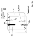
- FIGS. 12 a - 12 y comprise a series of schematic representations of the position of the PMC block for its complete cycle.
- FIG. 13 is a schematic side view of an alternate embodiment of the PMC device showing three faces.
- FIG. 14 is a schematic side view of a further alternate embodiment of the PMC device without a cooling station or blower.
- an Index plastic injection molding machine uses a (preferably rotating) take out turret to extract plastic preforms from a molding unit, and sequentially to move these preforms to a cooling station.
- the cooling station comprises a so-called CoolJetTM device in which a cooling pin is inserted into each preform, cooling air is injected to the interior tip of the preform, and the cooling air flows down the inside surface of the preform to the outside.
- the cooling station may also comprise a so-called SuperCool device in which a cooling pin is inserted into each preform, each preform is pressure-sealed, and cooling air is injected into the interior of the preform.
- the pressure causes the outside walls of the preform to contact the inside walls of the take out cavity, thus effecting cooling on both the inside and outside surfaces of the preform.
- the cooling station may also comprise a combination of CoolJetTM and SuperCool devices and/or equivalent structures. Nevertheless, it should be understood that the teachings and claims of the subject invention are equally applicable to other molding processes used for producing other relatively thick-walled hollow articles. For example, the present invention will find applicability in many molding technologies beyond injected-molded plastic preforms, such as the molding of containers, pails, trays, paint cans, tote boxes, and similar products, or other molded products possibly with non-circular cross-sectional shapes, etc.
- FIG. 1 shows the clamp half of an Index preform molding machine 1 comprising the stationary platen 10 and a rotating turret block assembly 11 .
- the turret block assembly 11 is mounted on journals and is typically carried by two carriers 12 which are releasably connected to the stationary platen 10 by tiebars 13 .
- the ends of the tiebars are releasably connected to clamping piston assemblies 14 mounted to the stationary platen 10 .
- the carriers 12 are guided and slide on linear bearings 15 attached to the machine base 16 .
- the carriers 12 and the molding turret block assembly 11 are moved toward and away from the stationary platen 10 by well-known drive means (not shown).
- Preform mold half 91 (comprising a hot runner and mold cavities) is mounted to the stationary platen 10 and sequentially engages one or more mold cold halves 17 a and 17 b that are mounted to the opposed faces of the molding turret block assembly 11 .
- the molding turret block assembly 11 and the attached mold cold halves 17 can be rotated, for example, by a servo motor 18 via a drive belt 19 and a pulley 20 .
- An injection unit 21 supplies melted resin for injection into the mold.
- a post mold cooling (PMC) device or assembly 30 includes a second pair of carriers 31 a and 31 b that also are guided and slide on linear bearings 15 attached to the machine base 16 .
- a cooling turret block 32 is mounted between the carriers 31 a and 31 b , and is rotatable therebetween.
- the PMC device 30 is movable along the machine base typically through use of a motor drive 90 and a belt 33 such that the assembly can move toward or away from the molding turret block assembly 11 .
- FIG. 2 shows a front view of the PMC device in its unloading orientation.
- the cooling turret block 32 is carried on linear bearings 34 a and 34 b and 35 such that it can move transversely along its axis of rotation or substantially parallel to its axis of rotation between the carriers 31 a and 31 b .
- This motion may be caused by a cylinder 36 that is mounted on the cooling turret block 32 .
- a cylinder rod 37 is attached to a bearing arm 38 that also carries part of the linear bearing assemblies 34 a and 34 b .
- the bearing arm 38 is journaled in the carrier 31 a , and is attached via a gearbox 39 to a servo drive motor 40 that causes the arm 38 and the cooling turret block assembly 32 to rotate.
- the opposed end of the cooling turret block 32 is supported by a rotary services union 41 that is itself supported on a bearing assembly 35 such that the transverse motion of the cooling turret block 32 is guided along the bearing 35 to an outboard position shown in FIG. 4 .
- the amount of this motion is determined by the pitch between the multiple rows of cooling tubes mounted on the PMC mounting plates, to be described below.
- the rotary services union 41 provides a rotary connection for pneumatic, hydraulic, cooling fluid, and electrical services from the machine base to both the cooling turret block 32 and the CoolJetTM/Supercool assembly 42 (to be described below) mounted on top of the carriers 31 a and 31 b . These services are conveyed via flexible conduits 43 from the base 16 to the union 41 so that the supply can be maintained regardless of the position of the PMC on the machine base 16 .
- FIG. 2 also shows the preform cooling tubes 44 mounted on a plate 45 .
- there are 32 tubes mounted on plate 45 these being sufficient for two molding sets produced by an exemplary 16 cavity injection mold.
- a set may comprise any number of tubes greater than or equal to two.
- a plate 45 is mounted on one side, face A, of the cooling turret block 32 .
- a second plate 48 and corresponding tubes 49 (32 in number) are mounted on the opposed face B of the cooling block 32 .
- the tubes are arranged in two alternate sets on each face (e.g., see FIG. 4 ), each set matching the pitch of the injection mold cores.
- the first set aligning with the mold is called row 1 and the second set offset from row 1 by an amount X is called row 2 . If sufficient space allows, additional sets may be provided on each face.
- the total number of tubes on both sides of the cooling turret block 32 can hold four sets of parts molded by the injection unit, thus parts can be treated for four cycles after ejection from the molding turret 11 .
- an extended treatment time can be provided.
- the parts may be treated for two, three, four, or more molding cycles.
- cooling turret block 32 could have more than two faces for mounting sets of tubes.
- FIG. 13 shows an alternate embodiment mounting three such plates, others mounting four or more are also possible. Further, there are situations where the parts being molded are thin enough not to require internal cooling by means of an inserted cooling tube or external cooling by means of a blower. In this situation the machine would be configured as shown in FIG. 14 in which the cooling station atop the carriers 31 a and 31 b and the blower have been removed.
- FIG. 2 also shows the CoolJet/Supercool unit 42 mounted above the cooling turret block 32 .
- the unit is moved vertically by cylinders 50 .
- the unit may comprise only CoolJetTM blowing pins, only SuperCoolTM pins for expansion and cooling of the preforms, or a combination of both types in, for example, alternate sets to provide a variety of treatment options to the preforms 2 presented to the unit.
- the unit includes multiple cooling pins 51 , in a number sufficient to match the corresponding number of cooling tubes 44 on one face of the cooling turret block 32 . In the preferred embodiment, there are 32 cooling pins mounted in a matrix matching the corresponding tubes 44 .
- the cooling pins 51 are mounted on a distributor plate 52 that provides pressurized and/or nonpressurized coolant flow to each cooling pin.
- this plate 52 may simply be a plenum, pressurized by a blower mounted on the unit 42 (not shown). If pressurized cooling fluid (liquid and/or gas) is supplied to the distributor plate 52 , it is conveyed by a flexible conduit 53 that connects the plate 52 to the services union 41 or an alternate point on the PMC device 30 .
- FIG. 1 also shows a blower 60 mounted on the PMC device 30 that can direct a flow of air toward the molded parts while they are still on their cores 70 a on the molding turret 11 , as indicated by arrows F. This allows supplementary cooling of the parts (especially their gate areas) while they are waiting to be transferred to the PMC device 30 .
- the blower 60 is omitted from the views of the PMC device 30 in other figures.
- An alternate embodiment mounts one or more blowers on the cooling turret block 32 or on the carriers 31 a and 31 b such that they are closer to the parts on the cores onto which they are directing their air flow and from such a location that optimizes the flow distribution evenly over the matrix of injection cores on the index block when in the transfer position, as shown in FIG. 1.
- a further alternate embodiment mounts the blowers on the machine base and ducts, mounted on the carriers 31 a and 31 b , align with the blowers when the PMC device is in the transfer position, so to direct the flow distribution evenly over the matrix of injection cores on the index block when in the transfer position, as shown in FIG. 1 .
- the turrets 11 and 32 are configured for rotary movement
- alternative embodiments include molding and/or cooling plates which may be moved linearly or curvelinearly with respect to the mold and the molding/cooling structures, as may be required.
- the Index molding turret block 11 and the mold cold half 17 a are moved to form a closed mold with a hot mold half 91 .
- a clamp force is applied to the mold via, in the preferred embodiment, clamp pistons 14 acting through tiebars 13 .
- the mold is filled by the injection unit 21 , and after a hold and cooling time, the mold is opened by moving the molding turret 11 and the cold half 17 a away from the stationary platen 10 a sufficient distance to clear the rotational arc of the cores 70 a on the molding turret 11 .
- the turret block is rotated through 180 degrees to align the first set of mold cores 70 a carrying the freshly molded parts thereon with the PMC device cooling tubes 44 .
- the second set of mold cores 70 b are now aligned with the cavity half 91 the mold is closed, and the cycle repeated to make a second set of parts on the second set of cores 70 b .
- a typical injection molding cycle time is about 10 seconds.
- the blower 60 directs a cooling flow of air onto the parts on the cores 70 a .
- the PMC device 30 is moved toward the molding turret 11 , and the molded parts on cores 70 a are transferred from the injection molding turret 11 to row 1 of the cooling tubes 44 mounted on face A of the cooling turret block 32 of the PMC device 30 .
- the PMC device 30 is then moved away from the molding turret 11 a sufficient distance to clear the rotational arc of the cooling tubes 44 when loaded with preforms.
- the cooling turret block 32 is then rotated through 90 degrees to align the tubes and their parts vertically with the CoolJetTM/Supercool unit 42 , as shown in FIG. 2 .
- This unit is then moved via cylinders 50 downwards to insert cooling pins 51 into all the preforms in all the tubes 44 , and cooling fluid is ejected from the tubes to cool the interior of the parts.
- the interior of the parts may be pressurized and/or the cooling fluid may be directed to a distal tip of the interior of the part.
- some of the parts 2 in the tubes 49 mounted on the opposed face B of the cooling turret block 32 are ejected beneath the cooling block onto a conveyor (not shown).
- the ejected parts have thus been traveling in the PMC device 30 for four or more molding cycles depending on the number of cooling tube sets installed on the PMC and the number of faces utilized to support cooling tubes. For a 10 second injection molding cycle time the parts will have been treated in the PMC unit for approximately 40 seconds.
- photo eye sensors mounted on the inboard surfaces of the carriers 31 a and 31 b and aligned with reflectors (not shown) mounted on the cooling turret block 32 faces A and B check to ensure the appropriate parts 2 have been completely ejected from the cooling tubes and that any auxiliary ejector bars (not shown) have correctly retracted prior to rotation of the turret block 32 thereby ensuring the risk of equipment collision is avoided.
- An alternate part removal embodiment is by use of a conventional robot device (not shown) mounted on the machine base 16 or the adjacent floor having a take-off plate positioned such that parts can be transferred to it when the cooling turret block 32 is in the transfer position shown in FIG. 1 thereby vacating the cooling tubes slightly earlier in the PMC device cooling cycle.
- the CoolJetTTM/Supercool unit 42 is retracted from its inserted position, shown in FIG. 3 , by the cylinders 50 a sufficient vertical distance to clear the rotational arc of the cooling tubes 44 and their loaded preforms.
- the cooling turret block 32 is then rotated 90 degrees to align the vacated tubes with the next set of freshly molded parts on the mold cores 70 b .
- the parts are transferred and the sequence continues.
- the cooling turret block 32 is moved axially by the cylinder 36 (as the turret rotates) to align the vacated tubes with the next freshly molded parts on the cores 70 a . That is, the cooling turret block 32 is moved axially along an axis parallel to that of its rotation to present the next set of cooling tubes to the parts 2 on the turret cores 70 a or 70 b.
- FIG. 4 shows an arrow X indicating the axial translation of the cooling turret block 32 , to align the vacant tubes during the rotary motion of the cooling block, which is indicated by a rotational arrow R 1 .
- FIG. 5 shows the freshly molded parts 2 loaded into the cooling tubes 44 .
- An arrow Y shows the reverse axial translation of the cooling turret block 32 during the continuing rotation of the cooling block, which is indicated by a rotational arrow R 2 .
- FIG. 6 shows the continuing sequence with the cooling tubes 44 aligned for treatment by the CoolJetTM/Supercool unit 42 .
- all the cooling tubes are loaded with preforms for cooling.
- each of the preforms preferably has two or more treatments from the CoolJetTM/Supercool unit 42 . This ensures that any latent migration of residual heat within the wall sections of even the thickest parts of the preform is treated repeatedly, thereby minimizing the opportunity for recrystallization of the resin to occur.
- a three-sided cooling turret block 32 would result in molded parts being cooled for six molding cycles, and a two-sided cooling turret block would result in molded parts being cooled for four molding cycles.
- varying the number of faces on the cooling block will vary the number of injection molding cycles in which the molded parts can be cooled.
- FIG. 7 shows the ejection of the parts 2 from alternate rows of face A while application of CoolJetTM/Supercool treatment is occurring at face B.
- the sequence continues as shown in FIG. 8 until the parts first loaded into tubes in row 1 face A have been ejected whereupon the sequence recycles.
- four cycles of the injection unit take place. If additional cooling tubes are provided in the PMC device 30 , additional molding cycles of the injection unit may be possible.
- the ejection of the molded parts 2 may be accomplished by mechanical means or pneumatic means, as are well-known in the art.
- FIG. 9 shows a side view of the PMC device 30 just prior to insertion of the CoolJetTM/Supercool cooling pins 51 .
- the PMC device 30 has rotated to accept the just-molded preforms 2 into the vacated cooling tubes 49 .
- FIG. 11 is a sequence chart showing the operations occurring at each stage of the injection molding and cooling cycles.
- FIGS. 12 a - 12 y schematically depict the structure during various phases of the sequence chart. The sequence chart and schematics will be described with respect to injection molding cycles, cooling turret cycles, and those activities that take place in the molding turret 11 and the cooling turret block 32 .
- the control of the various molding and movement operations may be performed with one or more general purpose computers, PCs, processors, application specific integrated circuits, digital signal processors, hard-wired circuits, motors, servomotors, stepper motors, pressure sensors, temperature sensors, etc.
- Injection molding cycle 1 begins when the mold halves close, the clamp is activated, and molten plastic is injected into the mold and held therein for a predetermined period of time.
- the just-molded articles are allowed to cool in the mold for another predetermined period of time, and the mold halves are opened.
- the molding turret 11 is then moved away from the mold cavity half and rotated 180 degrees where the cooling fan 60 blows cooling air on the just-molded parts.
- the molding turret 11 immediately moves back toward the mold cavity half, and injection molding cycle 2 begins, in the meantime the previously molded parts remain on the cores until just before the mold is due to open again.
- the PMC device 30 is moved toward the molding turret 11 and the parts are transferred to the cooling turret block 32 immediately prior to the mold being opened again.
- the previously-molded parts 2 a 1 are loaded into the cooling tubes 44 of row 1 of face A.
- the cooling turret block 32 is then moved away from the molding turret 11 and rotated 90 degrees toward the CoolJetTM/Supercool unit 42 (see FIG. 12 b ).
- the CoolJetTM/Supercool unit 42 is then moved downward, the cooling pins 51 are inserted into the preforms 2 a 1 (see FIG. 12 c ), and the preforms are pressurized and/or cooled (see FIG. 12 d ).
- cooling pins 51 also cool preforms 2 a 2-prior , which are preforms from a prior molding cycle located in row 2 of face A (to be described in greater detail below).
- the preforms 2 a 1 are then vented/blown to complete the cooling engagement, and the cooling unit 42 is moved upward to disengage the cooling pins 51 from the preforms 2 a 1 .
- appropriate mechanical and/or pneumatic means are activated to eject the previously-cooled preforms 2 b 1-prior (from a prior injection molding cycle) from the bottom of cooling turret block 32 (see FIG. 12 e ). This step occurs approximately midway through injection molding cycle 3 .
- the molded preforms 2 b After the molded preforms 2 b have been ejected from the cooling turret block 32 , it is rotated 90 degrees (see FIG. 12 f ) to present the cooling tubes 49 to the molding turret 11 .
- the PMC device 30 is then moved toward molding turret 11 , and previously molded preforms 2 b 1 are transferred to the cooling tubes 49 of row 1 of face B (see FIG. 12 g ).
- the steps described above with respect to preforms 2 a 1 see FIGS. 12 a - 12 f ) are repeated for preforms 2 b 1 (see FIGS. 12 g - 121 ). During these steps, the preforms 2 a 1 on face A of cooling turret block 32 continue to cool.
- FIG. 12 k it is not the above-described preform 2 a 1 which is ejected, but the preform 2 a 2-prior from a prior injection molding cycle which is ejected from row 2 of face A.
- This unloading step also occurs approximately midway through injection molding cycle 4 .
- the cooling turret block 32 is rotated 90 degrees in FIG. 121 , the cooling turret block 32 is moved axially to present the cooling tubes 44 of row 2 of face A to the molding turret 11 .
- the PMC device 30 After rotating and axially translating the cooling turret block 32 , the PMC device 30 is moved toward the molding turret 11 , and preforms 2 a 2 are transferred to the cooling tubes 44 of row 2 of face A of the cooling turret block (see FIG. 12 m ). Thereafter, the same steps as described above with respect to preforms 2 a 1 ( FIGS. 12 a - 12 f ) are repeated for preforms 2 a 2 (see FIGS. 12 m - 12 r ). Note in FIG. 12 p that the cooling pins 51 cool both the preforms 2 a 2 in row 2 of face A, as well as preforms 2 a 1 in row 1 of face A.
- the preforms 2 a 1 are cooled twice by the cooling unit 42 .
- the preforms 2 b 2-prior are ejected while the preforms 2 b 1 remain in the cooling turret block 32 . This step also occurs approximately midway through injection molding cycle 5 .
- preforms 2 b 2 are transferred to the cooling tubes 49 of row 2 of the cooling turret (see FIG. 12 s ).
- preforms 2 a 1 , 2 a 2 , and 2 b 1 remain in the cooling turret block for additional cooling.
- the same steps as described above with respect to preforms 2 b 1 FIGS. 12 g - 12 l ) are repeated for preforms 2 b 2 (see FIGS. 12 s - 12 x ).
- FIG. 12 g - 12 l the same steps as described above with respect to preforms 2 b 1 ( FIGS. 12 g - 12 l ) are repeated for preforms 2 b 2 (see FIGS. 12 s - 12 x ).
- preforms 2 a 1 are finally ejected from the cooling turret block 32 , during injection molding cycle 6 , more than four cycles after their molding, and after rotating one and three-quarters times (630 degrees) around the cooling turret block 32 .
- This extension of the cooling time allows the preforms 2 a 1 to properly solidify without the crystallization problems discussed earlier.
- the cooling turret block 32 is rotated 90 degrees as well as being moved axially to present the cooling tubes 44 of row 1 of face A to the molding turret 11 .
- the cooling turret block 32 is in the same position as that depicted in FIG. 12 a , and the next set of preforms 2 a 1-next are loaded into the cooling tubes 44 of row 1 of face A, and the above-described steps are repeated.
- the above-described steps thus provide an optimized embodiment in which a minimum amount of injection and PMC tooling components are required in order to produce substantially defect-free high quality preform parts at a fast production cycle. Only one cooling station is used and yet two treatment opportunities are provided to each preform. Note, however, that additional cooling stations could be provided at any one or more of the three other positions to which the faces of the cooling turret block are rotated during the above-described process.
Abstract
Description
-
- Crystallinity: The resin recrystallizes due to the elevated temperature of the core resin not cooling quickly enough. The white appearance of the crystals impairs the clarity of the final product and provides an area of potentially weakness in a resultant blown product.
- Surface blemishes: The ejected performs, initially having solidified surfaces are reheated by the core material which causes the surface to soften and be easily marred. Sometimes this surface reheating can be severe enough to cause touching parts to weld together.
- Geometric inaccuracies: Handling partly-cooled performs or attempting to further cool them in devices that do not maintain their geometric shape while their surfaces are reheated can cause the preform's round diameter to become oval shaped or the smooth surface to become wrinkled or non-linear.
-
- A PMC cooling turret block with translational motion preferably along an axis parallel to its axis of rotation.
- A PMC unit that provides two or more separate and possibly different treatment events for each part.
- A PMC unit that carries a blower unit for projecting a stream of cooling air onto the parts positioned on their cores prior to transfer.
Claims (41)
Priority Applications (18)
| Application Number | Priority Date | Filing Date | Title |
|---|---|---|---|
| US10/351,596 US6986653B2 (en) | 2002-05-17 | 2003-01-27 | Post mold cooling apparatus and method having transverse movement |
| MXPA04011211A MXPA04011211A (en) | 2002-05-17 | 2003-04-17 | Post mold cooling apparatus and method having rotational and transverse movement. |
| AT03714587T ATE403534T1 (en) | 2002-05-17 | 2003-04-17 | AFTER-COOLING DEVICE AND METHOD WITH TRANSVERSAL AND ROTATING MOTION |
| BR0310059-6A BR0310059A (en) | 2002-05-17 | 2003-04-17 | Post-mold cooling apparatus and method having rotational and transverse motion |
| CA002482786A CA2482786C (en) | 2002-05-17 | 2003-04-17 | Post mold cooling apparatus and method having rotational and transverse movement |
| RU2004137002/12A RU2294832C2 (en) | 2002-05-17 | 2003-04-17 | Method for cooling after molding with use of rotation and cross motion and apparatus for performing the same |
| EP03714587A EP1515829B1 (en) | 2002-05-17 | 2003-04-17 | Post mold cooling apparatus and method having rotational and transverse movement |
| CNB038112507A CN100404235C (en) | 2002-05-17 | 2003-04-17 | Post mold cooling apparatus and method having rotational and transverse movement |
| PCT/CA2003/000569 WO2003097327A1 (en) | 2002-05-17 | 2003-04-17 | Post mold cooling apparatus and method having rotational and transverse movement |
| JP2004504703A JP4549846B2 (en) | 2002-05-17 | 2003-04-17 | Post-molding cooling apparatus and method with rotational and lateral motion |
| DE60322701T DE60322701D1 (en) | 2002-05-17 | 2003-04-17 | AFTER COOLING DEVICE AND METHOD WITH TRANVERSAL AND ROTATING MOTION |
| AU2003218841A AU2003218841B2 (en) | 2002-05-17 | 2003-04-17 | Post mold cooling apparatus and method having rotational and transverse movement |
| KR1020047018518A KR100642715B1 (en) | 2002-05-17 | 2003-04-17 | Post mold cooling apparatus and method having rotational and transverse movement |
| TW092112348A TW590874B (en) | 2002-05-17 | 2003-05-06 | Post mold cooling apparatus and method having transverse movement |
| IL16465504A IL164655A0 (en) | 2002-05-17 | 2004-10-18 | Post mold cooling apparatus and method having rotational and transverse movement |
| US11/056,272 US7056465B2 (en) | 2002-05-17 | 2005-02-14 | Post mold cooling apparatus and method having transverse movement |
| US11/056,299 US7052270B2 (en) | 2002-05-17 | 2005-02-14 | Post mold cooling apparatus |
| HK06100071.6A HK1080034A1 (en) | 2002-05-17 | 2006-01-04 | Post mold cooling apparatus and method having rotational and transverse movement |
Applications Claiming Priority (2)
| Application Number | Priority Date | Filing Date | Title |
|---|---|---|---|
| US10/147,360 US6817855B2 (en) | 2002-05-17 | 2002-05-17 | Apparatus for post mold cooling of plastic pieces |
| US10/351,596 US6986653B2 (en) | 2002-05-17 | 2003-01-27 | Post mold cooling apparatus and method having transverse movement |
Related Parent Applications (1)
| Application Number | Title | Priority Date | Filing Date |
|---|---|---|---|
| US10/147,360 Continuation-In-Part US6817855B2 (en) | 2002-05-17 | 2002-05-17 | Apparatus for post mold cooling of plastic pieces |
Related Child Applications (2)
| Application Number | Title | Priority Date | Filing Date |
|---|---|---|---|
| US11/056,272 Division US7056465B2 (en) | 2002-05-17 | 2005-02-14 | Post mold cooling apparatus and method having transverse movement |
| US11/056,299 Division US7052270B2 (en) | 2002-05-17 | 2005-02-14 | Post mold cooling apparatus |
Publications (2)
| Publication Number | Publication Date |
|---|---|
| US20030214079A1 US20030214079A1 (en) | 2003-11-20 |
| US6986653B2 true US6986653B2 (en) | 2006-01-17 |
Family
ID=29419000
Family Applications (4)
| Application Number | Title | Priority Date | Filing Date |
|---|---|---|---|
| US10/147,360 Expired - Fee Related US6817855B2 (en) | 2002-05-17 | 2002-05-17 | Apparatus for post mold cooling of plastic pieces |
| US10/351,596 Expired - Fee Related US6986653B2 (en) | 2002-05-17 | 2003-01-27 | Post mold cooling apparatus and method having transverse movement |
| US10/958,124 Expired - Fee Related US7384587B2 (en) | 2002-05-17 | 2004-10-05 | Method for post mold cooling of plastic pieces |
| US10/958,108 Expired - Fee Related US6951452B2 (en) | 2002-05-17 | 2004-10-05 | Cooling station for post mold cooling of plastic pieces |
Family Applications Before (1)
| Application Number | Title | Priority Date | Filing Date |
|---|---|---|---|
| US10/147,360 Expired - Fee Related US6817855B2 (en) | 2002-05-17 | 2002-05-17 | Apparatus for post mold cooling of plastic pieces |
Family Applications After (2)
| Application Number | Title | Priority Date | Filing Date |
|---|---|---|---|
| US10/958,124 Expired - Fee Related US7384587B2 (en) | 2002-05-17 | 2004-10-05 | Method for post mold cooling of plastic pieces |
| US10/958,108 Expired - Fee Related US6951452B2 (en) | 2002-05-17 | 2004-10-05 | Cooling station for post mold cooling of plastic pieces |
Country Status (16)
| Country | Link |
|---|---|
| US (4) | US6817855B2 (en) |
| EP (2) | EP2520407A2 (en) |
| JP (1) | JP4516422B2 (en) |
| KR (2) | KR100642714B1 (en) |
| CN (1) | CN100406231C (en) |
| AT (1) | ATE403534T1 (en) |
| AU (1) | AU2003212166B2 (en) |
| BR (1) | BR0309967A (en) |
| CA (1) | CA2482781C (en) |
| DE (1) | DE60322701D1 (en) |
| HK (1) | HK1080034A1 (en) |
| IL (1) | IL164653A (en) |
| MX (1) | MXPA04011217A (en) |
| RU (1) | RU2293019C2 (en) |
| TW (1) | TWI235107B (en) |
| WO (1) | WO2003097326A1 (en) |
Cited By (9)
| Publication number | Priority date | Publication date | Assignee | Title |
|---|---|---|---|---|
| US20060099297A1 (en) * | 2003-06-23 | 2006-05-11 | Shakal Wayne A | Concurrent cooling mold |
| US20070108668A1 (en) * | 2005-08-30 | 2007-05-17 | Hutchinson Gerald A | Methods and systems for controlling mold temperatures |
| US20070284789A1 (en) * | 2004-06-28 | 2007-12-13 | Sidel Participations | Rotating Machine With Rotating Column for Electricity and Fluid Supply |
| US20080093770A1 (en) * | 2004-03-02 | 2008-04-24 | Matteo Zoppas | Device and method for conditioning plastic objects |
| US20080296801A1 (en) * | 2003-10-07 | 2008-12-04 | S.I.P.A. Societa Industrializzazione Progettazione Automazione S.P.A. | Conditioning Device For Plastic Items And Process |
| US20090051065A1 (en) * | 2007-08-20 | 2009-02-26 | Husky Injection Molding Systems Ltd. | Method for Post-Mold Treatment of a Molded Article and an Apparatus for Implementing the Method |
| US20090146341A1 (en) * | 2007-12-05 | 2009-06-11 | United Technologies Corp. | Systems and Methods Involving Pattern Molds |
| US7645135B2 (en) | 1997-10-17 | 2010-01-12 | Advanced Plastics Technologies Luxembourg S.A. | Mold for injecting molding preforms |
| US9381692B2 (en) | 2013-03-01 | 2016-07-05 | Otto Männer Innovation GmbH | Apparatus and method for injection molding and cooling pet preforms |
Families Citing this family (45)
| Publication number | Priority date | Publication date | Assignee | Title |
|---|---|---|---|---|
| US6817855B2 (en) * | 2002-05-17 | 2004-11-16 | Husky Injection Molding Systems Ltd. | Apparatus for post mold cooling of plastic pieces |
| CA2482786C (en) * | 2002-05-17 | 2007-12-18 | Husky Injection Molding Systems Ltd. | Post mold cooling apparatus and method having rotational and transverse movement |
| EP1558434B2 (en) * | 2002-11-05 | 2017-11-22 | Netstal-Maschinen AG | Method and device for the secondary treatment and the cooling of preforms |
| US7264464B2 (en) * | 2003-06-09 | 2007-09-04 | Husky Injection Molding Systems Ltd. | Cooling tube with a low friction coating |
| ITRM20030460A1 (en) * | 2003-10-07 | 2005-04-08 | Sipa Societa Industrializzazione P Rogettazione A | DEVICE AND PROCESS OF INJECTION OF PLASTIC OBJECTS. |
| DE10355018B4 (en) * | 2003-11-25 | 2011-06-22 | MHT Mold & Hotrunner Technology AG, 65239 | Cavity structure |
| EP1561563A1 (en) * | 2004-02-06 | 2005-08-10 | Battenfeld GmbH | Injection moulding machine |
| US7632089B2 (en) * | 2004-05-07 | 2009-12-15 | Graham Packaging Pet Technologies, Inc. | Take out and cooling system and method |
| WO2007058521A1 (en) * | 2005-11-17 | 2007-05-24 | Tool-Tech Holding B.V. | System and method for transferring and cooling molded hollow plastic articles |
| DE102006028725A1 (en) * | 2005-11-30 | 2007-10-18 | Mht Mold & Hotrunner Technology Ag | Process and system for post-treatment of preforms |
| BE1016968A3 (en) * | 2006-01-27 | 2007-11-06 | Boucherie Nv G B | DEVICE FOR MANUFACTURING injection molding. |
| DE102006007639A1 (en) * | 2006-02-18 | 2007-08-23 | Mht Mold & Hotrunner Technology Ag | recording system |
| US7802980B2 (en) * | 2007-04-18 | 2010-09-28 | Husky Injection Molding Systems Ltd. | System, method and apparatus for configuring an end of arm tool in a molding system |
| US20090200698A1 (en) * | 2006-06-12 | 2009-08-13 | Husky Injection Molding Systems Ltd. | Method and apparatus for post-mold cooling a molded article |
| US7421310B2 (en) * | 2006-06-12 | 2008-09-02 | Husky Injection Molding Systems Ltd. | Method and apparatus for controlling cooling rates during post-mold cooling of a molded article |
| DE102006028723A1 (en) | 2006-06-20 | 2008-01-03 | Mht Mold & Hotrunner Technology Ag | positioning |
| US7595018B2 (en) * | 2006-10-16 | 2009-09-29 | Husky Injection Molding Systems Ltd. | Molded article picker |
| US20080166209A1 (en) * | 2007-01-10 | 2008-07-10 | Husky Injection Molding Systems Ltd. | Molded Article Picker |
| US20080265465A1 (en) * | 2007-04-24 | 2008-10-30 | Husky Injection Molding Systems Ltd. | Apparatus for Injection Compression Molding and Method of Molding Articles |
| US7905721B2 (en) * | 2007-06-05 | 2011-03-15 | Husky Injection Molding Systems Ltd. | Air source device and a method for use in a molding system |
| US7473093B1 (en) * | 2007-09-28 | 2009-01-06 | Husky Injection Molding Systems Ltd. | Molded article picker |
| EP2065158B1 (en) | 2007-11-27 | 2018-05-30 | Plastipak BAWT S.à.r.l. | Cooling pin for cooling a hollow moulded plastic piece by means of a cooling fluid flow boosted by venturi effect |
| US20090233541A1 (en) * | 2008-03-12 | 2009-09-17 | Air Vent, Inc. | Molding process for ridge vents and other index molded products |
| KR101045391B1 (en) * | 2008-06-27 | 2011-06-30 | 주식회사 아성프라텍 | Apparatus for cooling ECU case of vehicle |
| JP5305977B2 (en) * | 2009-02-24 | 2013-10-02 | 富士フイルム株式会社 | Cooling method and apparatus for injection molded product |
| DE102009026298A1 (en) * | 2009-07-31 | 2011-02-24 | Krones Ag | Apparatus and method for blow molding plastic containers |
| US8740610B2 (en) * | 2009-11-30 | 2014-06-03 | Huskey Injection Molding Systems Ltd. | Molding apparatus |
| DE102009059039A1 (en) * | 2009-12-11 | 2011-06-16 | Marbach Moulds & Automation Gmbh | Insertion stamp and method for inserting banderole and floor label in an injection mold |
| CN102092124A (en) * | 2011-01-27 | 2011-06-15 | 浙江德玛克机械有限公司 | Cooling device for embryo taking suction tube of injection molding machine |
| KR101420778B1 (en) * | 2012-03-02 | 2014-07-17 | 주식회사 아성프라텍 | Cooling apparatus for preventing demensional tolerance of injection molding products |
| US9248597B2 (en) * | 2012-04-02 | 2016-02-02 | Progressive Components International Corporation | Bubbler base |
| CN106536159B (en) * | 2014-07-17 | 2020-06-19 | 萨克米伊莫拉有限公司 | Device for unloading and storing preforms for producing containers made of plastic |
| DE102014112438A1 (en) * | 2014-08-29 | 2016-03-03 | Mht Mold & Hotrunner Technology Ag | System for the further treatment of preforms produced by injection molding |
| WO2016149383A1 (en) * | 2015-03-17 | 2016-09-22 | Mold-Masters (2007) Limited | Post mold cooling system |
| US10052804B2 (en) * | 2015-03-20 | 2018-08-21 | Athena Automation Ltd. | Cooling plate assembly for an injection molding machine |
| US10898821B2 (en) | 2015-06-02 | 2021-01-26 | Moose Creative Management Pty Limited | Adhesive toy beads |
| US20170087480A1 (en) * | 2015-06-02 | 2017-03-30 | Moose Creative Management Pty Limited | Adhesive toy beads |
| AT523705B1 (en) * | 2017-02-24 | 2021-11-15 | Niigon Machines Ltd | Injection molding machine for casting preforms |
| KR20230107703A (en) | 2019-03-20 | 2023-07-17 | 닛세이 에이. 에스. 비 기카이 가부시키가이샤 | Method for manufacturing resin container, blow molding apparatus, blow molding mold, and temperature adjustment mold |
| CN109968632B (en) * | 2019-05-11 | 2020-11-24 | 苏州晴朗工业科技有限公司 | Precision injection-blow mold for cosmetic packaging bottle production and production method thereof |
| FR3099080B1 (en) * | 2019-07-22 | 2022-11-04 | Arkema France | METHOD FOR MANUFACTURING A PART IN COMPOSITE MATERIAL USING A MOLD WITH THIN WALLS |
| CN110667062B (en) * | 2019-10-18 | 2021-09-07 | 东台市高科技术创业园有限公司 | Two-way cold antiseized even drawing of patterns apparatus for producing of joining of patterns of different bore connecting pipe |
| CN110871546A (en) * | 2020-01-02 | 2020-03-10 | 芜湖蓝博塑胶有限公司 | Air conditioner injection molding discharging device that moulds plastics |
| CN112339220A (en) * | 2020-09-24 | 2021-02-09 | 重庆优创电子科技有限公司 | Cooling protection device for mold temperature controller |
| CN112171997B (en) * | 2020-09-27 | 2022-07-12 | 河南超诚建材科技有限公司 | Forming die is used in production of building insulation board |
Citations (14)
| Publication number | Priority date | Publication date | Assignee | Title |
|---|---|---|---|---|
| US4729732A (en) | 1985-05-14 | 1988-03-08 | Husky Injection Molding Systems Ltd. | Carrying means for holding and cooling a parison |
| USRE33237E (en) | 1987-03-23 | 1990-06-19 | Husky Injection Molding Systems Ltd. | Apparatus for producing hollow plastic articles |
| US4950152A (en) | 1988-12-05 | 1990-08-21 | Electra Form, Inc. | Apparatus for producing preforms and blow molded articles |
| US5447426A (en) | 1993-07-06 | 1995-09-05 | Husky Injection Molding Systems Ltd. | Take-off plate device |
| EP0283644B2 (en) | 1987-03-23 | 1996-10-23 | Husky Injection Molding Systems Ltd. | Apparatus for producing hollow plastic articles |
| US5679306A (en) | 1993-10-22 | 1997-10-21 | A.K. Technical Laboratory, Inc. | Method of molding preform in injection stretch blow molding |
| WO1997039874A1 (en) | 1996-04-18 | 1997-10-30 | Sipa S.P.A. | Improvement in the method and plant for manufacturing thermoplastic-resin parisons |
| US5728409A (en) | 1996-03-06 | 1998-03-17 | Husky Injection Molding Systems Ltd. | Turret article molding machine |
| US5750162A (en) | 1996-03-06 | 1998-05-12 | Husky Injection Molding Systems Ltd. | Turret article molding machine including blow molding station |
| US5817345A (en) | 1996-03-06 | 1998-10-06 | Husky Injection Molding System Ltd. | Turrent article molding machine and method of use |
| US6059557A (en) | 1998-10-07 | 2000-05-09 | Husky Injection Molding Systems Ltd. | Cooling device attached to index machine |
| EP1013398A1 (en) | 1998-12-21 | 2000-06-28 | Husky Injection Molding Systems Ltd. | Cooling device attached to index machine |
| US6143225A (en) | 1999-03-03 | 2000-11-07 | Husky Injection Molding Systems Ltd. | Turret cooling block for an index machine |
| US6171541B1 (en) | 1998-03-31 | 2001-01-09 | Husky Injection Molding Systems Ltd. | Preform post-mold cooling method and apparatus |
Family Cites Families (19)
| Publication number | Priority date | Publication date | Assignee | Title |
|---|---|---|---|---|
| US33237A (en) * | 1861-09-10 | Window-sash fastener | ||
| US4449913A (en) | 1981-02-23 | 1984-05-22 | The Continental Group, Inc. | Rotary injection turret for the making of preforms |
| FR2561166B1 (en) * | 1984-03-16 | 1986-10-10 | Pont A Mousson | PROCESS FOR THE MANUFACTURE OF PLASTIC BOTTLES FROM HOLLOW BLANKS OBTAINED BY MOLDING AND DEVICES FOR CARRYING OUT SAID METHOD |
| SU1399149A1 (en) * | 1986-09-03 | 1988-05-30 | Одесское Производственное Объединение "Прессмаш" Им.60-Летия Октября | Device for removing and transfering articles in moulding machine |
| US4836767A (en) | 1987-11-25 | 1989-06-06 | Husky Injection Molding System, Ltd. | Swing plate molding machine |
| US5154309A (en) * | 1991-01-07 | 1992-10-13 | Rock-Tenn Company | Insulating blanket for shipping container having scored mineral wool |
| US5114327A (en) * | 1991-01-25 | 1992-05-19 | Williamson James T | Rapid cooling apparatus for an injection molding machine |
| CN1063443A (en) * | 1991-01-25 | 1992-08-12 | 乔布斯特·乌尔里克·盖勒特 | The Coinjection molding apparatus that in the front portion of nozzle, has whole cooling |
| NL9201738A (en) * | 1992-10-08 | 1994-05-02 | Inter Tooling Services Bv | Injection molding device. |
| RU2091229C1 (en) * | 1994-09-16 | 1997-09-27 | Виндмеллер унд Хелшир | Method of variable peripheral cooling of film hose made of extruded thermoplastic artificial material |
| DE19518118C2 (en) | 1995-05-17 | 1998-06-18 | Sun Chemical Corp | Photosensitive composition |
| US6142225A (en) * | 1996-05-01 | 2000-11-07 | Baker Hughes Incorporated | Selective mono bore diverter system |
| IL138727A (en) * | 1998-03-31 | 2005-05-17 | Husky Injection Molding | Preform post-mold cooling method and apparatus |
| US6299431B1 (en) * | 1998-07-28 | 2001-10-09 | Husky Injection Molding Systems Ltd. | Cooling apparatus for injection molding machines |
| US6221305B1 (en) * | 1998-11-23 | 2001-04-24 | Milacron Inc. | Compression molded neck body with smooth inner wall |
| US6168416B1 (en) * | 1998-12-22 | 2001-01-02 | Husky Injection Molding Systems Ltd. | Cooling device for molded articles |
| JP4266434B2 (en) * | 1999-04-12 | 2009-05-20 | 日精エー・エス・ビー機械株式会社 | Preform cooling device |
| US6422855B1 (en) * | 2000-12-22 | 2002-07-23 | Husky Injection Molding Systems, Ltd. | Device for temperature adjustment of an object |
| US6817855B2 (en) * | 2002-05-17 | 2004-11-16 | Husky Injection Molding Systems Ltd. | Apparatus for post mold cooling of plastic pieces |
-
2002
- 2002-05-17 US US10/147,360 patent/US6817855B2/en not_active Expired - Fee Related
-
2003
- 2003-01-27 US US10/351,596 patent/US6986653B2/en not_active Expired - Fee Related
- 2003-03-24 EP EP12176525A patent/EP2520407A2/en not_active Withdrawn
- 2003-03-24 EP EP03707978.7A patent/EP1515828B1/en not_active Expired - Lifetime
- 2003-03-24 CA CA002482781A patent/CA2482781C/en not_active Expired - Fee Related
- 2003-03-24 JP JP2004504702A patent/JP4516422B2/en not_active Expired - Fee Related
- 2003-03-24 AU AU2003212166A patent/AU2003212166B2/en not_active Ceased
- 2003-03-24 CN CNB038112019A patent/CN100406231C/en not_active Expired - Fee Related
- 2003-03-24 BR BR0309967-9A patent/BR0309967A/en not_active IP Right Cessation
- 2003-03-24 MX MXPA04011217A patent/MXPA04011217A/en active IP Right Grant
- 2003-03-24 WO PCT/CA2003/000414 patent/WO2003097326A1/en active Application Filing
- 2003-03-24 KR KR1020047018499A patent/KR100642714B1/en not_active IP Right Cessation
- 2003-03-24 RU RU2004137003/12A patent/RU2293019C2/en not_active IP Right Cessation
- 2003-04-17 KR KR1020047018518A patent/KR100642715B1/en not_active IP Right Cessation
- 2003-04-17 AT AT03714587T patent/ATE403534T1/en active
- 2003-04-17 TW TW092108921A patent/TWI235107B/en not_active IP Right Cessation
- 2003-04-17 DE DE60322701T patent/DE60322701D1/en not_active Expired - Lifetime
-
2004
- 2004-10-05 US US10/958,124 patent/US7384587B2/en not_active Expired - Fee Related
- 2004-10-05 US US10/958,108 patent/US6951452B2/en not_active Expired - Fee Related
- 2004-10-18 IL IL164653A patent/IL164653A/en not_active IP Right Cessation
-
2006
- 2006-01-04 HK HK06100071.6A patent/HK1080034A1/en unknown
Patent Citations (17)
| Publication number | Priority date | Publication date | Assignee | Title |
|---|---|---|---|---|
| US4729732A (en) | 1985-05-14 | 1988-03-08 | Husky Injection Molding Systems Ltd. | Carrying means for holding and cooling a parison |
| USRE33237E (en) | 1987-03-23 | 1990-06-19 | Husky Injection Molding Systems Ltd. | Apparatus for producing hollow plastic articles |
| EP0283644B2 (en) | 1987-03-23 | 1996-10-23 | Husky Injection Molding Systems Ltd. | Apparatus for producing hollow plastic articles |
| US4950152A (en) | 1988-12-05 | 1990-08-21 | Electra Form, Inc. | Apparatus for producing preforms and blow molded articles |
| US5447426A (en) | 1993-07-06 | 1995-09-05 | Husky Injection Molding Systems Ltd. | Take-off plate device |
| US5679306A (en) | 1993-10-22 | 1997-10-21 | A.K. Technical Laboratory, Inc. | Method of molding preform in injection stretch blow molding |
| US5750162A (en) | 1996-03-06 | 1998-05-12 | Husky Injection Molding Systems Ltd. | Turret article molding machine including blow molding station |
| US5728409A (en) | 1996-03-06 | 1998-03-17 | Husky Injection Molding Systems Ltd. | Turret article molding machine |
| US5817345A (en) | 1996-03-06 | 1998-10-06 | Husky Injection Molding System Ltd. | Turrent article molding machine and method of use |
| US5830404A (en) | 1996-03-06 | 1998-11-03 | Husky Injection Molding Systems Ltd. | Turret article molding machine process |
| WO1997039874A1 (en) | 1996-04-18 | 1997-10-30 | Sipa S.P.A. | Improvement in the method and plant for manufacturing thermoplastic-resin parisons |
| US6171541B1 (en) | 1998-03-31 | 2001-01-09 | Husky Injection Molding Systems Ltd. | Preform post-mold cooling method and apparatus |
| US6059557A (en) | 1998-10-07 | 2000-05-09 | Husky Injection Molding Systems Ltd. | Cooling device attached to index machine |
| US6123538A (en) | 1998-10-07 | 2000-09-26 | Husky Injection Molding Systems Ltd. | Cooling device attached to an index machine |
| EP1013398A1 (en) | 1998-12-21 | 2000-06-28 | Husky Injection Molding Systems Ltd. | Cooling device attached to index machine |
| US6113834A (en) | 1998-12-21 | 2000-09-05 | Husky Injection Molding Systems Ltd. | Cooling device attached to index machine |
| US6143225A (en) | 1999-03-03 | 2000-11-07 | Husky Injection Molding Systems Ltd. | Turret cooling block for an index machine |
Cited By (17)
| Publication number | Priority date | Publication date | Assignee | Title |
|---|---|---|---|---|
| US7645135B2 (en) | 1997-10-17 | 2010-01-12 | Advanced Plastics Technologies Luxembourg S.A. | Mold for injecting molding preforms |
| US7331779B2 (en) * | 2003-06-23 | 2008-02-19 | Advanced Tool, Inc. | Concurrent cooling mold |
| US20060099297A1 (en) * | 2003-06-23 | 2006-05-11 | Shakal Wayne A | Concurrent cooling mold |
| US8246338B2 (en) * | 2003-10-07 | 2012-08-21 | S.I.P.A. Societa Industrializzazione Progettazione E Automazione S.P.A. | Conditioning device for plastic items and process |
| US20080296801A1 (en) * | 2003-10-07 | 2008-12-04 | S.I.P.A. Societa Industrializzazione Progettazione Automazione S.P.A. | Conditioning Device For Plastic Items And Process |
| US20080093770A1 (en) * | 2004-03-02 | 2008-04-24 | Matteo Zoppas | Device and method for conditioning plastic objects |
| US7700029B2 (en) * | 2004-03-02 | 2010-04-20 | S.I.P.A. Societa Industrializzazione Progettazione E Automazione S.P.A. | Device and method for conditioning plastic objects |
| US20070284789A1 (en) * | 2004-06-28 | 2007-12-13 | Sidel Participations | Rotating Machine With Rotating Column for Electricity and Fluid Supply |
| US7699599B2 (en) * | 2004-06-28 | 2010-04-20 | Sidel Participations | Rotating machine with rotating column for electricity and fluid supply |
| US7717697B2 (en) | 2005-08-30 | 2010-05-18 | Sharon Hutchinson | Methods and systems for controlling mold temperatures |
| US20070108668A1 (en) * | 2005-08-30 | 2007-05-17 | Hutchinson Gerald A | Methods and systems for controlling mold temperatures |
| WO2009023950A1 (en) * | 2007-08-20 | 2009-02-26 | Husky Injection Molding Systems Ltd. | A method for post-mold treatment of a molded article and an apparatus for implementing the method |
| US20090051065A1 (en) * | 2007-08-20 | 2009-02-26 | Husky Injection Molding Systems Ltd. | Method for Post-Mold Treatment of a Molded Article and an Apparatus for Implementing the Method |
| US7780884B2 (en) | 2007-08-20 | 2010-08-24 | Husky Injection Molding Systems Ltd. | Method for post-mold treatment of a molded article and an apparatus for implementing the method |
| US20090146341A1 (en) * | 2007-12-05 | 2009-06-11 | United Technologies Corp. | Systems and Methods Involving Pattern Molds |
| US8083511B2 (en) * | 2007-12-05 | 2011-12-27 | United Technologies Corp. | Systems and methods involving pattern molds |
| US9381692B2 (en) | 2013-03-01 | 2016-07-05 | Otto Männer Innovation GmbH | Apparatus and method for injection molding and cooling pet preforms |
Also Published As
Similar Documents
| Publication | Publication Date | Title |
|---|---|---|
| US6986653B2 (en) | Post mold cooling apparatus and method having transverse movement | |
| US7052270B2 (en) | Post mold cooling apparatus | |
| US7264463B2 (en) | Platen mounted post mold cooling apparatus and method | |
| EP0283644B2 (en) | Apparatus for producing hollow plastic articles | |
| USRE33237E (en) | Apparatus for producing hollow plastic articles | |
| EP1115543B1 (en) | Compact post-mold cooling device | |
| US6143225A (en) | Turret cooling block for an index machine | |
| US6332770B1 (en) | Apparatus for localized preform cooling outside the mold | |
| US20140319732A1 (en) | Apparatus and method for injection molding and cooling pet preforms | |
| US7946836B2 (en) | Injection molding and temperature conditioning apparatus | |
| GB2293344A (en) | Cooling injection and blow moulded parisons | |
| JP2902119B2 (en) | Preform injection molding method and apparatus |
Legal Events
| Date | Code | Title | Description |
|---|---|---|---|
| AS | Assignment |
Owner name: HUSKY INJECTION MOLDING SYSTEMS, LTD., CANADA Free format text: ASSIGNMENT OF ASSIGNORS INTEREST;ASSIGNORS:UNTERLANDER, RICHARD M.;NETER, WITOLD;ROMANSKI, ZBIGNIEW;AND OTHERS;REEL/FRAME:014037/0322;SIGNING DATES FROM 20030403 TO 20030411 |
|
| AS | Assignment |
Owner name: HUSKY INJECTION MOLDING SYSTEMS INC., NEW YORK Free format text: ASSIGNMENT OF ASSIGNORS INTEREST;ASSIGNOR:HUSKY INJECTION MOLDING SYSTEMS LTD.;REEL/FRAME:013823/0742 Effective date: 20030722 |
|
| AS | Assignment |
Owner name: ROYAL BANK OF CANADA, CANADA Free format text: SECURITY AGREEMENT;ASSIGNOR:HUSKY INJECTION MOLDING SYSTEMS LTD.;REEL/FRAME:020431/0495 Effective date: 20071213 Owner name: ROYAL BANK OF CANADA,CANADA Free format text: SECURITY AGREEMENT;ASSIGNOR:HUSKY INJECTION MOLDING SYSTEMS LTD.;REEL/FRAME:020431/0495 Effective date: 20071213 |
|
| FPAY | Fee payment |
Year of fee payment: 4 |
|
| AS | Assignment |
Owner name: HUSKY INJECTION MOLDING SYSTEMS LTD., CANADA Free format text: RELEASE OF SECURITY AGREEMENT;ASSIGNOR:ROYAL BANK OF CANADA;REEL/FRAME:026647/0595 Effective date: 20110630 |
|
| FPAY | Fee payment |
Year of fee payment: 8 |
|
| FEPP | Fee payment procedure |
Free format text: MAINTENANCE FEE REMINDER MAILED (ORIGINAL EVENT CODE: REM.) |
|
| LAPS | Lapse for failure to pay maintenance fees |
Free format text: PATENT EXPIRED FOR FAILURE TO PAY MAINTENANCE FEES (ORIGINAL EVENT CODE: EXP.) |
|
| STCH | Information on status: patent discontinuation |
Free format text: PATENT EXPIRED DUE TO NONPAYMENT OF MAINTENANCE FEES UNDER 37 CFR 1.362 |
|
| FP | Lapsed due to failure to pay maintenance fee |
Effective date: 20180117 |