US6987820B1 - Apparatus for navigation satellite signal quality monitoring - Google Patents
Apparatus for navigation satellite signal quality monitoring Download PDFInfo
- Publication number
- US6987820B1 US6987820B1 US09/691,690 US69169000A US6987820B1 US 6987820 B1 US6987820 B1 US 6987820B1 US 69169000 A US69169000 A US 69169000A US 6987820 B1 US6987820 B1 US 6987820B1
- Authority
- US
- United States
- Prior art keywords
- correlation
- signal distortion
- signal
- deviations
- differences
- Prior art date
- Legal status (The legal status is an assumption and is not a legal conclusion. Google has not performed a legal analysis and makes no representation as to the accuracy of the status listed.)
- Expired - Lifetime, expires
Links
Images


Classifications
-
- G—PHYSICS
- G01—MEASURING; TESTING
- G01S—RADIO DIRECTION-FINDING; RADIO NAVIGATION; DETERMINING DISTANCE OR VELOCITY BY USE OF RADIO WAVES; LOCATING OR PRESENCE-DETECTING BY USE OF THE REFLECTION OR RERADIATION OF RADIO WAVES; ANALOGOUS ARRANGEMENTS USING OTHER WAVES
- G01S19/00—Satellite radio beacon positioning systems; Determining position, velocity or attitude using signals transmitted by such systems
- G01S19/01—Satellite radio beacon positioning systems transmitting time-stamped messages, e.g. GPS [Global Positioning System], GLONASS [Global Orbiting Navigation Satellite System] or GALILEO
- G01S19/13—Receivers
- G01S19/22—Multipath-related issues
-
- G—PHYSICS
- G01—MEASURING; TESTING
- G01S—RADIO DIRECTION-FINDING; RADIO NAVIGATION; DETERMINING DISTANCE OR VELOCITY BY USE OF RADIO WAVES; LOCATING OR PRESENCE-DETECTING BY USE OF THE REFLECTION OR RERADIATION OF RADIO WAVES; ANALOGOUS ARRANGEMENTS USING OTHER WAVES
- G01S19/00—Satellite radio beacon positioning systems; Determining position, velocity or attitude using signals transmitted by such systems
- G01S19/01—Satellite radio beacon positioning systems transmitting time-stamped messages, e.g. GPS [Global Positioning System], GLONASS [Global Orbiting Navigation Satellite System] or GALILEO
- G01S19/13—Receivers
- G01S19/24—Acquisition or tracking or demodulation of signals transmitted by the system
- G01S19/30—Acquisition or tracking or demodulation of signals transmitted by the system code related
Definitions
- the present invention relates generally to satellite based positioning systems such as the Global Positioning System (GPS) and more particularly to the monitoring of the quality of the signals transmitted by satellites in a satellite based positioning system.
- GPS Global Positioning System
- a satellite based positioning system is used to determine a position of a receiver and typically includes satellite control facilities, a plurality of satellites, the receiver, and one or more local or regional ground stations. Each of the satellites transmits a signal that contains a code and certain prescribed information useful to the receiver in determining its position.
- the receiver synchronizes itself to the codes of at least four satellites and uses the information in the signals from these satellites in order to perform a triangulation like procedure so as to determine its coordinates and time offset with respect to a reference, such as the center of the Earth and the GPS standard time.
- the receiver is not constrained to a specific location and, therefore, represents a variable position. Indeed, the purpose of the satellite based positioning system is to make it possible for the receiver to determine its position regardless of the location of the receiver.
- the local or regional ground station is in a fixed location and is used to monitor the signals transmitted by the satellites. The signals transmitted by the satellites can be adversely affected, for example, by atmospheric conditions which can lead to improper position determinations by the receiver. The ground station, therefore, notifies the receiver of any necessary signal corrections to allow the receiver to make more accurate position calculations. This arrangement is referred to as differential positioning.
- the ground station of the present invention also monitors the signals transmitted by the satellites in order to detect faults within the satellites. For GPS, these faults are specified by the FAA who imposes stringent requirements to protect users against positioning system signal faults. A set of test waveforms has been chosen by the FAA to represent at least some of the more egregious faults. These waveforms are used for certification testing of the ground station equipment.
- the prior art determines faults by comparing conventional code tracking discriminators at different correlator spacings.
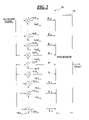
- a correlation curve is established by correlating the code received from a satellite with a suite of code references which are time shifted replicas of the code transmitted by that satellite. For example, seven correlation measurements may be calculated as shown in FIG. 1 .
- the in-phase measurement IP represents the amount of correlation between the received code and a reference code that has a zero time shift with respect to the received code (this measurement is referred to as punctual).
- the in-phase measurement IE 1 represents the amount of correlation between the received code and a reference code that has a first predetermined time shift so that it is early with respect to the received code.
- the in-phase measurement IL 1 represents the amount of correlation between the received code and a reference code that has a second predetermined time shift so that it is late with respect to the received code.
- the in-phase measurement IE 2 is derived using a third predetermined time shift
- the in-phase measurement IL 2 is derived using a fourth predetermined time shift
- the in-phase measurement IE 3 is derived using a fifth predetermined time shift
- the in-phase measurement IL 3 is derived using a sixth predetermined time shift.
- the magnitude of the first predetermined time shift may be equal to the magnitude of the second predetermined time shift
- the magnitude of the third predetermined time shift may be equal to the magnitude of the fourth predetermined time shift
- the magnitude of the fifth predetermined time shift may be equal to the magnitude of the sixth predetermined time shift. It is assumed that all measurements are normalized such that the measured correlation is a function of the time shifts only and not the absolute power of the received satellite signal.
- d 1,2
- d 1,3
- d 2,3
- the quantities d 1,2 , d 1,3 , and d 2,3 are compared to corresponding thresholds D 1,2 , D 1,3 , and D 2,3 such that, if the first discriminator d 1,2 exceeds D 1,2 , if the second discriminator d 1,3 exceeds D 1,3 , or if the third discriminator d 2,3 exceeds D 2,3 , a fault is assumed to exist.
- At least one of the problems with this method is that it is requires six correlators in order to determine the three quantities d 1,2 , d 1,3 , and d 2,3 which is too much hardware for the amount of useful data being provided.
- the present invention is directed to an arrangement which overcomes one or more problems of the prior art.
- an apparatus for the detection of positioning system satellite signal faults comprises a correlator and a fault detector.
- the correlator determines a plurality of correlation measurements at points along a correlation curve, and each correlation measurement is based upon a correlation between a received satellite signal and a reference.
- the fault detector determines differences between the correlation measurements along the correlation curve and detects a fault from the differences.
- a method of detecting faults affecting a signal transmitted by a positioning system satellite comprises: correlating the transmitted signal with a first reference in order to determine a first correlation measurement at a first point along a correlation curve; correlating the transmitted signal with a second reference in order to determine a second correlation measurement at a second point along the correlation curve; correlating the transmitted signal with a third reference in order to determine a third correlation measurement at a third point along the correlation curve; determining a first difference from the first and second correlation measurements; determining a second difference from the second and third correlation measurements; directly comparing the first difference to a first threshold; directly comparing the second difference to a second threshold; and, detecting a fault in the satellite based upon the comparisons of the first and second differences to the first and second thresholds.
- a method of detecting faults affecting a signal transmitted by a positioning system satellite comprises: correlating the transmitted signal with references in order to determine a plurality of correlation measurements at corresponding points along a correlation curve; determining a single value from n pairs of the correlation measurements, wherein n>2; comparing the single value to a threshold; and, detecting a fault in the satellite based upon the comparison.
- FIG. 1 is a waveform showing a correlation diagram useful in explaining prior art fault detection as implemented in a ground station in a global positioning system
- FIG. 2 is a schematic diagram of a portion of a ground station receiver pertinent to the present invention.
- FIG. 3 is a waveform showing a correlation diagram useful in explaining fault detection as implemented by a ground station in a global positioning system in accordance with the present invention.
- FIG. 2 A portion of a ground station 10 pertinent to the present invention is shown in FIG. 2 .
- the ground station has correlators 12 -E m , . . . , 12 -E 3 , 12 -E 2 , 12 -E 1 , 12 -P, 12 -L 1 , 12 -L 2 , 12 -L 3 , . . . , 12 -L n , where n+m is greater than two, and where n is the number of late correlation measurements and m is the number of early correlation measurements to be used in determining a fault.
- the correlator 12 -P correlates the usual code in the received signal with a reference 14 -P to produce a punctual correlation output IP
- the correlator 12 -L 1 correlates the code in the received signal with a reference 14 -L 1 to produce a late correlation output IL 1
- the correlator 12 -L 2 correlates the code in the received signal with a reference 14 -L 2 to produce a late correlation output IL 2
- the correlator 12 -L 3 correlates the code in the received signal with a reference 14 -L 3 to produce a late correlation output IL 3
- the correlator 12 -L n correlates the code in the received signal with a reference 14 -L n to produce a late correlation output IL n .
- a correlator 12 -E 1 correlates the code in the received signal with a reference 14 -E 1 to produce an early correlation output IE 1
- a correlator 12 -E 2 correlates the code in the received signal with a reference 14 -E 2 to produce an early correlation output IE 2
- a correlator 12 -E 3 correlates the code in the received signal with a reference 14 -E 3 to produce an early correlation output IE 3
- a correlator 12 -E m correlates the code in the received signal with a reference 14 -E m to produce an early correlation output IE m .
- the ground station 10 has a processor 16 which uses the punctual and late correlation outputs IP, IL 1 , IL 2 , IL 3 , . . . , IL n as disclosed hereinafter in order to determined whether a fault exists.
- the processor 16 can use the early correlation outputs IE 1 , IE 2 , IE 3 , . . . , IE m as disclosed hereinafter in order to determine whether a fault exists.
- the processor 16 shifts the reference 14 -P, which may be a replica of the code contained in the received signal, until an optimum correlation is obtained.
- the processor 16 controls the reference 14 -L 1 so that the reference 14 -L 1 is a replica of the reference 14 -P and so that the reference 14 -L 1 is time shifted with respect to the reference 14 -P by a first predetermined amount of time. Accordingly, the correlator 12 -L 1 produces the late correlation output IL 1 .
- the processor 16 also controls the reference 14 -L 2 so that the reference 14 -L 2 is a replica of the reference 14 -P and so that the reference 14 -L 2 is time shifted with respect to the reference 14 -P by a second predetermined amount of time, where the second predetermined amount of time is greater than the first predetermined amount of time. Accordingly, the correlator 12 -L 2 produces the late correlation output IL 2 .
- the processor 16 controls the reference 14 -L 3 so that the reference 14 -L 3 is a replica of the reference 14 -P and so that the reference 14 -L 3 is time shifted with respect to the reference 14 -P by a third predetermined amount of time, where the third predetermined amount of time is greater than the first and second predetermined amounts of time.
- the correlator 12 -L 3 produces the late correlation output IL 3 .
- the remaining late correlation outputs up to IL n are generated in a like manner.
- the first, second, third, etc. predetermined amounts of time are all chosen so that the late correlation outputs IL 1 through IL n are all on the downward or late slope of the correlation curve as shown in FIG. 3 .
- the correlators 12 -E 1 , 12 -E 2 , 12 -E 3 , . . . , 12 -E m may be positioned so as to generate the early correlation outputs IE 1 , IE 2 , IE 3 , . . . , IE m .
- quadrature phase correlation outputs QE m , . . . QE 1 , QP, QL 1 , . . . , QL n may be generated by correlating the code in the received signal to a time shifted quadrature form of the reference 14 -P.
- each measurement used to generate a fault indication may be formed as an RMS (Root Mean Square) value of the corresponding in phase and quadrature phase measurements.
- the set IE m , . . . , IE 3 , IE 2 , IE 1 , IP, IL 1 , IL 2 , IL 3 , . . . , IL n may be denoted as I m , . . . , I ⁇ 3 , I ⁇ 2 , I ⁇ 1 , I 0 , I 1 , I 2 , I 3 , . . . , I n and the following corresponding set of RMS values
- the processor 16 processes the early correlation outputs IE m through IE 1 , the punctual correlation output IP, and/or the late correlation outputs IL 1 through IL n so as to derive one or more measured differences d i,j .
- the measured differences d i,j may be affected by thermal and multipath noise which could lead to false detection of faults, depending upon the sensitivity of the fault detection apparatus, i.e., the magnitudes of the thresholds D i,j . Accordingly, in these cases, a fault could be detected when no fault is in fact present, or a fault which is present might not be detected at all.
- the thermal noise content in d i,j can be determined as a function of the delay h i,j between the reference codes 14 -E m , . . . , 14 -E 3 , 14 -E 2 , 14 -E 1 , 14 -P, 14 -L 1 , 14 -L 2 , 14 -L 3 , . . . , 14 -L n .
- the delay h i,j is the delay between the two references that are correlated with the received signal to produce I i and I j .
- h i,j 0.025 to 0.05 chip, but may vary from this range.
- the multipath noise mp depends on the antenna gain pattern and its overbounding 1-sigma ⁇ mp (i,j) ( ⁇ ) is expressed as a function of satellite elevation ⁇ .
- the statistical properties of th and mp are usually identified at installation of the ground station and the statistical information is parameterized and are thereafter stored in memory.
- One way to minimize any adverse effects of thermal and multipath noise is to make a plurality of measurements for each of the measured differences d i,j that are used in the detection of faults. Then, the measurements for each of the measured differences d i,j may be averaged or filtered. Because the thermal noise and some of the multipath noise are not particularly correlated from one measurement to the next, averaging will tend to reduce the effects of thermal and multipath noise.
- plural calculations of the measured difference d 0,1 are made based upon plural correlation measurements resulting in plural punctual correlation outputs IP and plural late correlation outputs IL 1 . All such calculations of the measured difference d 0,1 , are then averaged.
- plural calculations of the measured difference d 0,2 are made based upon the plural correlation measurements resulting in plural punctual correlation outputs IP and plural late correlation outputs IL 2 . As before, all such calculations of the measured difference d 0,2 are averaged.
- plural calculations of the measured difference d 1,2 are made based upon the plural correlation measurements resulting in the plural late correlation outputs IL 1 and plural late correlation outputs IL 2 . Again, all such calculations of the measured difference d 1,2 are averaged. These averages may then be compared to their corresponding thresholds D 0,1 , D 0,2 , and D 1,2 in order to determine the existence of a fault.
- Another way to reduce the effect of thermal and multipath noise is to suitably filter the measured differences d i,j or the punctual correlation output IP, the late correlation outputs IL 1 through IL n , and the early correlation outputs IE 1 through IE m , such as with a low pass filter.
- P the covariance matrix given by equation (6).
- the upper triangular matrix U and the diagonal matrix D can be determined, for example, by using Cholesky factorization.
- ⁇ tilde over (d) ⁇ U ⁇ 1 ( d ⁇ m ) (8)
- Variances ⁇ tilde over ( ⁇ ) ⁇ i 2 are then determined from the diagonal matrix D.
- the deviations in the vector ⁇ tilde over (d) ⁇ where i varies from 1 to N are uncorrelated and have the variances ⁇ tilde over ( ⁇ ) ⁇ i 2 .
- the value d[ ⁇ 2 ] is a single value which has reduced thermal and multipath noise, which represents information regarding a plurality of correlation measurements, and which may be compared to a threshold D in order to determine the existence of a fault.
- the ⁇ 2 distribution is based on the assumption that all involved distributions are Gaussian.
- the distributions of d k may deviate from this assumption and appropriate corrections to the formulas given here may be necessary.
- the present invention has been described above in connection with the detection of satellite signal faults such as those specified by the FAA. These faults result in signal distortions detectable by use of the present invention.
- the present invention as embodied by the following claims can also be used to detect other signal distortions such as those arising from multipath and satellite code cross correlation effects.
Abstract
Description
d 1=(IL 1 −IE 1)IP
d 2=(IL 2 −IE 2)IP
d 3=(IL 3 −IE 3)IP
These discriminators are thereafter compared to each other through the formation of quantities d1,2, d1,3, and d2,3 according to the following equations:
d 1,2 =|d 1 −d 2|
d 1,3 =|d 1 −d 3|
d 2,3 =|d 2 −d 3|
The quantities d1,2, d1,3, and d2,3 are compared to corresponding thresholds D1,2, D1,3, and D2,3 such that, if the first discriminator d1,2 exceeds D1,2, if the second discriminator d1,3 exceeds D1,3, or if the third discriminator d2,3 exceeds D2,3, a fault is assumed to exist. During normal operation of the global positioning system, this test is performed on the signals received from each of the satellites. During certification, a test is to be performed using each of the test waveforms chosen by the FAA in order to prove that fault detection occurs.
Each of these ratios is compared to a corresponding predetermined value.
- √{square root over (IEm 2+QEm 2)}, . . . , √{square root over (IE1 2+QE1 2)}, √{square root over (IP2+QP2)}, . . . , √{square root over (ILn 2+QLn 2)}
may be denoted as Rm, . . . , R−3, R−2, R−1, R0, R1, R2, R3, . . . , Rn.
d i,j =I i −I j (1)
or
d i,j =R i −R j (2)
where i=−m, . . . , n and j=−m, . . . , n, and where the negative sign indicates measurements on the early slope and the positive sign indicates measurements on the late slope of the correlation curve.
|d i,j −Ed i,j |>D i,j (3)
where Edi,j is the difference that is expected for each corresponding measured difference di,j when there is no fault.
where B is the two-sided bandwidth of the noise. In addition, there is another contribution, th2, to the thermal noise due to the variation of the punctual reference (i.e., the reference 14-P). Accordingly, the total thermal noise is th=th1+th2. The multipath noise mp depends on the antenna gain pattern and its overbounding 1-sigma σmp(i,j) (ë) is expressed as a function of satellite elevation ë. The statistical properties of th and mp are usually identified at installation of the ground station and the statistical information is parameterized and are thereafter stored in memory.
P=E[( d−m )( d−m )T] (5)
where the underlines indicate vectors, where E[A] is the statistical expectation of A, where the vector m is the mean value of the vector d, and where the vector d is determined in accordance with the following equation:
d T=(d 1 , d 2 , d 3 , d 4 , . . . , d N) (6)
where dk=Ik−Ik−1−Edk for k=−m, . . . , n−1 or where dk=Rk−Rk−1−Edk for k=−m, . . . , n−1 assuming N+1 correlation measurements such as Im, . . . , I−3, I−2, I−1, I0, I1, I2, I3, . . . , In. An upper triangular matrix U and a diagonal matrix D are determined according to the following equation:
P=UDUT (7)
where P is the covariance matrix given by equation (6). With the covariance matrix P known from equation (6), the upper triangular matrix U and the diagonal matrix D can be determined, for example, by using Cholesky factorization. Thus, the following relationship may be defined in accordance with the following equation:
{tilde over (d)}=U −1( d−m) (8)
-
- where {tilde over (d)} is a vector representing the decorrelated deviations generating the vector d. Equation (8) can be re-written according to the following equation:
d=U+{tilde over (d)}+m (9)
- where {tilde over (d)} is a vector representing the decorrelated deviations generating the vector d. Equation (8) can be re-written according to the following equation:
P=E[U{tilde over (d)} (U{tilde over (d)} )T ]=UE[{tilde over (d)} ( {tilde over (d)} )T ]U T (10)
D=E [{tilde over (d)} ( {tilde over (d)} )T] (11)
and that D, as defined above, is a diagonal matrix having the following format:
Variances {tilde over (σ)}i 2 are then determined from the diagonal matrix D. As can be seen from the above equations, the deviations in the vector {tilde over (d)} where i varies from 1 to N are uncorrelated and have the variances {tilde over (σ)}i 2.
A normalization to a σ=1 as required in the definition of χ2 will be performed in equation (13). The value d[χ2] is a single value which has reduced thermal and multipath noise, which represents information regarding a plurality of correlation measurements, and which may be compared to a threshold D in order to determine the existence of a fault.
Claims (43)
di,j−Edi,j
|d i,j =−Ed i,j |>D i,j
di,j−Edi,j
|d i,j −Ed i,j |>D i,j
P=E└( d−m )( d−m )T┘
d T=(d 1 , d 2 , d 3 , d 4 . . . , d N)
d k =I k −I k−1 −Ed k
P=UDUT
{tilde over (d)}=U −1( d−m)
P=E[U{tilde over (d)} (U{tilde over (d)} )T ]=UE[{tilde over (d)} ( {tilde over (d)} )T ]U T
D=E[{tilde over (d)} ( {tilde over (d)} )T]
Priority Applications (4)
| Application Number | Priority Date | Filing Date | Title |
|---|---|---|---|
| US09/691,690 US6987820B1 (en) | 2000-10-18 | 2000-10-18 | Apparatus for navigation satellite signal quality monitoring |
| JP2002541407A JP2004513370A (en) | 2000-10-18 | 2001-10-16 | Equipment for monitoring navigation satellite signal quality. |
| EP01984915A EP1332378B1 (en) | 2000-10-18 | 2001-10-16 | Apparatus for navigation satellite signal quality monitoring |
| PCT/US2001/032163 WO2002039136A2 (en) | 2000-10-18 | 2001-10-16 | Apparatus for navigation satellite signal quality monitoring |
Applications Claiming Priority (1)
| Application Number | Priority Date | Filing Date | Title |
|---|---|---|---|
| US09/691,690 US6987820B1 (en) | 2000-10-18 | 2000-10-18 | Apparatus for navigation satellite signal quality monitoring |
Publications (1)
| Publication Number | Publication Date |
|---|---|
| US6987820B1 true US6987820B1 (en) | 2006-01-17 |
Family
ID=24777562
Family Applications (1)
| Application Number | Title | Priority Date | Filing Date |
|---|---|---|---|
| US09/691,690 Expired - Lifetime US6987820B1 (en) | 2000-10-18 | 2000-10-18 | Apparatus for navigation satellite signal quality monitoring |
Country Status (4)
| Country | Link |
|---|---|
| US (1) | US6987820B1 (en) |
| EP (1) | EP1332378B1 (en) |
| JP (1) | JP2004513370A (en) |
| WO (1) | WO2002039136A2 (en) |
Cited By (12)
| Publication number | Priority date | Publication date | Assignee | Title |
|---|---|---|---|---|
| US20040043726A1 (en) * | 2002-08-29 | 2004-03-04 | Rowitch Douglas N. | Procedure for detecting interfering multi-path condition |
| US20060133461A1 (en) * | 2001-08-08 | 2006-06-22 | Septentrio N.V. | Method and apparatus for processing signals for ranging applications |
| US20120140857A1 (en) * | 2010-12-07 | 2012-06-07 | Astrium Gmbh | Method for synchronizing a receiver with a received ambiguous signal having a known number of at least two peaks |
| FR2984524A1 (en) * | 2011-12-19 | 2013-06-21 | Sagem Defense Securite | Receiver for receiving e.g. global positioning system signal, of satellite in e.g. global navigation satellite system, has noise compensation units to remove, from outlet of correlator, linear combination of outputs of other correlators |
| US8473205B2 (en) | 2002-10-22 | 2013-06-25 | Qualcomm Incorporated | Procedure for searching for position determination signals using a plurality of search modes |
| US20140340258A1 (en) * | 2011-12-14 | 2014-11-20 | Furuno Electric Co., Ltd. | Gnss signal processing method, positioning method, gnss signal processing program, positioning program, gnss signal processing device, positioning apparatus and mobile terminal |
| US20140347221A1 (en) * | 2011-12-14 | 2014-11-27 | Furuno Electric Co., Ltd. | Gnss signal processing method, positioning method, gnss signal processing program, positioning program, gnss signal processing device, positioning apparatus and mobile terminal |
| US20150117500A1 (en) * | 2013-10-31 | 2015-04-30 | Thales | Method of detecting interference in a satellite radio-navigation signal by detecting a deformation of the correlation function |
| US20150285916A1 (en) * | 2014-04-07 | 2015-10-08 | Honeywell International Inc. | Systems and methods for a code carrier divergence high-pass filter monitor |
| US20210364644A1 (en) * | 2020-05-20 | 2021-11-25 | Stmicroelectronics S.R.L. | Method for detecting spoofing in a global navigation satellite system receiver, corresponding receiver apparatus and computer program product |
| CN114879229A (en) * | 2022-05-25 | 2022-08-09 | 中国民用航空飞行学院 | Satellite navigation signal distortion detection method suitable for GBAS system |
| US20220252734A1 (en) * | 2021-02-11 | 2022-08-11 | Mitre Corporation | GNSS Spoofing Detection Using Peak Suppression Monitor |
Families Citing this family (6)
| Publication number | Priority date | Publication date | Assignee | Title |
|---|---|---|---|---|
| AU2003273352A1 (en) | 2002-09-24 | 2004-04-23 | Honeywell International Inc. | Signal deformation monitor |
| US7555262B2 (en) | 2002-09-24 | 2009-06-30 | Honeywell International Inc. | Radio frequency interference monitor |
| US6809684B2 (en) | 2002-09-24 | 2004-10-26 | Honeywell International Inc. | Signal deformation monitor |
| JP5685888B2 (en) * | 2010-10-25 | 2015-03-18 | セイコーエプソン株式会社 | Received signal reliability determination method, code phase error calculation method, and received signal reliability determination device |
| CN103869334B (en) * | 2013-12-27 | 2016-02-24 | 中国科学院国家授时中心 | The automatic identification of GNSS spacing wave distortion and disposal route |
| LT3608691T (en) | 2018-08-08 | 2021-01-25 | Thales Management & Services Deutschland Gmbh | A method for operating a plurality of gnss receivers for detecting satellite signal deformation |
Citations (14)
| Publication number | Priority date | Publication date | Assignee | Title |
|---|---|---|---|---|
| US5402450A (en) | 1992-01-22 | 1995-03-28 | Trimble Navigation | Signal timing synchronizer |
| US5414729A (en) | 1992-01-24 | 1995-05-09 | Novatel Communications Ltd. | Pseudorandom noise ranging receiver which compensates for multipath distortion by making use of multiple correlator time delay spacing |
| US5600329A (en) | 1995-06-30 | 1997-02-04 | Honeywell Inc. | Differential satellite positioning system ground station with integrity monitoring |
| US5630208A (en) | 1994-07-19 | 1997-05-13 | Trimble Navigation Limited | Adaptive multipath equalization |
| US5724384A (en) * | 1994-07-14 | 1998-03-03 | Samsung Electronics Co., Ltd. | PN code sync device using an adaptive threshold |
| US5729571A (en) * | 1994-06-29 | 1998-03-17 | Samsung Electronics Co. Ltd. | Non-coherent digital receiver of a spread spectrum communication system |
| US5781152A (en) * | 1995-12-15 | 1998-07-14 | Sextant Avionique | Method and circuit for the reception of signals for positioning by satellite with elimination of multiple-path errors |
| US6047017A (en) | 1996-04-25 | 2000-04-04 | Cahn; Charles R. | Spread spectrum receiver with multi-path cancellation |
| WO2000054448A1 (en) | 1999-03-12 | 2000-09-14 | Navcom Technology, Inc. | Global positioning system receiver for monitoring the satellite transmissions and for reducing the effects of multipath error |
| US6198765B1 (en) * | 1996-04-25 | 2001-03-06 | Sirf Technologies, Inc. | Spread spectrum receiver with multi-path correction |
| WO2001039698A1 (en) | 1999-12-01 | 2001-06-07 | Board Of Trustees Of The Leland Stanford Junior University | Multipath and tracking error reduction method for spread-spectrum receivers |
| US6327257B1 (en) * | 1998-04-30 | 2001-12-04 | U.S. Philips Corporation | Code division multiple access transmitter and receiver |
| US6345068B1 (en) * | 1998-09-16 | 2002-02-05 | Infineon Technologies Ag | Hierarchical delay lock loop code tracking system with multipath correction |
| US6658048B1 (en) * | 2000-04-07 | 2003-12-02 | Nokia Mobile Phones, Ltd. | Global positioning system code phase detector with multipath compensation and method for reducing multipath components associated with a received signal |
-
2000
- 2000-10-18 US US09/691,690 patent/US6987820B1/en not_active Expired - Lifetime
-
2001
- 2001-10-16 JP JP2002541407A patent/JP2004513370A/en not_active Withdrawn
- 2001-10-16 WO PCT/US2001/032163 patent/WO2002039136A2/en active Application Filing
- 2001-10-16 EP EP01984915A patent/EP1332378B1/en not_active Expired - Lifetime
Patent Citations (15)
| Publication number | Priority date | Publication date | Assignee | Title |
|---|---|---|---|---|
| US5402450A (en) | 1992-01-22 | 1995-03-28 | Trimble Navigation | Signal timing synchronizer |
| US5414729A (en) | 1992-01-24 | 1995-05-09 | Novatel Communications Ltd. | Pseudorandom noise ranging receiver which compensates for multipath distortion by making use of multiple correlator time delay spacing |
| US5729571A (en) * | 1994-06-29 | 1998-03-17 | Samsung Electronics Co. Ltd. | Non-coherent digital receiver of a spread spectrum communication system |
| US5724384A (en) * | 1994-07-14 | 1998-03-03 | Samsung Electronics Co., Ltd. | PN code sync device using an adaptive threshold |
| US5630208A (en) | 1994-07-19 | 1997-05-13 | Trimble Navigation Limited | Adaptive multipath equalization |
| US5600329A (en) | 1995-06-30 | 1997-02-04 | Honeywell Inc. | Differential satellite positioning system ground station with integrity monitoring |
| US5781152A (en) * | 1995-12-15 | 1998-07-14 | Sextant Avionique | Method and circuit for the reception of signals for positioning by satellite with elimination of multiple-path errors |
| US6047017A (en) | 1996-04-25 | 2000-04-04 | Cahn; Charles R. | Spread spectrum receiver with multi-path cancellation |
| US6198765B1 (en) * | 1996-04-25 | 2001-03-06 | Sirf Technologies, Inc. | Spread spectrum receiver with multi-path correction |
| US6327257B1 (en) * | 1998-04-30 | 2001-12-04 | U.S. Philips Corporation | Code division multiple access transmitter and receiver |
| US6345068B1 (en) * | 1998-09-16 | 2002-02-05 | Infineon Technologies Ag | Hierarchical delay lock loop code tracking system with multipath correction |
| WO2000054448A1 (en) | 1999-03-12 | 2000-09-14 | Navcom Technology, Inc. | Global positioning system receiver for monitoring the satellite transmissions and for reducing the effects of multipath error |
| US6603803B1 (en) * | 1999-03-12 | 2003-08-05 | Navcom Technology, Inc. | Global positioning system receiver for monitoring the satellite transmissions and for reducing the effects of multipath error on coded signals and carrier phase measurements |
| WO2001039698A1 (en) | 1999-12-01 | 2001-06-07 | Board Of Trustees Of The Leland Stanford Junior University | Multipath and tracking error reduction method for spread-spectrum receivers |
| US6658048B1 (en) * | 2000-04-07 | 2003-12-02 | Nokia Mobile Phones, Ltd. | Global positioning system code phase detector with multipath compensation and method for reducing multipath components associated with a received signal |
Non-Patent Citations (6)
| Title |
|---|
| Article entitled "Global Positioning System Overview" from http://www.colorado.edu/geography/gcraft/notes/gps/gps.html dated Sep. 1, 2000 by Peter H. Dana , The Geographer's Craft Project, Department of Geography, The University of Colorado at Boulder, Copyright 1999-pp. 1-13. |
| Figure "GPS Control" from http:/www.colorado.edu/geography/gcraft/notes/gps/gif/control.gif dated Sep. 5, 2000. Author: Peter H. Dana, Aug. 17, 1994-p. 1 of 1. |
| Figure "GPS Data Bit Demodulation and C/A Code Control Block Diagram" from http://www.colorado.edu/geography/gcraft/notes/gps/gif/costas.gif dated Aug. 31, 2000. Author: Peter H. Dana, Jul. 29, 1995-p. 1 of 1. |
| Figure "Simplified GPS Receiver Block Diagram" from http://www.colorado.edu/geography/gcraft/notes/gps/gif/receiver.gif dated Aug. 31, 2000. Author: Peter H. Dana, Jul. 29, 1995-p. 1 of 1. |
| Figure "The Global Positioning System" from http:/www.colorado.edu/geography/gcraft/notes/gps/gif/figure05.gif dated Sep. 5, 2000. Author: Peter H. Dana, May 10, 1998-p. 1 of 1. |
| Figure "The GPS Navigation Solution" from http://www.colorado.edu/geography/gcraft/notes/gps/gif/figure09.gif dated Sep. 5, 2000. Author: Peter H. Dana, May 10, 1998-p. 1 of 1. |
Cited By (22)
| Publication number | Priority date | Publication date | Assignee | Title |
|---|---|---|---|---|
| US20060133461A1 (en) * | 2001-08-08 | 2006-06-22 | Septentrio N.V. | Method and apparatus for processing signals for ranging applications |
| US7205935B2 (en) * | 2001-08-08 | 2007-04-17 | Septentrio N.V. | Method and apparatus for processing signals for ranging applications |
| US7657230B2 (en) * | 2002-08-29 | 2010-02-02 | Qualcomm Incorporated | Procedure for detecting interfering multi-path condition |
| US20040043726A1 (en) * | 2002-08-29 | 2004-03-04 | Rowitch Douglas N. | Procedure for detecting interfering multi-path condition |
| US8473205B2 (en) | 2002-10-22 | 2013-06-25 | Qualcomm Incorporated | Procedure for searching for position determination signals using a plurality of search modes |
| EP2463685B1 (en) * | 2010-12-07 | 2017-08-02 | Airbus DS GmbH | Method of synchronizing a receiver with a received ambiguous signal having a known number of at least two peaks |
| US20120140857A1 (en) * | 2010-12-07 | 2012-06-07 | Astrium Gmbh | Method for synchronizing a receiver with a received ambiguous signal having a known number of at least two peaks |
| US8660166B2 (en) * | 2010-12-07 | 2014-02-25 | Astrium Gmbh | Method for synchronizing a receiver with a received ambiguous signal having a known number of at least two peaks |
| US20140340258A1 (en) * | 2011-12-14 | 2014-11-20 | Furuno Electric Co., Ltd. | Gnss signal processing method, positioning method, gnss signal processing program, positioning program, gnss signal processing device, positioning apparatus and mobile terminal |
| US20140347221A1 (en) * | 2011-12-14 | 2014-11-27 | Furuno Electric Co., Ltd. | Gnss signal processing method, positioning method, gnss signal processing program, positioning program, gnss signal processing device, positioning apparatus and mobile terminal |
| US9891323B2 (en) * | 2011-12-14 | 2018-02-13 | Furuno Electric Co., Ltd. | GNSS signal processing method, positioning method, GNSS signal processing program, positioning program, GNSS signal processing device, positioning apparatus and mobile terminal |
| US9891324B2 (en) * | 2011-12-14 | 2018-02-13 | Furuno Electric Co., Ltd. | GNSS signal processing device and method for code phase tracking |
| FR2984524A1 (en) * | 2011-12-19 | 2013-06-21 | Sagem Defense Securite | Receiver for receiving e.g. global positioning system signal, of satellite in e.g. global navigation satellite system, has noise compensation units to remove, from outlet of correlator, linear combination of outputs of other correlators |
| US9166649B2 (en) * | 2013-10-31 | 2015-10-20 | Thales | Method of detecting interference in a satellite radio-navigation signal by detecting a deformation of the correlation function |
| US20150117500A1 (en) * | 2013-10-31 | 2015-04-30 | Thales | Method of detecting interference in a satellite radio-navigation signal by detecting a deformation of the correlation function |
| US20150285916A1 (en) * | 2014-04-07 | 2015-10-08 | Honeywell International Inc. | Systems and methods for a code carrier divergence high-pass filter monitor |
| US10215862B2 (en) * | 2014-04-07 | 2019-02-26 | Honeywell International Inc. | Systems and methods for a code carrier divergence high-pass filter monitor |
| US20210364644A1 (en) * | 2020-05-20 | 2021-11-25 | Stmicroelectronics S.R.L. | Method for detecting spoofing in a global navigation satellite system receiver, corresponding receiver apparatus and computer program product |
| US11640003B2 (en) * | 2020-05-20 | 2023-05-02 | Stmicroelectronics S.R.L. | Method for detecting spoofing in a global navigation satellite system receiver, corresponding receiver apparatus and computer program product |
| US20220252734A1 (en) * | 2021-02-11 | 2022-08-11 | Mitre Corporation | GNSS Spoofing Detection Using Peak Suppression Monitor |
| US11874382B2 (en) * | 2021-02-11 | 2024-01-16 | Mitre Corporation | GNSS spoofing detection using peak suppression monitor |
| CN114879229A (en) * | 2022-05-25 | 2022-08-09 | 中国民用航空飞行学院 | Satellite navigation signal distortion detection method suitable for GBAS system |
Also Published As
| Publication number | Publication date |
|---|---|
| WO2002039136A2 (en) | 2002-05-16 |
| WO2002039136A3 (en) | 2003-04-17 |
| EP1332378B1 (en) | 2012-09-26 |
| EP1332378A2 (en) | 2003-08-06 |
| JP2004513370A (en) | 2004-04-30 |
Similar Documents
| Publication | Publication Date | Title |
|---|---|---|
| US6987820B1 (en) | Apparatus for navigation satellite signal quality monitoring | |
| US7609197B2 (en) | Method for measuring distance and position using spread spectrum signal, and an equipment using the method | |
| US6587692B1 (en) | Location determination using weighted ridge regression | |
| EP2068165B1 (en) | Navigation system with apparatus for detecting accuracy failures | |
| US11409002B2 (en) | Method for operating a plurality of GNSS receivers for detecting satellite signal deformation | |
| US8094064B2 (en) | Ground-based system and method to monitor for excessive delay gradients | |
| US10732289B1 (en) | LDACS-based air-ground cooperative positioning and integrity monitoring method | |
| CN106908756A (en) | A kind of Positioning System Error method of discrimination and device | |
| US7205935B2 (en) | Method and apparatus for processing signals for ranging applications | |
| Gioia | GNSS Navigation in difficult environments: Hybridization and Reliability | |
| Selmi et al. | Signal quality monitoring algorithm applied to Galileo signals for large evil waveform threat space | |
| US7499710B2 (en) | Integrity monitoring for geo-location systems | |
| CN111856526B (en) | Method, system and medium for identifying non-direct path satellite navigation signal | |
| Thevenon et al. | Detection performances of evil waveform monitors for the GPS L5 signal | |
| Nikiforov et al. | Advanced RAIM algorithms: First results | |
| Akos et al. | Signal quality monitoring: test results | |
| Macabiau et al. | Impact of evil waveforms on GBAS performance | |
| JP2005077318A (en) | Global positioning system | |
| Macabiau et al. | Signal quality monitoring for protection of GBAS users against evil waveforms | |
| Belzer et al. | GPS C/A code self-interference: error detection using existing GBAS monitors | |
| Weaver et al. | Including TDMA Range Measurements in Snapshot Integrity Methods | |
| Selmi et al. | Test of GNSS receiver behavior in presence of Multiple Correlation Peaks Induced by Evil Waveform | |
| Lo et al. | Loran for required navigation performance 0.3: The current work of loran integrity performance panel (LORIPP) | |
| Blanch et al. | Measurement noise versus process noise in ionosphere estimation for WAAS | |
| Bruce et al. | Detection of GPS Satellite Signal Failures in Satellite Based Augmentation Systems (SBAS) |
Legal Events
| Date | Code | Title | Description |
|---|---|---|---|
| AS | Assignment |
Owner name: HONEYWELL INC., NEW JERSEY Free format text: ASSIGNMENT OF ASSIGNORS INTEREST;ASSIGNOR:BRENNER, MATS A.;REEL/FRAME:011510/0071 Effective date: 20010116 |
|
| AS | Assignment |
Owner name: HONEYWELL INTERNATIONAL INC., NEW JERSEY Free format text: CORRECTIVE ASSIGNMENT TO CORRECT ASSIGNEE THAT WAS PREVIOUSLY RECORDED ON REEL 011510, FRAME 0071;ASSIGNOR:BRENNER, MATS A.;REEL/FRAME:011786/0194 Effective date: 20010116 |
|
| STCF | Information on status: patent grant |
Free format text: PATENTED CASE |
|
| FPAY | Fee payment |
Year of fee payment: 4 |
|
| FPAY | Fee payment |
Year of fee payment: 8 |
|
| FPAY | Fee payment |
Year of fee payment: 12 |