BACKGROUND OF THE INVENTION
1. Field of the Invention
The present invention relates to a clip device of an endoscope, which is inserted through a treatment tool insert channel of an endoscope and is used for performing tasks such as stopping bleeding, ligation, and a marking in a human body.
2. Description of the Related Art
Conventionally, a clip of a clip device is constructed in such a manner that a pair of arms is connected to each other at a base end thereof and is opened and closed by a clip open-close ring, which is fit and engaged with the outside surfaces of the arms. Namely, the clip open-close ring is moved relative to the clip to open and close the arms by deforming a portion of the arms near to the base end and it maintains the closed condition of the arms by engaging the base end. The clip device is inserted into an inlet opening of a treatment tool insert channel, and positioned at a portion close to another opening thereof.
The clip is formed of a metal plate strip, such as stainless steel, having elasticity. Namely, the metal plate strip is bent in an α-shape, and the extending portions are the arms.
However, the breadth of a boundary portion between the base end and each of the arms is less than a half the other portion, and therefore, the strength of the boundary portion is weak and it may be accidentally damaged or deformed, causing the clip to become useless.
SUMMARY OF THE INVENTION
Therefore, an object of the present invention is to provide a clip device, in which a clip has sufficient strength so as not to be accidentally damaged during use, and which can be stably opened and closed.
According to the present invention, there is provided a clip device of an endoscope, comprising a clip, a core member, and an open-close member.
The clip is provided with at least three arms and a base end portion to which the arms are connected. Each of the arms has an open-close deforming portion located near the base end portion, the clip being inserted in a sheath, in a state in which the arms are closed, and positioned at a distal end of the sheath. The core member is provided inside the clip to be in contact with an inner surface of the open-close deforming portion at least when the arms are open. The open-close member is operated by remote control performed from the base end of the sheath, which is opposite to the distal end. The open-close member is engaged with the open-close deforming portion to open and close the arms with a substantially equivalent angular interval and so as to prevent the arms from crossing each other.
Further, according to the present invention, there is provided a clip device of an endoscope, comprising a clip and an open-close member.
The clip is provided with a pair of arms and a base end portion to which the arms are connected. Each of the arms has an open-close deforming portion located close to the base end portion. The clip is obtained by bending a single plate member without crossing at any portion in such a manner that a boundary portion, between the base end portion and the arms, is formed into a constriction. The clip is inserted in a sheath, in a state in which the arms are closed, and positioned at a distal end of the sheath. The open-close member is operated by remote control performed from the base end of the sheath, which is opposite to the distal end. The open-close member is engaged with the open-close deforming portion to open and close the arms with a substantially equivalent angular interval and so as to prevent the arms from crossing each other.
BRIEF DESCRIPTION OF THE DRAWINGS
The objects and advantages of the present invention will be better understood from the following description, with reference to the accompanying drawings in which:
FIG. 1 is an external view showing a general construction of a clip device, to which a first embodiment of the present invention is applied;
FIG. 2 is a longitudinal sectional view of a distal end of the clip device of the first embodiment;
FIG. 3 is a front view of the distal end of the clip device;
FIG. 4 is a longitudinal sectional view of a clip unit;
FIG. 5 is a partially sectional plan view of the clip unit;
FIG. 6 is a longitudinal sectional view showing the distal end of the clip device when the clip unit is not attached to a clip connecting hook;
FIG. 7 is a partially sectional plan view of the clip unit which is attached to the clip connecting hook;
FIG. 8 is a longitudinal sectional view showing the distal end of the clip device, when the clip unit is attached to the clip connecting hook and is pulled by an operating wire;
FIG. 9 is a longitudinal sectional view showing the distal end of the clip device when the clip is open;
FIG. 10 is a front view of the distal end of the clip device when the clip is open;
FIG. 11 is a longitudinal sectional view showing the distal end of the clip device, when the clip is closed;
FIG. 12 is a longitudinal sectional view showing the distal end of the clip device, after the clipping operation shown in FIG. 11;
FIG. 13 is a longitudinal sectional view showing the distal end of the clip device, when a top surface of the clip is pressed by a clip connecting hook;
FIG. 14 is a longitudinal sectional view showing the distal end of the clip device, when the clip connecting hook is exposed from the sheath;
FIG. 15 is a front view of the distal end of the clip device when a clip having four arms is open;
FIG. 16 is a front view of the distal end of the clip device when a clip having five arms is open;
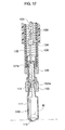
FIG. 17 is a front view of the distal end of the clip device when a clip having six arms is open;
FIG. 18 is a partially sectional plan view showing a clip of a second embodiment;
FIG. 19 is a partially sectional plan view showing a clip of a third embodiment;
FIG. 20 is a partially sectional plan view showing a clip of the third embodiment, when a clip connecting string is released from the clip;
FIG. 21 is a partially sectional plan view showing a clip of a fourth embodiment;
FIG. 22 is a partially sectional view showing a clip unit of a fifth embodiment;
FIG. 23 is a longitudinal sectional view of a distal end of the clip device of the fifth embodiment;
FIG. 24 is a longitudinal sectional view showing the distal end of the clip device when the clip is open, in the fifth embodiment;
FIG. 25 is a longitudinal sectional view showing the distal end of the clip device, when the clip is closed, in the fifth embodiment;
FIG. 26 is a longitudinal sectional view showing the distal end of the clip device, when the clip is closed, in a sixth embodiment;
FIG. 27 is a longitudinal sectional view of a distal end of the clip device of a seventh embodiment;
FIG. 28 is a longitudinal sectional view showing the distal end of the clip device when the clip is open, in the seventh embodiment;
FIG. 29 is a longitudinal sectional view showing the distal end of the clip device, when the clip is closed, in the seventh embodiment;
FIG. 30 is a longitudinal sectional view showing the distal end of the clip device when the clip is open, in an eighth embodiment;
FIG. 31 is a longitudinal sectional view showing the distal end of the clip device when the clip is open, in an ninth embodiment;
FIG. 32 is a longitudinal sectional view of a distal end of the clip device of a tenth embodiment;
FIG. 33 is a sectional view of a clip of the tenth embodiment, when open;
FIG. 34 is a sectional view of the clip of the tenth embodiment, when closed;
FIG. 35 is a sectional view of the clip of the tenth embodiment, when clamped;
FIG. 36 is a longitudinal sectional view of a distal end of the clip device of an eleventh embodiment;
FIG. 37 is a sectional view of a clip of the eleventh embodiment, when open;
FIG. 38 is a sectional view of the clip of the eleventh embodiment, when closed;
FIG. 39 is a sectional view of the clip of the eleventh embodiment, when clamped;
FIG. 40 is a longitudinal sectional view of a distal end of the clip device of a twelfth embodiment;
FIG. 41 is a partial perspective view of a base end portion of a clip of the twelfth embodiment;
FIG. 42 is a sectional view of the clip of the twelfth embodiment, when open;
FIG. 43 is a sectional view of the clip of the twelfth embodiment, when closed;
FIG. 44 is a sectional view of the clip of the twelfth embodiment, when clamped;
FIG. 45 is a longitudinal sectional view of a distal end of the clip device of a thirteenth embodiment;
FIG. 46 is a longitudinal sectional view of the clip device shown in FIG. 45, which is inserted in a treatment tool insert channel of an endoscope;
FIG. 47 is a longitudinal sectional view showing the distal end of the clip device when the clip is open, in the thirteenth embodiment;
FIG. 48 is a longitudinal sectional view showing the distal end of the clip device, when the clip is closed, in the thirteenth embodiment;
FIG. 49 is a longitudinal sectional view showing the clip when clamped;
FIG. 50 is a longitudinal sectional view of a distal end of the clip device of a fourteenth embodiment;
FIG. 51 is a longitudinal sectional view of a distal end of the clip device of a fifteenth embodiment;
FIG. 52 is a longitudinal sectional view showing the distal end of the clip device when the clip is open, in the fifteenth embodiment;
FIG. 53 is a longitudinal sectional view showing the distal end of the clip device, when the clip is closed, in the fifteenth embodiment;
FIG. 54 is a longitudinal sectional view showing the clip when clamped;
FIG. 55 is a longitudinal sectional view of a distal end of the clip device of a sixteenth embodiment;
FIG. 56 is a longitudinal sectional view of a distal end of the clip device of a seventeenth embodiment;
FIG. 57 is a longitudinal sectional view of a distal end of the clip device of an eighteenth embodiment;
FIG. 58 is a longitudinal sectional view of a distal end of the clip device of a nineteenth embodiment;
FIG. 59 is a partially sectional plan view of the clip unit of a twentieth embodiment;
FIG. 60 is a partially sectional plan view of the clip unit enclosed in a sterile pack;
FIG. 61 is a plan view showing that the sterile pack is partially open;
FIG. 62 is a longitudinal sectional view showing the clip unit before it is connected to a sheath unit;
FIG. 63 is a longitudinal sectional view showing an operation in which the clip unit is being connected to the sheath unit;
FIG. 64 is a longitudinal sectional view showing an operation in which the clip unit is being connected to the sheath unit, after the state shown in FIG. 63;
FIG. 65 is an external view showing a general construction of the clip device of a twenty-first embodiment;
FIG. 66 is a longitudinal sectional view of a distal end of the clip device, when the clip is open and engaged with notches, in the twenty-first embodiment;
FIG. 67 is a longitudinal sectional view of the distal end of the clip device, when the clip is closed, in the twenty-first embodiment;
FIG. 68 is a longitudinal sectional view of the distal end of the clip device, when the clip is open, in the twenty-first embodiment;
FIG. 69 is a longitudinal sectional view showing the clip when clamped, in the twenty-first embodiment;
FIG. 70 is a perspective view showing the distal end of the clip device of the twenty-first embodiment;
FIG. 71 is a longitudinal sectional view of the distal end of the clip device, when the clip is open, in a twenty-second embodiment; and
FIG. 72 is a perspective view showing the distal end of the clip device of the twenty-first embodiment.
DESCRIPTION OF THE PREFERRED EMBODIMENTS
The present invention will be described below with reference to the embodiments shown in the drawings.
FIG. 1 shows a general construction of a clip device, in which a clip 110 is disposed at a distal end of a flexible outer sheath (i.e., cover tube) 130 which is formed from tetra-fluorinated ethylene resin, super-elastic alloy, and so on.
A base end portion (not shown) of the clip 110 is housed in the distal end of the outer sheath 130, and arms 111, which are open in the drawing, and claw portions 112, which are bent inwardly at the tips of the arms 111, are exposed from the distal end of the outer sheath 130.
An operating unit 140 is connected to the outer sheath 130. In the operating unit 140, a slider 141 is connected to a tip of an operating wire 131 which will be described later, and is slidably provided to a shaft 142 which has a finger-ring 143 at an end thereof.
A base end cylinder 132 of the outer sheath 130 is slidably connected to the shaft 142, and is moved relative to the slider 141. Namely, the slider 141, the shaft 142, and the outer sheath 130 are independently moved from each other along the longitudinal axis of the outer sheath 130. A water supply tube 133 is projected from the base end cylinder 132 so that water can be supplied into the outer sheath 130 through the water supply tube 133.
FIG. 2 is a longitudinal sectional view in which the distal end of the outer sheath 130 is enlarged, and FIG. 3 is a front view of the end portion. Note that, in these drawings, the clip 110 which is closed, is almost completely housed in the outer sheath 130.
The clip 110 is integrally formed from stainless steel for a spring, for example. Namely, the clip 110 is obtained by bending the stainless steel plate, and the three arms 111 connected to the base end portion 113 are provided at equivalent angular intervals (i.e., approximately 120 degrees), and open and close without crossing each other.
Each of the arms 111 has an open-close deforming portion 114 located close to the base end portion 113. The open-close deforming portion 114 has a constriction 114 a and a bulge portion 114 b formed between the constriction 114 a and the base end portion 113. The bulge portion 114 b is bulged outward and formed in an arc shape in section. The arms 111 are open and closed by deforming the open-close deforming portion 114. Note that the shape of the bulge portion 114 b may be other than the arc shape, if the arms 111 can be open and closed.
The operating wire 131 is disposed in the axial position of the outer sheath 130. The operating wire 131 is operated by the slider 141 to move along the axis of the outer sheath 130. A clip connecting hook 134 is attached to the tip of the operating wire 131. A clip connecting string 115, which is connected to the base end portion 113 of the clip 110, can be engaged with and disengaged from the clip connecting hook 134. The clip connecting string 115 is a strand wire or a normal single wire made of stainless steel, for example.
The rear end half of the clip connecting hook 134 is connected to the operating wire 131 with solder and so on, and the clip connecting string 115 can be engaged with and disengaged from a recess 134 a formed on a side surface of the front end half of the clip connecting hook 134. The clip connecting string 115 is tied in a knot 115 a, which is engagable with the recess 134 a.
A clip open-close ring 120 is mounted in the outer sheath 130, so that the bulge portion 114 b of the clip 110 is pressed from the outside to deform the bulge portion 114 b. The clip open-close ring 120 is movable along the axial direction of the outer sheath 130 relative to the clip 110.
A core member 121, which is made of metal, for example, is provided inside the arms 111 of the clip 110. The core member 121 is extended from the open-close deforming portion 114 to the base end portion 113. The core member 121 has a small diameter portion 121 a positioned inside the constriction 114 a and a large diameter portion 121 b positioned closer to the base end portion 113 in comparison with the small diameter portion 121 a. Thus, the large diameter portion 121 b cannot pass through the constriction 114 a, to prevent the core member 121 from dropping off from the inside of the arms 111.
A base end portion of the clip open-close ring 120 is fit in a ring receiving cylinder 135, which is connected to a tip portion of an inner sheath 136. The inner sheath 136 is a coil pipe, which is tightly wound, and is connected to the shaft 142 of the operating unit 140 with solder, for example.
Thus, as shown in FIGS. 4 and 5, the clip 110 forms a single unit containing the clip connecting string 115, the clip open-close ring 120, and the core member 121. The clip connecting string 115 is passed between the base end portion 113 of the clip 110 and a rear end surface 121 c of the core member 121. The clip open-close ring 120 is fit on an outer surface of the base end portion 113 of the clip 110, and is fixed there with a frictional force.
When in use, as shown in FIG. 6, the tip portion of the inner sheath 136 is projected from the distal end of the outer sheath 130, and the clip connecting hook 134 is projected from the tip portion of the inner sheath 136. Then, as shown in FIG. 7, the knot 115 a of the clip connecting string 115 is engaged with the recess 134 a of the clip connecting hook 134. Note that the arms 111 are closed due to the clip open-close ring 120 being engaged with the base end portion 113. Then, maintaining the state in which the clip connecting string 115 is engaged with the clip connecting hook 134, as shown in FIG. 8, the operating wire 131 is pulled from the operating unit 140, so that the clip connecting hook 134 is retracted into the inner sheath 136.
As a result, as shown in FIG. 2, the clip open-close ring 120 is received by the ring receiving cylinder 135, so that the outer sheath 130 is moved forward relative to the clip 110, and the clip 110 is inserted and housed in the distal end of the outer sheath 130, in a state in which said arms are closed.
Keeping the state shown in FIG. 2, the outer sheath 130 is inserted into a treatment tool insert channel of an endoscope not shown. The knot 115 a of the clip connecting string 115 is preferably formed larger than the gap between the inner sheath 136 and the clip connecting hook 134 so that the clip connecting string 115 is disengaged from the clip connecting hook 134 during the inserting operation.
When the distal end of the outer sheath 130 is led to the diseased part to be clipped, as shown in FIG. 9, the outer sheath 130 is moved rearward (upward in the drawing), and the operating wire 131 is then pulled. As a result, the bulge portion 114 b of the clip 110 is pulled into the clip open-close ring 120, and is deformed, so that the arms 111 are open. In this state, although the constriction 114 a of the clip 110 is pressed inward, since the constriction 114 a is uniformly pressed onto the small diameter portion 121 a of the core member 121 as shown in FIG. 10, the three arms 111 can open widely at approximately 120-degree intervals, while maintaining stability.
Then, when the operating wire 131 is further pulled from the operating unit, as shown in FIG. 11, the opening parts of the arms 111 of the clip 110 are pulled into the clip open-close ring 120 and squeezed, so that the claw portions 112 formed at the tip portions of the arms 111 bite into a mucous membrane, enveloping the diseased portion M.
Therefore, as shown in FIG. 12, when the inner sheath 136 is slightly moved rearward (i.e., upward in the drawing), the ring receiving cylinder 135 is released from the clip open-close ring 120. At this time, as shown in FIG. 13, if the top surface of the clip connecting hook 134 is pressed onto the base end portion 113 of the clip 110, the ring receiving cylinder 135 is more easily released from the clip open-close ring 120.
Then, as shown in FIG. 14, when the inner sheath 136 is moved rearward to project the clip connecting hook 134 forward, the recess 134 a of the clip connecting hook 134 is exposed from the inner sheath 136. Accordingly, only by moving the clip connecting hook 134 properly, can the clip connecting hook 134 be disengaged from the clip connecting string 115. Thus, the clip 110, in which the arms 111 are kept in the closed condition by the clip open-close ring 120, is clamped on the diseased portion M.
As described above, in the first embodiment, the core member 121 is provided inside the clip 110 and is in contact with an inner surface of the open-close deforming portion 114 at least when the arms 111 are open, and the open-close ring 120 is operated by remote control performed from the base end of the outer sheath 130, which is opposite to the distal end. The open-close ring 120 is engaged with the open-close deforming portion 121 to open and close the arms 111 with a substantially equivalent angular interval and so as to prevent the arms 111 from crossing each other. Therefore, the arms 110 are stably opened and closed to perform tasks such as stopping bleeding, ligation, and marking in a human body.
Note that the number of arms 111 of the clip 110 is not restricted to three, there can be two or more as shown in FIGS. 15, 16, and 17.
FIG. 18 shows a second embodiment, in which both ends of the clip connecting string 115 are bundled in a pipe 116, for example, which adheres to the ends, to form a ring, instead of tying the ends as in the first embodiment. It is preferable that the outer diameter of the pipe 116 is greater than the gap between the inner sheath 136 and the clip connecting hook 134 to prevent the clip connecting string 115 from releasing from the clip connecting hook 134 during the inserting operation.
FIGS. 19 and 20 show a third embodiment, in which the clip connecting hook 134 has an acute angle corner 134 b, which is firmly pressed onto the clip connecting string 115 to cut the string 115. Therefore, due to a series of operations in which the operating wire 131 is pulled toward the operating unit 140 step by step, the engagement of the clip connecting hook 134 and the clip connecting string 115 is released, at the last stage of the operation. Thus, the clip connecting string 115 comes off from the clip 110, as shown in FIG. 20, and is recovered with the clip connecting hook 134.
FIG. 21 shows a fourth embodiment in which the acute angle corner 134 b is formed on the clip connecting hook and the ends of the clip connecting string 115 are tied in a knot 115 a.
According to the second through fourth embodiments, the same effect as the first embodiment can be obtained.
With reference to FIGS. 22 through 26, a fifth embodiment is described below, in which a cutting mechanism is provided for cutting the clip connecting string 115. The parts which correspond to those in the to the above described embodiments are indicated by the same references as those of the above described embodiments.
FIG. 22 shows a clip unit containing the clip 110, the clip connecting string 115, the clip open-close ring 120, and the core member 121. FIG. 23 shows a state in which the clip unit is housed in the outer sheath 130. Ends of the clip connecting string 115 are bundled and combined in the pipe 116 in a similar way to that in the second embodiment shown in FIG. 18.
The clip connecting string 115 is passed through a string passing hole 121 d formed in a portion close to the base end of the core member 121, and is engaged with the base end portion 113. The string passing hole 121 d is inclined by 45 degrees, for example, relative to the longitudinal axis of the core member 121, so that a string cutting edge 122 is formed at an end opening of the string passing hole 121 d. Namely, when the clip connecting string 115 is strongly pulled rearward (upward in the drawing), the clip connecting string 115 is cut by the string cutting edge 122. The other constructions are identical with those of the above described embodiments.
In the usage of the clip device, while the clip 110 is housed in the outer sheath 130 as shown in FIG. 23, the distal end of the outer sheath 130 is led to the diseased part to be clipped. Then, as shown in FIG. 24, the outer sheath 130 is moved rearward (upward in the drawing), and the operating wire 131 is then pulled, so that the arms 111 are open. After this, when the operating wire 131 is further pulled from the operating unit, as shown in FIG. 25, the arms 111 are pulled into the clip open-close ring 120 and squeezed, so that the claw portions 112 bite into the mucous membrane of the diseased portion M.
When the operating wire 131 is further pulled from the operating unit, the clip connecting string 115 is cut by the string cutting edge 122. Therefore, when the clip connecting string 115 is pulled rearward together with the inner sheath 136, the ring receiving cylinder 135 is separated from the clip open-close ring 120, and the clip 110 is released from the clip connecting string 115.
Thus, the clip 110, in which the arms 111 are closed by the clip open-close ring 120, is clamped on the diseased portion M.
As described above, in the fifth embodiment, the cutting mechanism containing the string cutting edge 122 is provided close to the clip 110, and the clip connecting string 115 is surely cut, so that the clipping operation is smoothly performed.
FIG. 26 shows a sixth embodiment, in which a string cutting edge 116 is provided to a portion of the clip 110 between the base end portion 113 and the arms 111. The operation and effects of the clip device of the sixth embodiment are the same as those of the fifth embodiment.
With reference to FIGS. 27 through 29, a seventh embodiment is described below, in which a cylindrical recess 121 e is formed on an outer surface of the core member 121 so as to reduce interference between the clip 110 and the core member 121 when the clip 110 opens and closes. The parts which correspond to those in the previously described embodiments are indicated by the same references.
The cylindrical recess 121 e is formed by making part of the large diameter portion 121 b approximately the same diameter as that of the small diameter portion 121 a. The bulge portion 114 b of the open-close deforming portion 114 is formed not in an arc shape in section, as in the first embodiment, but in a bottle-like shape. The bulge portion 114 b has a first bent portion 114 c, which is bent outwardly at an obtuse angle, and a second bent portion 114 d, which is inwardly bent at an obtuse angle.
In the usage of the clip device, while the clip 110 is housed in the outer sheath 130 as shown in FIG. 27, the distal end of the outer sheath 130 is led to the diseased part to be clipped. Then, as shown in FIG. 28, the outer sheath 130 is moved rearward, and the operating wire 131 is then pulled, so that the bulge portion 114 b is pulled into the clip open-close ring 120 and is deformed, to open the arms 111. After this, when the operating wire 131 is further pulled from the operating unit, as shown in FIG. 29, the arms 111 are pulled into the clip open-close ring 120 and squeezed, so that the claw portions 112 bite into the mucous membrane of the diseased portion M.
In the open-close operation of the clip 110, the bulge portion 114 b is pressed inward by the open-close ring 120, so that the second bent portion 114 d is pushed inward to deform toward the core member 121. However, the cylindrical recess 121 e (i.e., a frictional resistance reducing portion) is formed to prevent the clip 110 from interfering with the core member 121. Therefore, the second bent portion 114 d is not pressed on the core member 121 with a large force, only a small frictional resistance is generated between the core member and the clip 110, and between the clip 110 and the clip open-close ring 120. Accordingly, the clip 110 is smoothly opened and closed with a small operating force.
The other operation and effects of the clip device of the seventh embodiment are the same as those of the previously described embodiments.
FIG. 30 shows an eighth embodiment, in which the cylindrical recess 121 e is continued to the small diameter portion 121 a. The operation and effects of the clip device of the eight embodiment are the same as those of the seventh embodiment.
FIG. 31 shows a ninth embodiment, in which the cylindrical recess is not provided, as in the seventh and eight embodiments. In the ninth embodiment, the thickness of a part of the clip 110 is less than the other portions so as to reduce frictional resistance. The thin portion 114 e is in contact with the core member 121 or the clip open-close ring 120, when the clip 110 opens and closes.
With reference to FIGS. 32 through 35, a tenth embodiment is described below. In the drawings, the parts which correspond to those in the previously described embodiments are indicated by the same references.
In the tenth embodiment, as shown in FIG. 32, the clip 110, to which no external force applies, is substantially housed in the outer sheath 130. The clip 110 has a pair of arms 111, and in FIG. 32, the arms 111 are parallel to each other.
The clip 110 is formed from a single plate member, such as stainless steel for a spring, and has a pair of arms 111, which are parallel in the neutral condition, and a base end portion 113, to which the arms 111 are connected. The base end portion 113 is annular and extends in approximately 360 degrees. The tips of the arms 111 are inwardly bent to form claw portions 112.
The clip 110 is obtained by bending the plate member without crossing at any portion in such a manner that a boundary portion 117, between the base end portion 113 and the arms 111, is formed in a constricted shape. Namely, the plate member is bent at the boundary portion 117 in such a manner that the plate member is projected toward the inside of the boundary portion 117. Thus, the plate member has peak portions, which are projected toward the inside of the boundary portion 117 and are in contact with each other.
The clip 110, constructed as described above, does not have to be provided with a portion where the breadth is narrow, not even in the boundary portion 117. Namely, the clip 110 has a substantially uniform breadth as a whole. Therefore, the clip 110 has no weak portion, so that the clip 110 cannot be accidentally damaged or deformed while handling. Note that the claws 112 can be made thin or narrow, which does not affect the strength of the clip.
The operating wire 131 is disposed in the axial position of the outer sheath 130, and is operated by the slider 141 to move along the axis of the outer sheath 130. A connecting member 137 is fixed to the tip portion of the operating wire 131, and a clip connecting hook 134 is connected to the connecting member 137. The clip 110 can be engaged with and disengaged from the clip connecting hook 134.
The tip portion 134 c of the clip connecting hook 134 has a greater diameter than the other portions thereof. A slot 134 d, extending along the axis of the clip connecting hook 134, is formed therein to transverse the tip portion 134 c. A connecting hole 113 a is formed in the base end portion 113, and the tip portion 134 c is engaged with the connecting hole 113 a, so that the clip 110 is connected to the clip connecting hook 134. Thus, by elastically deforming the clip connecting hook 134 into the narrowing slot 134 d, the clip connecting hook 134 can be released from the clip 110.
A clip open-close ring 120, for deforming the base end portion 113, is mounted in the outer sheath 130. An inner wall of a base end portion 120 a of the clip open-close ring 120 is cylindrical, and has a diameter less than the other portion of the clip open-close ring 120. The base end portion 113 of the clip 110 is deformed by engaging with an inner wall of the clip open-close ring 120.
The other constructions are identical with those of the previously described embodiments.
An operation of the tenth embodiment is as follows. First, the outer sheath 130 is inserted into a treatment tool insert channel of an endoscope not shown, and keeping a state in which the clip 110 is projected from the outer sheath 130, the clip open-close ring 120 is pushed out toward the clip 110, by pulling the operating wire 131.
As a result, as shown in FIG. 33, the base end portion 113 is pulled into the clip open-close ring 120, and deformed, so that the arms 111 are open.
Maintaining this condition, the distal end of the outer sheath 130 is positioned in such a manner that the diseased portion M lies between the arms 111. After that, when the clip open-close ring 120 is pushed out toward the clip 110, as shown in FIG. 34, the tip portion of the clip open-close ring 120 presses the arms 111 while the base end portion 113 is further deformed, so that the arms 111 become parallel to each other, and the claw portions 112 bite into a mucous membrane of the diseased portion M.
The base end portion 113 of the clip 110 is pulled into the base end portion 120 a of the clip open-close ring 120, and is squeezed or deformed by the clip open-close ring 120. Due to this, the clip connecting hook 134 is pressed, so that the clip connecting hook 134 can pass through the connecting hole 113 a.
Thus, the clip connecting hook 134 is released from the clip 110, and the outer sheath 130 is removed from the diseased portion M. Thus, as shown in FIG. 35, the clip 110 to which the clip open-close ring 120 is attached, remains clamping on the mucous membrane of the diseased portion M.
As described above, according to the tenth embodiment, since the clip 110 has a uniform breadth along any portion thereof, there is no weak portion, and thus, the clip 110 cannot be accidentally damaged or deformed during handling.
With reference to FIGS. 36 through 39, which correspond to FIGS. 32 through 35 of the tenth embodiment, respectively, an eleventh embodiment is described below. In the drawings, the parts which correspond to those in the previously de-scribed embodiments are indicated by the same references.
In the eleventh embodiment, the difference from the tenth embodiment is the shape of the claw portions 112, which are bent inward with an acute angle (i.e., the angle θ is less than 90 degrees). The angle θ can be between 30 degrees and 60 degrees. The other constructions are identical with those of the tenth embodiment.
Although the operation of the eleventh embodiment is basically the same as that of the tenth embodiment, the merit of the eleventh embodiment is that the claw portions 112 more firmly bite into mucous membrane of a diseased portion M, in comparison with the tenth embodiment, since the claw portions 112 are engaged with the mucous membrane in a hook-like manner. Therefore, the clip 110 does not come off the diseased portion M easily.
Note that, if the angle θ is close to 90 degrees, the claw portions 112 may easily come off the mucous membrane M, and if the angle θ is close to 0 degrees, the claw portions 112 hardly bite into the mucous membrane M. If the angle θ is from 30 to 60 degrees, the claw portions 112 easily bite into the mucous membrane M, and do not come off easily.
With reference to FIGS. 40 through 44, a twelfth embodiment is described below. In the drawings, the parts which correspond to those of the previously described embodiments are indicated by the same references.
In the twelfth embodiment, the clip connecting hook 134 has an upper hook portion 134 e and a lower hook portion 134 f. The upper hook portion 134 e is engaged with the connecting member 137 connected to the tip of the operating wire 131. The base end portion 113 of the clip 110 is detachably engaged with the lower hook portion 134 f. A pair of stoppers 118 is provided to the base end portion 113. As shown in FIG. 41, each of the stoppers 118 is formed by cutting a part of the base end portion 113, and is extended outward from the base end portion 113 to function as a flat spring. The clip open-close ring 120 is a cylindrical member in which a small diameter portion is not provided, as in the eleventh embodiment (see FIG. 36, for example).
The other constructions are identical with those of the eleventh embodiment.
The operation of the twelfth embodiment is as follows. First, the clip 110 is projected from the outer sheath 130, and the clip open-close ring 120 is then pushed out toward the clip 110, by pulling the operating wire 131. Due to this, as shown in FIG. 42, the base end portion 113 is pulled into the clip open-close ring 120, and deformed, so that the arms 111 are open. At this time, the stoppers 118 are engaged with an inner wall of the clip open-close ring 120, so that the stoppers 118 are deformed and squeezed.
Keeping this condition, the distal end of the outer sheath 130 is positioned in such a manner that the diseased portion M lies between the arms 111. After that, when the clip open-close ring 120 is pushed out toward the clip 110, as shown in FIG. 43, the tip portion of the clip open-close ring 120 presses the arms 111 while the base end portion 113 is further deformed, so that the arms 111 become parallel to each other, and the claw portions 112 stick into the mucous membrane of the diseased portion M. At the same time, the stoppers 118 are projected from the upper end of the clip open-close ring 120.
Then, the clip connecting hook 134 is disengaged from the base end portion 113, and is moved upward in FIG. 43, so that the clip 110, in which the arms 111 are kept in the closed condition by the clip open-close ring 120, remains at the diseased portion M after being clamped, as shown in FIG. 44.
In this clamping condition, since the stoppers 118 are engaged with the upper end of the clip open-close ring 120, the clip open-close ring 120 is prevented from disengaging from the clip 110. Accordingly, even if an external force is applied to the clip open-close ring 120, the clip open-close ring 120 is not released from the clip 110, and therefore, the clip 110 does not come off the diseased portion M.
As described above, according to the twelfth embodiment, when the clip open-close ring 120 is engaged with the clip 110, the engaging condition is maintained by the stoppers 118. Therefore, the clip is held closed, so that the clip 110 does not easily come off the diseased portion M because of an external force.
With reference to FIGS. 45 through 49, a thirteenth embodiment is described below. In the drawings, the parts which correspond to those in the previously described embodiments are indicated by the same references.
In the thirteenth embodiment, the clip open-close ring 120 is a coil pipe, which is obtained by tightly winding stainless steel wire at a constant diameter. The base end portion 113 of the clip 110 is pulled into the clip open-close ring 120, and is pressed to deform from a circular shape to an oval shape in section.
The clip device of the thirteenth embodiment is inserted into a treatment tool insert channel 150 of an endoscope, and as shown in FIG. 46, the clip device passes through a bending portion of the treatment tool insert channel 150, in which the clip open-close ring 120 is bent with the clip connecting string 115 and the outer sheath 130.
Thus, in the distal portion of the clip device, the only hard portion, which will not bend freely, is the clip 110. Therefore, even when the treatment tool insert channel 150 is bent with a considerably small radius of curvature, the clip device can smoothly pass through the treatment tool insert channel 150.
When the distal end of the clip device is projected from the distal end of the treatment tool insert channel 150 to the inside of a human body, the outer sheath 130 is slightly pulled to the operating unit 140 so that the clip 110 is projected from the distal end of the outer sheath 130, and the operating wire 131 is then pulled toward the operating unit 140.
Thus, the base end portion 113 of the clip 110 is pulled into the clip open-close ring 120, to deform from a circular shape to an oval shape, so that the pair of arms 111 are opened.
While maintaining this condition, the distal end of the outer sheath 130 is positioned in such a manner that the diseased portion M lies between the arms 111. Then, when the operating wire 131 is further pulled toward the operating unit 140, the clip open-close ring 120 pushes the arms 111, so that the arms 111 become parallel to each other, and the claw portions 112 bite into the mucous membrane of the diseased portion M, as shown in FIG. 48.
Then, the outer sheath 130 is laterally moved while the operating wire 131 is slightly pushed to the distal end, so that the engagement between the clip connecting string 115 and the clip open-close hook 134 is loosened. Therefore, when the distal end of the outer sheath 130 is properly moved, the clip 110 is disengaged from the outer sheath 130 while biting into the mucous membrane of the diseased portion M. The clip is kept closed by the clip open-close ring 120. Thus, the clip 110 is clamped there as shown in FIG. 49.
As described above, according to the thirteenth embodiment, since the clip open-close ring 120 is formed from a flexible cylindrical body such as a coil pipe, the hard non-bending portion of the distal end of the clip device is shortened, and therefore, even when the treatment tool insert channel 150 is bent with a considerably small radius of curvature, the clip device can smoothly pass through the treatment tool insert channel 150 without being damaged.
FIG. 50 shows a fourteenth embodiment, in which the clip open-close ring 120 is a cylindrical body made of rubber having elasticity. According to this embodiment, the same effect as the thirteenth embodiment is obtained.
With reference to FIGS. 51 through 54, a fifteenth embodiment is described below. The general construction is basically the same as that shown in FIG. 1. In the drawings, the parts which correspond to those in the previously described embodiments are indicated by the same references.
Note that the basic construction of the fifteenth embodiment is the same as the eleventh embodiment shown in FIGS. 36 through 39, except that a water supply passage 160 is provided in the outer sheath 130 and a temporal-fixing agent is filled in the clip open-close ring 120. The other constructions are the same as those in the eleventh embodiment.
Water is supplied into the outer sheath 130 through a syringe, for example, attached to the water supply tube 133 (see FIG. 1). The base end cylinder 132 is sealed so that water supplied from the water supply tube 133 does not leak out through the base end cylinder 132.
A temporal-fixing agent T, composed of tackiness agent and so on, having a low tackiness, such as silicone system tackiness agent, is filled in the clip open-close ring 120. Due to this, the clip 110, the clip connecting hook 134, and the clip open-close ring 120 are integrally temporally fixed to each other.
The inner sheath 136 is loosely inserted in the outer sheath 130 over the whole length thereof. The space between the outer surface of the inner sheath 136 and the inner surface of the outer sheath 130 defines the water supply passage 160, through which water supplied from the water supply tube 133 passes.
The water supplied from the water supply tube 133 passes outside the clip open-close ring 120, and spouts out from the distal end of the outer sheath 130. At this time, since the water pressure does not act on the temporal-fixing agent T, the temporal fixing condition of the clip 110, the clip connecting hook 134, and the clip open-close ring 120 is not loosened.
The operation of the fifteenth embodiment is as follows. First, the outer sheath 130 is inserted into a treatment tool insert channel of an endoscope not shown, and while maintaining the state in which the clip 110 is projected from the outer sheath 130, the clip open-close ring 120 is pushed out toward the clip 110, by pulling the operating wire 131.
As a result, as shown in FIG. 52, the base end portion 113 is pulled into the clip open-close ring 120, and deformed, so that the arms 111 are open. At the same time, the temporal-fixing agent T is pushed out, to some extent from the inside of the clip open-close ring 120.
While maintaining this condition, the distal end of the outer sheath 130 is positioned in such a manner that the diseased portion M lies between the arms 111. At this time, if the target diseased portion cannot be recognized visually because of bleeding and so on, irrigating water is supplied through the water supply tube 133, while directing the distal end of the outer sheath 130 to the target. Thus, the irrigating water spouts out from the outer sheath 130, so that the blood and so on can be washed away while maintaining the state in which the clip 110 is temporarily fixed to the clip connecting hook 134, and the clip open-close ring 120.
Then, when the clip open-close ring 120 is pushed out toward the clip 110, as shown in FIG. 53, the base end portion 113 is further deformed, and the tip of the clip open-close ring 120 presses the rear surfaces of the arms 111. Due to this, almost all of the temporal-fixing agent T is pushed out from the clip open-close ring 120, and the arms 111 become parallel to each other, so that the claw portions 112 bite into the mucous membrane of the diseased portion M.
The base end portion 113 of the clip 110 is fit in the base end portion 120 a of the clip open-close ring 120, and is squeezed or deformed by the clip open-close ring 120. Due to this, the clip connecting hook 134 is pressed, so that the clip connecting hook 134 can pass through the connecting hole 113 a.
Thus, the clip connecting hook 134 is released from the clip 110, and the outer sheath 130 is removed from the diseased portion M. Thus, as shown in FIG. 54, the clip 110 to which the clip open-close ring 120 is attached, is clamped to the mucous membrane of the diseased portion M.
As described above, according to the fifteenth embodiment, the water supply passage 160 is formed in such a manner that the water supply passage 160 does not interfere with the temporal-fixing agent T. Accordingly, water is supplied from the distal end of the outer sheath 130 to perform irrigation of the bleeding are and to aid clamping, without shaking the clip 110, which is temporarily fixed with the temporal-fixing agent T.
FIG. 55 shows a sixteenth embodiment, in which the outer sheath 130 is a so called multi-lumen tube. Namely, the outer sheath 130 is divided into two parts, and one of the parts is the water supply passage 160, while the inner sheath 136, and the other elements are housed in another part.
FIG. 56 shows a seventeenth embodiment, in which the pitch of a part of the coil of the clip open-close ring 120 is made coarser at a portion close to the distal end of the inner sheath 136, in comparison with the other part, so that the water supply passage 160 is formed.
FIG. 57 shows an eighteenth embodiment, in which a hole is formed in each of the clip open-close ring 120 and the ring receiving cylinder 135 to enable communication between the inside of the clip open-close ring 120 and the ring receiving cylinder 135, and the outside of the clip open-close ring 120 and the ring receiving cylinder 135. Thus, the hole is the water supply passage 160, through which water passing through the inner sheath 136 is supplied to the outside of the clip open-close ring 120 and is spouted out from the distal end of the outer sheath 130.
FIG. 58 shows a nineteenth embodiment, in which the clip open-close ring 120 is formed with a passage in which the temporal-fixing agent T is not filled, the passage functions as the water supply passage 160. In this embodiment, the irrigating water supplied is spouted out from the outer sheath 130, while the temporal-fixing agent T is kept in the clip open-close ring 120.
As described above, according to the sixteenth through nineteenth embodiments, the same effect as the fifteenth embodiment is obtained.
With reference to FIGS. 59 through 64, a twentieth embodiment is described below. The general construction of the clip device is basically the same as that shown in FIG. 1. In the drawings, the parts which correspond to those in the previously described embodiments are indicated by the same references.
FIG. 59 shows a clip unit 200, which has the clip 120, the clip open-close ring 120, the clip connecting string 115, and the core member 121. The construction of the clip unit 200 is identical with that of the first embodiment shown in FIG. 5.
When the clip unit 200 is shipped to a user, the clip unit 200 is enclosed in a sterile pack 201, which is sealed along an enclosed portion 202 provided along the outer periphery of the sterile pack 201, as shown in FIG. 60. The enclosed portion 202 is easily opened at an easy open flap 203 at a corner of the sterile pack 201. In the sterile pack 201, the clip unit 200 is housed in a preserving member 204, which is a cylindrical member made of synthetic resin such as tetrafluoroethylene resin, or metal, and the clip unit 200 and the preserve member 204 have been sterilized.
Therefore, the clip unit 200 enclosed in the sterile pack 201 is not deformed nor damaged even if they are handled carelessly. The preserve member 204 has a slit 205, and the clip connecting string 115 extends to the outside of the preserve member 204, being sandwiched by the slit 205.
When the clip unit 200, enclosed in the sterile pack 201, is to be used, as shown in FIG. 61, the easy open flap 203 is pealed back by the fingers to open the sterile pack 201. Then, the clip unit 200 housed in the preserve member 204 is taken out of the sterile pack 201, and the clip connecting string 115 extending through the slit 205 is engaged with the clip connecting hook 134 provided to a sheath portion 170, as shown in FIG. 62.
The sheath portion 170 is constructed in such a manner that the inner sheath 136 is inserted or disposed in the flexible outer sheath 130, which is formed with roughly the same diameter as that of the preserve member 204, and the clip connecting string 115 is connected to the tip portion of the operating wire 131. The ring receiving cylinder 135 for receiving the clip open-close ring 120 is attached to the distal end of the inner sheath 136.
Then, as shown in FIG. 63, the operating wire 131 is pulled into the inner sheath 136 by an operation performed with the operating unit 140 (see FIG. 1), and at the same time, the preserve member 204 is fit to the outside of the inner sheath 136.
After this, as shown in FIG. 64, when the outer sheath 130 is moved forward (downward in the drawing), the preserve member 204 is pushed out by the outer sheath 130 to move relative to the clip unit 200 along the axial direction of the preserve member 204 and disengage from the clip 110, so that the clip 110 is set to a usable state. Thus, the preserve member 204 may have an opening at least at an upper end 204 a.
According to the twentieth embodiment, the clip unit 200 is housed in the preserve member 204, and is enclosed in the sterile pack 201, which can be opened using the easy open flap 203. Therefore, the clip unit 200 cannot be deformed until the clip unit 200 is attached to the sheath portion 170, even if the clip unit 200 enclosed in the sterile pack 201 is carelessly handled. Namely, the clip unit 200 can be used when it is needed.
With reference to FIGS. 65 through 70, a twenty-first embodiment is described below. The general construction of the clip device is basically the same as that of the tenth embodiment shown in FIGS. 32 through 35, except for the outer sheath 130. In the drawings, the parts which correspond to those in the previously described embodiments are indicated by the same references.
FIG. 65 shows a general construction of the clip device of the twenty-first embodiment, which is basically the same as that of the first embodiment shown in FIG. 1, except that notches 181 are formed at the distal end of the outer sheath 130. The notches 181 open to the distal end of the outer sheath 130 so that the arms 111 of the clip 110 can be open and closed.
The outer sheath 130 can be rotated about the axis thereof, while the arms 111 are engaged with the notches 181. Namely, the clip 110 can be rotated about the axis by rotating the outer sheath 130, and the arms 111 are open and closed by moving the outer sheath 130 along the axis relative to the slider 141.
FIG. 66 shows a distal end of the clip device. The construction of the distal end is basically the same as that in the tenth embodiment shown in FIG. 32, except for the notches 181. In the drawing, the arms 111 are open, and no external force applies on the arms 111.
The operation of the twenty-first embodiment is as follows. First, the outer sheath 130 is inserted into a treatment tool insert channel of an endoscope not shown, while keeping the state shown in FIG. 67, in which the arms 111 are housed in the outer sheath 130 and closed. Then, the outer sheath 130 is pulled to the operating unit 140, so that the clip 110 is projected from the outer sheath 130, and the operating wire 131 is pulled to the operating unit 140. As a result, as shown in FIG. 68, the base end portion 113 of the clip 110 is pulled into the clip open-close ring 120, so that the base end portion 113 is deformed to open the arms 111.
Maintaining this condition, the distal end of the outer sheath 130 is positioned in such a manner that the diseased portion M lies between the arms 111, and the operating wire 131 is then further pulled to the operating unit 140. Due to this, as shown in FIG. 69, the tip portion of the clip open-close ring 120 presses the arms 111 while the base end portion 113 is further deformed, so that the arms 111 become parallel to each other, and the claw portions 112 bite into the mucous membrane of the diseased portion M.
The base end portion 113 of the clip 110 is fit in the base end portion 120 a of the clip open-close ring 120, and is squeezed or deformed by the clip open-close ring 120, so that the clip connecting hook 134 can be released from the clip 110. Thus, the clip 110 is clamped to the mucous membrane of the diseased portion M.
In the clipping operation described above, if the rotational position of the clip 110 about the axis is to be changed when the clip 110 is open as shown in FIG. 68, the outer sheath 130 is moved toward the distal end relative to the inner sheath 136. Thus, the notches 181 formed on the distal end of the outer sheath 130 are engaged with the arms 111 of the clip 110 as shown in FIG. 70. The base end cylinder 132 or the outer sheath 130 is then rotated as shown in FIGS. 65 and 66, so that the clip 110, engaged with the notches 181, is rotated about the axis as shown by the arrow D in FIG. 66.
The ability of the outer sheath 130 to rotate the clip is superior to that of a wire and so on. Therefore, even when the inner sheath 136 is bent, the rotational movement of the base end cylinder 132 is transmitted to the notches 181.
Therefore, in any conditions, the angular position of the clip 110 about the axis can be controlled arbitrarily, so that the clip 110 can be set to the most preferable direction to bite into the diseased portion T. Further, by engaging the notches 181 with the clip 110, the clip 110 is prevented from rotating accidentally.
FIGS. 71 and 72 show a twenty-second embodiment, in which the number of arms 111 is three, and the notches 181 are formed in three portions at the distal end of the outer sheath 130. Further, the operating wire 131 and the clip 110 are connected by the clip connecting string 115. The other constructions are the same as those of the twenty-first embodiment.
In the first through twenty-second embodiments, the number of the arms 111 is not restricted to two or three as shown in the corresponding drawings, but can be changed.
Further, in the fifth, sixth, eleventh through twenty-second embodiments, when the number of the arms 111 is two, the clip may be obtained by bending a metal plate strip, such as a stainless steel strip, in an α-shape.
Although the embodiments of the present invention have been described herein with reference to the accompanying drawings, obviously many modifications and changes may be made by those skilled in this art without departing from the scope of the invention.
The present disclosure relates to subject matter contained in Japanese Patent Application Nos. 2001-153658, 2001-154804, 2001-177831, 2001-184360, 2001-247927, 2001-249834, 2001-343985, 2001-346965, 2001-349642, and 2001-353218 (filed on May 23, May 24, Jun. 13, Jun. 19, Aug. 17, Aug. 21, Nov. 9, Nov. 13, Nov. 15, and Nov. 19, 2001, respectively), which are expressly incorporated herein, by reference, in their entireties.