US6993798B1 - Method and apparatus for leveling a transportable bed assembly - Google Patents
Method and apparatus for leveling a transportable bed assembly Download PDFInfo
- Publication number
- US6993798B1 US6993798B1 US10/630,491 US63049103A US6993798B1 US 6993798 B1 US6993798 B1 US 6993798B1 US 63049103 A US63049103 A US 63049103A US 6993798 B1 US6993798 B1 US 6993798B1
- Authority
- US
- United States
- Prior art keywords
- mattress
- expandable
- mattress support
- support member
- gaseous fluid
- Prior art date
- Legal status (The legal status is an assumption and is not a legal conclusion. Google has not performed a legal analysis and makes no representation as to the accuracy of the status listed.)
- Expired - Fee Related, expires
Links
Images


Classifications
-
- B—PERFORMING OPERATIONS; TRANSPORTING
- B60—VEHICLES IN GENERAL
- B60P—VEHICLES ADAPTED FOR LOAD TRANSPORTATION OR TO TRANSPORT, TO CARRY, OR TO COMPRISE SPECIAL LOADS OR OBJECTS
- B60P3/00—Vehicles adapted to transport, to carry or to comprise special loads or objects
- B60P3/32—Vehicles adapted to transport, to carry or to comprise special loads or objects comprising living accommodation for people, e.g. caravans, camping, or like vehicles
- B60P3/36—Auxiliary arrangements; Arrangements of living accommodation; Details
- B60P3/38—Sleeping arrangements, e.g. living or sleeping accommodation on the roof of the vehicle
-
- A—HUMAN NECESSITIES
- A47—FURNITURE; DOMESTIC ARTICLES OR APPLIANCES; COFFEE MILLS; SPICE MILLS; SUCTION CLEANERS IN GENERAL
- A47C—CHAIRS; SOFAS; BEDS
- A47C17/00—Sofas; Couches; Beds
- A47C17/64—Travelling or camp beds
- A47C17/80—Travelling or camp beds adapted to be used in or connected to vehicles
-
- A—HUMAN NECESSITIES
- A47—FURNITURE; DOMESTIC ARTICLES OR APPLIANCES; COFFEE MILLS; SPICE MILLS; SUCTION CLEANERS IN GENERAL
- A47C—CHAIRS; SOFAS; BEDS
- A47C19/00—Bedsteads
- A47C19/04—Extensible bedsteads, e.g. with adjustment of length, width, height
- A47C19/045—Extensible bedsteads, e.g. with adjustment of length, width, height with entire frame height or inclination adjustments
Definitions
- the invention relates to an adjustable mattress support arrangement for adjustably supporting a mattress in the cab of a vehicle such as a truck. More specifically, the invention relates to an arrangement which utilizes expandable air cushions positioned between a rectangularly shaped mattress and a truck cab floor generally at each of the four corners of the rectangularly shaped mattress support member with said member in turn being comprised of pivotally connected first and second sections.
- It is yet another object of the invention is to provide a mattress support member which has pivotally connected front and rear sections wherein said sections may be folded for storage convenience or unfolded to form a sleeping accommodation.
- a sleeping surface such as a mattress supported by a mattress support system may be adjusted at multiple points to provide a level or otherwise comfortable sleeping combination.
- a case in point would be the situation encountered by most over-the-road (OTR) transport vehicles such as tractor trailer rigs.
- OTR over-the-road
- tractor trailer rigs the cab portion (tractor) typically provides for space for sleeping accommodation behind the driver's/passengers' seating area.
- level parking surface may not always be available to the tractor/trailer operator, the operator typically finds him or herself facing the situation wherein the truck is on uneven ground or, more specifically, presents an angled orientation which does not lend itself to a comfortable sleeping position.
- the instant invention addresses the deficiency in the prior art by disclosing and claiming a mattress support system which allows for at least four points of individual adjustment. This adjustment is facilitated by a valving means which is attached to the tractor trailer compressed air supply and each of a plurality of expandable cushion means such as bellows.
- the bellows are placed typically in the general area of the corners of the mattress support member and the truck floor to allow the operator to individually adjust each expandable cushion to a desired height thus facilitating a level or otherwise comfortable sleeping surface for the individual operator.
- Various leveling devices though deficient, have been disclosed in the prior art.
- Phillips U.S. Pat. No. 2,070,960 relates to fluid hoists or jacks of a small compact, portable fluid jack of relatively great power so as to easily lift an automobile by means of a tire pump or compressed air available in most service stations, and which jack is also adapted for use in combination with the large hydraulic or air hoists in common use in service stations for subsequent lifting of the weight from the springs of an automobile after the automobile has been elevated by the large hydraulic jack.
- Nunlist U.S. Pat. No. 2,769,182 discloses an apparatus for lifting selected portions of a mattress and more particularly to an inflatable mattress lifter.
- Bayerkohler (U.S. Pat. No. 2,804,118) relates to improvements in pneumatic jacks for straightening automobile body parts especially although not necessarily.
- the primary object of the invention is to provide a pneumatic jack of the bellows type adapted for use in straightening automobile bodies and fenders where, because of space limitations, it is impossible to use other types of jacks.
- Aymar (U.S. Pat. No. 3,392,412) relates to a bedrest which may be conveniently placed under a mattress for raising and lowering a portion of the mattress, such as the portion constituting the head and backrest of the user, or the portion upon which his feet are located.
- Scott U.S. Pat. No. 3,426,373 discloses an inflatable under-mattress comprises a base member having at each longitudinal side thereof an inflatable chamber.
- the chambers are independently inflatable.
- Each chamber is so shaped that when inflated the upper surface thereof is inclined downwardly towards the center of the under-mattress.
- Each chamber has one longitudinal side extending along the length of the under-mattress along one side thereof. The other side of each chamber is so shaped as to increase the width of the chamber from the foot end to the head end of the under-mattress.
- Aymar U.S. Pat. No. 3,606,623 discloses a bellows assembly for a pneumatically operated adjustable bedrest is provided with integral channel means whereby pressurized air is introduced into what will ultimately be the wider end of the inflated bellows and is then channeled down into the opposed end or apex of the V-shaped bellows. From the apex the pressurized air is then free to move into the separate chambers defined by the channels and the adjacent confronting layers of the bellows. This provides a mechanical advantage which permits smooth elevating action.
- Ballard et al. (U.S. Pat. No. 3,667,072) discloses a mattress, as for a hospital bed, an assembly of inflatable bellows spring segments being interposed between the under side of the mattress and a support box therefor which may be said to correspond to the conventional bed spring supporting slats under the springs of conventional mattresses. All of the adjustments offered by conventional hospital bed frames, and more, may be made for the mattress of this invention by virtue of the shapes into which the combinations of spring bellows segments may be inflated.
- the invention in effect, employs a careful selection of bellows spring segment shapes, not only to provide a wide range of positional adjustments of the mattress, but these segments may serve, cooperatively, to provide the springs of the mattress, also with the degree of spring or cushioning effect being infinitely adjustable by virtue of the selective inflation of bellows segments, and the selectivity provided as to degree of inflation of the respective bellows.
- Swallert U.S. Pat. No. 3,781,928 discloses a device for raising an lowering the head end and/or foot end of a mattress of a bed from a bedstead comprising an inflatable pad positioned at the head end and/or foot end of the bedstead between the bedstead and the mattress to raise or lower the associated end of the mattress.
- the pad is mounted in a frame which is composed of upper and lower hinged U-shaped parts each of which includes a plate of thin rigid material flexedly attached to the parallel legs of the associated frame part. The pad is attached only to the plate of the bottom part and is free to slide on the plate of the upper part when the mattress is raised and lowered in the course of inflation and deflation of the pad.
- Pierson U.S. Pat. No. 4,142,263 discloses an improvement in mechanisms for elevating a mattress on a bed by a simple inflatable pillow inserted under the mattress and of novel prismatic geometrical construction enabling highly flexible adaptability of use and simplicity of operation.
- Ryder et al. discloses a system for selectively supporting a mattress at a predetermined angle of inclination with respect to a support surface, such as a box spring, or the like.
- the system comprises primarily an inflatable mattress support member which is connected to a selectively operable pneumatic pump via a combination check valve and release valve.
- the user or patient can inflate the mattress support member to provide the desired degree of inclination and when not in use the support member can be easily deflated to dispose the mattress in a relatively normal position.
- the mattress support member is provided by a plurality of adjacent interconnected inflatable cells, with the adjacent cells sharing a common wall portion having port means formed therein to pneumatically interconnect the respective cells.
- the cells are of declining size, starting at a first end of the inflatable mattress support member and progressing toward the opposite, second end thereof, and preferably ten or more cells are provided.
- the construction of the mattress support member is provided by a pair of sheet members which are bonded together about the periphery thereof, and are further bonded together at selected areas intermediate the ends thereof, which selected areas of bonding are spaced apart by varying distances and extend generally across the width of the mattress support member, except for those locations wherein the bonding is interrupted to provide openings or ports between the respective cells.
- Yamaguchi U.S. Pat. No. 5,313,679 discloses a bed having a base, a mattress, and a system for moving the mattress up and down for helping a person make the bed, and can be preferably adapted in a guest room of hotels or the like.
- the present invention provides a bed comprising a base, a mattress provided on a top face of the base, a pair of inflatable means provided between the mattress and the base, and an air-supplying tube connected with said inflatable means, wherein one of the inflatable means is laid on one side of the top surface of the base, while the other is laid on the other side of the top surface of the base, and each inflatable means is independently connected to an air-supplying means through the air-supplying tube.
- FIG. 1 illustrates the pivotally connected front and rear halves of the present invention in an unfolded state with expandable cushions deflated.
- FIG. 2 illustrates the mattress support member of FIG. 1 with the expandable cushions inflated thus raising said mattress support member vertically from a truck cab floor.
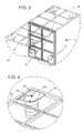
- FIG. 3 illustrates the pivotal connections of the invention's front and rear halves showing opening and closing arch's attendant thereto.
- FIG. 4 illustrates the expandable cushion of the instant invention providing further detail with respect to the pressurized air source line typically used in association with a truck braking system.
- FIG. 5 is a top view of the front and rear halves of the instant invention, further illustrating individual air hoses use in association therewith to inflate expandable bellows.
- FIG. 6 is a bottom view of the mattress support structure of FIG. 5 .
- FIG. 7 is a side view of the mattress support system of FIGS. 5 and 6 showing inflated, expandable cushion means.
- FIG. 8 is an end view of the mattress support system of FIGS. 5 and 6 showing expandable cushion means inflated to essentially equal levels.
- FIG. 9 is an alternative embodiment of the instant invention showing a plurality of additional support members.
- FIG. 10 is a side view of the alternate embodiment illustrated in FIG. 9 .
- FIG. 11 is a bottom of the alternative embodiment illustrated in FIGS. 9 and 10 .
- the adjustable and transportable mattress support arrangement 2 of the instant invention is comprised of identically structured pivotally attached front and rear halves ( 3 , 6 ).
- Each of said halves ( 3 , 6 ) is structured such that a plurality of cross support members 9 intersect and are attached to a longitudinal support member 8 .
- the longitudinal support member 8 traverses the length of each respective half ( 3 , 6 ) and intersects and is attached to a front cross support member 15 and rear support member 17 .
- FIG. 1 Further illustrated in FIG. 1 are inflatable and expandable cushions 7 (shown in a deflated state) and expandable cushion top positioning plates 12 with pressurized gas means 13 inserted through said top positioning plate 12 to provide for independent inflation of each of said expandable cushions 7 . It is to be noted that in practice of the instant invention has been found to be most efficient when said expandable cushions are of an accordion bellows structure and are positioned generally at structured corners located at the intersection of side frame member 10 and front frame member 15 .
- the mattress support member 2 supports the expandable cushions of the instant invention 7 shown in an inflated state wherein the front and rear halves of the mattress support member ( 3 , 6 ) are shown elevated indicated by line 21 .
- the instant invention provides for separate pressurized air sources to be directed to each of said cushions 7 by independent pressurized air hoses 13 . Consequently, the instant invention affords adjustment accommodation at four points of reference (each expandable cushion raised to a distinguishable height).
- FIG. 4 will provide greater detail with respect to said pressurized air hoses 13 and expandable cushions 7 .
- FIG. 3 shows the pivotally attached front and rear halves ( 3 , 6 ) of the adjustable and transportable management support unfolded in phantom and then in a folded or stored state with such folding/storage accommodated via the pivotal arching designated by lines 27 and 28 .
- the pivotal connection of the instant invention is effectuated via hinging means well known and practiced by those skilled in the art.
- FIG. 4 the expandable cushion of the instant invention, shows the pressurized air hose means 13 as shown attached to the top securing plate 12 via a nut or other securing means well known to those in the art.
- the pressurized air hose means extends though the top support plate 12 allowing for the introduction of air or other compatible gas to expand the expandable cushion 7 .
- each of the expandable cushions of the instant invention may be actuated individually to accommodate four points of reference with respect to height adjustment. Said individual height adjustment is facilitated via a valving means (not shown) well known to those skilled in the art wherein one generalized air pressure source enters said valving means and further sub-divides to allow introduction to a plurality of subservient air hoses 13 .
- FIG. 5 illustrates a top view of the front and rear halves of the mattress support arrangement, the invention's front 3 and rear half 6 are shown with their respective cross and longitudinal support members. Further illustrated in FIG. 5 is the top cushioned position plate 12 and the individual air hose means 13 .
- FIG. 6 the bottom view of the mattress support structure of FIG. 5 , the pivotal connection means are shown 25 , as are the bottom support members of the expandable cushions 27 .
- Said bottom support members 27 are means well known by those skilled in the art to accommodate an expandable cushion means.
- FIG. 7 illustrates a side view of the front and rear halves of the instant invention shown with cushions expanded to approximately equal heights.
- FIG. 8 illustrates an end view of one embodiment of the instant invention shown with cushion 7 inflated or expanded to approximate equal heights.
- FIGS. 9–10 illustrate an alternative embodiment of the instant invention.
- FIGS. 9–10 it can be shown where a plurality of inclined support members 33 are further provided to assist in retaining smaller dimension expandable cushions in position once inflated.
- the inclined support members 33 are attached to the bottom of the expandable cushions and rear support members 17 of each pivotally attached support member half.
- FIG. 11 it is further shown in FIG. 11 where in addition to the hinge-like pivotal connections which facilitate connection of front and rear halves of the instant invention each of the inclines support member is attached to the rear support member 17 via a similarly constructed hinging mechanism 35 .
Abstract
An adjustable and transportable mattress support for adjustably supporting a mattress in the cab of a truck including a pivotally connected elongated mattress support member for supporting a mattress; a vertical adjusting system located between the mattress support member and the floor portion of the truck cab, the vertical adjusting system including an expandable gaseous fluid cushion means being expandable and contractable in a vertical direction located between the truck cab floor and the mattress support member; means for applying a gaseous fluid under pressure to expandable cushion means located generally at the corners of the mattress support member between the member and truck cab floor whereby the vertical position of the mattress support member can be adjusted.
Description
This application is not related to any pending applications.
This application is not referenced in any microfiche appendix.
The invention relates to an adjustable mattress support arrangement for adjustably supporting a mattress in the cab of a vehicle such as a truck. More specifically, the invention relates to an arrangement which utilizes expandable air cushions positioned between a rectangularly shaped mattress and a truck cab floor generally at each of the four corners of the rectangularly shaped mattress support member with said member in turn being comprised of pivotally connected first and second sections.
It is an object of the invention to provide a lightweight, adjustable, and easily transportable mattress support apparatus which includes individually expandable air cushion means.
It is a further object of the invention to provide a lightweight adjustable, easily transportable mattress supporting apparatus which provides for independent operation and leveling capability at each corner of a rectangularly shaped mattress support corner.
It is still a further object of the instant invention to provide a lightweight, adjustable and easily transportable mattress support arrangement whereby an essentially level sleeping surface can be provided by independently adjusting on expandable, gaseous fluid cushion means removably positioned between a truck cab floor and a mattress support member.
It is yet another object of the invention is to provide a mattress support member which has pivotally connected front and rear sections wherein said sections may be folded for storage convenience or unfolded to form a sleeping accommodation.
It is a further object of the invention to provide for independent adjustment of expandable, gaseous fluid cushion means via a valving means connected to each of a plurality of expandable cushion means and a vehicle's compressed air supply.
Various attempts to provide adjustable sleeping surfaces as beds have been addressed in the prior art. However, the contemporary art is woefully deficient disclosing a means by which a sleeping surface such as a mattress supported by a mattress support system may be adjusted at multiple points to provide a level or otherwise comfortable sleeping combination. A case in point, would be the situation encountered by most over-the-road (OTR) transport vehicles such as tractor trailer rigs. Most tractor trailer rigs the cab portion (tractor) typically provides for space for sleeping accommodation behind the driver's/passengers' seating area. However, as a level parking surface may not always be available to the tractor/trailer operator, the operator typically finds him or herself facing the situation wherein the truck is on uneven ground or, more specifically, presents an angled orientation which does not lend itself to a comfortable sleeping position.
The instant invention addresses the deficiency in the prior art by disclosing and claiming a mattress support system which allows for at least four points of individual adjustment. This adjustment is facilitated by a valving means which is attached to the tractor trailer compressed air supply and each of a plurality of expandable cushion means such as bellows. The bellows are placed typically in the general area of the corners of the mattress support member and the truck floor to allow the operator to individually adjust each expandable cushion to a desired height thus facilitating a level or otherwise comfortable sleeping surface for the individual operator. Various leveling devices, though deficient, have been disclosed in the prior art.
Phillips (U.S. Pat. No. 2,070,960) relates to fluid hoists or jacks of a small compact, portable fluid jack of relatively great power so as to easily lift an automobile by means of a tire pump or compressed air available in most service stations, and which jack is also adapted for use in combination with the large hydraulic or air hoists in common use in service stations for subsequent lifting of the weight from the springs of an automobile after the automobile has been elevated by the large hydraulic jack.
Nunlist (U.S. Pat. No. 2,769,182) discloses an apparatus for lifting selected portions of a mattress and more particularly to an inflatable mattress lifter.
Bayerkohler (U.S. Pat. No. 2,804,118) relates to improvements in pneumatic jacks for straightening automobile body parts especially although not necessarily. The primary object of the invention is to provide a pneumatic jack of the bellows type adapted for use in straightening automobile bodies and fenders where, because of space limitations, it is impossible to use other types of jacks.
Aymar (U.S. Pat. No. 3,392,412) relates to a bedrest which may be conveniently placed under a mattress for raising and lowering a portion of the mattress, such as the portion constituting the head and backrest of the user, or the portion upon which his feet are located.
Scott (U.S. Pat. No. 3,426,373) discloses an inflatable under-mattress comprises a base member having at each longitudinal side thereof an inflatable chamber. The chambers are independently inflatable. Each chamber is so shaped that when inflated the upper surface thereof is inclined downwardly towards the center of the under-mattress. Each chamber has one longitudinal side extending along the length of the under-mattress along one side thereof. The other side of each chamber is so shaped as to increase the width of the chamber from the foot end to the head end of the under-mattress.
Aymar (U.S. Pat. No. 3,606,623) discloses a bellows assembly for a pneumatically operated adjustable bedrest is provided with integral channel means whereby pressurized air is introduced into what will ultimately be the wider end of the inflated bellows and is then channeled down into the opposed end or apex of the V-shaped bellows. From the apex the pressurized air is then free to move into the separate chambers defined by the channels and the adjacent confronting layers of the bellows. This provides a mechanical advantage which permits smooth elevating action.
Ballard et al. (U.S. Pat. No. 3,667,072) discloses a mattress, as for a hospital bed, an assembly of inflatable bellows spring segments being interposed between the under side of the mattress and a support box therefor which may be said to correspond to the conventional bed spring supporting slats under the springs of conventional mattresses. All of the adjustments offered by conventional hospital bed frames, and more, may be made for the mattress of this invention by virtue of the shapes into which the combinations of spring bellows segments may be inflated. The invention, in effect, employs a careful selection of bellows spring segment shapes, not only to provide a wide range of positional adjustments of the mattress, but these segments may serve, cooperatively, to provide the springs of the mattress, also with the degree of spring or cushioning effect being infinitely adjustable by virtue of the selective inflation of bellows segments, and the selectivity provided as to degree of inflation of the respective bellows.
Swallert (U.S. Pat. No. 3,781,928) discloses a device for raising an lowering the head end and/or foot end of a mattress of a bed from a bedstead comprising an inflatable pad positioned at the head end and/or foot end of the bedstead between the bedstead and the mattress to raise or lower the associated end of the mattress. The pad is mounted in a frame which is composed of upper and lower hinged U-shaped parts each of which includes a plate of thin rigid material flexedly attached to the parallel legs of the associated frame part. The pad is attached only to the plate of the bottom part and is free to slide on the plate of the upper part when the mattress is raised and lowered in the course of inflation and deflation of the pad.
Pierson (U.S. Pat. No. 4,142,263) discloses an improvement in mechanisms for elevating a mattress on a bed by a simple inflatable pillow inserted under the mattress and of novel prismatic geometrical construction enabling highly flexible adaptability of use and simplicity of operation.
Ryder et al. (U.S. Pat. No. 4,807,313) discloses a system for selectively supporting a mattress at a predetermined angle of inclination with respect to a support surface, such as a box spring, or the like. The system comprises primarily an inflatable mattress support member which is connected to a selectively operable pneumatic pump via a combination check valve and release valve. In practice, the user or patient can inflate the mattress support member to provide the desired degree of inclination and when not in use the support member can be easily deflated to dispose the mattress in a relatively normal position. The mattress support member is provided by a plurality of adjacent interconnected inflatable cells, with the adjacent cells sharing a common wall portion having port means formed therein to pneumatically interconnect the respective cells. The cells are of declining size, starting at a first end of the inflatable mattress support member and progressing toward the opposite, second end thereof, and preferably ten or more cells are provided. The construction of the mattress support member is provided by a pair of sheet members which are bonded together about the periphery thereof, and are further bonded together at selected areas intermediate the ends thereof, which selected areas of bonding are spaced apart by varying distances and extend generally across the width of the mattress support member, except for those locations wherein the bonding is interrupted to provide openings or ports between the respective cells.
Yamaguchi (U.S. Pat. No. 5,313,679) discloses a bed having a base, a mattress, and a system for moving the mattress up and down for helping a person make the bed, and can be preferably adapted in a guest room of hotels or the like. The present invention provides a bed comprising a base, a mattress provided on a top face of the base, a pair of inflatable means provided between the mattress and the base, and an air-supplying tube connected with said inflatable means, wherein one of the inflatable means is laid on one side of the top surface of the base, while the other is laid on the other side of the top surface of the base, and each inflatable means is independently connected to an air-supplying means through the air-supplying tube.
In view of the limitations and disadvantages of the afore-cited prior art, it is apparent that what is needed is a method and apparatus for leveling a transportable bed assembly at least four points of adjustment a need and exceeded by the instant invention. Consequently, it is an object of the instant invention to provide a lightweight, adjustable and easy transportable mattress support apparatus which includes individually expandable air cushion means.
The invention will be better understood by an examination of the following description, together with the accompanying drawings, in which:
While the making and using of various embodiments of the present invention are discussed in detail below, it should be appreciated that the present invention provides for inventive concepts capable of being embodied in a variety of specific contexts. The specific embodiments discussed herein are merely illustrative of specific manners in which to make and use the invention and are not to be interpreted as limiting the scope of the instant invention.
The claims and the specification describe the invention presented and the terms that are employed in the claims draw their meaning from the use of such terms in the specification. The same terms employed in the prior art may be broader in meaning than specifically employed herein. Whenever there is a question between the broader definition of such terms used in the prior art and the more specific use of the terms herein, the more specific meaning is meant.
While the invention has been described with a certain degree of particularity, it is clear that many changes may be made in the details of construction and the arrangement of components without departing from the spirit and scope of this disclosure. It is understood that the invention is not limited to the embodiments set forth herein for purposes of exemplification, but is to be limited only by the scope of the attached claim or claims, including the full range of equivalency to which each element thereof is entitled.
As seen in the embodiment illustrated in FIGS. 1–8 , the adjustable and transportable mattress support arrangement 2 of the instant invention is comprised of identically structured pivotally attached front and rear halves (3,6). Each of said halves (3,6) is structured such that a plurality of cross support members 9 intersect and are attached to a longitudinal support member 8. The longitudinal support member 8 traverses the length of each respective half (3,6) and intersects and is attached to a front cross support member 15 and rear support member 17.
Further illustrated in FIG. 1 are inflatable and expandable cushions 7 (shown in a deflated state) and expandable cushion top positioning plates 12 with pressurized gas means 13 inserted through said top positioning plate 12 to provide for independent inflation of each of said expandable cushions 7. It is to be noted that in practice of the instant invention has been found to be most efficient when said expandable cushions are of an accordion bellows structure and are positioned generally at structured corners located at the intersection of side frame member 10 and front frame member 15.
In FIG. 2 , the mattress support member 2, supports the expandable cushions of the instant invention 7 shown in an inflated state wherein the front and rear halves of the mattress support member (3,6) are shown elevated indicated by line 21. It is important to note that the instant invention provides for separate pressurized air sources to be directed to each of said cushions 7 by independent pressurized air hoses 13. Consequently, the instant invention affords adjustment accommodation at four points of reference (each expandable cushion raised to a distinguishable height).
As illustrated in FIG. 2 , FIG. 4 will provide greater detail with respect to said pressurized air hoses 13 and expandable cushions 7.
As indicated in association with FIG. 2 , each of the expandable cushions of the instant invention may be actuated individually to accommodate four points of reference with respect to height adjustment. Said individual height adjustment is facilitated via a valving means (not shown) well known to those skilled in the art wherein one generalized air pressure source enters said valving means and further sub-divides to allow introduction to a plurality of subservient air hoses 13.
While this invention has been described to illustrative embodiments, this description is not to be construed in a limiting sense. Various modifications and combinations of the illustrative embodiments as well as other embodiments will be apparent to those skilled in the art upon referencing this disclosure. It is therefore intended that this disclosure encompass any such modifications or embodiments.
The foregoing description, for purposes of explanation, used specific nomenclature to provide a thorough understanding of the invention. However, it will be apparent to one skilled in the art that the specific details are not required in order to practice the invention. In other instances, well known circuits and devices are shown in block diagram form in order to avoid unnecessary distraction from the underlying invention. Thus, the foregoing descriptions of specific embodiments of the present invention are presented for purposes of illustration and description. They are not intended to be exhaustive or to limit the invention to the precise forms disclosed, obviously many modifications and variations are possible in view of the above teachings. The embodiments were chosen and described in order to best explain the principles of the invention and its practical applications, to thereby enable others skilled in the art to best utilize the invention and various embodiments with various modifications as are suited to the particular use contemplated. It is intended that the scope of the invention be defined by the following claims and their equivalents
Claims (5)
1. An adjustable and transportable mattress support arrangement for adjustably supporting a
mattress in the cab of a truck, comprising:
two elongated mattress support members for supporting said mattress each of said members having a distal end and a proximal end and being pivotally attached to each other at their proximal ends such that their distal ends comprise four corners of the arrangement;
four expandable gaseous fluid cushion means each being expandable and contractible in a vertical direction and removably positioned between a truck cab floor and a respective mattress support member, each of the cushion means being attached to one of the four corners of the arrangement;
means for applying a gaseous fluid under pressure to said expandable cushion means such that the gaseous fluid pressure is regulated such that each of the cushion means may have a different amount of pressure applied to it and whereby the vertical position of each mattress support member can be adjusted and whereby said mattress support members are supported by said expandable cushion means.
2. A support arrangement as defined in claim 1 , wherein said mattress support arrangement may be folded for storage convenience.
3. The support arrangement of claim 1 wherein said elongated mattress support arrangement may be folded and attached in a non-permanent manner to the rearmost vertical wall of said truck cab.
4. A support arrangement as defined in claim 1 wherein said means for applying a gaseous fluid under pressure comprises:
a valving means connected to each of said expandable gaseous fluid cushion means and a pressurized air source used in association with a truck braking system.
5. A support arrangement as defined in claim 1 wherein said expandable gaseous fluid cushion means is an expandable air cushion.
Priority Applications (1)
| Application Number | Priority Date | Filing Date | Title |
|---|---|---|---|
| US10/630,491 US6993798B1 (en) | 2003-07-30 | 2003-07-30 | Method and apparatus for leveling a transportable bed assembly |
Applications Claiming Priority (1)
| Application Number | Priority Date | Filing Date | Title |
|---|---|---|---|
| US10/630,491 US6993798B1 (en) | 2003-07-30 | 2003-07-30 | Method and apparatus for leveling a transportable bed assembly |
Publications (1)
| Publication Number | Publication Date |
|---|---|
| US6993798B1 true US6993798B1 (en) | 2006-02-07 |
Family
ID=35734067
Family Applications (1)
| Application Number | Title | Priority Date | Filing Date |
|---|---|---|---|
| US10/630,491 Expired - Fee Related US6993798B1 (en) | 2003-07-30 | 2003-07-30 | Method and apparatus for leveling a transportable bed assembly |
Country Status (1)
| Country | Link |
|---|---|
| US (1) | US6993798B1 (en) |
Cited By (11)
| Publication number | Priority date | Publication date | Assignee | Title |
|---|---|---|---|---|
| US7146662B1 (en) * | 2005-09-14 | 2006-12-12 | Michael H Pollard | Self-leveling bed support frame |
| US20080022458A1 (en) * | 2004-05-27 | 2008-01-31 | Jeff Snelling | Mattress leveling device |
| US7416378B1 (en) * | 2006-09-12 | 2008-08-26 | Adams Bill J | Load lift control system |
| US20090025149A1 (en) * | 2007-07-29 | 2009-01-29 | Chan Jui-Peng | Adjusting Structure for Adjusting the Rise and Fall of a Mattress by Air Spring |
| WO2010132961A3 (en) * | 2009-05-06 | 2011-01-13 | Hermans, Pascal | Supporting structure |
| US8468626B2 (en) | 2011-10-21 | 2013-06-25 | Ralph Carrier | Cab sleeper |
| US20190059601A1 (en) * | 2017-08-30 | 2019-02-28 | Dreamwell, Ltd. | Adjustable support legs for a mattress foundation |
| US10259348B2 (en) | 2017-06-30 | 2019-04-16 | Toyota Motor Engineering & Manufacturing North America, Inc. | Sway control for suspended furniture in a vehicle |
| US10426277B2 (en) * | 2016-04-12 | 2019-10-01 | Joseph Frank Cerri, III | Inflatable under the bed filler |
| CN112545244A (en) * | 2020-12-01 | 2021-03-26 | 上海金字塔睡眠科技有限公司 | Physiotherapy and sleep-aid power device |
| JP2023027734A (en) * | 2021-08-17 | 2023-03-02 | エア ボックス シーオー.エルティーディー. | Multipurpose tent also serving as bed |
Citations (38)
| Publication number | Priority date | Publication date | Assignee | Title |
|---|---|---|---|---|
| US1303487A (en) * | 1919-05-13 | Portable eoldibta bed | ||
| US1554310A (en) * | 1924-03-25 | 1925-09-22 | John V Trepele | Foldable bed structure |
| US2070960A (en) | 1936-01-11 | 1937-02-16 | Rodney F Phillips | Jack |
| US2495092A (en) | 1945-12-28 | 1950-01-17 | Firestone Tire & Rubber Co | Pneumatic jack inflatable by exhaust of automobiles |
| US2602938A (en) * | 1948-02-04 | 1952-07-15 | Jefferson R Williams | Folding automobile bed |
| US2609177A (en) | 1948-12-15 | 1952-09-02 | George E Hughes | Automobile jack |
| US2616098A (en) * | 1949-12-23 | 1952-11-04 | Leland B Love | Folding cot structure |
| US2769182A (en) | 1954-04-21 | 1956-11-06 | Erwin J Nunlist | Inflatable mattress lifters |
| US2804118A (en) | 1954-09-13 | 1957-08-27 | Irvin L Bayerkohler | Pneumatic bellows type jacks |
| US2918682A (en) | 1958-09-19 | 1959-12-29 | Carl B Thoresen | Foot and back rest |
| US3299447A (en) * | 1965-02-09 | 1967-01-24 | Artnell Company | Suspension system for mattresses and the like |
| US3371359A (en) | 1966-09-22 | 1968-03-05 | Artnell Company | Mattress suspension system |
| US3392412A (en) | 1967-01-12 | 1968-07-16 | Aymar Julian Robert | Adjustable bedrest |
| US3426373A (en) | 1965-10-18 | 1969-02-11 | James H S Scott | Inflatable mattresses |
| US3606623A (en) | 1970-01-09 | 1971-09-21 | Surgical Dynamics Inc | Adjustable bedrest with improved bellows structure |
| US3667075A (en) | 1970-02-24 | 1972-06-06 | Wesley D Ballard | Mattress spring bellows assembly as for hospitals, and the like |
| US3760436A (en) | 1971-11-05 | 1973-09-25 | Universal Oil Prod Co | Suspension system for vehicle mounted bed |
| US3781928A (en) | 1971-04-05 | 1974-01-01 | Erik Pettersson | Device for raising the head end and/or foot end of a bed |
| US4142263A (en) | 1977-11-25 | 1979-03-06 | Maine Ideas Incorporated | Bed-mattress elevating system and the like |
| US4144601A (en) | 1978-02-10 | 1979-03-20 | Anderson Alan J | Air ride sleeper for trucks |
| US4196483A (en) | 1978-07-19 | 1980-04-08 | Kahl George H Jr | Portable mattress support |
| US4309783A (en) | 1980-02-06 | 1982-01-12 | Teledyne Industries, Inc. | Adjustably conformable bed |
| US4527298A (en) | 1982-03-18 | 1985-07-09 | Moulton Lee A | Electro pneumatic bed |
| US4572579A (en) | 1983-12-19 | 1986-02-25 | Ken Saito | Dump apparatus |
| US4669139A (en) | 1985-08-30 | 1987-06-02 | Navistar International Corporation | Reclining bunk for sleeper |
| US4807313A (en) | 1985-12-03 | 1989-02-28 | Ryder International Corporation | Inflatable inclined mattress support system |
| US4979248A (en) * | 1989-07-14 | 1990-12-25 | John May | Air suspension bed for vehicles |
| US4989281A (en) | 1990-05-16 | 1991-02-05 | Christensen Daniel L | Adjustable bed for a truck-trailer system |
| US5218728A (en) | 1992-11-10 | 1993-06-15 | Mac Ride, Inc. | Vibration isolation apparatus for vehicle sleeper beds |
| US5313679A (en) | 1992-02-28 | 1994-05-24 | Yoshihisa Yamaguchi | Bed having system for moving mattress up and down |
| US5446938A (en) | 1993-10-04 | 1995-09-05 | Kelley Company Inc. | Bag construction for a dockleveler |
| US5598591A (en) | 1995-01-13 | 1997-02-04 | Kelley; Roland F. | Adjustable mattress support arrangement for vehicles such as trucks |
| US5638560A (en) | 1995-12-26 | 1997-06-17 | Rigdon; Charles V. | Sleeper bed for over-the-road tractors |
| US6311348B1 (en) | 1998-04-22 | 2001-11-06 | Hill-Rom Services, Inc. | Bed assembly with an air mattress and controller |
| US6505363B2 (en) * | 2000-12-26 | 2003-01-14 | Rocky E. Davis | Device for adjusting the plane of a mattress |
| US6631526B1 (en) * | 1996-12-13 | 2003-10-14 | Russell V. Enright | Vehicle sleeper system with improved suspension control |
| US6671900B2 (en) * | 2000-03-08 | 2004-01-06 | Waldon Davis | Bed leveler/adjuster |
| US6718574B1 (en) * | 2003-04-02 | 2004-04-13 | International Truck Intellectual Property Company, Llc | Bunk leveling support assembly |
-
2003
- 2003-07-30 US US10/630,491 patent/US6993798B1/en not_active Expired - Fee Related
Patent Citations (38)
| Publication number | Priority date | Publication date | Assignee | Title |
|---|---|---|---|---|
| US1303487A (en) * | 1919-05-13 | Portable eoldibta bed | ||
| US1554310A (en) * | 1924-03-25 | 1925-09-22 | John V Trepele | Foldable bed structure |
| US2070960A (en) | 1936-01-11 | 1937-02-16 | Rodney F Phillips | Jack |
| US2495092A (en) | 1945-12-28 | 1950-01-17 | Firestone Tire & Rubber Co | Pneumatic jack inflatable by exhaust of automobiles |
| US2602938A (en) * | 1948-02-04 | 1952-07-15 | Jefferson R Williams | Folding automobile bed |
| US2609177A (en) | 1948-12-15 | 1952-09-02 | George E Hughes | Automobile jack |
| US2616098A (en) * | 1949-12-23 | 1952-11-04 | Leland B Love | Folding cot structure |
| US2769182A (en) | 1954-04-21 | 1956-11-06 | Erwin J Nunlist | Inflatable mattress lifters |
| US2804118A (en) | 1954-09-13 | 1957-08-27 | Irvin L Bayerkohler | Pneumatic bellows type jacks |
| US2918682A (en) | 1958-09-19 | 1959-12-29 | Carl B Thoresen | Foot and back rest |
| US3299447A (en) * | 1965-02-09 | 1967-01-24 | Artnell Company | Suspension system for mattresses and the like |
| US3426373A (en) | 1965-10-18 | 1969-02-11 | James H S Scott | Inflatable mattresses |
| US3371359A (en) | 1966-09-22 | 1968-03-05 | Artnell Company | Mattress suspension system |
| US3392412A (en) | 1967-01-12 | 1968-07-16 | Aymar Julian Robert | Adjustable bedrest |
| US3606623A (en) | 1970-01-09 | 1971-09-21 | Surgical Dynamics Inc | Adjustable bedrest with improved bellows structure |
| US3667075A (en) | 1970-02-24 | 1972-06-06 | Wesley D Ballard | Mattress spring bellows assembly as for hospitals, and the like |
| US3781928A (en) | 1971-04-05 | 1974-01-01 | Erik Pettersson | Device for raising the head end and/or foot end of a bed |
| US3760436A (en) | 1971-11-05 | 1973-09-25 | Universal Oil Prod Co | Suspension system for vehicle mounted bed |
| US4142263A (en) | 1977-11-25 | 1979-03-06 | Maine Ideas Incorporated | Bed-mattress elevating system and the like |
| US4144601A (en) | 1978-02-10 | 1979-03-20 | Anderson Alan J | Air ride sleeper for trucks |
| US4196483A (en) | 1978-07-19 | 1980-04-08 | Kahl George H Jr | Portable mattress support |
| US4309783A (en) | 1980-02-06 | 1982-01-12 | Teledyne Industries, Inc. | Adjustably conformable bed |
| US4527298A (en) | 1982-03-18 | 1985-07-09 | Moulton Lee A | Electro pneumatic bed |
| US4572579A (en) | 1983-12-19 | 1986-02-25 | Ken Saito | Dump apparatus |
| US4669139A (en) | 1985-08-30 | 1987-06-02 | Navistar International Corporation | Reclining bunk for sleeper |
| US4807313A (en) | 1985-12-03 | 1989-02-28 | Ryder International Corporation | Inflatable inclined mattress support system |
| US4979248A (en) * | 1989-07-14 | 1990-12-25 | John May | Air suspension bed for vehicles |
| US4989281A (en) | 1990-05-16 | 1991-02-05 | Christensen Daniel L | Adjustable bed for a truck-trailer system |
| US5313679A (en) | 1992-02-28 | 1994-05-24 | Yoshihisa Yamaguchi | Bed having system for moving mattress up and down |
| US5218728A (en) | 1992-11-10 | 1993-06-15 | Mac Ride, Inc. | Vibration isolation apparatus for vehicle sleeper beds |
| US5446938A (en) | 1993-10-04 | 1995-09-05 | Kelley Company Inc. | Bag construction for a dockleveler |
| US5598591A (en) | 1995-01-13 | 1997-02-04 | Kelley; Roland F. | Adjustable mattress support arrangement for vehicles such as trucks |
| US5638560A (en) | 1995-12-26 | 1997-06-17 | Rigdon; Charles V. | Sleeper bed for over-the-road tractors |
| US6631526B1 (en) * | 1996-12-13 | 2003-10-14 | Russell V. Enright | Vehicle sleeper system with improved suspension control |
| US6311348B1 (en) | 1998-04-22 | 2001-11-06 | Hill-Rom Services, Inc. | Bed assembly with an air mattress and controller |
| US6671900B2 (en) * | 2000-03-08 | 2004-01-06 | Waldon Davis | Bed leveler/adjuster |
| US6505363B2 (en) * | 2000-12-26 | 2003-01-14 | Rocky E. Davis | Device for adjusting the plane of a mattress |
| US6718574B1 (en) * | 2003-04-02 | 2004-04-13 | International Truck Intellectual Property Company, Llc | Bunk leveling support assembly |
Cited By (14)
| Publication number | Priority date | Publication date | Assignee | Title |
|---|---|---|---|---|
| US20080022458A1 (en) * | 2004-05-27 | 2008-01-31 | Jeff Snelling | Mattress leveling device |
| US7146662B1 (en) * | 2005-09-14 | 2006-12-12 | Michael H Pollard | Self-leveling bed support frame |
| US7416378B1 (en) * | 2006-09-12 | 2008-08-26 | Adams Bill J | Load lift control system |
| US20090025149A1 (en) * | 2007-07-29 | 2009-01-29 | Chan Jui-Peng | Adjusting Structure for Adjusting the Rise and Fall of a Mattress by Air Spring |
| US7562409B2 (en) * | 2007-07-29 | 2009-07-21 | Chan Jui-Peng | Adjusting structure for adjusting the rise and fall of a mattress by air spring |
| BE1018547A3 (en) * | 2009-05-06 | 2011-03-01 | Hermans Pascal | BEARING STRUCTURE. |
| WO2010132961A3 (en) * | 2009-05-06 | 2011-01-13 | Hermans, Pascal | Supporting structure |
| US8468626B2 (en) | 2011-10-21 | 2013-06-25 | Ralph Carrier | Cab sleeper |
| US10426277B2 (en) * | 2016-04-12 | 2019-10-01 | Joseph Frank Cerri, III | Inflatable under the bed filler |
| US10259348B2 (en) | 2017-06-30 | 2019-04-16 | Toyota Motor Engineering & Manufacturing North America, Inc. | Sway control for suspended furniture in a vehicle |
| US20190059601A1 (en) * | 2017-08-30 | 2019-02-28 | Dreamwell, Ltd. | Adjustable support legs for a mattress foundation |
| US10973336B2 (en) * | 2017-08-30 | 2021-04-13 | Dreamwell, Ltd. | Adjustable support legs for a mattress foundation |
| CN112545244A (en) * | 2020-12-01 | 2021-03-26 | 上海金字塔睡眠科技有限公司 | Physiotherapy and sleep-aid power device |
| JP2023027734A (en) * | 2021-08-17 | 2023-03-02 | エア ボックス シーオー.エルティーディー. | Multipurpose tent also serving as bed |
Similar Documents
| Publication | Publication Date | Title |
|---|---|---|
| US6886204B2 (en) | Multiple position air mattress system | |
| CA2060996C (en) | Air adjustable bed | |
| US6739005B2 (en) | Bed with adjustable elevation components | |
| US7231681B2 (en) | Multiple position air mattress system | |
| US7409735B2 (en) | Dynamic cellular person support surface | |
| US6993798B1 (en) | Method and apparatus for leveling a transportable bed assembly | |
| US3978530A (en) | Air inflatable bed-like device with adjustable back support | |
| US5815862A (en) | Portable orthopedic bed | |
| EP2877058B1 (en) | Adjustable width mattress | |
| US20060016016A1 (en) | Modular bed system | |
| US20060101580A1 (en) | Adjustable Width Bariatric Transport Support Surface | |
| US9277827B2 (en) | Mattress deflation management | |
| WO2008131055A1 (en) | Inflatable two chamber bed with raised headboard | |
| US20120137440A1 (en) | Vacuum control of seat section bladders | |
| US6163908A (en) | Air sac for oscillating low air loss bed | |
| AU2015292291B2 (en) | Therapeutic mattress with low volume bladders | |
| WO1988009650A1 (en) | Air sac for oscillating low air loss bed | |
| US6772462B1 (en) | Tiltable bed | |
| US11470978B2 (en) | Oblique hinged panels and bladder apparatus for sleep disorders | |
| US20080022458A1 (en) | Mattress leveling device | |
| CN111839946A (en) | Pressure injury prevention pad and device | |
| US20050262630A1 (en) | Mattress leveling system | |
| JPH06335501A (en) | Air mat device | |
| AU624075B2 (en) | Air sac for oscillating low air loss bed | |
| JPH04269914A (en) | Reclining bed |
Legal Events
| Date | Code | Title | Description |
|---|---|---|---|
| FPAY | Fee payment |
Year of fee payment: 4 |
|
| REMI | Maintenance fee reminder mailed | ||
| LAPS | Lapse for failure to pay maintenance fees | ||
| STCH | Information on status: patent discontinuation |
Free format text: PATENT EXPIRED DUE TO NONPAYMENT OF MAINTENANCE FEES UNDER 37 CFR 1.362 |
|
| FP | Expired due to failure to pay maintenance fee |
Effective date: 20140207 |