US6995922B2 - Zoom lens and electronic imaging apparatus having the same - Google Patents
Zoom lens and electronic imaging apparatus having the same Download PDFInfo
- Publication number
- US6995922B2 US6995922B2 US10/750,798 US75079804A US6995922B2 US 6995922 B2 US6995922 B2 US 6995922B2 US 75079804 A US75079804 A US 75079804A US 6995922 B2 US6995922 B2 US 6995922B2
- Authority
- US
- United States
- Prior art keywords
- lens unit
- lens
- zoom
- zoom lens
- wide
- Prior art date
- Legal status (The legal status is an assumption and is not a legal conclusion. Google has not performed a legal analysis and makes no representation as to the accuracy of the status listed.)
- Expired - Lifetime, expires
Links
- 238000003384 imaging method Methods 0.000 title claims abstract description 164
- 230000003287 optical effect Effects 0.000 claims abstract description 596
- 238000005452 bending Methods 0.000 claims description 61
- 230000001771 impaired effect Effects 0.000 claims description 24
- 238000012545 processing Methods 0.000 claims description 22
- 230000004075 alteration Effects 0.000 description 115
- 238000010586 diagram Methods 0.000 description 60
- 238000012937 correction Methods 0.000 description 42
- 230000002349 favourable effect Effects 0.000 description 34
- 239000006059 cover glass Substances 0.000 description 30
- 230000005499 meniscus Effects 0.000 description 30
- 238000013461 design Methods 0.000 description 24
- 238000002834 transmittance Methods 0.000 description 23
- 239000011248 coating agent Substances 0.000 description 22
- 238000000576 coating method Methods 0.000 description 22
- 210000001747 pupil Anatomy 0.000 description 17
- 239000013078 crystal Substances 0.000 description 16
- 206010010071 Coma Diseases 0.000 description 15
- 230000008859 change Effects 0.000 description 15
- 230000003247 decreasing effect Effects 0.000 description 10
- 230000000694 effects Effects 0.000 description 10
- 238000004519 manufacturing process Methods 0.000 description 10
- 238000000034 method Methods 0.000 description 9
- 230000035945 sensitivity Effects 0.000 description 9
- 239000004973 liquid crystal related substance Substances 0.000 description 8
- 238000004891 communication Methods 0.000 description 7
- 201000009310 astigmatism Diseases 0.000 description 6
- 230000008901 benefit Effects 0.000 description 5
- 230000007246 mechanism Effects 0.000 description 5
- 229910052709 silver Inorganic materials 0.000 description 5
- 239000004332 silver Substances 0.000 description 5
- -1 silver halide Chemical class 0.000 description 5
- 238000013459 approach Methods 0.000 description 4
- 230000000295 complement effect Effects 0.000 description 3
- 230000006866 deterioration Effects 0.000 description 3
- 239000011521 glass Substances 0.000 description 3
- 230000003595 spectral effect Effects 0.000 description 3
- 238000004364 calculation method Methods 0.000 description 2
- 230000007547 defect Effects 0.000 description 2
- 230000010365 information processing Effects 0.000 description 2
- 239000000463 material Substances 0.000 description 2
- 230000009467 reduction Effects 0.000 description 2
- 239000011347 resin Substances 0.000 description 2
- 229920005989 resin Polymers 0.000 description 2
- 239000000126 substance Substances 0.000 description 2
- 241000196324 Embryophyta Species 0.000 description 1
- 235000005811 Viola adunca Nutrition 0.000 description 1
- 240000009038 Viola odorata Species 0.000 description 1
- 235000013487 Viola odorata Nutrition 0.000 description 1
- 235000002254 Viola papilionacea Nutrition 0.000 description 1
- 239000003086 colorant Substances 0.000 description 1
- 239000000470 constituent Substances 0.000 description 1
- 239000000428 dust Substances 0.000 description 1
- 238000005286 illumination Methods 0.000 description 1
- 230000006872 improvement Effects 0.000 description 1
- GQYHUHYESMUTHG-UHFFFAOYSA-N lithium niobate Chemical compound [Li+].[O-][Nb](=O)=O GQYHUHYESMUTHG-UHFFFAOYSA-N 0.000 description 1
- 238000005259 measurement Methods 0.000 description 1
- 230000008569 process Effects 0.000 description 1
- 239000010453 quartz Substances 0.000 description 1
- 238000009877 rendering Methods 0.000 description 1
- 230000000630 rising effect Effects 0.000 description 1
- 230000009291 secondary effect Effects 0.000 description 1
- 238000000926 separation method Methods 0.000 description 1
- VYPSYNLAJGMNEJ-UHFFFAOYSA-N silicon dioxide Inorganic materials O=[Si]=O VYPSYNLAJGMNEJ-UHFFFAOYSA-N 0.000 description 1
- 238000004088 simulation Methods 0.000 description 1
- XLYOFNOQVPJJNP-UHFFFAOYSA-N water Substances O XLYOFNOQVPJJNP-UHFFFAOYSA-N 0.000 description 1
Images


Classifications
-
- G—PHYSICS
- G02—OPTICS
- G02B—OPTICAL ELEMENTS, SYSTEMS OR APPARATUS
- G02B15/00—Optical objectives with means for varying the magnification
- G02B15/14—Optical objectives with means for varying the magnification by axial movement of one or more lenses or groups of lenses relative to the image plane for continuously varying the equivalent focal length of the objective
- G02B15/144—Optical objectives with means for varying the magnification by axial movement of one or more lenses or groups of lenses relative to the image plane for continuously varying the equivalent focal length of the objective having four groups only
- G02B15/1445—Optical objectives with means for varying the magnification by axial movement of one or more lenses or groups of lenses relative to the image plane for continuously varying the equivalent focal length of the objective having four groups only the first group being negative
- G02B15/144515—Optical objectives with means for varying the magnification by axial movement of one or more lenses or groups of lenses relative to the image plane for continuously varying the equivalent focal length of the objective having four groups only the first group being negative arranged -+++
-
- G—PHYSICS
- G02—OPTICS
- G02B—OPTICAL ELEMENTS, SYSTEMS OR APPARATUS
- G02B5/00—Optical elements other than lenses
- G02B5/04—Prisms
Definitions
- This invention relates to a zoom lens suitable for an electronic imaging apparatus, such as a video camera or a digital camera, in which a slim design relating to a depth and a wide-angle design of the zoom lens have been realized, and to the electronic imaging apparatus having the zoom lens.
- a thickness extending from the most object-side surface of an optical system to an imaging plane constitutes the greatest obstacle to a reduction in depth of a camera. In particularly, in a zoom optical system, this thickness offers an obstacle.
- the collapsible lens barrel is constructed so that the optical system protrudes from the front side of the camera body in photography, but it is incorporated in the camera body when the camera is carried.
- Optical systems in which the collapsible lens barrel is used and the slim design is effectively achieved are set forth, for example, in Japanese Patent Kokai Nos. Hei 11-194274, Hei 11-287953, and 2000-9997.
- Each of the optical systems described in these publications includes, in order from the object side, a first lens unit with negative refracting power and a second lens unit with positive refracting power so that when the magnification of the optical system is changed, both the first lens unit and the second lens unit are moved.
- the optical system of the electronic imaging apparatus of this type is constructed so that the optical path (optical axis) of the optical system is bent by a reflecting optical element such as a mirror or a prism. Specifically, the most object-side lens unit of the optical system is fixed and the reflecting optical element is provided therein. The optical path running behind this lens is bent in a longitudinal or lateral direction of the camera body. By doing so, the smallest possible dimension of the depth is obtained.
- a diverging surface is necessarily provided on the object side of the reflecting surface of the reflecting optical element.
- a negative meniscus lens with a concave surface facing the image side of the reflecting optical element is placed.
- the zoom lens according to the present invention comprises a lens unit located at the most object-side position and a moving lens unit with positive refracting power, located on the image side of the lens unit.
- the lens unit includes a single positive lens and the moving lens unit is simply moved toward the object side when the magnification of the zoom lens is changed in the range from a wide-angle position to a telephoto position so as to satisfy the following condition: 0.8 ⁇ y 07 /( fw ⁇ tan ⁇ 07w ) ⁇ 0.96 where fw is the focal length of the entire system of the zoom lens at the wide-angle position, y 07 is an image height expressed by 0.7 ⁇ y 10 , where y 10 is a distance from the center to a point farthest therefrom on the effective imaging surface of an electronic image sensor, and ⁇ 07w is an angle made by a direction of an object point with an optical axis, where the object point corresponds to an image point that is at the point y 07 away from the center on the effective imaging surface of the electronic image
- the lens unit includes at least one cemented lens component of a positive lens and a negative lens, arranged in this order from the object side.
- the lens unit includes at least one optical element with negative refracting power and the optical element has at least one aspherical surface.
- the lens unit has an optical element with negative refracting power at the most object-side position and satisfies the following condition: ⁇ 1.5 ⁇ ( R 11 + R 12 )/( R 11 ⁇ R 12 ) ⁇ 1.1 where R 11 is the radius of curvature of the entrance surface of the optical element and R 12 is the radius of curvature of the exit surface of the optical element.
- the lens unit and the aperture stop are fixed when the magnification is changed.
- the lens unit has a reflecting optical element.
- the most object-side surface of the reflecting optical element is concave.
- the lens unit includes a positive lens, having positive refracting power as a whole.
- the entrance surface of the reflecting optical element is configured as an aspherical surface that divergence is impaired progressively in going from the optical axis to the periphery.
- the zoom lens according to the present invention preferably satisfies the following condition: 0.3 ⁇ d F /d p ⁇ 0.7 where d F is a distance from an intersection of the most object-side surface of the lens unit with the optical axis to an intersection of the reflecting surface with the optical axis and d p is a distance, measured along the optical axis, from an intersection of the most object-side refracting surface relative to the reflecting surface with the optical axis to an intersection of the most image-side refracting surface relative to the reflecting surface with the optical axis.
- the zoom lens according to the present invention preferably has a lens unit with negative refracting power located adjacent to the lens unit, on the image side of the lens unit, and the lens unit with negative refracting power includes a negative lens and a positive lens.
- the zoom lens according to the present invention preferably has a lens unit with negative refracting power located adjacent to the lens unit, on the image side of the lens unit, and the aperture stop is interposed between the lens unit with negative refracting power and the moving lens unit.
- the zoom lens according to the present invention comprises a first lens unit with positive refracting power, located at the most object-side position; a second lens unit with negative refracting power, located on the image side of the first lens unit; and a third lens unit with positive refracting power, located on the image side of the second lens unit.
- the zoom lens is constructed so that the first lens unit has two aspherical surfaces, and when the magnification of the zoom lens is changed in the range from the wide-angle position to the telephoto position, the second lens unit is moved and the third lens unit is simply moved toward the object side.
- the zoom lens according to the present invention comprises a first lens unit with positive refracting power, located at the most object-side position; a second lens unit with negative refracting power, located on the image side of the first lens unit; and a third lens unit with positive refracting power, located on the image side of the second lens unit.
- the zoom lens is constructed so that the first lens unit and the second lens unit have four aspherical surfaces, and when the magnification of the zoom lens is changed in the range from the wide-angle position to the telephoto position, the second lens unit is moved and the third lens unit is simply moved toward the object side.
- the zoom lens according to the present invention comprises a first lens unit with positive refracting power, located at the most object-side position; a second lens unit with negative refracting power, located on the image side of the first lens unit; and a third lens unit with positive refracting power, located on the image side of the second lens unit.
- the zoom lens is constructed so that each of the first lens unit and the second lens unit has two aspherical surfaces in total, and when the magnification of the zoom lens is changed in the range from the wide-angle position to the telephoto position, the second lens unit is moved and the third lens unit is simply moved toward the object side.
- the zoom lens according to the present invention comprises a first lens unit with positive refracting power, located at the most object-side position; a second lens unit with negative refracting power, located on the image side of the first lens unit; and a third lens unit with positive refracting power, located on the image side of the second lens unit.
- the zoom lens is constructed so that the second lens unit and the third lens unit have four aspherical surfaces in total, and when the magnification of the zoom lens is changed in the range from the wide-angle position to the telephoto position, the second lens unit is moved and the third lens unit is simply moved toward the object side.
- the zoom lens according to the present invention comprises a first lens unit with positive refracting power, located at the most object-side position; a second lens unit with negative refracting power, located on the image side of the first lens unit; and a third lens unit with positive refracting power, located on the image side of the second lens unit.
- the zoom lens is constructed so that each of the second lens unit and the third lens unit has two aspherical surfaces, and when the magnification of the zoom lens is changed in the range from the wide-angle position to the telephoto position, the second lens unit is moved and the third lens unit is simply moved toward the object side.
- the first lens unit includes an optical element of divergence and a positive lens, arranged in this order from the object side along the optical path.
- the second lens unit includes a biconcave lens and a positive lens, arranged in this order from the object side along the optical path.
- the third lens unit includes a single positive lens and a cemented lens component of a positive lens and a negative lens with a concave surface of strong power facing the image side, arrange in this order from the object side along the optical path.
- a lens unit which is movable for focusing is placed on the image side of the third lens unit.
- the most object-side lens unit is substantially fixed with respect to the image plane.
- the first lens unit is substantially fixed with respect to the image plane
- the optical element is a prism having an entrance surface and an exit surface so that the entrance surface is configured as a concave surface that divergence is impaired progressively in going from the optical axis to the periphery.
- the aperture stop fixed with respect to the image plane is interposed between the second lens unit and the third lens unit, and one prism and three or less single lenses are arranged on the object side of the aperture stop.
- the second lens unit and the third lens unit are adjacent to each other, with the aperture stop between them, and satisfy the following condition: 0.50 ⁇ D 3 / D 2 ⁇ 1.40 where D 2 is a distance, measured along the optical axis, from the vertex of the most image-side surface of the second lens unit to the aperture stop at the wide-angle position and D 3 is a distance, measured along the optical axis, from the aperture stop to the vertex of the most object-side surface of the third lens unit at the wide-angle position.
- the zoom lens according to the present invention preferably satisfies the following condition: 0.75 ⁇ y 07 /( fw ⁇ tan ⁇ 07w ) ⁇ 0.96
- the zoom lens according to the present invention preferably satisfies the following condition: 1.0 ⁇ fw/y 10 ⁇ 2.1
- the zoom lens according to the present invention comprises a first lens unit with positive refracting power, located at the most object-side position; a second lens unit with negative refracting power, located on the image side of the first lens unit; and a third lens unit with positive refracting power, located on the image side of the second lens unit.
- a first lens unit with positive refracting power located at the most object-side position
- a second lens unit with negative refracting power located on the image side of the first lens unit
- a third lens unit with positive refracting power located on the image side of the second lens unit.
- the zoom lens satisfies the following conditions: ⁇ 1.0 ⁇ 2 W ⁇ 0.40 ⁇ 1.0 ⁇ 3 W ⁇ 0.40 where ⁇ 2 W is the magnification of the second lens unit at the wide-angle position and ⁇ 3 W is the magnification of the third lens unit at the wide-angle position.
- the entrance surface of the optical element and one surface of the positive lens are configured as aspherical surfaces that curvature is moderated progressively in going from the optical axis to the periphery.
- the negative lens of the second lens unit and the positive lens of the third lens unit have aspherical surfaces.
- the electronic imaging apparatus includes the zoom lens, the electronic image sensor, and an image processing unit.
- the image processing unit has steps that image data imaged by the electronic image sensor are electrically processed and its contour is changed.
- the electronic imaging apparatus in which the zoom lens of high specification performance, such as a high zoom ratio and small F-number, is mounted and at the same time, the depth is extremely small, distortion is minimized, high image quality is obtained, and photography at a wide angle of view is performed.
- the zoom lens of high specification performance such as a high zoom ratio and small F-number
- FIG. 1 is an explanatory view showing a basic conception for digitally correcting curvature of field produced by the optical system in the electronic imaging apparatus of the present invention
- FIG. 2 is an explanatory view showing the relationship between a chief ray directed toward the position of a front principal point of a zoom optical system from the object side and the optical axis;
- FIG. 3 is a graph showing spectral transmittance characteristics of an electro-chromic element applicable as a variable transmittance means in the electronic imaging apparatus of the present invention
- FIG. 4 is a sectional view showing an optical arrangement, developed along the optical axis, of a first embodiment of the zoom lens used in the electronic imaging apparatus according to the present invention
- FIGS. 5A , 5 B, and 5 C are sectional views showing optical arrangements, developed along the optical axis, at wide-angle, middle, and telephoto positions, respectively, in focusing of the infinite object point of the zoom lens in the first embodiment;
- FIGS. 6A , 6 B, 6 C, 6 D, and 6 E are diagrams showing characteristics of distortion at the wide-angle position, the middle position, the telephoto position, an intermediate point between the wide-angle position and the middle position, and an intermediate point between the middle position and the telephoto position, respectively, in focusing of the infinite object point of the zoom lens in the first embodiment;
- FIGS. 7A , 7 B, 7 C, and 7 D are diagrams showing aberration characteristics at the wide-angle position in focusing of the infinite object point of the zoom lens in the first embodiment
- FIGS. 7E , 7 F, 7 G, and 7 H are diagrams showing aberration characteristics at the middle position in focusing of the infinite object point of the zoom lens in the first embodiment
- FIGS. 7I , 7 J, 7 K, and 7 L are diagrams showing aberration characteristics at the telephoto position in focusing of the infinite object point of the zoom lens in the first embodiment
- FIGS. 8A , 8 B, 8 C, and 8 D are diagrams showing aberration characteristics at the intermediate point between the wide-angle position and the middle position in focusing of the infinite object point of the zoom lens in the first embodiment
- FIGS. 8E , 8 F, 8 G, and 8 H are diagrams showing aberration characteristics at the intermediate point between the middle position and the telephoto position in focusing of the infinite object point of the zoom lens in the first embodiment
- FIG. 9 is a sectional view showing an optical arrangement, developed along the optical axis, of a second embodiment of the zoom lens used in the electronic imaging apparatus according to the present invention.
- FIGS. 10A , 10 B, and 10 C are sectional views showing optical arrangements, developed along the optical axis, at wide-angle, middle, and telephoto positions, respectively, in focusing of the infinite object point of the zoom lens in the second embodiment;
- FIGS. 11A , 11 B, 11 C, 11 D, and 11 E are diagrams showing characteristics of distortion at the wide-angle position, the middle position, the telephoto position, an intermediate point between the wide-angle position and the middle position, and an intermediate point between the middle position and the telephoto position, respectively, in focusing of the infinite object point of the zoom lens in the second embodiment;
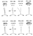
- FIGS. 12A , 12 B, 12 C, and 12 D are diagrams showing aberration characteristics at the wide-angle position in focusing of the infinite object point of the zoom lens in the second embodiment
- FIGS. 12E , 12 F, 12 G, and 12 H are diagrams showing aberration characteristics at the middle position in focusing of the infinite object point of the zoom lens in the second embodiment
- FIGS. 12I , 12 J, 12 K, and 12 L are diagrams showing aberration characteristics at the telephoto position in focusing of the infinite object point of the zoom lens in the second embodiment
- FIGS. 13A , 13 B, 13 C, and 13 D are diagrams showing aberration characteristics at the intermediate point between the wide-angle position and the middle position in focusing of the infinite object point of the zoom lens in the second embodiment;
- FIGS. 13E , 13 F, 13 G, and 13 H are diagrams showing aberration characteristics at the intermediate point between the middle position and the telephoto position in focusing of the infinite object point of the zoom lens in the second embodiment;
- FIG. 14 is a sectional view showing an optical arrangement, developed along the optical axis, of a third embodiment of the zoom lens used in the electronic imaging apparatus according to the present invention.
- FIGS. 15A , 15 B, and 15 C are sectional views showing optical arrangements, developed along the optical axis, at wide-angle, middle, and telephoto positions, respectively, in focusing of the infinite object point of the zoom lens in the third embodiment;
- FIGS. 16A , 16 B, 16 C, 16 D, and 16 E are diagrams showing characteristics of distortion at the wide-angle position, the middle position, the telephoto position, an intermediate point between the wide-angle position and the middle position, and an intermediate point between the middle position and the telephoto position, respectively, in focusing of the infinite object point of the zoom lens in the third embodiment;
- FIGS. 17A , 17 B, 17 C, and 17 D are diagrams showing aberration characteristics at the wide-angle position in focusing of the infinite object point of the zoom lens in the third embodiment
- FIGS. 17E , 17 F, 17 G, and 17 H are diagrams showing aberration characteristics at the middle position in focusing of the infinite object point of the zoom lens in the third embodiment
- FIGS. 171 , 17 J, 17 K, and 17 L are diagrams showing aberration characteristics at the telephoto position in focusing of the infinite object point of the zoom lens in the third embodiment
- FIGS. 18A , 18 B, 18 C, and 18 D are diagrams showing aberration characteristics at the intermediate point between the wide-angle position and the middle position in focusing of the infinite object point of the zoom lens in the second embodiment;
- FIGS. 18E , 18 F, 18 G, and 18 H are diagrams showing aberration characteristics at the intermediate point between the middle position and the telephoto position in focusing of the infinite object point of the zoom lens in the third embodiment;
- FIG. 19 is a sectional view showing an optical arrangement, developed along the optical axis, of a fourth embodiment of the zoom lens according to the present invention.
- FIGS. 20A , 20 B, and 20 C are sectional views showing optical arrangements, developed along the optical axis, at wide-angle, middle, and telephoto positions, respectively, in focusing of the infinite object point of the zoom lens in the fourth embodiment;
- FIGS. 21A , 21 B, 21 C, and 21 D are diagrams showing aberration characteristics at the wide-angle position in focusing of the infinite object point of the zoom lens in the fourth embodiment
- FIGS. 21E , 21 F, 21 G, and 21 H are diagrams showing aberration characteristics at the middle position in focusing of the infinite object point of the zoom lens in the fourth embodiment
- FIGS. 21I , 21 J, 21 K, and 21 L are diagrams showing aberration characteristics at the telephoto position in focusing of the infinite object point of the zoom lens in the fourth embodiment
- FIGS. 22A , 22 B, 22 C, and 22 D are diagrams showing aberration characteristics at the wide-angle position in focusing of a shorter-distance object point of the zoom lens in the fourth embodiment
- FIGS. 22E , 22 F, 22 G, and 22 H are diagrams showing aberration characteristics at the middle position in focusing of the shorter-distance object point of the zoom lens in the fourth embodiment
- FIGS. 22I , 22 J, 22 K, and 22 L are diagrams showing aberration characteristics at the telephoto position in focusing of the shorter-distance object point of the zoom lens in the fourth embodiment
- FIG. 23 is a sectional view showing an optical arrangement, developed along the optical axis, of a fifth embodiment of the zoom lens according to the present invention.
- FIGS. 24A , 24 B, and 24 C are sectional views showing optical arrangements, developed along the optical axis, at wide-angle, middle, and telephoto positions, respectively, in focusing of the infinite object point of the zoom lens in the fifth embodiment;
- FIG. 25 is a sectional view showing an optical arrangement, developed along the optical axis, of a sixth embodiment of the zoom lens according to the present invention.
- FIGS. 26A , 26 B, and 26 C are sectional views showing optical arrangements, developed along the optical axis, at wide-angle, middle, and telephoto positions, respectively, in focusing of the infinite object point of the zoom lens in the sixth embodiment;
- FIGS. 27A , 27 B, 27 C, and 27 D are diagrams showing aberration characteristics at the wide-angle position in focusing of the infinite object point of the zoom lens in the sixth embodiment
- FIGS. 27E , 27 F, 27 G, and 27 H are diagrams showing aberration characteristics at the middle position in focusing of the infinite object point of the zoom lens in the sixth embodiment
- FIGS. 27I , 27 J, 27 K, and 27 L are diagrams showing aberration characteristics at the telephoto position in focusing of the infinite object point of the zoom lens in the sixth embodiment
- FIGS. 28A , 28 B, 28 C, and 28 D are diagrams showing aberration characteristics at the wide-angle position in focusing of the shorter-distance object point of the zoom lens in the sixth embodiment
- FIGS. 28E , 28 F, 28 G, and 28 H are diagrams showing aberration characteristics at the middle position in focusing of the shorter-distance object point of the zoom lens in the sixth embodiment
- FIGS. 28I , 28 J, 28 K, and 28 L are diagrams showing aberration characteristics at the telephoto position in focusing of the shorter-distance object point of the zoom lens in the sixth embodiment
- FIG. 29 is a sectional view showing an optical arrangement, developed along the optical axis, of a seventh embodiment of the zoom lens according to the present invention.
- FIGS. 30A , 30 B, and 30 C are sectional views showing optical arrangements, developed along the optical axis, at wide-angle, middle, and telephoto positions, respectively, in focusing of the infinite object point of the zoom lens in the seventh embodiment;
- FIGS. 31A , 31 B, 31 C, and 31 D are diagrams showing aberration characteristics at the wide-angle position in focusing of the infinite object point of the zoom lens in the seventh embodiment
- FIGS. 31E , 31 F, 31 G, and 31 H are diagrams showing aberration characteristics at the middle position in focusing of the infinite object point of the zoom lens in the seventh embodiment
- FIGS. 31I , 31 J, 31 K, and 31 L are diagrams showing aberration characteristics at the telephoto position in focusing of the infinite object point of the zoom lens in the seventh embodiment
- FIGS. 32A , 32 B, 32 C, and 32 D are diagrams showing aberration characteristics at the wide-angle position in focusing of the shorter-distance object point of the zoom lens in the seventh embodiment
- FIGS. 32E , 32 F, 32 G, and 32 H are diagrams showing aberration characteristics at the middle position in focusing of the shorter-distance object point of the zoom lens in the seventh embodiment
- FIGS. 32I , 32 J, 32 K, and 32 L are diagrams showing aberration characteristics at the telephoto position in focusing of the shorter-distance object point of the zoom lens in the seventh embodiment
- FIG. 33 is a sectional view showing an optical arrangement, developed along the optical axis, of an eighth embodiment of the zoom lens according to the present invention.
- FIGS. 34A , 34 B, and 34 C are sectional views showing optical arrangements, developed along the optical axis, at wide-angle, middle, and telephoto positions, respectively, in focusing of the infinite object point of the zoom lens in the seventh embodiment;
- FIGS. 35A , 35 B, 35 C, and 35 D are diagrams showing aberration characteristics at the wide-angle position in focusing of the infinite object point of the zoom lens in the eighth embodiment
- FIGS. 35E , 35 F, 35 G, and 35 H are diagrams showing aberration characteristics at the middle position in focusing of the infinite object point of the zoom lens in the eighth embodiment
- FIGS. 35I , 35 J, 35 K, and 35 L are diagrams showing aberration characteristics at the telephoto position in focusing of the infinite object point of the zoom lens in the eighth embodiment
- FIGS. 36A , 36 B, 36 C, and 36 D are diagrams showing aberration characteristics at the wide-angle position in focusing of the shorter-distance object point of the zoom lens in the eighth embodiment
- FIGS. 36E , 36 F, 36 G, and 36 H are diagrams showing aberration characteristics at the middle position in focusing of the shorter-distance object point of the zoom lens in the eighth embodiment
- FIGS. 36I , 36 J, 36 K, and 36 L are diagrams showing aberration characteristics at the telephoto position in focusing of the shorter-distance object point of the zoom lens in the eighth embodiment
- FIG. 37 is a sectional view showing an optical arrangement, developed along the optical axis, of a ninth embodiment of the zoom lens according to the present invention.
- FIGS. 38A , 38 B, and 38 C are sectional views showing optical arrangements, developed along the optical axis, at wide-angle, middle, and telephoto positions, respectively, in focusing of the infinite object point of the zoom lens in the ninth embodiment;
- FIG. 39 is a sectional view showing an optical arrangement, developed along the optical axis, of a tenth embodiment of the zoom lens according to the present invention.
- FIGS. 40A , 40 B, and 40 C are sectional views showing optical arrangements, developed along the optical axis, at wide-angle, middle, and telephoto positions, respectively, in focusing of the infinite object point of the zoom lens in the tenth embodiment;
- FIG. 41 is a sectional view showing an optical arrangement, developed along the optical axis, of an eleventh embodiment of the zoom lens according to the present invention.
- FIGS. 42A , 42 B, and 42 C are sectional views showing optical arrangements, developed along the optical axis, at wide-angle, middle, and telephoto positions, respectively, in focusing of the infinite object point of the zoom lens in the eleventh embodiment;
- FIG. 43 is a sectional view showing an optical arrangement, developed along the optical axis, of a twelfth embodiment of the zoom lens according to the present invention.
- FIGS. 44A , 44 B, and 44 C are sectional views showing optical arrangements, developed along the optical axis, at wide-angle, middle, and telephoto positions, respectively, in focusing of the infinite object point of the zoom lens in the twelfth embodiment;
- FIG. 45 is a sectional view showing an optical arrangement, developed along the optical axis, of a thirteenth embodiment of the zoom lens according to the present invention.
- FIGS. 46A , 46 B, and 46 C are sectional views showing optical arrangements, developed along the optical axis, at wide-angle, middle, and telephoto positions, respectively, in focusing of the infinite object point of the zoom lens in the thirteenth embodiment;
- FIG. 47 is a sectional view showing an optical arrangement, developed along the optical axis, of a fourteenth embodiment of the zoom lens according to the present invention.
- FIGS. 48A , 48 B, and 48 C are sectional views showing optical arrangements, developed along the optical axis, at wide-angle, middle, and telephoto positions, respectively, in focusing of the infinite object point of the zoom lens in the fourteenth embodiment;
- FIGS. 49A , 49 B, 49 C, and 49 D are diagrams showing aberration characteristics at the wide-angle position in focusing of the infinite object point of the zoom lens in the fourteenth embodiment
- FIGS. 49E , 49 F, 49 G, and 49 H are diagrams showing aberration characteristics at the middle position in focusing of the infinite object point of the zoom lens in the fourteenth embodiment
- FIGS. 49I , 49 J, 49 K, and 49 L are diagrams showing aberration characteristics at the telephoto position in focusing of the infinite object point of the zoom lens in the fourteenth embodiment
- FIGS. 50A , 50 B, 50 C, and 50 D are diagrams showing aberration characteristics at the wide-angle position in focusing of the shorter-distance object point of the zoom lens in the fourteenth embodiment
- FIGS. 50E , 50 F, 50 G, and 50 H are diagrams showing aberration characteristics at the middle position in focusing of the shorter-distance object point of the zoom lens in the fourteenth embodiment
- FIGS. 50I , 50 J, 50 K, and 50 L are diagrams showing aberration characteristics at the telephoto position in focusing of the shorter-distance object point of the zoom lens in the fourteenth embodiment
- FIG. 51 is a sectional view showing an optical arrangement, developed along the optical axis, of a fifteenth embodiment of the zoom lens used in the electronic imaging apparatus according to the present invention.
- FIGS. 52A , 52 B, and 52 C are sectional views showing optical arrangements, developed along the optical axis, at wide-angle, middle, and telephoto positions, respectively, in focusing of the infinite object point of the zoom lens in the fifteenth embodiment;
- FIGS. 53A , 53 B, 53 C, and 53 D are diagrams showing aberration characteristics at the wide-angle position in focusing of the infinite object point of the zoom lens in the fifteenth embodiment
- FIGS. 53E , 53 F, 53 G, and 53 H are diagrams showing aberration characteristics at the middle position in focusing of the infinite object point of the zoom lens in the fifteenth embodiment
- FIGS. 53I , 53 J, 53 K, and 53 L are diagrams showing aberration characteristics at the telephoto position in focusing of the infinite object point of the zoom lens in the fifteenth embodiment
- FIGS. 54A , 54 B, 54 C, and 54 D are diagrams showing aberration characteristics at the wide-angle position in focusing of the shorter-distance object point of the zoom lens in the fifteenth embodiment
- FIGS. 54E , 54 F, 54 G, and 54 H are diagrams showing aberration characteristics at the middle position in focusing of the shorter-distance object point of the zoom lens in the fifteenth embodiment
- FIGS. 54I , 54 J, 54 K, and 54 L are diagrams showing aberration characteristics at the telephoto position in focusing of the shorter-distance object point of the zoom lens in the fifteenth embodiment
- FIG. 55 is a sectional view showing an optical arrangement, developed along the optical axis, of a sixteenth embodiment of the zoom lens used in the electronic imaging apparatus according to the present invention.
- FIGS. 56A , 56 B, and 56 C are sectional views showing optical arrangements, developed along the optical axis, at wide-angle, middle, and telephoto positions, respectively, in focusing of the infinite object point of the zoom lens in the sixteenth embodiment;
- FIGS. 57A , 57 B, 57 C, and 57 D are diagrams showing aberration characteristics at the wide-angle position in focusing of the infinite object point of the zoom lens in the sixteenth embodiment
- FIGS. 57E , 57 F, 57 G, and 57 H are diagrams showing aberration characteristics at the middle position in focusing of the infinite object point of the zoom lens in the sixteenth embodiment
- FIGS. 57I , 57 J, 57 K, and 57 L are diagrams showing aberration characteristics at the telephoto position in focusing of the infinite object point of the zoom lens in the sixteenth embodiment
- FIGS. 58A , 58 B, 58 C, and 58 D are diagrams showing aberration characteristics at the wide-angle position in focusing of the shorter-distance object point of the zoom lens in the sixteenth embodiment
- FIGS. 58E , 58 F, 58 G, and 58 H are diagrams showing aberration characteristics at the middle position in focusing of the shorter-distance object point of the zoom lens in the sixteenth embodiment
- FIGS. 58I , 58 J, 58 K, and 58 L are diagrams showing aberration characteristics at the telephoto position in focusing of the shorter-distance object point of the zoom lens in the sixteenth embodiment
- FIGS. 59A , 59 B, and 59 C are explanatory views showing preferred arrangements of the last lens units and filters in the electronic imaging apparatus of the present invention.
- FIG. 60 is a perspective front view showing a digital camera incorporating a path bending zoom lens of the present invention in a photographing optical system
- FIG. 61 is a perspective rear view showing the digital camera of FIG. 60 ;
- FIG. 62 is a sectional view showing the internal structure of the digital camera of FIG. 60 ;
- FIG. 63 is a perspective front view showing a personal computer in which the path bending zoom lens of the present invention is incorporated as an objective optical system;
- FIG. 64 is a sectional view showing the photographing optical system incorporated in the personal computer of FIG. 63 ;
- FIG. 65 is a side view showing the personal computer of FIG. 63 ;
- FIG. 66A is a front view showing a mobile phone in which the path bending zoom lens of the present invention is incorporated as the photographing optical system;
- FIG. 66B is a side view showing the mobile phone of FIG. 66A ;
- FIG. 66C is a sectional view showing the mobile phone of FIG. 66A .
- the zoom lens in the electronic imaging apparatus mounting the zoom lens of a high zoom ratio and small F-number, a slim design relating to the depth and a wide angle of view are made compatible.
- the zoom lens having the focal length in the proximity of the wide-angle position, is constructed so that an image with large-barrel distortion is intentionally formed on the electronic image sensor. By doing so, the information of the wide angle of view can be acquired without rendering the optical system bulky.
- the barrel-distorted image is photoelectrically converted through the image sensor into image data.
- the image data are electrically corrected and processed, corresponding to a shape change (image distortion), through a signal processing system incorporated in the electronic imaging apparatus. That is, the image data output from the electronic imaging apparatus contain image distortion, which is digitally corrected. By doing so, when the image data secured through the image sensor are reproduced on a display device, an image very similar to the object is finally obtained.
- FIG. 1 An example of the correction is shown in FIG. 1 .
- points located inside the circle of the radius R should be corrected toward the center of the circle R. Thus, these pints are moved toward the center of the circle.
- Points located outside the circle of the radius R should be corrected toward the exterior of the circle. Thus, these points are moved toward the exterior of the circle.
- a point P 1 on the circle of a radius r 1 ( ⁇ ) is located inside the circle of the radius R.
- the point P 1 is moved to a point P 2 on the circle of a radius r 1 ′( ⁇ ) ( ⁇ the radius r 1 ( ⁇ ).
- a point Q 1 on the circle of a radius r 2 ( ⁇ ) is located outside the circle of the radius R.
- the point Q 1 is moved to a point Q 2 on the circle of a radius r 2 ′( ⁇ ) (> the radius r 2 ( ⁇ )).
- a point situated inside the circle of the radius R may be moved toward the exterior of the circle.
- a point situated outside the circle of the radius R may be moved toward the interior of the circle. How the point is moved varies with the image distortion.
- the optical system is rotationally symmetrical about the optical axis.
- distortion is also produced rotationally symmetrical about the optical axis.
- the magnification on the circle (image height) of the radius R coming into contact with the major sides of the effective imaging surface is made constant, with an intersection of the optical axis and the imaging surface as a center, on a reproduced image.
- individual points on the circles (image heights) of the radii r( ⁇ ) other than the circle of the radius R are almost radially moved.
- the individual points are moved concentrically so that the radii r( ⁇ ) become radii r′( ⁇ ).
- an optical image when formed by the electronic image sensor, ceases to be continuous. This is because the optical image is sampled by individual pixels of the electronic image sensor. Therefore, unless the pixels of the electronic image sensor are radially arrayed, the circle of the radius R drawn on the optical image ceases to be accurate at all. That is, when the image data are indicated by individual points of discrete coordinates, there is no circle that the magnification can be made constant in the shape correction of the image data. It is thus good practice to use a method of determining coordinates (Xi′, Yj′) of moved points in accordance with pixels (Xi, Yj).
- Such a method is particularly effective for correction when considerable image distortion is produced with respect to the optical axis because of manufacturing errors of the optical system and the electronic image sensor.
- the circle of the radius R drawn on the optical image becomes asymmetrical, correction for determining the coordinates of moved points in accordance with the pixels is effective.
- geometrical distortion is sometimes produced when a signal is reproduced on the image.
- the above method is effective.
- the prism can be further downsized and a further slim design of the electronic imaging apparatus is possible. In this case also, this correcting method is effective.
- the electronic imaging apparatus of the present invention there is the need to calculate the amount of correction, r′( ⁇ ) ⁇ r( ⁇ ).
- the relationship between the radius r( ⁇ ), namely the half angle of view and the image height or between a real image height r and an ideal image height r′/ ⁇ is recorded in a recording medium housed in the electronic imaging apparatus.
- the amount of light does not suffer a serious shortage at both ends of the minor sides.
- the radius R satisfies the following condition: 0 ⁇ R ⁇ 0.6 Ls where Ls is the length of the minor side of the effective imaging surface.
- the radius R preferably satisfies the following condition: 0.3 Ls ⁇ R ⁇ 0.6 Ls
- a focal-length section requiring correction is divided into some focal zones.
- the amount of correction may be evenly multiplied by the coefficient in accordance with the focal length to obtain the final amount of correction.
- the following condition determines the extent of barrel distortion at the wide-angle position in the zoom optical system. It is desirable to satisfy this condition.
- fw is the focal length of the entire zoom optical system at the wide-angle position
- y 07 is an image height expressed by 0.7 ⁇ y 10
- y 10 is a distance (the maximum height) from the center to a point farthest therefrom on the effective imaging surface (in a plane where imaging is possible) of an electronic image sensor
- ⁇ 07w is an angle made by a direction of an object point with an optical axis, where the object point corresponds to an image point that is at the point y 07 away from the center on the effective imaging surface of the electronic image sensor at the wide angle position.
- ⁇ 07w is an angle on the object side, made by the chief ray passing through the point of the image height y 07 with the optical axis, that is, an angle made by the chief ray directed toward the position of the front principal point of the zoom optical system from the object side with the optical axis.
- the zoom optical system satisfies Condition (1)
- the compact design of the optical system is maintained and at the same time, an image can be obtained over a wide field of view. Furthermore, when the image is processed through the signal processing system incorporated in the electronic imaging apparatus, image distortion caused by aberration of the optical system can be corrected without increasing an enlargement ratio in a radial direction on an image periphery or recognizing the deterioration of sharpness on the image periphery.
- distortion is intentionally produced in the optical system, and the image, after being formed by the electronic image sensor, is electrically processed so that distortion is corrected. This is done for the purpose of fulfilling the compact design and the wide-angle design (an angle of view of 38° or more in a vertical direction, allowing for distortion). In the present invention, therefore, it is also important that the optical system is chosen so that it does not have unnecessary size.
- the lens unit for changing the magnification of the zoom optical system is located on the image side of the aperture stop.
- the effective imaging area of the image sensor is narrowed and the focal length of the optical system is reduced.
- the zoom optical system has the power corresponding to a so-called retrofocus system that a front lens unit has negative refracting power and a rear lens unit has positive refracting power.
- a lens unit B (a moving lens unit) having the positive refracting power to change the magnification is placed on the image side of the apertures stop, and when the magnification is changed in the range from the wide-angle position to the telephoto position, this moving lens unit is moved in only one direction (toward the object side to increase the magnification) without changing its direction.
- the zoom optical system satisfies Condition (2), there is no need to locate the entrance pupil of the zoom optical system farther away from the object side. Moreover, the fluctuation of aberration in the magnification change is suppressed and imaging performance can be ensured.
- the lens unit is located on the object side of the aperture stop, or when the lens unit (a lens unit I) is located at the most object-side position, bulkiness of the diameter and depth of the lens unit is prevented and at the same time, the angle of view can be ensured.
- correction for distortion need not be made over all the zoom area and may be made only in the proximity of the wide-angle position where barrel distortion is particularly increased.
- the lens unit B has positive refracting power, and is simply moved toward the object side when the magnification is changed in the range from the wide-angle position to the telephoto position.
- Relative decentration sensitivities of lenses constituting the lens unit B tend to increase.
- the lens unit B includes a negative lens and an adjacent positive lens on the object side thereof, the relative decentration sensitivities of both lenses become considerably high.
- the lens unit B has a cemented lens component of a positive lens and a negative lens, arranged in this order from the object side.
- R B1 is the radius of curvature of the most object-side surface of the cemented lens component in the lens unit B and R B3 is the radius of curvature, on the optical axis, of the most image-side surface of the cemented lens component in the lens unit B.
- the lens unit B includes a single positive lens on the object side of the cemented lens component and has the lens arrangement of two lens components composed of three lens elements as a whole.
- the lens unit B preferably includes not more than two optical elements with negative refracting power and has not more than three lens elements as a whole.
- the lens unit I is designed to include at least one optical element with negative refracting power, having at least one aspherical surface.
- an optical element with negative refracting power is placed at the most object-side position of the lens unit I.
- the surface profile of the optical element it is desirable to satisfy the following condition: ⁇ 0.5 ⁇ ( R 11 + R 12 )/( R 11 ⁇ R 12 ) ⁇ 1.1 (6) where R 11 is the radius of curvature of the entrance surface of the optical element with negative refracting power and R 12 is the radius of curvature of the exit surface of the optical element with negative refracting power.
- the present invention in order to achieve the wide-angle design, barrel distortion is positively produced.
- the present invention is constructed so that this produced aberration is electrically corrected. It is thus desirable that the value of (R 11 +R 12 )/(R 11 ⁇ R 12 ) is relatively low since a double effect relative to the compact design and the wide-angle design can be brought about.
- Condition (6) When Condition (6) is satisfied, the extent of barrel distortion at the wide-angle position of the zoom optical system satisfies Condition (1) and the effects of the compact design and the wide-angle design can be secured without lessening the effect of locating the entrance pupil close to the object side.
- bending of the optical path (optical axis) of the imaging optical system can be used.
- the optical path is bent on the object side of the imaging optical system as far as possible, the effect of reducing the depth is heightened.
- the lens unit I has a reflecting optical element for bending the optical path and satisfies the following condition: 0.3 ⁇ d F /d p ⁇ 0.7 (7)
- d F is a distance from an intersection of the most object-side surface of the lens unit I with the optical axis to an intersection of the first reflecting surface with the optical axis
- d P is a distance, measured along the optical axis, from an intersection of the most object-side refracting surface (an entrance surface in a prism) relative to the reflecting surface with the optical axis to an intersection of the most image-side refracting surface (an exit surface in the prism) relative to the reflecting surface with the optical axis.
- the reflecting surface is located on the object side of the lens unit I as far as possible.
- the entrance pupil will be located farther away from the most object-side surface of the imaging optical system.
- the reflecting optical element for bending the optical path is constructed with a prism, it is good practice to configure its entrance surface to be concave.
- this prism is located at the most object-side position in the lens unit I and satisfies the following condition: ⁇ 7 ⁇ R 11 / y 10 ⁇ 1.5 (8) where R 11 is the radius of curvature, on the optical axis, of the most object-side surface of the lens unit I and y 10 is a distance (the maximum image height) form the center to a point farthest therefrom on the effective imaging surface (in a plane where imaging is possible) of the electronic image sensor.
- Condition (8) it is avoidable that the negative refracting power on the object side of the position of path bending is lessened and the entrance pupil is located far away from the object side. As a result, bulkiness of the prism can be suppressed. Furthermore, since a ray height can be lowered on the image side of the prism, bulkiness of succeeding lenses and an increase of a stop diameter can be suppressed. Consequently, the depth of the camera can be reduced.
- the refractive index of the medium of the prism in the d line should be high, preferably at least 1.68 and ideally at least 1.75.
- the entrance surface of the prism is configured as an aspherical surface that curvature is moderated progressively in going from the optical axis to the periphery. Moreover, in the radius of curvature on the optical axis, it is desirable to satisfy the following condition: ⁇ 0.70 ⁇ fw ⁇ ( n 1 ⁇ 1)/ R 11 ⁇ 0.20 (9) where n 1 is the refractive index (reference wavelength) of the medium of the prism.
- Condition (9) When Condition (9) is satisfied, the curvature is not very strong and the deterioration of off-axis aberrations can be prevented.
- the entrance pupil is not located far away from the object side, and a tendency toward bulkiness of the prism can be repressed.
- a driving mechanism is indispensable for the zoom lens. Even though the optical system is downsized, a complicated and oversized driving mechanism is meaningless. In the electronic imaging apparatus of the present invention, the depth is reduced as one purpose. Thus, it is undesirable that the diameter of the zoom lens including the driving mechanism (which is hereinafter referred to as a zoom lens unit) is increased.
- the lens unit I has positive refracting power as a whole.
- a lens unit II with negative refracting power which is moved along the optical axis and thereby exercises a variable magnification function, is placed on the image side of the lens unit 1 , followed by the lens unit B on the image side thereof.
- variable magnification function is shared between the lens unit II and the lens unit B, and thus the amount of movement of each of the lens units is decreased.
- the lens unit II and the lens unit B which have refracting powers of mutually different signs, are moved on opposite directions when the magnification changed.
- the aperture stop and a shutter are interposed between the lens unit II and the lens unit B, there is no need to move the aperture stop and the shutter when the magnification is changed.
- the aperture diameter can be made small.
- the lens unit I with positive refracting power, it is desirable that the ray height is kept to a minimum to obviate oversizing and aberrations can be favorably corrected.
- the lens unit I is preferably constructed to include, in order from the object side, a reflecting optical element for bending the optical path, with an entrance surface configured as a concave surface facing the object side and a positive lens.
- the entrance surface of the reflecting optical element is configured as an aspherical surface that curvature is moderated progressively in going from the optical axis to the periphery.
- the positive lens like the reflecting optical element, is such that at least one surface is configured as an aspherical surface that curvature is moderated progressively in going from the optical axis to the periphery.
- the decentration sensitivity is liable to be increased.
- the lens unit I is fixed when the magnification is changed.
- the lens unit moved for focusing (called a lens unit F) is placed on the image side of the lens unit B.
- the lens unit F may be placed as the most image-side lens unit, but another fixed lens unit (called a lens unit C) may be provided on the image side thereof.
- the lens unit I when having positive refracting power, is constructed with two elements, a prism and a positive lens, arranged in this order from the object side.
- This prism has the entrance surface configured as an aspherical concave surface and includes a reflecting surface for bending the optical path.
- the prism preferably has negative refracting power so that it particularly satisfies at least one of Conditions (9), (9′), and (9′′). By doing so, the entrance pupil is located close to the object side and compactness of the prism can be kept.
- the lens unit I is required to have the highest possible refractive index as a whole. In this case, it is desirable to satisfy the following condition: 2.0 ⁇ f 1 /fw ⁇ 10.0 (10) where f 1 is the focal length of the whole of the lens unit I.
- Condition (10) When Condition (10) is satisfied, the difficulty of correction for off-axis aberration or chromatic aberration and bulkiness of the prism are avoidable, the variable magnification ratio of the lens unit II can be increased.
- the positive lens placed in the lens unit I is designed to satisfy Condition (11) described below. By doing so, the ratio of the refractive index to the height of a transmitted off-axis ray can be increased. At the same time, it is desirable that the shape of the positive lens satisfies Condition (12) described below.
- Condition (11) it is avoidable that the variable magnification ratio of the lens unit II becomes low for the amount of movement and the optical system is bulky. Moreover, it is also avoidable that correction for off-axis aberration, such as astigmatism, becomes difficult.
- Condition (12) a tendency that the principal point of the lens unit I is located on the image side is not exhibited, and the variable magnification efficiency of the lens unit II can be favorably maintained. Furthermore, the production of coma can be suppressed, and interference with the lens unit II does not occur because the lens unit I does not assume a meniscus shape of strong curvature.
- the lens unit II is constructed with two lenses, a negative lens and a positive lens, arranged in this order from the object side. It is further desirable that at least one surface of this negative lens is configured as an aspherical surface and in addition, the negative lens satisfies the following condition: ⁇ 1.0 ⁇ ( R 2NF +R 2NR )/( R 2NF ⁇ R 2NR ) ⁇ 1.0 (13) where R 2NF is the radius of curvature, on the optical axis, of the object-side surface of the negative lens in the lens unit II and R 2NR is the radius of curvature, on the optical axis, of the image-side surface of the negative lens in the lens unit II.
- Condition (13) When Condition (13) is satisfied, the production of coma and barrel distortion can be suppressed.
- an optical low-pass filter applicable to the electronic imaging apparatus of the present invention.
- an optical low-pass filter taking advantage of birefringence is usually interposed between the imaging optical system and the electronic image sensor.
- this arrangement offers an obstacle to the compact design and correction for aberration. It is thus desirable to use the optical low-pass filter of the smallest possible thickness.
- ne is the refractive index of the birefringent optical element relative to the extraordinary ray and no is the refractive index of the birefringent optical element relative to the ordinary ray.
- the thickness is moderated, which is suitable for the compact design.
- the optical low-pass filter capable of completely transmitting visible light can be realized.
- the optical low-pass filter is required to prevent the production of aliasing.
- the aliasing is the phenomenon occurring when the imaging optical system possesses a vast number of components over the Nyquist rate. However, when the pixel size is moderately reduced, the components over the Nyquist rate are eliminated due to diffraction.
- Fw is an exposure F value at the wide-angle position and a is a pixel-to-pixel distance (in micrometers) in a horizontal direction of the image sensor. More specifically, it is dimensionless.
- the pixel-to-pixel distance may be a pixel pitch.
- the optical low-pass filter becomes necessary.
- the optical low-pass filter is preferably constructed as described below to have the smallest possible thickness.
- the optical low-pass filter takes advantage of a birefringence function of a uniaxial crystal such as quartz.
- the optical low-pass filter is constructed with one uniaxial crystal (a crystal having the birefringence function) or a plurality of uniaxial crystals.
- individual crystals constitute the optical low-pass filter.
- an angle made by the crystal axis with the optical axis of the zoom lens varies from 35° to 55°.
- the optical low-pass filter when constructed with the plurality of uniaxial crystals, is such that directions where individual crystal axes are projected on an image plane are different.
- a thickness t LPF (mm) of the optical low-pass filter satisfies the following conditions:
- t LPF (mm) is the largest thickness of an optical low-pass filter, measured along the optical axis, having one crystal axis within the range that the angle made with the optical axis of the zoom lens varies from 35° to 55°.
- an optical low-pass filter of the largest thickness is set with respect to the thickness so that contrast theoretically becomes zero by the Nyquist limited rate.
- the thickness in this case is approximately a/5.88 (mm). Beyond the value of a/5.88 (mm), the effect of preventing false signals such as moiré fringes is brought about, but the resolution of the image sensor ceases to be completely applicable. Below the value of a/5.88 (mm), false signals such as moiré fringes cannot be completely eliminated.
- the false signals such as moiré fringes have a close relationship with the imaging performance of a photographic lens such as the zoom lens.
- the imaging performance is high, the false signals such as moiré fringes are liable to be produced. Consequently, it is favorable that the thickness of the optical low-pass filter is set to be somewhat large when the imaging performance is high, and to be somewhat small when it is not very high.
- the thickness is made several to several tens of percent smaller than the value of a/5.88 (mm).
- the preset spatial frequency refers to a spatial frequency below the frequency corresponding to the Nyquist limit.
- One of these approaches is to set an angle made by the crystal axis of the optical low-pass filter with the optical axis of the zoom lens in the range from 15 to 35 degrees or from 55 to 75 degrees.
- the amount of separation of incident light into the ordinary ray and the extraordinary ray is less than in the proximity of 45 degrees.
- the incident light ceases to separate into the ordinary ray and the extraordinary ray (however, at 90 degrees, a velocity difference is produced between both rays, resulting in a phase difference . . . the principle of the quarter-wave plate).
- Another approach is to eliminate the optical low-pass filter, as the case may be.
- the optical low-pass filter may be eliminated.
- the pixel pitch is small and imaging performance in opening is best, it is not necessary to use a method of replacing a variable inside-diameter stop or a different inside-diameter stop as a means of restricting the size of a light beam incident on the imaging surface. It is good practice, for example, to use a fixed inside-diameter aperture stop and to provide a variable transmittance means at any place in the optical path.
- variable transmittance means When the variable transmittance means is introduced into the optical path, there is a method of use an optical element whose transmittance is different.
- an optical element whose transmittance can be changed by a voltage, like an electrochromic element may be used.
- FIG. 3 shows spectral transmittance characteristics of the electrochromic element.
- the ratio between a maximum transmittance ⁇ max ( ⁇ 0.7) at a wavelength of 520 nm and a minimum transmittance ⁇ min ( ⁇ 0.3) should be at least 2.5, preferably at least 3.5.
- the spectral transmittance satisfies the following conditions: ⁇ 440/ ⁇ 520>0.7 (18) ⁇ 600/ ⁇ 520>0.8 (19) where ⁇ x (x is a numeral) is a transmittance at a wavelength of x nm.
- the optical low-pass filter is placed on the image side of the most image-side lens unit of the imaging lens unit.
- the optical low-pass filter is extremely thin and thus a strength problem arises. Therefore, it is favorable that the image-side surface of a lens located at the most image-side position is configured as a flat surface, to which the optical low-pass filter is cemented.
- the optical low-pass filter may be cemented to the cover glass of the image sensor.
- the electrochromic element mentioned above is available.
- the electrochromic element is such that a substance in which a chemical change is electrically carried out to vary the transmittance is sandwiched between two glass base plates having transparent electrodes. It is good practice to locate such a variable transmittance optical element at any place of the optical path. In this case, it is desirable that the electrochromic element is placed on the image side of the lens unit F moved for focusing, described above.
- one of the two glass base plates of the variable transmittance optical element may be substituted with an optical element having flat surfaces.
- the two glass base plates may be substituted with a lens having flat surfaces and the optical low-pass filter.
- the infrared cutoff filter In the electronic imaging apparatus, an infrared absorbing filter of constant thickness is usually introduced into the optical path on the object side of the image sensor so that infrared light is not incident on the imaging surface.
- the infrared absorbing filter is replaced with a coating having no thickness to speak of, in order to render the optical system short or thin in the electronic imaging apparatus.
- the optical system is, of course, made thin accordingly, the secondary effect to be described below is brought about.
- a near-infrared sharp cutoff coating in which the transmittance at a wavelength of 600 nm is 80% or more and the transmittance at a wavelength of 700 nm is 8% or less is introduced into the optical path on the object side of the image sensor located behind the zoom lens. Then, the transmittance in the near-infrared region of wavelengths more than 700 nm is lower than that of the absorption-type filter and the transmittance on the red side becomes relatively high. In this case, a gain adjustment moderates the defect of a tendency to magenta on the blue-violet side, caused by the solid-state image sensor, such as a CCD, having a complementary color mosaic filter.
- Another defect of the solid-state image sensor such as the CCD is that sensitivity to a wavelength of 550 nm in the near-ultraviolet region is considerably higher than that of the human eye. This brings about remarkable blurring of color at the edge of an image due to chromatic aberration in the near-ultraviolet region. In particular, it is fatal when the optical system is downsized.
- an absorbing body or a reflecting body such that the ratio of the transmittance ( ⁇ 400) at a wavelength of 400 nm to the transmittance ( ⁇ 550) at a wavelength of 550 nm is 0.08 or less and the ratio of the transmittance ( ⁇ 440) at a wavelength of 440 nm to the transmittance ( ⁇ 550) at a wavelength of 550 nm is 0.4 or more is preferably introduced in the optical path.
- these filters are interposed between the imaging optical system and the image sensor.
- the complementary color filter because of its high energy of transmitted light, is higher in substantial sensitivity than in the CCD with the primary color filter and is more advantageous for resolution. Consequently, there is a great merit where a small-sized CCD is used.
- the above conditions and arrangements are properly combined, and thereby more favorable electronic imaging apparatuses can be constructed.
- only the upper of lower limit may be restricted by the upper or lower limit corresponding to a more favorable condition.
- the corresponding value of the condition in each of the embodiments to be described later may be set to the upper limit or the lower limit.
- the optical system suitable for the imaging apparatus which is small in depth, when an attempt is made to ensure imaging performance and a wide angle of view, the optical system is designed to have arrangements described below. One of them is to reduce the number of constituent lenses as far as possible. Another is to bend the optical path on the entrance side of the optical system as far as possible.
- a first lens unit with positive refracting power is placed on the most object-side position
- a second lens unit with negative refracting power is placed on the image side of the first lens unit
- a third lens unit with positive refracting power is placed on the image side of the second lens unit.
- the aspherical surfaces it is favorable to adopt any of the ways that (1) at least two surfaces are placed in a first lens unit G 1 , (2) at least four surfaces are placed in a lens unit combining a second lens unit G 2 with a third lens unit G 3 , (3) at least four surfaces are placed in a lens unit combining the first lens unit G 1 with the second lens unit G 2 , (4) at least two surfaces are placed in each of the first lens unit G 1 and the third lens unit G 3 , (5) at least two surfaces are placed in each of the second lens unit G 2 and the third lens unit G 3 , and (6) three third lens units, each having at least two surfaces, are placed.
- Two aspherical surfaces may be introduced into each of the three lens units.
- the aspherical surfaces are introduced into a divergent surface and a convergent surface, placed in this order from the object side.
- the second lens unit G 2 they are introduced into only a negative lens
- the third lens unit G 3 they are introduced into only a positive lens.
- the first lens unit G 1 should include, in order from the object side along the optical path, an optical element with divergence and a positive lens, arranged as two elements.
- the second lens unit G 2 should include, in order from the object side along the optical path, a biconcave lens and a positive lens.
- the third lens unit G 3 should include, in order from the object side along the optical path, a single positive lens and a lens component of a positive lens and a negative lens with a concave surface of strong power facing the image side, arranged as two lens components composed of three lens elements.
- a movable lens unit is placed, as a fourth lens unit G 4 (the focusing lens unit F), on the image side of the third lens unit G 3 .
- the second lens unit G 2 and the third lens unit G 3 it is desirable that their magnifications satisfy the following conditions: ⁇ 1.0 ⁇ 2 W ⁇ 0.4 (24) ⁇ 1.0 ⁇ 3 W ⁇ 0.4 (25) where ⁇ 2 W is the magnification of the second lens unit G 2 at the wide-angle position and ⁇ 3 W is the magnification of the third lens unit G 3 at the wide-angle position.
- Condition (24) the variable magnification ratio due to the movement of the second lens unit G 2 is liable to be decreased. Beyond the upper limit, the variable magnification ratio due to the movement of the third lens unit G 3 is liable to be decreased.
- the magnification of the third lens unit G 3 is as in Condition (25).
- the fourth lens unit G 4 may be moved in the magnification change.
- a movement limit including the movement in the magnification change satisfies the following condition: 0.8 ⁇ 10 2 ⁇ M 4 ⁇ S 1 ⁇ 6.0 ⁇ 10 2 (26) where M 4 is a difference between a distance where the fourth lens unit G 4 is located at the most object-side position in any state and a distance where it is located at the most image-side position and S 1 is a distance (mm) from an object focused when the fourth lens unit G 4 is located at the most object-side position to the entrance surface of the optical system.
- the last lens unit may be located at the most image-side position of the optical system so that the position of the lens unit is practically fixed with respect to the image plane. It is favorable that the last lens unit is constructed with a single lens and satisfies the following condition: ⁇ 0.10 ⁇ fw/fR ⁇ 0.50 (27) where fR is the focal length of the last lens unit.
- one of methods of reducing the depth of the electronic imaging apparatus is to bend the optical path on the entrance side of the optical system as far as possible.
- the first lens unit G 1 is practically fixed with respect to the image plane.
- the optical element with divergence in the first lens unit G 1 is located at the most object-side position.
- a prism which has an entrance surface configured as a concave surface facing the object side and a reflecting surface for bending the optical path is suitable. It is desirable that the entrance surface is configured as an aspherical surface that divergence is impaired progressively in going from the optical axis to the periphery. It is also desirable that the object-side surface of the positive lens located on the image side thereof is configured as the aspherical surface.
- one or both surfaces of the negative lens should be aspherical.
- one or both surfaces of the positive lens should be aspherical.
- the first lens unit G 1 satisfies the following conditions: 33 ⁇ 12 ⁇ 75 (30) 1.55 ⁇ n 12 (31) where ⁇ 12 is the Abbe's number of the medium of the positive lens in the first lens unit G 1 and n 12 is the refractive index of the medium of the positive lens in the first lens unit G 1 .
- the aperture stop is interposed between the second lens unit G 2 and the third lens unit G 3 so that its position is fixed with respect to the image plane.
- the lens system on the object side of the aperture stop is preferably constructed with one prism and three or less single lenses. By doing so, the entrance pupil is located as close to the object side as possible and the area of path bending can be downsized.
- the second lens unit G 2 and the third lens unit G 3 are adjacent to each other, with the aperture stop between them.
- D 2 is a distance, measured along the optical axis, from the vertex of the most image-side surface of the second lens unit G 2 to the aperture stop at the wide-angle position
- D 3 is a distance, measured along the optical axis, from the aperture stop to the vertex of the most object-side surface of the third lens unit G 3 at the wide-angle position
- the aspherical surfaces are preferably introduced into the negative lens in the second lens unit G 2 with negative refracting power and the positive lens in the third lens unit G 3 with positive refracting power. Whereby, the fluctuation of aberration due to the movement of the second lens unit G 2 and the third lens unit G 3 in the magnification change can be minimized.
- Each of the second lens unit G 2 and the third lens unit G 3 is preferably provided with two aspherical surfaces. It is more desirable to satisfy the following condition: 0.60 ⁇ D 3 / D 2 ⁇ 1.30 (32′)
- the entrance surface is configured as the divergent surface and thus has the shape that a concave surface faces the object side.
- its power is strong. Consequently, barrel distortion is liable to occur.
- the ray height of incident light is decreased for the angle of view. It is thus possible that the prism is rendered small.
- the optical system satisfies the following conditions: 0.75 ⁇ y 07 /( fw ⁇ tan ⁇ 07w ) ⁇ 0.96 (33) 1.0 ⁇ fw/y 10 ⁇ 2.1 (34)
- the zoom lens according to the present invention includes, in order from the object side along the optical path, a first lens unit with positive refracting power, having a reflecting surface for bending the optical path; a first moving lens unit with negative refracting power; and a second moving lens unit simply moved toward the object side when the magnification of the zoom lens is changed in the range from the wide-angle position to the telephoto position.
- the zoom lens can be constructed to satisfy the following conditions at the same time: ⁇ 1.0 ⁇ 2 W ⁇ 0.40 (35) ⁇ 1.0 ⁇ 3 W ⁇ 0.40 (36) where ⁇ 2 W is the magnification of the first moving lens unit at the wide-angle position and ⁇ 3 W is the magnification of the second moving lens unit at the wide-angle position.
- Condition (35) the variable magnification ratio due to the movement of the first moving lens unit is liable to be decreased. Beyond the upper limit, the variable magnification ratio due to the movement of the second moving lens unit is liable to be decreased.
- the magnification of the second moving lens unit is as in Condition (36).
- the zoom lens according to the present invention comprises, in order from the object side along the optical path, a first lens unit with positive refracting power, a first moving lens unit with negative refracting power, an aperture stop practically fixed with respect to the image plane, and a second moving lens unit simply moved toward the object side when the magnification of the zoom lens is changed in the range from the wide-angle position to the telephoto position.
- the first lens unit is practically fixed with respect to the image plane and includes, in order from the object side along the optical path, an optical element which has an entrance surface configured as a concave surface facing the object side and a reflecting surface for bending the optical path and a positive lens.
- the first moving lens unit includes, in order from the object side along the optical path, a biconcave lens and a positive lens.
- the second moving lens unit includes, in order from the object side along the optical path, a single positive lens and a cemented lens component of a positive lens and a negative lens with a concave surface of strong power facing the image side.
- the optical path is bent by the reflecting optical element located at the most object-side position.
- the advantage of the zoom lens is that the thickness corresponding to the depth is kept to a minimum.
- the position of the stop is fixed with respect to the image plane, and hence there is no need to provide space for moving the stop and the shutter actuator in the magnification change.
- the lens unit located at the most object-side position has the positive refracting power, the diameter of the aperture stop is small for the F value and shutter blades require a minimum of relief space.
- the zoom lens has a great advantage that the thickness of the optical system after bending is also kept to a minimum.
- each of the lens units is designed to include, in order from the object side along the optical path, a divergent lens component and a convergent lens component.
- the optical system is constructed with only four parts in a combination of the first lens unit with the first moving lens unit.
- an image point relative to a combination system of the first lens unit and the first moving lens unit that is, an object point relative to a combination system behind the second moving lens unit
- the magnification of the combination system behind the second moving lens unit tends to decrease. This exhibits a tendency that it is hard to increase the magnification for the movement of the lens unit.
- it is favorable that the second moving lens unit has the strongest possible power and the principal point is located as close to the object side as possible.
- the second moving lens unit is designed to include a positive lens, a positive lens, and a negative lens.
- the negative lens of a high decentration sensitivity is cemented to the positive lens located immediately before the negative lens.
- the negative lens is configured as a biconcave lens.
- the reflecting optical element is designed to have the smallest possible size.
- the power of each of the divergent lens component and the convergent lens component of the first lens unit is strengthened. Consequently, distortion and coma are liable to occur.
- it is desirable that the entrance surface of the optical element and one convergent surface of the positive lens in the first lens unit are configured as aspherical surfaces in which curvature is moderated progressively in going from the optical axis to the periphery. Also, correction for distortion will be described later.
- the amount of movement of the first moving lens unit is made much smaller than that of the second moving lens unit.
- the first moving lens unit and the second moving lens unit are adjacent to each other, with the stop between them. It is thus desirable to satisfy the following condition: 0.5 ⁇ D 3 / D 2 ⁇ 1.4 (39) where D 2 is a distance, measured along the optical axis, from the vertex of the most image-side surface of the first moving lens unit to the aperture stop at the wide-angle position and D 3 is a distance, measured along the optical axis, from the aperture stop to the vertex of the most object-side surface of the second moving lens unit at the wide-angle position.
- the F value is liable to increase.
- the prism configured as the reflecting optical element is liable to become bulky.
- the aspherical surfaces are preferably introduced into the negative lens in the first moving lens unit with negative refracting power and the positive lens in the second moving lens unit with positive refracting power. Whereby, the fluctuation of aberration due to the movement of the first moving lens unit and the second moving lens unit in the magnification change can be minimized.
- Each of the first moving lens unit and the second moving lens unit is preferably provided with two aspherical surfaces.
- a focusing lens unit is placed on the image side of the second moving lens unit.
- This focusing lens unit can be moved in focusing.
- the smallest possible area is moved for focusing in the whole range of the magnification change.
- the focus actuator can be downsized significantly. It is thus desirable to satisfy the following condition: 0.8 ⁇ 10 2 ⁇ M 4 ⁇ S 1 ⁇ 6.0 ⁇ 10 2 (40) where M 4 is a difference between a distance where the focusing lens unit is located at the most object-side position in any state and a distance where it is located at the most image-side position and S 1 is a distance (mm) from an object focused when the focusing lens unit is located at the most object-side position to the entrance surface of the optical system.
- a lens unit closest to the image plane may be placed so that its position is fixed with respect to the image plane. This lens unit is different from the focusing lens unit.
- the lens unit may also be provided with a filter and coated with an infrared cutoff coating.
- the entrance surface is configured as the divergent surface and thus has the shape that a concave surface faces the object side.
- barrel distortion is liable to occur.
- the ray height of incident light is decreased for the angle of view. It is thus possible that the prism is rendered small.
- the zoom lens satisfies the following conditions: 0.75 ⁇ y 07 /( fw ⁇ tan ⁇ 07w ) ⁇ 0.96 (41) 1.0 ⁇ fw/y 10 ⁇ 2.1 (42)
- the first lens unit satisfies at least one of conditions (A) and (B) described below.
- the optical element for bending the optical path satisfies the following conditions: 0.3 ⁇ d F /d p ⁇ 0.7 (43) ⁇ 6.0 ⁇ R 11 /y 10 ⁇ 1.2 (44) ⁇ 0.75 ⁇ fw ⁇ ( n 1 ⁇ 1)/ R 11 ⁇ 0.15 (45)
- d F is a distance from an intersection of the most object-side surface of the first lens unit with the optical axis to an intersection of the first reflecting surface with the optical axis
- d P is a distance, measured along the optical axis, from an intersection of the most object-side refracting surface (an entrance surface in a prism) relative to the reflecting surface with the optical axis to an intersection of the most image-side refracting surface (an exit surface in the prism) relative to the reflecting surface with the optical axis
- fw is the focal length of the entire system of the zoom lens at the wide-angle position
- n 1 is the refractive index (reference wavelength) of the medium of the
- the first lens unit is liable to be oversized due to the position of the entrance pupil. Below the lower limit, ghost is considerably produced.
- the ray height of off-axis incident light is increased and the prism is liable to be oversized.
- chromatic aberration ceases to be completely corrected.
- the ray height of the positive lens in the first lens unit is increased. As a result, the dimension of the depth is liable to be increased.
- coma is liable to occur at the telephoto position.
- curvature is extremely sharpened. Consequently, off-axis aberration is liable to deteriorate, which is unfavorable.
- the entrance pupil is located too far away from the object side. Thus, the prism tends to bulk.
- the refractive index of the medium of the prism in the d line should be high, preferably at least 1.65 and ideally at least 1.75.
- f 1 is the focal length of the whole of the first lens unit
- f 12 is the focal length of the positive lens in the first lens unit
- R 1PF is the radius of curvature, on the optical axis, of the object-side surface of the positive lens in the first lens unit
- R 1PR is the radius of curvature, on the optical axis, of the image-side surface of the positive lens in the first lens unit.
- the variable magnification ratio becomes low for the amount of movement of the first moving lens unit in the magnification change. Beyond the upper limit, corrections for off-axis aberration and chromatic aberration become difficult. Alternatively, the prism is liable to bulk. Beyond the upper limit of Condition (47), the variable magnification ratio of the first moving lens unit becomes low for the amount of movement. Thus, the optical system is liable to enlarge. Below the lower limit, corrections for off-axis aberrations, such as coma and astigmatism, are liable to become difficult. Beyond the upper limit of Condition (48), the principal point of the first lens unit tends to approach the image side. As such, the variable magnification efficiency of the first moving lens unit is rather impaired. Moreover, coma is liable to be produced. Below the lower limit, the lens in the first lens unit assumes a strong meniscus shape. Hence, the first lens unit is liable to interfere with the first moving lens unit, which is unfavorable.
- the first moving lens unit satisfies the following conditions: ⁇ 1.0 ⁇ ( R 2NF +R 2NR )/( R 2NF ⁇ R 2NR ) ⁇ 1.0 (49) ⁇ 3.0 ⁇ ( R 2PF +R 2PR )/( R 2PF ⁇ R 2PR ) ⁇ 1.0 (50) d 22 /fw ⁇ 0.3 (51)
- R 2NF is the radius of curvature, on the optical axis, of the object-side surface of the negative lens in the first moving lens unit
- R 2NR is the radius of curvature, on the optical axis, of the image-side surface of the negative lens in the first moving lens unit
- R 2PF is the radius of curvature, on the optical axis, of the object-side surface of the positive lens in the first moving lens unit
- R 2PR is the radius of curvature, on the optical axis, of the image-side surface of the positive lens in the first moving lens unit
- d 22 is a distance, on the optical axis, from the image-side
- the entrance pupil is liable to be located far away from the entrance surface of the entire zoom lens.
- the prism tends to bulk.
- the second moving lens unit satisfies the following conditions: 0.28 ⁇ R B3 /R B1 ⁇ 1.0 (52) ⁇ 0.7 ⁇ fw/R B2 ⁇ 0.7 (53) 20 ⁇ BP ⁇ BN (54)
- R B1 is the radius of curvature, on the optical axis, of the most object-side surface of the cemented lens component in the second moving lens unit
- R B3 is the radius of curvature, on the optical axis, of the most image-side surface of the cemented lens component in the second moving lens unit
- R B2 is the radius of curvature, on the optical axis, of the interface of the cemented lens component of the second moving lens unit
- ⁇ BP is the Abbe's number of the medium of the positive lens in the cemented lens component of the second moving lens unit
- ⁇ BN is the Abbe's number of the medium of the negative lens in the cemented lens component of the second moving lens unit.
- FIG. 4 shows an optical arrangement, where the optical path is bent in focussing of the infinite object point at the wide-angle position, in the first embodiment of the zoom lens used in the electronic imaging apparatus according to the present invention.
- FIGS. 5A , 5 B, and 5 C show optical arrangements at wide-angle, middle, and telephoto positions, respectively, in the first embodiment.
- FIGS. 6A–6E , 7 A– 7 L, and 8 A– 8 H show aberration characteristics in the first embodiment.
- the electronic imaging apparatus of the first embodiment has, in order from the object side, a zoom lens and a CCD which is an electronic image sensor.
- reference symbol I represents the imaging surface of the CCD.
- a plane plate-like optical low-pass filter LF and a CCD cover glass CG are interposed between the zoom lens and the imaging surface I.
- the optical low-pass filter may be coated with an near-infrared sharp cutoff coating, or apart from this, an infrared cutoff absorbing filter may be placed.
- the entrance surface of a transparent plane plate may be coated with the near-infrared sharp cutoff coating.
- the zoom lens comprises, in order from the object side, a first lens unit G 1 , a second lens unit G 2 , an aperture stop S, a third lens unit G 3 , and a fourth lens unit G 4 .
- the first lens unit G 1 includes, in order from the object side, a reflecting optical element R 1 for bending the optical path and a single biconvex positive lens L 1 , and has positive refracting power as a whole.
- the reflecting optical element R 1 is constructed as a prism which has an entrance surface R 1 1 , a reflecting surface R 1 2 for bending the optical path, and an exit surface R 1 3 .
- the entrance surface R 1 1 is a concave surface facing the object side and is configured as an aspherical surface that divergence is impaired progressively in going from the optical axis to the periphery.
- the aspect ratio of the effective imaging area is 3:4 and the optical path is bent in a lateral direction.
- the second lens unit G 2 includes, in order from the object side, a biconcave negative lens L 2 1 and a biconvex positive lens L 2 2 , and has negative refracting power as a whole.
- the third lens unit G 3 includes a biconvex positive lens L 3 1 and a cemented lens component of a biconvex positive lens L 3 2 and a biconcave negative lens L 3 3 , and has positive refracting power as a whole.
- the fourth lens unit G 4 includes a positive meniscus lens L 4 1 with a convex surface facing the object side and a positive meniscus lens L 4 2 with a convex surface facing the object side.
- the first lens unit G 1 is fixed, the second lens unit G 2 is moved toward the image side, the aperture stop S is fixed, the third lens unit G 3 is simply moved toward the object side, and the fourth lens unit G 4 remains fixed.
- the fourth lens unit G 4 is moved along the optical axis.
- the aspherical surfaces are provided for the object-side surface of the biconvex positive lens L 1 in the first lens unit G 1 , both surfaces of the biconcave negative lens L 2 1 in the second lens unit G 2 , and both surfaces of the biconvex positive lens L 3 1 in the third lens unit G 3 .
- r 1 , r 2 , . . . denote radii of curvature of surfaces of individual lenses and a prism
- d 1 , d 2 , . . . denote thicknesses of individual lenses and the prism or air spacings between them
- n d1 , n d2 , . . . denote refractive indices of individual lenses and the prism at the d line
- ⁇ d1 , ⁇ d2 , . . . denote Abbe's numbers of individual lenses and the prism
- Fno denotes an F-number
- f denotes the focal length of the entire system
- D 0 denotes a distance from an object to a first surface.
- FIG. 9 shows an optical arrangement, where the optical path is bent in focussing of the infinite object point at the wide-angle position, in the second embodiment of the zoom lens used in the electronic imaging apparatus according to the present invention.
- FIGS. 10A , 10 B, and 10 C show optical arrangements at wide-angle, middle, and telephoto positions, respectively, in the second embodiment.
- FIGS. 11A–11E , 12 A– 12 L, and 13 A– 13 H show aberration characteristics in the second embodiment.
- the electronic imaging apparatus of the second embodiment has, in order from the object side, a zoom lens and a CCD which is an electronic image sensor.
- the plane plate-like optical low-pass filter LF and the CCD cover glass CG are interposed between the zoom lens and the imaging surface I.
- the zoom lens comprises, in order from the object side, the first lens unit G 1 , the second lens unit G 2 , the aperture stop S, the third lens unit G 3 , and the fourth lens unit G 4 .
- the first lens unit G 1 includes, in order from the object side, the reflecting optical element R 1 for bending the optical path and the single biconvex positive lens L 1 , and has positive refracting power as a whole.
- the reflecting optical element R 1 is constructed as a prism which has the entrance surface R 1 1 the reflecting surface R 1 2 for bending the optical path, and the exit surface R 1 3 .
- the entrance surface R 1 1 is a concave surface facing the object side and is configured as an aspherical surface that divergence is impaired progressively in going from the optical axis to the periphery.
- the second lens unit G 2 includes, in order from the object side, the biconcave negative lens L 2 1 and the biconvex positive lens L 2 2 , and has negative refracting power as a whole.
- the third lens unit G 3 includes the biconvex positive lens L 3 1 and the cemented lens component of the biconvex positive lens L 3 2 and the biconcave negative lens L 3 3 , and has positive refracting power as a whole.
- the fourth lens unit G 4 includes a biconvex positive lens L 4 ′ 1 and the positive meniscus lens L 4 2 with a convex surface facing the object side.
- the first lens unit G 1 is fixed, the second lens unit G 2 is moved toward the image side, the aperture stop S is fixed, the third lens unit G 3 is simply moved toward the object side, and the fourth lens unit G 4 remains fixed.
- the fourth lens unit G 4 is moved along the optical axis.
- the aspherical surfaces are provided for the object-side surface of the biconvex positive lens L 1 in the first lens unit G 1 , both surfaces of the biconcave negative lens L 2 1 in the second lens unit G 2 , and both surfaces of the biconvex positive lens L 3 1 in the third lens unit G 3 .
- FIG. 14 shows an optical arrangement, where the optical path is bent in focussing of the infinite object point at the wide-angle position, in the third embodiment of the zoom lens used in the electronic imaging apparatus according to the present invention.
- FIGS. 15A , 15 B, and 15 C show optical arrangements at wide-angle, middle, and telephoto positions, respectively, in the third embodiment.
- FIGS. 16A–16E , 17 A– 17 L, and 18 A– 18 H show aberration characteristics in the third embodiment.
- the electronic imaging apparatus of the third embodiment has, in order from the object side, a zoom lens and a CCD which is an electronic image sensor.
- a plane plate-like optical low-pass filter LF′ and the CCD cover glass CG are interposed between the last lens surface of the zoom lens and the imaging surface I.
- the zoom lens comprises, in order from the object side, the first lens unit G 1 , the second lens unit G 2 , the aperture stop S, the third lens unit G 3 , and the fourth lens unit G 4 .
- the first lens unit G 1 includes, in order from the object side, the reflecting optical element R 1 for bending the optical path and the single biconvex positive lens L 1 , and has positive refracting power as a whole.
- the reflecting optical element R 1 is constructed as a prism which has the entrance surface R 1 1 , the reflecting surface R 1 2 for bending the optical path, and the exit surface R 1 3 .
- the entrance surface R 1 1 is a concave surface facing the object side and is configured as an aspherical surface that divergence is impaired progressively in going from the optical axis to the periphery.
- the second lens unit G 2 includes, in order from the object side, the biconcave negative lens L 2 1 and the biconvex positive lens L 2 2 , and has negative refracting power as a whole.
- the third lens unit G 3 includes the biconvex positive lens L 3 1 and the cemented lens component of the biconvex positive lens L 3 2 and the biconcave negative lens L 3 3 , and has positive refracting power as a whole.
- the fourth lens unit G 4 includes the biconvex positive lens L 4 ′ 1 and a plano-convex positive lens L 4 ′ 2 whose object-side surface is configured as a convex surface and whose image-side surface as a flat surface.
- the optical low-pass filter LF′ has an extremely small thickness and is cemented to the flat surface of the plano-convex positive lens L 4 ′ 2 .
- the first lens unit G 1 is fixed, the second lens unit G 2 is moved toward the image side, the aperture stop S is fixed, the third lens unit G 3 is simply moved toward the object side, and the fourth lens unit G 4 remains fixed.
- the fourth lens unit G 4 is moved along the optical axis.
- the aspherical surfaces are provided for the object-side surface of the biconvex positive lens L 1 in the first lens unit G 1 , both surfaces of the biconcave negative lens L 2 1 in the second lens unit G 2 , the object-side surface of the biconvex positive lens L 3 1 in the third lens unit G 3 , and an interface between the biconvex positive lens L 3 2 and the biconcave negative lens L 3 3 .
- the amount of theoretical movement of the focusing lens unit, an allowable moving space for detecting the focus position, and the shift of the position of the focusing lens unit due to error calculations must be considered as the amount of allowance with respect to the moving space of the focusing lens unit.
- the lens unit is downsized, the ratio of the amount of allowance to the amount of theoretical movement is increased. Consequently, the thickness of a filter to be located immediately before the imaging surface may constitute an obstacle.
- the filter to be located immediately before the imaging surface is configured as an extremely thin optical low-pass filter which uses material satisfying at least one of Conditions (14), (14′), and (14′′), and the extremely thin optical low-pass filter is cemented to the flat surface of the last lens configured as a plano-convex or -concave lens in order to protect the strength of the extremely thin optical low-pass filter.
- the plano-convex or -concave lens should be constructed so that its image-side surface is flat. It is desirable that the infrared cutoff filter is coated and as shown in FIG. 59A , the image-side surface of the optical low-pass filter cemented to the plano-convex or -concave lens is coated with the infrared cutoff coating; as shown in FIG. 59B , the flat surface of the plano-convex or -concave lens is previously coated with the infrared cutoff coating and is cemented to the optical low-pass filter; or as shown in FIG.
- the curved surface of the last lens is coated with the infrared cutoff coating.
- the filters in the lens data are constructed with a plurality of optical low-pass filters and include the thickness of the infrared cutoff coating.
- the value of the maximum thickness is not used, but the values in the table are used.
- FIG. 19 shows an optical arrangement, where the optical path is bent in focussing of the infinite object point at the wide-angle position, in the fourth embodiment of the zoom lens according to the present invention.
- FIGS. 20A , 20 B, and 20 C show optical arrangements at wide-angle, middle, and telephoto positions, respectively, in the fourth embodiment.
- FIGS. 21A–21L , and 22 A– 22 L show aberration characteristics in the fourth embodiment.
- reference symbol I denotes the imaging surface of the CCD which is the electronic image sensor and CG denotes the plane plate-like CCD cover glass.
- Reference symbol LPF denotes an optical low-pass filter and IRCF denotes an infrared cutoff filter.
- the electronic imaging apparatus of the fourth embodiment has, in order from the object side, the zoom lens of the present invention, the infrared cutoff filter IRCF, the optical low-pass filter LPF, the cover glass CG, and the imaging surface I.
- the zoom lens of the fourth embodiment comprises, in order from the object side, the first lens unit G 1 , the second lens unit G 2 , the aperture stop S, the third lens unit G 3 , and the fourth lens unit G 4 .
- the first lens unit G 1 includes, in order from the object side, a prism P which has a reflecting optical surface RF for bending the optical path and a ray incidence surface IF which is a concave surface facing the object side and is configured as an aspherical surface that divergence is impaired progressively in going from the optical axis to the periphery and a rear lens sub-unit with positive refracting power, and has positive refracting power as a whole.
- a prism P which has a reflecting optical surface RF for bending the optical path and a ray incidence surface IF which is a concave surface facing the object side and is configured as an aspherical surface that divergence is impaired progressively in going from the optical axis to the periphery and a rear lens sub-unit with positive refracting power, and has positive refracting power as a whole.
- the prism P is configured as a reflecting prism bending the optical path by 90°.
- the rear lens sub-unit is constructed with the positive meniscus lens L 1 .
- the second lens unit G 2 includes, in order from the object side, the biconcave negative lens L 2 1 and the positive meniscus lens L 2 2 , and has negative refracting power as a whole.
- the third lens unit G 3 includes, in order from the object side, the biconvex positive lens L 3 1 and the cemented lens component of the positive meniscus lens L 3 2 and the negative meniscus lens L 3 3 .
- the fourth lens unit G 4 is constructed with a positive meniscus lens L 4 .
- the magnification of the zoom lens is changed over the range from the wide-angle position to the telephoto position in focusing of the infinite object point, the first lens unit G 1 and the aperture stop S are fixed, the second lens unit G 2 is moved toward only the image side, and the third lens unit G 3 is moved toward only the object side.
- the fourth lens unit G 4 is moved along the optical axis.
- the aspherical surfaces are provided for the object-side surface of the positive meniscus lens L 1 in the first lens unit G 1 , both surfaces of the biconcave negative lens L 2 1 in the second lens unit G 2 , and both surfaces of the biconvex positive lens L 3 1 in the third lens unit G 3 .
- FIG. 23 shows an optical arrangement, where the optical path is bent in focussing of the infinite object point at the wide-angle position, in the fifth embodiment of the zoom lens according to the present invention.
- FIGS. 24A , 24 B, and 24 C show optical arrangements at wide-angle, middle, and telephoto positions, respectively, in the fifth embodiment.
- reference symbol I denotes the imaging surface of the CCD which is the electronic image sensor and CG denotes the plane plate-like CCD cover glass, LPF denotes the optical low-pass filter, and IRCF denotes the infrared cutoff filter.
- the electronic imaging apparatus of the fourth embodiment has, in order from the object side, the zoom lens of the present invention, the infrared cutoff filter IRCF, the optical low-pass filter LPF, the cover glass CG, and the imaging surface I.
- the zoom lens of the fifth embodiment comprises, in order from the object side, the first lens unit G 1 , the second lens unit G 2 , the aperture stop S, the third lens unit G 3 , and the fourth lens unit G 4 .
- the first lens unit G 1 includes, in order from the object side, the prism P which has the reflecting optical surface RF for bending the optical path and the ray incidence surface IF which is a concave surface facing the object side and is configured as an aspherical surface that divergence is impaired progressively in going from the optical axis to the periphery and the rear lens sub-unit with positive refracting power, and has positive refracting power as a whole.
- the prism P is configured as the reflecting prism bending the optical path by 90°.
- the rear lens sub-unit is constructed with the biconvex positive lens L 1 .
- the second lens unit G 2 includes, in order from the object side, the biconcave negative lens L 2 1 and the biconvex positive lens L 2 2 , and has negative refracting power as a whole.
- the third lens unit G 3 includes, in order from the object side, the biconvex positive lens L 3 1 and the cemented lens component of the biconvex positive lens L 3 2 and the biconcave negative lens L 3 3 .
- the fourth lens unit G 4 is constructed with the positive meniscus lens L 4 .
- the magnification of the zoom lens is changed over the range from the wide-angle position to the telephoto position in focusing of the infinite object point, the first lens unit G 1 and the aperture stop S are fixed, the second lens unit G 2 is moved toward only the image side, and the third lens unit G 3 is moved toward only the object side.
- the fourth lens unit G 4 is moved along the optical axis.
- the aspherical surfaces are provided for the object-side surface of the biconvex positive lens L 1 in the first lens unit G 1 , both surfaces of the biconcave negative lens L 2 1 in the second lens unit G 2 , and both surfaces of the biconvex positive lens L 3 1 in the third lens unit G 3 .
- a 2 0
- a 4 2.6973 ⁇ 10 ⁇ 4
- a 6 1.5248 ⁇ 10 ⁇ 5
- FIG. 25 shows an optical arrangement, where the optical path is bent in focussing of the infinite object point at the wide-angle position, in the sixth embodiment of the zoom lens according to the present invention.
- FIGS. 26A , 26 B, and 26 C show optical arrangements at wide-angle, middle, and telephoto positions, respectively, in the sixth embodiment.
- FIGS. 27A–27L , and 28 A– 28 L show aberration characteristics in the sixth embodiment.
- reference symbol I denotes the imaging surface of the CCD which is the electronic image sensor
- CG denotes the plane plate-like CCD cover glass
- LPF denotes the optical low-pass filter.
- the electronic imaging apparatus of the sixth embodiment has, in order from the object side, the zoom lens of the present invention, the optical low-pass filter LPF, the cover glass CG, and the imaging surface I.
- the zoom lens of the sixth embodiment comprises, in order from the object side, the first lens unit G 1 , the second lens unit G 2 , the aperture stop S, the third lens unit G 3 , and the fourth lens unit G 4 .
- the first lens unit G 1 includes, in order from the object side, the prism P which has the reflecting optical surface RF for bending the optical path and the ray incidence surface IF which is a concave surface facing the object side and is configured as an aspherical surface that divergence is impaired progressively in going from the optical axis to the periphery and the rear lens sub-unit with positive refracting power, and has positive refracting power as a whole.
- the prism P is configured as the reflecting prism bending the optical path by 90°.
- the rear lens sub-unit is constructed with the biconvex positive lens L 1 .
- the second lens unit G 2 includes, in order from the object side, the biconcave negative lens L 2 1 and the positive meniscus lens L 2 2 , and has negative refracting power as a whole.
- the third lens unit G 3 includes, in order from the object side, the biconvex positive lens L 3 1 and the cemented lens component of the positive meniscus lens L 3 2 and the negative meniscus lens L 3 3 .
- the fourth lens unit G 4 is constructed with the biconvex positive lens L 4 .
- the magnification of the zoom lens is changed over the range from the wide-angle position to the telephoto position in focusing of the infinite object point, the first lens unit G 1 and the aperture stop S are fixed, the second lens unit G 2 is moved toward only the image side, and the third lens unit G 3 is moved toward only the object side.
- the fourth lens unit G 4 is moved along the optical axis.
- the aspherical surfaces are provided for the object-side surface of the biconvex positive lens L 1 in the first lens unit G 1 , both surfaces of the biconcave negative lens L 2 1 in the second lens unit G 2 , and both surfaces of the biconvex positive lens L 3 1 in the third lens unit G 3 .
- FIG. 29 shows an optical arrangement, where the optical path is bent in focussing of the infinite object point at the wide-angle position, in the seventh embodiment of the zoom lens according to the present invention.
- FIGS. 30A , 30 B, and 30 C show optical arrangements at wide-angle, middle, and telephoto positions, respectively, in the seventh embodiment.
- FIGS. 31A–31L , and 32 A– 32 L show aberration characteristics in the seventh embodiment.
- reference symbol I denotes the imaging surface of the CCD which is the electronic image sensor
- CG denotes the plane plate-like CCD cover glass
- LPF denotes the optical low-pass filter.
- the electronic imaging apparatus of the seventh embodiment has, in order from the object side, the zoom lens of the present invention, the optical low-pass filter LPF, the cover glass CG, and the imaging surface I.
- the zoom lens of the seventh embodiment comprises, in order from the object side, the first lens unit G 1 , the second lens unit G 2 , the aperture stop S, the third lens unit G 3 , and the fourth lens unit G 4 .
- the first lens unit G 1 includes, in order from the object side, the prism P which has the reflecting optical surface RF for bending the optical path and the ray incidence surface IF which is a concave surface facing the object side and is configured as an aspherical surface that divergence is impaired progressively in going from the optical axis to the periphery and the rear lens sub-unit with positive refracting power, and has positive refracting power as a whole.
- the prism P is configured as the reflecting prism bending the optical path by 90°.
- the rear lens sub-unit is constructed with the biconvex positive lens L 1 .
- the second lens unit G 2 includes, in order from the object side, the biconcave negative lens L 2 1 and the biconvex positive lens L 2 2 .
- the third lens unit G 3 includes, in order from the object side, the biconvex positive lens L 3 1 and the cemented lens component of the biconvex positive lens L 3 2 and the biconcave negative lens L 3 3 .
- the fourth lens unit G 4 is constructed with the biconvex positive lens L 4 .
- the first lens unit G 1 and the aperture stop S are fixed, the second lens unit G 2 is moved toward only the image side, and the cemented lens component of the third lens unit G 3 is moved toward only the object side.
- the fourth lens unit G 4 is moved along the optical axis.
- the aspherical surfaces are provided for the object-side surface of the biconvex positive lens L 1 in the first lens unit G 1 , both surfaces of the biconcave negative lens L 2 1 in the second lens unit G 2 , and both surfaces of the biconvex positive lens L 3 1 in the third lens unit G 3 .
- FIG. 33 shows an optical arrangement, where the optical path is bent in focussing of the infinite object point at the wide-angle position, in the eighth embodiment of the zoom lens according to the present invention.
- FIGS. 34A , 34 B, and 34 C show optical arrangements at wide-angle, middle, and telephoto positions, respectively, in the eighth embodiment.
- FIGS. 35A–35L , and 36 A– 36 L show aberration characteristics in the eighth embodiment.
- reference symbol I denotes the imaging surface of the CCD which is the electronic image sensor and LPF denotes the optical low-pass filter.
- the electronic imaging apparatus of the eighth embodiment has, in order from the object side, the zoom lens of the present invention, the optical low-pass filter LPF, and the imaging surface I.
- the zoom lens of the eighth embodiment comprises, in order from the object side, the first lens unit G 1 , the second lens unit G 2 , the aperture stop S, the third lens unit G 3 , the fourth lens unit G 4 , and the fifth lens unit G 5 .
- the first lens unit G 1 includes, in order from the object side, the prism P which has the reflecting optical surface RF for bending the optical path and the ray incidence surface IF which is a concave surface facing the object side and is configured as an aspherical surface that divergence is impaired progressively in going from the optical axis to the periphery and the rear lens sub-unit with positive refracting power, and has positive refracting power as a whole.
- the prism P is configured as the reflecting prism bending the optical path by 90°.
- the rear lens sub-unit is constructed with the biconvex positive lens L 1 .
- the second lens unit G 2 includes, in order from the object side, the biconcave negative lens L 2 1 and the positive meniscus lens L 2 2 , and has negative refracting power as a whole.
- the third lens unit G 3 includes, in order from the object side, the biconvex positive lens L 3 1 and the cemented lens component of the biconvex positive lens L 3 2 and the biconcave negative lens L 3 3 .
- the fourth lens unit G 4 is constructed with the positive meniscus lens L 4 .
- the magnification of the zoom lens is changed over the range from the wide-angle position to the telephoto position in focusing of the infinite object point, the first lens unit G 1 and the aperture stop S are fixed, the second lens unit G 2 is moved toward only the object side, and the third lens unit G 3 is moved toward only the image side.
- the fourth lens unit G 4 is moved along the optical axis.
- the aspherical surfaces are provided for the object-side surface of the biconvex positive lens L 1 in the first lens unit G 1 , both surfaces of the biconcave negative lens L 2 1 in the second lens unit G 2 , and both surfaces of the biconvex positive lens L 3 1 in the third lens unit G 3 .
- FIG. 37 shows an optical arrangement, where the optical path is bent in focussing of the infinite object point at the wide-angle position, in the ninth embodiment of the zoom lens according to the present invention.
- FIGS. 38A , 38 B, and 38 C show optical arrangements at wide-angle, middle, and telephoto positions, respectively, in the ninth embodiment.
- reference symbol I denotes the imaging surface of the CCD which is the electronic image sensor and LPF denotes the optical low-pass filter.
- the electronic imaging apparatus of the ninth embodiment has, in order from the object side, the zoom lens of the present invention, the optical low-pass filter LPF, and the imaging surface I.
- the zoom lens of the ninth embodiment comprises, in order from the object side, the first lens unit G 1 , the second lens unit G 2 , the aperture stop S, the third lens unit G 3 , the fourth lens unit G 4 , and the fifth lens unit G 5 .
- the first lens unit G 1 includes, in order from the object side, the prism P which has the reflecting optical surface RF for bending the optical path and the ray incidence surface IF which is a concave surface facing the object side and is configured as an aspherical surface that divergence is impaired progressively in going from the optical axis to the periphery and the rear lens sub-unit with positive refracting power, and has positive refracting power as a whole.
- the prism P is configured as the reflecting prism bending the optical path by 90°.
- the rear lens sub-unit is constructed with the biconvex positive lens L 1 .
- the second lens unit G 2 includes, in order from the object side, the biconcave negative lens L 2 1 and the positive meniscus lens L 2 2 , and has negative refracting power as a whole.
- the third lens unit G 3 includes, in order from the object side, the biconvex positive lens L 3 1 and the cemented lens component of the biconvex positive lens L 3 2 and the biconcave negative lens L 3 3 .
- the fourth lens unit G 4 is constructed with the positive meniscus lens L 4 .
- the magnification of the zoom lens is changed over the range from the wide-angle position to the telephoto position in focusing of the infinite object point, the first lens unit G 1 and the aperture stop S are fixed, the second lens unit G 2 is moved toward only the object side, and the third lens unit G 3 is moved toward only the image side.
- the fourth lens unit G 4 is moved along the optical axis.
- the aspherical surfaces are provided for the object-side surface of the biconvex positive lens L 1 in the first lens unit G 1 , both surfaces of the biconcave negative lens L 2 1 in the second lens unit G 2 , and both surfaces of the biconvex positive lens L 3 1 in the third lens unit G 3 .
- FIG. 39 shows an optical arrangement, where the optical path is bent in focussing of the infinite object point at the wide-angle position, in the tenth embodiment of the zoom lens according to the present invention.
- FIGS. 40A , 40 B, and 40 C show optical arrangements at wide-angle, middle, and telephoto positions, respectively, in the tenth embodiment.
- reference symbol I denotes the imaging surface of the CCD which is the electronic image sensor and LPF denotes the optical low-pass filter.
- the electronic imaging apparatus of the tenth embodiment has, in order from the object side, the zoom lens of the present invention, the optical low-pass filter LPF, and the imaging surface I.
- the zoom lens of the tenth embodiment comprises, in order from the object side, the first lens unit G 1 , the second lens unit G 2 , the aperture stop S, the third lens unit G 3 , the fourth lens unit G 4 , and the fifth lens unit G 5 .
- the first lens unit G 1 includes, in order from the object side, the prism P which has the reflecting optical surface RF for bending the optical path and the ray incidence surface IF which is a concave surface facing the object side and is configured as an aspherical surface that divergence is impaired progressively in going from the optical axis to the periphery and the rear lens sub-unit with positive refracting power, and has positive refracting power as a whole.
- the prism P is configured as the reflecting prism bending the optical path by 90°.
- the rear lens sub-unit is constructed with the biconvex positive lens L 1 .
- the second lens unit G 2 includes, in order from the object side, the biconcave negative lens L 2 1 and the positive meniscus lens L 2 2 , and has negative refracting power as a whole.
- the third lens unit G 3 includes, in order from the object side, the biconvex positive lens L 3 1 and the cemented lens component of the biconvex positive lens L 3 2 and the biconcave negative lens L 3 3 .
- the fourth lens unit G 4 is constructed with the positive meniscus lens L 4 .
- the magnification of the zoom lens is changed over the range from the wide-angle position to the telephoto position in focusing of the infinite object point, the first lens unit G 1 and the aperture stop S are fixed, the second lens unit G 2 is moved toward only the object side, and the third lens unit G 3 is moved toward only the image side.
- the fourth lens unit G 4 is moved along the optical axis.
- the aspherical surfaces are provided for the object-side surface of the biconvex positive lens L 1 in the first lens unit G 1 , both surfaces of the biconcave negative lens L 2 1 in the second lens unit G 2 , and both surfaces of the biconvex positive lens L 3 1 in the third lens unit G 3 .
- FIG. 41 shows an optical arrangement, where the optical path is bent in focussing of the infinite object point at the wide-angle position, in the eleventh embodiment of the zoom lens according to the present invention.
- FIGS. 42A , 42 B, and 42 C show optical arrangements at wide-angle, middle, and telephoto positions, respectively, in the eleventh embodiment.
- reference symbol I denotes the imaging surface of the CCD which is the electronic image sensor
- CG denotes the CCD cover glass
- LPF denotes the optical low-pass filter.
- the electronic imaging apparatus of the eleventh embodiment has, in order from the object side, the zoom lens of the present invention, the optical low-pass filter LPF, the CCD cover glass CG, and the imaging surface I.
- the zoom lens of the eleventh embodiment comprises, in order from the object side, the first lens unit G 1 , the second lens unit G 2 , the aperture stop S, the third lens unit G 3 , the fourth lens unit G 4 , and the fifth lens unit G 5 .
- the first lens unit G 1 includes, in order from the object side, the prism P which has the reflecting optical surface RF for bending the optical path and the ray incidence surface IF which is a concave surface facing the object side and is configured as an aspherical surface that divergence is impaired progressively in going from the optical axis to the periphery and the rear lens sub-unit with positive refracting power, and has positive refracting power as a whole.
- the prism P is configured as the reflecting prism bending the optical path by 90°.
- the rear lens sub-unit is constructed with the biconvex positive lens L 1 .
- the second lens unit G 2 includes, in order from the object side, the biconcave negative lens L 2 1 and the biconvex positive L 2 2 , and has positive refracting power as a whole.
- the third lens unit G 3 includes, in order from the object side, the biconvex positive lens L 3 1 and the cemented lens component of the biconvex positive lens L 3 2 and the biconcave negative lens L 3 3 .
- the fourth lens unit G 4 is constructed with the positive meniscus lens L 4 .
- the magnification of the zoom lens is changed over the range from the wide-angle position to the telephoto position in focusing of the infinite object point, the first lens unit G 1 and the aperture stop S are fixed, the second lens unit G 2 is moved toward only the object side side, and the third lens unit G 3 is moved toward only the image side.
- the fourth lens unit G 4 is moved along the optical axis.
- the aspherical surfaces are provided for the object-side surface of the biconvex positive lens L 1 in the first lens unit G 1 , both surfaces of the biconcave negative lens L 2 1 in the second lens unit G 2 , and both surfaces of the biconvex positive lens L 3 1 in the third lens unit G 3 .
- FIG. 43 shows an optical arrangement, where the optical path is bent in focussing of the infinite object point at the wide-angle position, in the twelfth embodiment of the zoom lens according to the present invention.
- FIGS. 44A , 44 B, and 44 C show optical arrangements at wide-angle, middle, and telephoto positions, respectively, in the twelfth embodiment.
- reference symbol I denotes the imaging surface of the CCD which is the electronic image sensor
- CG denotes the CCD cover glass
- LPF denotes the optical low-pass filter.
- the electronic imaging apparatus of the eleventh embodiment has, in order from the object side, the zoom lens of the present invention, the optical low-pass filter LPF, the CCD cover glass CG, and the imaging surface I.
- the zoom lens of the twelfth embodiment comprises, in order from the object side, the first lens unit G 1 , the second lens unit G 2 , the aperture stop S, the third lens unit G 3 , the fourth lens unit G 4 , and the fifth lens unit G 5 .
- the first lens unit G 1 includes, in order from the object side, the prism P which has the reflecting optical surface RF for bending the optical path and the ray incidence surface IF which is a concave surface facing the object side and is configured as an aspherical surface that divergence is impaired progressively in going from the optical axis to the periphery and the rear lens sub-unit with positive refracting power, and has positive refracting power as a whole.
- the prism P is configured as the reflecting prism bending the optical path by 90°.
- the rear lens sub-unit is constructed with the biconvex positive lens L 1 .
- the second lens unit G 2 includes, in order from the object side, the biconcave negative lens L 2 1 and the biconvex positive L 2 2 , and has positive refracting power as a whole.
- the third lens unit G 3 includes, in order from the object side, the biconvex positive lens L 3 1 and the cemented lens component of the biconvex positive lens L 3 2 and the biconcave negative lens L 3 3 .
- the fourth lens unit G 4 is constructed with the positive meniscus lens L 4 .
- the magnification of the zoom lens is changed over the range from the wide-angle position to the telephoto position in focusing of the infinite object point, the first lens unit G 1 and the aperture stop S are fixed, the second lens unit G 2 is moved toward only the image side, and the third lens unit G 3 is moved toward only the object side.
- the fourth lens unit G 4 is moved along the optical axis.
- the aspherical surfaces are provided for the object-side surface of the biconvex positive lens L 1 in the first lens unit G 1 , both surfaces of the biconcave negative lens L 2 1 in the second lens unit G 2 , and both surfaces of the biconvex positive lens L 3 1 in the third lens unit G 3 .
- FIG. 45 shows an optical arrangement, where the optical path is bent in focussing of the infinite object point at the wide-angle position, in the thirteenth embodiment of the zoom lens according to the present invention.
- FIGS. 46A , 46 B, and 46 C show optical arrangements at wide-angle, middle, and telephoto positions, respectively, in the thirteenth embodiment.
- reference symbol I denotes the imaging surface of the CCD which is the electronic image sensor
- CG denotes the CCD cover glass
- LPF denotes the optical low-pass filter.
- the electronic imaging apparatus of the thirteenth embodiment has, in order from the object side, the zoom lens of the present invention, the optical low-pass filter LPF, the CCD cover glass CG, and the imaging surface I.
- the zoom lens of the thirteenth embodiment comprises, in order from the object side, the first lens unit G 1 , the second lens unit G 2 , the aperture stop S, the third lens unit G 3 , the fourth lens unit G 4 , and the fifth lens unit G 5 .
- the first lens unit G 1 includes, in order from the object side, the prism P which has the reflecting optical surface RF for bending the optical path and the ray incidence surface IF which is a concave surface facing the object side and is configured as an aspherical surface that divergence is impaired progressively in going from the optical axis to the periphery and the rear lens sub-unit with positive refracting power, and has positive refracting power as a whole.
- the prism P is configured as the reflecting prism bending the optical path by 90°.
- the rear lens sub-unit is constructed with the biconvex positive lens L 1 .
- the second lens unit G 2 includes, in order from the object side, the biconcave negative lens L 2 1 and the biconvex positive L 2 2 , and has positive refracting power as a whole.
- the third lens unit G 3 includes, in order from the object side, the biconvex positive lens L 3 1 and the cemented lens component of the biconvex positive lens L 3 2 and the biconcave negative lens L 3 3 .
- the fourth lens unit G 4 is constructed with the positive meniscus lens L 4 .
- the magnification of the zoom lens is changed over the range from the wide-angle position to the telephoto position in focusing of the infinite object point, the first lens unit G 1 and the aperture stop S are fixed, the second lens unit G 2 is moved toward only the image side, and the third lens unit G 3 is moved toward only the object side.
- the fourth lens unit G 4 is moved along the optical axis.
- the aspherical surfaces are provided for the object-side surface of the biconvex positive lens L 1 in the first lens unit G 1 , both surfaces of the biconcave negative lens L 2 1 in the second lens unit G 2 , and both surfaces of the biconvex positive lens L 3 1 in the third lens unit G 3 .
- the optical path is bent in the direction of the major side (the horizontal direction) of the electronic image sensor (CCD). Bending of the optical path in the direction of the minor side (the vertical direction) requires a minimum of space and is advantageous for compactness. However, when the optical system is designed so that the optical path can also be bent in the direction of the major side, the optical path can be bent in either of two directions and the number of degrees of freedom of the camera design that lenses are incorporated in the camera is increased, which is favorable.
- FIG. 47 shows an optical arrangement, where the optical path is bent in focussing of the infinite object point at the wide-angle position, in the fourteenth embodiment of the zoom lens according to the present invention.
- FIGS. 48A , 48 B, and 48 C show optical arrangements at wide-angle, middle, and telephoto positions, respectively, in the fourteenth embodiment.
- FIGS. 49A–49L and 50 A– 50 L show aberration characteristics in the fourteenth embodiment.
- reference symbol I denotes the imaging surface of the CCD which is the electronic image sensor and CG denotes the CCD cover glass.
- the electronic imaging apparatus of the fourteenth embodiment has, in order from the object side, the zoom lens of the present invention, the cover glass CG, and the imaging surface I.
- the zoom lens of the fourteenth embodiment comprises, in order from the object side, the first lens unit G 1 , the second lens unit G 2 , the aperture stop S, the third lens unit G 3 , and the fourth lens unit G 4 .
- the first lens unit G 1 includes, in order from the object side, the prism P and the rear lens sub-unit with positive refracting power, and has positive refracting power as a whole.
- the prism P has, in order from the object side, the reflecting optical surface RF for bending the optical path and the ray incidence surface IF which is a concave surface facing the object side and is configured as an aspherical surface that divergence is impaired progressively in going from the optical axis to the periphery.
- the prism P is the reflecting optical element and is configured as the reflecting prism bending the optical path by 90°.
- the rear lens sub-unit is constructed with the single biconvex positive lens L 1 .
- the second lens unit G 2 includes, in order from the object side, the biconcave negative lens L 2 1 and the positive meniscus lens L 2 2 with a convex surface facing the object side, and has negative refracting power as a whole.
- the third lens unit G 3 includes, in order from the object side, the biconvex positive lens L 3 1 and the cemented lens component of the biconvex positive lens L 3 2 and the biconcave negative lens L 3 3 .
- the fourth lens unit G 4 includes the positive meniscus lens L 4 1 with a convex surface facing the object side and the plano-convex positive lens L 4 2 whose object-side surface is configured as a convex surface and whose image-side surface as a flat surface.
- the antireflection coating or the infrared cutoff coating is provided as occasion demands.
- the flat surface side the infrared cutoff coating or the optical low-pass filter is provided as occasion demands.
- the zoom lens of the fourteenth embodiment when the magnification of the zoom lens is changed over the range from the wide-angle position to the telephoto position in focusing of the infinite object point, the first lens unit G 1 is fixed, the second lens unit G 2 is moved toward the image side, the aperture stop S is fixed, the third lens unit G 3 is moved toward the object side, and the fourth lens unit G 4 remains fixed.
- the fourth lens unit G 4 is moved along the optical axis.
- the aspherical surfaces are provided for the object-side surface of the biconvex positive lens L 1 in the first lens unit G 1 , both surfaces of the biconcave negative lens L 2 1 in the second lens unit G 2 , both surfaces of the biconvex positive lens L 3 1 in the third lens unit G 3 , and the object-side surface of the plano-convex positive lens L 4 2 in the fourth lens unit G 4 .
- FIG. 51 shows an optical arrangement, where the optical path is bent in focussing of the infinite object point at the wide-angle position, in the fifteenth embodiment of the zoom lens according to the present invention.
- FIGS. 52A , 52 B, and 52 C show optical arrangements at wide-angle, middle, and telephoto positions, respectively, in the fifteenth embodiment.
- FIGS. 53A–53L and 54 A– 54 L show aberration characteristics in the fifteenth embodiment.
- reference symbol I denotes the imaging surface of the CCD which is the electronic image sensor and CG denotes the CCD cover glass.
- the electronic imaging apparatus of the fourteenth embodiment has, in order from the object side, the zoom lens of the present invention, the cover glass CG, and the imaging surface I.
- the zoom lens of the fifteenth embodiment comprises, in order from the object side, the first lens unit G 1 , the second lens unit G 2 , the aperture stop S, the third lens unit G 3 , and the fourth lens unit G 4 .
- the first lens unit G 1 includes, in order from the object side, the prism P and the rear lens sub-unit with positive refracting power, and has positive refracting power as a whole.
- the prism P has, in order from the object side, the reflecting optical surface RF for bending the optical path and the ray incidence surface IF which is a concave surface facing the object side and is configured as an aspherical surface that divergence is impaired progressively in going from the optical axis to the periphery.
- the prism P is the reflecting optical element and is configured as the reflecting prism bending the optical path by 90°.
- the rear lens sub-unit is constructed with the single biconvex positive lens L 1 .
- the second lens unit G 2 includes, in order from the object side, the biconcave negative lens L 2 1 and the positive meniscus lens L 2 2 with a convex surface facing the object side, and has negative refracting power as a whole.
- the third lens unit G 3 includes, in order from the object side, the biconvex positive lens L 3 1 and the cemented lens component of the biconvex positive lens L 3 2 and the biconcave negative lens L 3 3 , and has positive refracting power as a whole.
- the fourth lens unit G 4 includes the positive meniscus lens L 4 1 with a convex surface facing the object side and the plano-convex positive lens L 4 2 whose object-side surface is configured as a convex surface and whose image-side surface as a flat surface.
- the antireflection coating or the infrared cutoff coating is provided as occasion demands.
- the flat surface side the infrared cutoff coating or the optical low-pass filter is provided as occasion demands.
- the zoom lens of the fifteenth embodiment when the magnification of the zoom lens is changed over the range from the wide-angle position to the telephoto position in focusing of the infinite object point, the first lens unit G 1 is fixed, the second lens unit G 2 is moved toward the image side, the aperture stop S is fixed, the third lens unit G 3 is moved toward the object side, and the fourth lens unit G 4 remains fixed.
- the fourth lens unit G 4 is moved along the optical axis.
- the aspherical surfaces are provided for the object-side surface of the biconvex positive lens L 1 in the first lens unit G 1 , both surfaces of the biconcave negative lens L 2 1 in the second lens unit G 2 , and both surfaces of the biconvex positive lens L 3 1 in the third lens unit G 3 .
- FIG. 55 shows an optical arrangement, where the optical path is bent in focussing of the infinite object point at the wide-angle position, in the sixteenth embodiment of the zoom lens according to the present invention.
- FIGS. 56A , 56 B, and 56 C show optical arrangements at wide-angle, middle, and telephoto positions, respectively, in the sixteenth embodiment.
- FIGS. 57A–57L and 58 A– 58 L show aberration characteristics in the sixteenth embodiment.
- reference symbol I denotes the imaging surface of the CCD which is the electronic image sensor and CG denotes the CCD cover glass.
- the electronic imaging apparatus of the sixteenth embodiment has, in order from the object side, the zoom lens of the present invention, the cover glass CG, and the imaging surface I.
- the zoom lens of the sixteenth embodiment comprises, in order from the object side, the first lens unit G 1 , the second lens unit G 2 , the aperture stop S, the third lens unit G 3 , and the fourth lens unit G 4 .
- the first lens unit G 1 includes, in order from the object side, the prism P and the rear lens sub-unit with positive refracting power, and has positive refracting power as a whole.
- the prism P has, in order from the object side, the reflecting optical surface RF for bending the optical path and the ray incidence surface IF which is a concave surface facing the object side and is configured as an aspherical surface that divergence is impaired progressively in going from the optical axis to the periphery.
- the prism P is the reflecting optical element and is configured as the reflecting prism bending the optical path by 90°.
- the rear lens sub-unit is constructed with the single biconvex positive lens L 1 .
- the second lens unit G 2 includes, in order from the object side, the biconcave negative lens L 2 1 and the biconvex positive lens L 2 2 , and has negative refracting power as a whole.
- the third lens unit G 3 includes, in order from the object side, the biconvex positive lens L 3 1 and the cemented lens component of the biconvex positive lens L 3 2 and the biconcave negative lens L 3 3 , and has positive refracting power as a whole.
- the fourth lens unit G 4 includes the positive meniscus lens L 4 , with a convex surface facing the object side and the plano-convex positive lens L 4 2 whose object-side surface is configured as a convex surface and whose image-side surface as a flat surface.
- the antireflection coating or the infrared cutoff coating is provided as occasion demands, and on the flat surface side, the infrared cutoff coating or the optical low-pass filter is provided as occasion demands.
- the zoom lens of the sixteenth embodiment when the magnification of the zoom lens is changed over the range from the wide-angle position to the telephoto position in focusing of the infinite object point, the first lens unit G 1 is fixed, the second lens unit G 2 is moved toward the image side, the aperture stop S is fixed, the third lens unit G 3 is moved toward the object side, and the fourth lens unit G 4 remains fixed.
- the fourth lens unit G 4 is moved along the optical axis.
- the aspherical surfaces are provided for the object-side surface of the biconvex positive lens L 1 in the first lens unit G 1 , both surfaces of the biconcave negative lens L 2 1 in the second lens unit G 2 , and both surfaces of the biconvex positive lens L 3 1 in the third lens unit G 3 .
- Imaging apparatuses refer to silver halide film cameras, digital cameras, and video cameras. Each of these imaging apparatuses is a photographing apparatus that an object image is formed by the imaging optical system of the zoom lens and this image is received by an imaging element, such as the CCD or a silver halide film, to photograph.
- the path bending zoom lens of the present invention can also be used in an information processor.
- Information processors refer to personal computers, telephones, notably mobile phones which are handy to carry, etc. The embodiments of these are shown below.
- FIGS. 60-62 show a digital camera in which the path bending zoom lens of the present invention is incorporated in an photographing optical system 41 .
- an imaging optical path is bent in a longitudinal direction of a finder, and an observer's eye viewed from the upper side is shown.
- a digital camera 40 includes the photographing optical system 41 , a finder optical system 43 , a shutter 45 , a flash lamp 46 , and a liquid crystal display monitor 47 .
- the photographing optical system 41 is placed on a photographing optical path 42 .
- the finder optical system (a finder objective optical system) 43 is placed on a finder optical path 44 .
- the liquid crystal display monitor 47 is provided on the back surface of the camera.
- the shutter 45 is provided on the upper portion of the camera 40 .
- photographing is performed, in accordance with this, through the photographing optical system 41 , for example, the path bending zoom lens of the first embodiment.
- the object image formed by the photographing optical system 41 is provided on the imaging surface of a CCD 49 .
- light from the object is incident on the CCD 49 through the near-infrared cutoff filter and the near-infrared cutoff coating.
- the near-infrared cutoff coating is applied to the CCD cover glass or other lenses.
- the object image received by the CCD 49 is displayed on the liquid crystal display monitor 47 as an electronic image through a processing means 51 .
- a recording means 52 is connected to the processing means 51 and a photographed electronic image can be recorded.
- the recording means 52 may be provided to be independent of the processing means 51 , or may be constructed so that the image is electronically recorded and written. To electronically record and write the image, it is only necessary to use a flexible disk, a memory card, or MO.
- the silver halide film instead of the CCD 49 , is placed at the image plane, the silver halide film camera is constructed.
- a finder objective optical system 53 is located on the finder optical path 44 .
- the finder objective optical system 53 the object image is formed on a field frame 57 of a Porro prism 55 which is an image erecting member.
- an eyepiece optical system 59 is placed behind the Porro prism 55 .
- the eyepiece optical system 59 is provided for the purpose of introducing an erect image into an observer's eye E.
- cover members 50 are placed on the entrance side of the photographing optical system 41 and the finder objective optical system 53 and on the exit side of the eyepiece optical system 59 .
- the photographing optical system 41 is a zoom lens which has a wide angle of view and a high variable magnification ratio, but is favorable for correction for aberration and bright, and which is provided with a long back focal distance that the filter can be placed. Consequently, high performance and a cost reduction can be realized.
- the photographing optical path of the digital camera 40 may be bent in the direction of the minor side of the finder.
- a stroboscopic lamp or the flash lamp
- the influence of shading caused in strobo-photography can be lessened.
- the path bending zoom lens of the present invention is incorporated as the objective optical system.
- a personal computer 300 has a keyboard 301 , an information processing means or recording means, a monitor 302 displaying information, and a photographing optical system 303 .
- the keyboard 301 is adapted to input information from the exterior by an operator.
- the photographing optical system 303 is adapted to photograph the operator himself or a surrounding object. Also, the information processing means or recording means is omitted from the figures.
- the monitor 302 may be a transmission-type liquid crystal display element, a reflection-type liquid crystal display element, or a CRT display.
- the transmission-type liquid crystal display element illumination is made with backlight from the back face.
- the reflection-type liquid crystal display element light from the front is reflected for display.
- the photographing optical system 303 is housed in the monitor 302 upper-right, but it may be located, not to speak of this place, on the periphery of the monitor 302 or the keyboard 301 .
- the photographing optical system 303 has an objective lens 112 an imaging element chip 162 receiving an image on a photographing optical path 304 .
- the objective lens 112 is, for example, the path bending zoom lens of the first embodiment of the present invention. These are housed in the personal computer 300 .
- the cover glass CG is additionally cemented to the chip 162 .
- These are thus integrally constructed as an imaging unit 160 , which is fitted into the rear end of a lens frame 113 of the objective lens 112 and can be mounted in a single operation. Therefore, the alignment of the objective lens 112 and the chip 162 and the adjustment of face-to-face spacing are not required, and assembly is simple.
- a cover glass 114 is placed at the top (not shown) of the lens frame 113 .
- the cover glass 114 is provided for the purposed of protecting the objective lens 112 .
- the driving mechanism of the zoom lens in the lens frame 113 is not shown in the figure.
- An object image received by the chip 162 is input into the processing means of the personal computer 300 through a terminal 166 .
- the object image is displayed as an electronic image on the monitor 302 .
- a photographed image 305 of the operator himself is shown as an example.
- the image 305 can also be displayed on the personal computer of his communication mate from a remote place through the internet or the telephone.
- FIGS. 66A–66C show a telephone which is an example of the information processor, notably a mobile phone which is handy to carry.
- the path bending zoom lens of the present invention is housed as the photographing optical system in the mobile phone.
- a mobile phone 400 includes a microphone section 401 , a speaker section 402 , input dials 403 , a monitor 404 , a photographing optical system 405 , an antenna 406 , and a processing means (not shown).
- the microphone section 401 is adapted to input an operator's voice as information.
- the speaker section 402 is adapted to output the voice of a communication mate.
- the input dials 403 are provided for the purpose that an operator inputs information.
- the monitor 404 is to display information, such as photographing images of the operator himself and the communication mate, and telephone numbers.
- the antenna 406 is to transmit and receive electric waves for communication
- the processing means is to process image information, communication information, and an input signal.
- the monitor 404 is a liquid crystal display element.
- the photographing optical system 405 has the objective lens 112 located on a photographing optical path 407 and the chip 162 receiving the object image. These are incorporated in the mobile phone 400 .
- the objective lens 112 for example, the path bending zoom lens of the first embodiment is used.
- the cover glass CG is additionally cemented to the chip 162 .
- These are integrally constructed as the imaging unit 160 , which is fitted into the rear end of the lens frame 113 of the objective lens 112 and can be mounted in a single operation. Therefore, the alignment of the objective lens 112 and the chip 162 and the adjustment of face-to-face spacing are not required, and assembly is simple.
- the cover glass 114 for protecting the objective lens 112 is placed at the top (not shown) of the lens frame 113 . Also, the driving mechanism of the zoom lens in the lens frame 113 is not shown in the figure.
- the object image received by the chip 162 is input into the processing means through the terminal 166 and is displayed as the electronic image on either the monitor 404 or the monitor of the communication mate, or both.
- the processing means includes a signal processing function. By this signal processing function, the information of the object image received by the chip 162 is converted into a transmittable signal. The image can thus be transmitted to the communication mate.
Abstract
0.8<y 07/(fw·tan ω07w)<0.96
where fw is the focal length of the entire system of the zoom lens at the wide-angle position, y07 is an image height expressed by 0.7×y10, where y10 is a distance from the center to a point farthest therefrom on the effective imaging surface of an electronic image sensor, and ω07w is an angle made by a direction of an object point with an optical axis, where the object point corresponds to an image point that is at the point y07 away from the center on the effective imaging surface of the electronic image sensor at the wide angle position.
Description
0.8<y 07/(fw·tan ω07w)<0.96
where fw is the focal length of the entire system of the zoom lens at the wide-angle position, y07 is an image height expressed by 0.7×y10, where y10 is a distance from the center to a point farthest therefrom on the effective imaging surface of an electronic image sensor, and ω07w is an angle made by a direction of an object point with an optical axis, where the object point corresponds to an image point that is at the point y07 away from the center on the effective imaging surface of the electronic image sensor at the wide angle position.
0.4<log γB/log γ<4.0
where γ=fT/fw (where fT is the focal length of the entire system of the zoom lens at the telephoto position) and γB=the magnification of the moving lens unit at the telephoto position/the magnification of the moving lens unit at the wide-angle position.
−1.5<(R 11+R 12)/(
where R11 is the radius of curvature of the entrance surface of the optical element and R12 is the radius of curvature of the exit surface of the optical element.
0.3<d F /d p<0.7
where dF is a distance from an intersection of the most object-side surface of the lens unit with the optical axis to an intersection of the reflecting surface with the optical axis and dp is a distance, measured along the optical axis, from an intersection of the most object-side refracting surface relative to the reflecting surface with the optical axis to an intersection of the most image-side refracting surface relative to the reflecting surface with the optical axis.
0.50<
where D2 is a distance, measured along the optical axis, from the vertex of the most image-side surface of the second lens unit to the aperture stop at the wide-angle position and D3 is a distance, measured along the optical axis, from the aperture stop to the vertex of the most object-side surface of the third lens unit at the wide-angle position.
0.75<y 07/(fw×tan ω07w)<0.96
1.0<fw/y 10<2.1
−1.0≦β2W≦−0.40
−1.0≦β3W≦−0.40
where β2W is the magnification of the second lens unit at the wide-angle position and β3W is the magnification of the third lens unit at the wide-angle position.
r′(ω)=αf tan ω(0≦α≦1)
where ω is the half angle of view of the object and f is the focal length of an imaging optical system (the zoom optical system of the present invention).
α=R/Y=R/f tan ω
0≦R≦0.6 Ls
where Ls is the length of the minor side of the effective imaging surface.
0.3 Ls≦R≦0.6 Ls
r′(ω)=αf tan ω
r′(ω)=αf tan ω
f=y/tan ω
where y is a height of an image point from the optical axis (an image height).
f>y/tan ω
0.8<y 07/(fw·tan ω07w)<0.96 (1)
where fw is the focal length of the entire zoom optical system at the wide-angle position, y07 is an image height expressed by 0.7×y10, where y10 is a distance (the maximum height) from the center to a point farthest therefrom on the effective imaging surface (in a plane where imaging is possible) of an electronic image sensor, and ω07w is an angle made by a direction of an object point with an optical axis, where the object point corresponds to an image point that is at the point y07 away from the center on the effective imaging surface of the electronic image sensor at the wide angle position. More specifically, as shown in
0.4<log γB/log γ<4.0 (2)
where γ=fT/fw (where fT is the focal length of the entire zoom optical system at the telephoto position) and γB=the magnification of the lens unit B at the telephoto position/the magnification of the lens unit B at the wide-angle position.
0.85<y 07/(fw·tan ω07w)<0.95 (1′)
0.45<log γB/log γ<2.5 (2′)
0.8<y 07/(fw·tan ω07w)<0.94 (1″)
0.5<log γB/log γ<1.0 (2″)
r′(ω)=αf tan ω(0≦α≦1)
0.30<R B3 /R B1<1.2 (3)
0.33<R B3 /R B1<1.0 (3′)
0.36<R B3 /R B1<0.8 (3″)
−0.7<fw/R B2<0.7 (4)
20<νBP−νBN (5)
where RB2 is the radius of curvature, on the optical axis, of the interface of the cemented lens component of the lens unit B, νBP is the Abbe's number of the medium of the positive lens in the cemented lens component of the lens unit B, and νBN is the Abbe's number of the medium of the negative lens in the cemented lens component of the lens unit B.
−0.5<fw/R B2<0.4 (4′)
25<νBP−νBN (5′)
−0.3<fw/R B2<0.1 (4″)
30<νBP−νBN (5″)
−0.5<(R 11+R 12)/(
where R11 is the radius of curvature of the entrance surface of the optical element with negative refracting power and R12 is the radius of curvature of the exit surface of the optical element with negative refracting power.
−1.3<(R 11+R 12)/(
−1.1<(R 11+R 12)/(
0.3<d F /d p<0.7 (7)
where dF is a distance from an intersection of the most object-side surface of the lens unit I with the optical axis to an intersection of the first reflecting surface with the optical axis and dP is a distance, measured along the optical axis, from an intersection of the most object-side refracting surface (an entrance surface in a prism) relative to the reflecting surface with the optical axis to an intersection of the most image-side refracting surface (an exit surface in the prism) relative to the reflecting surface with the optical axis.
−7<
where R11 is the radius of curvature, on the optical axis, of the most object-side surface of the lens unit I and y10 is a distance (the maximum image height) form the center to a point farthest therefrom on the effective imaging surface (in a plane where imaging is possible) of the electronic image sensor.
0.35<d F /d p<0.6 (7′)
0.4<d F /d p<0.55 (7″)
−5.5<
−4.5<
−0.70≦fw·(
where n1 is the refractive index (reference wavelength) of the medium of the prism.
−0.60<fw·(
−0.50≦fw·(
2.0≦
where f1 is the focal length of the whole of the lens unit I.
2.5≦
3.0≦
1.3≦
−1.1<(R 1PF +R 1PR)/(R 1PF −R 1PR)<0.2 (12)
where f12 is the focal length of the positive lens in the lens unit I, R1PF is the radius of curvature, on the optical axis, of the object-side surface of the positive lens in the lens unit I, and R1PR is the radius of curvature, on the optical axis, of the image-side surface of the positive lens in the lens unit I.
1.5≦
−0.9<(R 1PF +R 1PR)/(R 1PF −R 1PR)<0.2 (12′)
1.7<
−0.7<(R 1PF +R 1PR)/(R 1PF −R 1PR)<0.2 (12″)
−1.0<(R 2NF +R 2NR)/(R 2NF −R 2NR)<1.0 (13)
where R2NF is the radius of curvature, on the optical axis, of the object-side surface of the negative lens in the lens unit II and R2NR is the radius of curvature, on the optical axis, of the image-side surface of the negative lens in the lens unit II.
−0.7<(R 2NF +R 2NR)/(R 2NF −R 2NR)<0.6 (13′)
−0.4<(R 2NF +R 2NR)/(R 2NF −R 2NR)<0.2 (13″)
5<ne·no/|ne 2 −no 2|<20 (14)
where ne is the refractive index of the birefringent optical element relative to the extraordinary ray and no is the refractive index of the birefringent optical element relative to the ordinary ray.
7<ne·no/|ne 2 −no 2|<15 (14′)
9<ne·no/|ne 2 −no 2|<11 (14″)
Fw≧a (μm) (15)
where Fw is an exposure F value at the wide-angle position and a is a pixel-to-pixel distance (in micrometers) in a horizontal direction of the image sensor. More specifically, it is dimensionless. Also, the pixel-to-pixel distance may be a pixel pitch.
Fw>1.2a (μm) (15′)
Fw>1.4a (μm) (15″)
0.08a<tLPF<0.16a (16)
0.075a<tLPF<0.5a (17)
where tLPF (mm) is the largest thickness of an optical low-pass filter, measured along the optical axis, having one crystal axis within the range that the angle made with the optical axis of the zoom lens varies from 35° to 55°.
0.075a<tLPF<0.15a (16′)
0.07a<tLPF<0.14a (17′)
-
- when a<4 μm,
0.07a<tLPF<0.14a (16″)
- when a<4 μm,
0.065a<tLPF<0.13a (17″)
τ440/τ520>0.7 (18)
τ600/τ520>0.8 (19)
where τx (x is a numeral) is a transmittance at a wavelength of x nm.
τ440/τ520>0.75 (18′)
τ600/τ520>0.85 (19′)
τ440/τ520>0.8 (18″)
τ600/τ520>0.9 (19″)
τ600/τ550≧0.8 (20)
τ700/τ550≦0.08 (21)
τ600/τ550≧0.85 (20′)
τ700/τ550≦0.05 (21′)
τ600/τ550≧0.9 (20″)
τ700/τ550≦0.03 (21″)
τ400/τ550≦0.08 (22)
τ440/τ550≧0.4 (23)
τ400/τ550≦0.06 (22′)
τ440/τ550>0.5 (23′)
τ400/τ550≦0.04 (22″)
τ440/τ550≧0.6 (23″)
−1.0≦β2 W≦−0.4 (24)
−1.0β3 W≦−0.4 (25)
where β2W is the magnification of the second lens unit G2 at the wide-angle position and β3W is the magnification of the third lens unit G3 at the wide-angle position.
−0.9≦β2 W≦−0.45 (24′)
−0.9≦β3 W≦−0.45 (25′)
−0.8≦β2 W≦−0.5 (24″)
−0.8≦β3 W≦−0.5 (25″)
0.8×10² <
where M4 is a difference between a distance where the fourth lens unit G4 is located at the most object-side position in any state and a distance where it is located at the most image-side position and S1 is a distance (mm) from an object focused when the fourth lens unit G4 is located at the most object-side position to the entrance surface of the optical system.
1.2×10² <
1.6×10² <
−0.10<fw/fR<0.50 (27)
where fR is the focal length of the last lens unit.
−0.06<fw/fR<0.40 (27′)
−0.02<fw/fR<0.32 (27″)
40<νF (28)
25<νR<60 (29)
where νF is the Abbe's number of a medium when the fourth lens unit is constructed with a single lens and νR is the Abbe's number of a medium when the last lens unit is constructed with a single lens.
45<νF (28′)
25<νR<50 (29′)
50<νF (28″)
25<νR<40 (29″)
33<ν12<75 (30)
1.55<n12 (31)
where ν12 is the Abbe's number of the medium of the positive lens in the first lens unit G1 and n12 is the refractive index of the medium of the positive lens in the first lens unit G1.
33<ν12<55 (30′)
1.65<n12 (31′)
33<ν12<50 (30″)
1.73<n12 (31″)
0.50<
0.60<
0.70<
0.75<y 07/(fw·tan ω07w)<0.96 (33)
1.0<fw/y 10<2.1 (34)
0.80<y 07/(fw·tan ω07w)<0.95 (33′)
1.1<fw/y 10<2 (34′)
0.85<y 07/(fw·tan ω07w)<0.94 (33″)
1.2<fw/y 10<1.9 (34″)
−1.0≦β2 W≦−0.40 (35)
−1.0≦β3 W≦−0.40 (36)
where β2W is the magnification of the first moving lens unit at the wide-angle position and β3W is the magnification of the second moving lens unit at the wide-angle position.
−0.9≦β2 W≦−0.45 (35′)
−0.9≦β3 W≦−0.45 (36′)
−0.8≦β2 W≦−0.50 (35″)
−0.8≦β3 W≦−0.50 (36″)
1.4≦|
1.4≦
where f2 is the focal length of the first moving lens unit and f3 is the focal length of the second moving lens unit.
1.7≦|
1.7≦
2.0≦|
2.0≦
0.5<
where D2 is a distance, measured along the optical axis, from the vertex of the most image-side surface of the first moving lens unit to the aperture stop at the wide-angle position and D3 is a distance, measured along the optical axis, from the aperture stop to the vertex of the most object-side surface of the second moving lens unit at the wide-angle position.
0.6<
0.7<
0.8×10² <
where M4 is a difference between a distance where the focusing lens unit is located at the most object-side position in any state and a distance where it is located at the most image-side position and S1 is a distance (mm) from an object focused when the focusing lens unit is located at the most object-side position to the entrance surface of the optical system.
1.2×10² <
1.6×10² <
0.75<y 07/(fw·tan ω07w)<0.96 (41)
1.0<fw/y 10<2.1 (42)
0.80<y 07/(fw·tan ω07w)<0.95 (41′)
1.1<fw/y 10<2.0 (42′)
0.85<y 07/(fw·tan ω07w)<0.94 (41″)
1.2<fw/y 10<1.9 (42″)
0.3<d F /d p<0.7 (43)
−6.0<
−0.75≦fw·(
where dF is a distance from an intersection of the most object-side surface of the first lens unit with the optical axis to an intersection of the first reflecting surface with the optical axis, dP is a distance, measured along the optical axis, from an intersection of the most object-side refracting surface (an entrance surface in a prism) relative to the reflecting surface with the optical axis to an intersection of the most image-side refracting surface (an exit surface in the prism) relative to the reflecting surface with the optical axis, fw is the focal length of the entire system of the zoom lens at the wide-angle position, n1 is the refractive index (reference wavelength) of the medium of the prism, and R11 is the radius of curvature, on the optical axis, of the entrance surface of the prism.
0.35<d F /d p<0.6 (43′)
−5.0<
−0.70≦fw·(
0.4<d F /d p<0.55 (43″)
−4.0<
−0.65≦fw·(
2.0≦
1.1≦
−1.1<(R 1PF +R 1PR)/(R 1PF −R 1PR)<0.4 (48)
where f1 is the focal length of the whole of the first lens unit, f12 is the focal length of the positive lens in the first lens unit, R1PF is the radius of curvature, on the optical axis, of the object-side surface of the positive lens in the first lens unit, and R1PR is the radius of curvature, on the optical axis, of the image-side surface of the positive lens in the first lens unit.
2.5≦
1.3≦
−0.9<(R 1PF +R 1PR)/(R 1PF −R 1PR)<0.2 (48′)
3.0≦
1.5≦
−0.7<(R 1PF +R 1PR)/(R 1PF −R 1PR)<0.0 (48″)
−1.0<(R 2NF +R 2NR)/(R 2NF −R 2NR)<1.0 (49)
−3.0<(R 2PF +R 2PR)/(R 2PF −R 2PR)<1.0 (50)
d 22 /fw<0.3 (51)
where R2NF is the radius of curvature, on the optical axis, of the object-side surface of the negative lens in the first moving lens unit, R2NR is the radius of curvature, on the optical axis, of the image-side surface of the negative lens in the first moving lens unit, R2PF is the radius of curvature, on the optical axis, of the object-side surface of the positive lens in the first moving lens unit, R2PR is the radius of curvature, on the optical axis, of the image-side surface of the positive lens in the first moving lens unit, and d22 is a distance, on the optical axis, from the image-side surface of the negative lens to the object-side surface of the positive lens in the first moving lens unit.
−0.8<(R 2NF +R 2NR)/(R 2NF −R 2NR)<0.8 (49′)
−2.0<(R 2PF +R 2PR)/(R 2PF −R 2PR)<0.5 (50′)
d 22 /fw<0.25 (51′)
−0.6<(R 2NF +R 2NR)/(R 2NF −R 2NR)<0.6 (49″)
−1.0<(R 2PF +R 2PR)/(R 2PF −R 2PR)<0.0 (50″)
d 22 /fw<0.2 (51″)
0.28<R B3 /R B1<1.0 (52)
−0.7<fw/R B2<0.7 (53)
20<νBP−νBN (54)
where RB1 is the radius of curvature, on the optical axis, of the most object-side surface of the cemented lens component in the second moving lens unit, RB3 is the radius of curvature, on the optical axis, of the most image-side surface of the cemented lens component in the second moving lens unit, RB2 is the radius of curvature, on the optical axis, of the interface of the cemented lens component of the second moving lens unit, νBP is the Abbe's number of the medium of the positive lens in the cemented lens component of the second moving lens unit, and νBN is the Abbe's number of the medium of the negative lens in the cemented lens component of the second moving lens unit.
0.30<R B3 /R B1<0.8 (52′)
−0.5<fw/R B2<0.4 (53′)
25<νBP−νBN (54′)
0.32<R B3 /R B1<0.6 (52″)
−0.3<fw/R B2<0.1 (53″)
30<νBP−νBN (54″)
z=(y 2 /r)/[1+{1−(1+K)(y/r)2}1/2 ]+A 4 y 4 +A 6 y 6 +A 8 y 8 +A 10 y 10
- r1=−7.3888 (aspherical surface)
- d1=7.7000 nd1=1.84666 νd1=23.78
- r2=∞
- d2=0.1500
- r3=9.2760 (aspherical surface)
- d3=2.5000 nd3=1.81474 νd3=37.03
- r4=−27.0079
- d4=D4
- r5=−7.5903 (aspherical surface)
- d5=0.8000 nd5=1.74320 νd5=49.34
- r6=8.4809 (aspherical surface)
- d6=0.6000
- r7=15.7026
- d7=1.6000 nd7=1.84666 νd7=23.78
- r8=−40.5377
- d8=D8
- r9=∞ (stop)
- d9=D9
- r10=8.9882 (aspherical surface)
- d10=4.0001 nd10=1.69350 νd10=53.21
- r11=−9.7388 (aspherical surface)
- d11=0.1500
- r12=11.3104
- d12=2.0743 nd12=1.56384 νd12=60.67
- r13=−16.6974
- d13=0.7000 nd13=1.84666 ν3=23.78
- r14=5.0192
- d14=D14
- r15=9.3843
- d15=1.8000 nd15=10.48749 νd15=70.23
- r16=187.5375
- d16=D16
- r17=9.3972
- d17=1.6000 nd17=1.68893 νd17=31.07
- r18=24.2276
- d18=0.7000
- r19=∞
- d19=1.4000 nd19=1.51633 νd19=64.14
- r20=∞
- d20=0.6000
- r21=∞
- d21=0.6000 nd21=1.51633 νd2132 64.14
- r22=∞
- d22=D22
- r23=∞ (imaging surface)
- d23=0
- * Thickness of the nineteenth surface=0.3+0.21×2+0.68=1.4
- three crystal filters+one IR absorbing filter
Aspherical Coefficients
- three crystal filters+one IR absorbing filter
- First Surface
- K=0
- A4=1.3911×10⁻³ A6=−1.8577×10⁻⁵ A8=2.8434×10⁻⁷
- Third Surface
- K=0
- A4=−6.4429×10⁻⁴ A6=3.6455×10⁻⁶ A8=−2.1185×10⁻⁸
- A10=0
- Fifth Surface
- K=0
- A4=1.3672×10⁻³ A6=8.9594×10⁻⁶ A8=−1.6235×10⁻⁶
- A10=0
- Sixth Surface
- K=0
- A4=3.6245×10⁻⁴ A6=6.7383×10⁻⁵ A8=−5.6459×10⁻⁶
- A10=0
- Tenth Surface
- K=0
- A4=−7.4708×10⁻⁴ A6=−1.5948×10⁻⁵ A8=−1.5411×10⁻⁶
- A10=0
- Eleventh Surface
- K=0
- A4=−1.5349×10⁻⁴ A6=−1.8657×10⁻⁵ A8=−6.1411×10⁻⁷
- A10=0
Zoom Data
When D0 (the distance from the object to the first surface) is ∞,
| Wide-angle- | Middle- | |||||
| Wide-angle | Middle | Telephoto | Middle | Telephoto | ||
| f (mm) | 4.02399 | 6.47589 | 10.83793 | 5.06321 | 8.33373 |
| Fno | 2.8489 | 3.5064 | 4.3811 | 3.1431 | 3.8306 |
| D0 | ∞ | ∞ | ∞ | ∞ | ∞ |
| D4 | 0.99933 | 3.84470 | 6.72373 | 2.42177 | 5.47994 |
| D8 | 7.02438 | 4.18365 | 1.29993 | 5.59999 | 2.54796 |
| D9 | 6.65081 | 4.06962 | 1.29970 | 5.42883 | 2.97137 |
| D14 | 1.22479 | 3.79651 | 6.57608 | 2.45769 | 4.88282 |
| D16 | 1.19883 | 1.20089 | 1.19879 | 1.19859 | 1.20212 |
| D22 | 1.00000 | 1.00000 | 1.00000 | 1.00000 | 1.00000 |
Second Embodiment
- r1=−7.3483 (aspherical surface)
- d1=8.1290 nd1=1.84666 νd1=23.78
- r2=∞
- d2=0.1500
- r3=9.0396 (aspherical surface)
- d3=2.5000 nd3=1.81474 νd3=37.03
- r4=−32.8233
- d4=D4
- r5=−8.1045 (aspherical surface)
- d5=0.8000 nd5=1.74320 νd5=49.34
- r6=8.4127 (aspherical surface)
- d6=0.6000
- r7=12.7546
- d7=1.6000 nd7=1.84666 νd7=23.78
- r8=−106.7028
- d8=D8
- r9=∞ (stop)
- d9=D9
- r10=8.9754 (aspherical surface)
- d10=4.0024 nd10=1.69350 νd10=53.21
- r11=−15.1557 (aspherical surface)
- d11=0.1500
- r12=7.5875
- d12=2.1316 nd12=1.56384 νd12=60.67
- r13=−20.3311
- d13=0.7000 nd13=1.84666 νd13=23.78
- r14=4.9874
- d14=D14
- r15=11.2264
- d15=1.8000 nd15=1.48749 νd15=70.23
- r16=−65.9576
- d16=D16
- r17=9.5328
- d17=1.6000 nd17=1.68893 νd17=31.07
- r18=21.6839
- d18=0.7000
- r19=∞
- d19=1.4000 nd19=1.51633 νd19=64.14
- r20=0
- d20=0.6000
- r21=∞
- d21=0.6000 nd21=1.51633 νd21=64.14
- r22=∞
- d22=D22
- r23=∞ (imaging surface)
- d23=0
- * Thickness of the nineteenth surface=0.036+0.025×2+1.314=1.4
- three LN filters+one IR absorbing filter
- or
- * Thickness of the nineteenth surface=0.24+0.17×2+0.82=1.4
- three crystal filters+one IR absorbing filter
Aspherical Coefficients
- three crystal filters+one IR absorbing filter
- First Surface
- K=0
- A2=0 A4=1.3617×10⁻³ A6=−1.7282×10⁻⁵
- A8=2.6915×10⁻⁷ A10=0
- Third Surface
- K=0
- A2=0 A4=−6.1114×10⁻⁴ A6=3.0939×10⁻⁶
- A8=−2.4794×10⁸ A10=0
- Fifth Surface
- K=0
- A2=0 A4=1.6829×10⁻³ A6=−2.0954×10⁻⁵
- A8=−1.3539×10⁻⁷ A10=0
- Sixth Surface
- K=0
- A2=0 A4=9.0350×10⁻⁴ A6=2.7458×10⁻⁵
- A8=−2.1856×10⁻⁶ A10=0
- Tenth Surface
- K=0
- A2=0 A4=−3.2035×10⁻⁴ A6=−3.3460×10⁻⁶
- A8=−2.5697×10⁻⁷ A10=0
- Eleventh Surface
- K=0
- A2=0 A4=−2.0533×10⁻⁵ A6=−5.3567×10⁻⁶
- A8=−1.4764×10⁻⁷ A10=0
Zoom Data
When D0 (the distance from the object to the first surface) is ∞,
| Wide-angle- | Middle- | |||||
| Wide-angle | Middle | Telephoto | Middle | Telephoto | ||
| f (mm) | 4.03442 | 6.48703 | 10.84462 | 5.07233 | 8.35332 |
| Fno | 2.8000 | 3.5064 | 4.3811 | 3.1431 | 3.8306 |
| D0 | ∞ | ∞ | ∞ | ∞ | ∞ |
| D4 | 0.99719 | 4.01082 | 6.67024 | 2.64290 | 5.32446 |
| D8 | 6.97252 | 3.93783 | 1.30078 | 5.32414 | 2.62999 |
| D9 | 6.91832 | 4.46197 | 1.30290 | 5.90161 | 2.90629 |
| D14 | 1.21486 | 3.69164 | 6.82927 | 2.23330 | 5.23953 |
| D16 | 1.19324 | 1.19324 | 1.19324 | 1.19324 | 1.19324 |
| D22 | 1.00000 | 1.00000 | 1.00000 | 1.00000 | 1.00000 |
Third Embodiment
- r1=−9.3150 (aspherical surface)
- d1=8.8552 nd1=1.84666 νd1=23.78
- r2=∞
- d2=0.1500
- r3=13.0658 (aspherical surface)
- d3=2.5000 nd3=1.83400 νd3=37.16
- r4=−27.9677
- d4=D4
- r5=−7.2074 (aspherical surface)
- d5=0.8000 nd5=1.74320 νd5=49.34
- r6=10.7800 (aspherical surface)
- d6=0.3000
- r7=20.7085
- d7=1.4000 nd7=1.84666 νd7=23.78
- r8=−23.7899
- d8=D8
- r9=∞ (stop)
- d9=D9
- r10=13.2200 (aspherical surface)
- d10=3.9944 nd10=1.69350 νd10=53.21
- r11=−7.4732
- d11=0.1500
- r12=10.1483 (aspherical surface)
- d12=2.3583 nd12=1.58913 νd12=61.14
- r13=−153.7008
- d13=0.7000 nd13=1.84666 νd13=23.78
- r14=4.5673
- d14=D14
- r15=9.2793
- d15=2.0000 nd15=1.48749 νd15=70.23
- r16=−19.5419
- d16=D16
- r17=88.5519
- d17=1.1000 nd17=1.68893 νd17=31.07
- r18=∞
- d18=0.1000 nd18=1.51633 νd18=64.14
- r19=∞
- d19=0.6000
- r20=∞
- d20=0.5000 nd20=1.51633 νd20=64.14
- r21=∞
- d21=D21
- r22=∞ (imaging surface)
- d22=0
- * Thickness of the eighteenth surface=0.022+0.056×2+0=0.1
- three resin birefringent filters+one IR reflecting coating
Aspherical Coefficients
- three resin birefringent filters+one IR reflecting coating
- First Surface
- K=0
- A2=0 A4=7.5265×10⁻⁴ A6=−6.9661×10⁻⁶
- A8=5.7692×10⁻⁸ A10=0
- Third Surface
- K=0
- A2=0 A4=−3.4162×10⁻⁴ A6=9.0980×10⁻⁷
- A8=1.7020×10⁻⁸ A10=0
- Fifth Surface
- K=0
- A2=0 A4=1.3095×10⁻³ A6=7.7957×10⁻⁶
- A8=−2.9497×10⁻⁷ A10=0
- Sixth Surface
- K=0
- A2=0 A4=4.2459×10⁻⁴ A6=3.3430×10⁻⁵
- A8=−8.8443×10⁻⁷ A10=0
- Tenth Surface
- K=0
- A2=0 A4=−1.3437×10⁻³ A6=−2.0825×10⁻⁵
- A8=4.7918×10⁻⁷ A10=0
- Twelfth surface
- K=0
- A2=0 A4=5.1950×10⁻⁴ A6=2.8718×10⁻⁵
- A8=8.6755×10⁻⁷ A10=0
Zoom Data
When D0 (the distance from the object to the first surface) is ∞,
| Wide-angle- | Middle- | |||||
| Wide-angle | Middle | Telephoto | Middle | Telephoto | ||
| f (mm) | 4.03080 | 6.44337 | 10.75208 | 5.04360 | 8.31583 |
| Fno | 2.8600 | 3.5064 | 4.3811 | 3.1431 | 3.8306 |
| D0 | ∞ | ∞ | ∞ | ∞ | ∞ |
| D4 | 0.97877 | 4.88617 | 7.54335 | 3.03191 | 6.66777 |
| D8 | 8.08267 | 4.13960 | 1.54359 | 6.02102 | 2.38741 |
| D9 | 6.98154 | 4.99531 | 1.58245 | 6.13474 | 3.71309 |
| D14 | 2.33475 | 4.35650 | 7.70831 | 3.19006 | 5.60946 |
| D16 | 1.97979 | 1.97979 | 1.97979 | 1.97979 | 1.97979 |
| D21 | 1.00000 | 1.00000 | 1.00000 | 1.00000 | 1.00000 |
−0.2<fw/R RX<0.2
where RRX is the radius of curvature, on the optical axis, of the curved surface of the last lens (the plano-convex or -concave lens).
| TABLE 1 | |||
| 1st embodiment | 2nd embodiment | 3rd embodiment | |
| Lens data | |
|
Numerical data 3 |
| y10 (maximum image height) | 2.5 | 2.5 | 2.5 |
| Half angle of view for y10 × 0.6 | 21.7° | 21.7° | 21.7° |
| Half angle of view at wide-angle position | 33.6° | 33.6° | 33.5° |
| (ωw) | |||
| Half angle of view at middle position | 21.5° | 21.6° | 21.4° |
| Half angle of view at telephoto position | 12.8° | 12.9° | 13.0° |
| y10/(fw · tan ω0.7 w) | 0.91266 | 0.91064 | 0.91400 |
| log γ B/log γ | 0.58262 | 0.60670 | 0.68307 |
| RB3/RB1 | 0.44377 | 0.65732 | 0.45006 |
| fw/RB2 | −0.24100 | −0.19844 | −0.02622 |
| vBP − vBN | 36.89 | 36.89 | 37.36 |
| (R11 + R12)/(R11 − R12) | −1.00000 | −1.00000 | −1.00000 |
| dF/dP | 0.48052 | 0.47976 | 0.47994 |
| R11/y10 | −2.95552 | −2.93932 | −3.72600 |
| fw · (n1 − 1)/R11 | −0.46110 | −0.46484 | −0.36637 |
| f1/fw | 4.06562 | 4.18236 | 5.53922 |
| f12/fw | 2.17324 | 2.21566 | 2.72457 |
| (R1PF + R1PR)/(R1PF − R1PR) | −0.48870 | −0.56813 | −0.36316 |
| (R2NF + R2NR)/(R2NF − R2NR) | −0.05542 | −0.01866 | −0.19862 |
| a (μm) | 2.5 | 2.0 | 1.5 |
| Fw/a | 1.13956 | 1.40000 | 1.90667 |
| ne · no/|ne2 − no2| | 85.005 | 12.899 | 10.577 |
| Optical low-pass filter material | Crystal | Lithium niobate | Resin film |
| Horizontal Nyquist filter thickness | 0.42503 | 0.05160 | 0.03173 |
| In terms of crystal | 0.42503 | 0.34002 | 0.25502 |
| Actual filter thickness (lens data) | 0.3 | 0.036 | 0.022 |
| tLPF (in terms of crystal) | 0.3 | 0.24 | 0.18 |
| τ 440/τ 520 (at τ max) | 0.951 | 0.951 | 0.951 |
| |
0.994 | 0.994 | 0.994 |
| τ 440/τ 520 (at τ min) | 0.917 | 0.917 | 0.917 |
| |
1.028 | 1.028 | 1.028 |
| |
1.0 | 1.0 | 1.0 |
| |
0.04 | 0.04 | 0.04 |
| |
0.0 | 0.0 | 0.0 |
| τ 440/ |
1.06 | 1.06 | 1.06 |
| fw/RRx | — | — | 0.18606 |
- r1=−11.6796 (aspherical surface)
- d1=9.0200 nd1=1.58423 νd1=30.49
- r2∞
- d2=0.1650
- r3=9.8371 (aspherical surface)
- d3=2.3000 nd3=1.69350 νd4=53.21
- r4=529.3773
- d4=D4
- r5=−12.8197 (aspherical surface)
- d5=0.8000 nd5=1.80610 νd3=40.92
- r6=5.7072 (aspherical surface)
- d6=0.5000
- r7=8.1113
- d7=2.1000 nd7=1.84666 νd7=23.78
- r8=177.2938
- d8=D8
- r9=∞ (stop)
- d9=D9
- r10=10.6507 (aspherical surface)
- d10=4.6389 nd10=1.69350 νd10=53.21
- r11=−9.2140 (aspherical surface)
- d11=0.1650
- r12=9.0658
- d12=2.0900 nd12=1.58913 νd12=61.14
- r13=5717.2980
- d13=0.6600 nd13=1.84666 νd13=23.78
- r14=4.9509
- d14=D14
- r15=7.7937
- d15=2.5000 nd15=1.51742 νd13=52.43
- r16=22.2524
- d16=D16
- r17=∞
- d17=1.3200 nd17=1.51633 νd17=64.14
- r18=∞
- d18=1.4795 nd18=1.54771 νd18=62.84
- r19=∞
- d19=0.3300
- r20=∞
- d20=0.8250 nd20=1.51633 νd18=64.14
- r21=∞
- d21=D21
- r22=∞ (imaging surface)
Aspherical Coefficients - First Surface
- K=0
- A2=0 A4=5.8448×10⁻⁴ A6=−4.7903×10⁻⁶
- A8=3.0447×10⁻⁸
- Third Surface
- K=0
- A2=0 A4=−3.1814×10⁻⁴ A6=−2.2382×10⁻⁶
- A8=6.3527×10⁻⁸
- Fifth Surface
- K=0
- A2=0 A4=−4.1561×10⁻⁴ A6=5.6431×10⁻⁵
- A8=−2.4336×10⁻⁷
- Sixth Surface
- K=0
- A2=0 A4=−1.1787×10⁻³ A6=8.4597×10⁻⁵
- A8=−5.4129×10⁻⁶
- Tenth Surface
- K=0
- A2=0 A4=−6.3435×10⁻⁴ A6=−1.6391×10⁻⁵
- A8=−7.1371×10⁻⁷
- Eleventh Surface
- K=0
- A2=0 A4=1.9014×10⁻⁵ A6=−1.5643×10⁻⁵
- A8=−2.0218×10⁻⁷
Zoom Data
When D0 (the distance from the object to the first surface) is ∞,
| Wide-angle | Middle | Telephoto | |||
| f (mm) | 5.66108 | 8.59978 | 13.05912 | ||
| Fno | 2.8378 | 3.5255 | 4.3575 | ||
| D0 | ∞ | ∞ | ∞ | ||
| D4 | 1.39923 | 3.84253 | 6.19793 | ||
| D8 | 6.19840 | 3.75296 | 1.39972 | ||
| D9 | 6.11340 | 3.74403 | 1.39951 | ||
| D14 | 2.40017 | 5.01149 | 6.43661 | ||
| D16 | 0.82209 | 0.57868 | 1.49956 | ||
| D21 | 1.19969 | 1.19992 | 1.19940 | ||
When D0 (the distance from the object to the first surface) is a short distance (20 cm),
| Wide-angle | Middle | Telephoto | |||
| D0 | 195.03546 | 195.03546 | 195.03546 | ||
| D4 | 1.39923 | 3.84253 | 6.19793 | ||
| D8 | 6.19840 | 3.75296 | 1.39972 | ||
| D9 | 6.11340 | 3.74403 | 1.39951 | ||
| D14 | 2.11869 | 4.36476 | 5.12699 | ||
| D16 | 1.10357 | 1.22541 | 2.80919 | ||
| D21 | 1.19969 | 1.19992 | 1.19940 | ||
Fifth Embodiment
- r1=−11.7854 (aspherical surface)
- d1=10.5000 nd1=1.58423 νd1=30.49
- r2=∞
- d2=0.1650
- r3=7.8008 (aspherical surface)
- d3=3.0000 nd3=1.56907 νd3=71.30
- r4=−49.1420
- d4=D4
- r5=−9.3686 (aspherical surface)
- d5=0.8000 nd5=1.80610 νd5=40.92
- r6=3.8996 (aspherical surface)
- d6=0.5000
- r7=6.3672
- d7=2.1000 nd7=1.80518 νd7=25.42
- r8=−47.8945
- d8=D8
- r9=∞ (stop)
- d9=6.1780
- r10=10.2138 (aspherical surface)
- d10=6.2294 n10=1.69350 νd10=53.21
- r11=−10.9309 (aspherical surface)
- d11=0.1650
- r12=8.6046
- d12=2.0900 nd12=1.58913 νd12=61.14
- r13=−99.9521
- d13=0.6600 nd13=1.84666 νd13=23.78
- r14=5.1954
- d14=D14
- r15=7.1426
- d15=2.0000 nd15=1.51633 νd15=64.14
- r16=29.6189
- d16=D16
- r17=∞
- d17=1.3200 nd17=1.51633 νd16=64.14
- r18=∞
- d18=1.4795 nd18=1.54771 νd18=62.84
- r19=∞
- d19=0.3300
- r20=∞
- d20=0.8250 nd20=1.51633 νd20=64.14
- r21=∞
- d21=D21
- r22=∞ (imaging surface)
Aspherical Coefficients - First Surface
- K=0
- A2=0 A4=5.1910×10⁻⁴ A6=−3.7399×10⁻⁶
- A8=2.0145×10⁻⁸ A10=0
- Third Surface
- K=0
- A2=0 A4=−4.4104×10⁻⁴ A6=−3.3553×10⁻⁶
- A8=5.4885×10⁻⁹ A10=0
- Fifth Surface
- K=0
- A2=0 A4=3.4042×10⁻⁵ A6=6.7454×10⁻⁵
- A8=−3.4996×10⁻⁶ A10=0
- Sixth Surface
- K=0
- A2=0 A4=−2.8172×10⁻³ A6=1.3308×10⁻⁴
- A8=−1.9143×10⁵ A10=0
- Tenth Surface
- K=0
- A232 0 A4=−2.3186×10⁻⁴ A6=−2.1538×10⁵
- A8=7.9488×10⁻⁷ A10=0
- Eleventh
- K=0
-
- A8=3.1261×10⁻⁷ A10=0
Zoom Data
When D0 (the distance from the object to the first surface) is ∞,
- A8=3.1261×10⁻⁷ A10=0
| Wide-angle | Middle | Telephoto | |||
| f (mm) | 5.05307 | 8.56998 | 14.55901 | ||
| Fno | 2.8571 | 3.7364 | 4.3824 | ||
| D0 | ∞ | ∞ | ∞ | ||
| D4 | 1.39683 | 3.62796 | 6.52030 | ||
| D8 | 6.52260 | 4.28823 | 1.39914 | ||
| D9 | 6.17797 | 3.16502 | 1.39955 | ||
| D14 | 1.99996 | 5.00758 | 6.78212 | ||
| D16 | 1.49982 | 1.50070 | 1.49610 | ||
| D21 | 1.20004 | 1.20279 | 1.19989 | ||
When D0 (the distance from the object to the first surface) is a short distance (20 cm),
| Wide-angle | Middle | Telephoto | |||
| D0 | 195.03546 | 195.03546 | 195.03546 | ||
| D4 | 1.39683 | 3.62796 | 6.52030 | ||
| D8 | 6.52260 | 4.28823 | 1.39914 | ||
| D9 | 6.17797 | 3.16502 | 1.39955 | ||
| D14 | 1.80885 | 4.47534 | 5.34741 | ||
| D16 | 1.69093 | 2.03293 | 2.93082 | ||
| d21 | 1.20004 | 1.20279 | 1.19989 | ||
Sixth Embodiment
- r1=−6.4061 (aspherical surface)
- d1=7.7000 nd1=1.68893 νd1=31.07
- r2=∞
- d2=0.1500
- r3=6.8230 (aspherical surface)
- d3=2.5000 nd3=1.69350 νd3=53.21
- r4=−75.6278
- d4=D4
- r5=−12.3367 (aspherical surface)
- d5=0.8000 nd5=1.74320 νd5=49.34
- r6=6.2521 (aspherical surface)
- d6=0.6000
- r7=8.9494
- d7=1.5000 nd7=1.84666 νd7=23.78
- r8=48.0820
- d8=D8
- r9=∞ (stop)
- d9=D9
- r10=5.8322 (aspherical surface)
- d10=2.2000 nd10=1.69350 νd10=53.21
- r11=−30.5807 (aspherical surface)
- d11=0.1500
- r12=6.9491
- d12=1.9000 nd12=1.58913 νd12=61.14
- r13=35.0000
- d13=0.6000 nd13=1.84666 νd13=23.78
- r14=3.3853
- d14=D14
- r15=7.5994
- d15=2.7000 nd15=1.48749 νd15=70.23
- r16=−15.2711
- d16=D16 nd16=1.69350 νd16=53.21
- r17=∞
- d17=0.9300 nd17=1.54771 νd17=62.84
- r18=∞
- d18=0.7000
- r19=∞
- d19=0.7000
- r20=∞
- d20=D20
- r21=∞ (imaging surface)
Aspherical Coefficients - First Surface
- K=0
- A2=0 A4=2.1326×10⁻³ A6=−3.7377×10⁻⁵
- A8=7.9883×10⁻⁷ A10=0
- Third Surface
- K=0
- A2=0 A4=−1.0134×10⁻³ A6=4.7985×10⁻⁶
- A8=−1.5827×10⁻⁷ A10=0
- Fifth Surface
- K=0
- A2=0 A4=5.2064×10⁻⁴ A6=5.5598×10⁻⁶
- A8=−3.2808×10⁻⁶ A10=0
- Sixth Surface
- K=0
- A2=0 A4=−1.3075×10⁻⁴ A6=3.8243×10⁻⁵
- A8=−8.6690×10⁻⁶ A10=0
- Tenth Surface
- K=0
- A2=0 A4=−3.6414×10⁻⁴ A6=1.0886×10⁻⁵
- A8=−1.5741×10⁻⁶ A10=0
- Eleventh Surface
- K=0
- A2=0 A4=4.0592×10⁻⁴ A6=1.8858×10⁻⁵
- A8=−1.9277×10⁻⁶ A10=0
Zoom Data
When D0 (the distance from the object to the first surface) is ∞,
| Wide-angle | Middle | Telephoto | |||
| f (mm) | 5.15163 | 8.66919 | 14.60011 | ||
| Fno | 2.8363 | 3.8370 | 4.8273 | ||
| D0 | ∞ | ∞ | ∞ | ||
| D4 | 1.2993 | 3.65215 | 6.63822 | ||
| D8 | 6.23846 | 3.88535 | 0.89960 | ||
| D9 | 6.70978 | 3.34865 | 0.99969 | ||
| D14 | 3.72065 | 7.35014 | 10.17139 | ||
| D16 | 1.30126 | 1.03221 | 0.56066 | ||
| D20 | 0.89927 | 0.89861 | 0.89850 | ||
When D0 (the distance from the object to the first surface) is a short distance (20 cm),
| Wide-angle | Middle | Telephoto | |||
| D0 | 177.30496 | 177.30496 | 177.30496 | ||
| D4 | 1.29934 | 3.65215 | 6.63822 | ||
| D8 | 6.23846 | 3.88535 | 0.89960 | ||
| D9 | 6.70978 | 3.34865 | 0.99969 | ||
| D14 | 3.52859 | 6.81371 | 8.74413 | ||
| D16 | 1.49332 | 1.56863 | 1.98792 | ||
| D20 | 0.89927 | 0.89861 | 0.98950 | ||
Seventh Embodiment
- r1−5.5389 (aspherical surface)
- d1=6.0000 nd1=1.84666 νd1=23.278
- r2=∞
- d2=0.1500
- r3=7.9429 (aspherical surface)
- d3=2.4000 nd3=1.80610 νd3=40.92
- r4=−16.2044
- d4=D4
- r5=−10.4750 (aspherical surface)
- d5=0.8000 nd5=1.74320 νd5=49.34
- r6=5.7272 (aspherical surface)
- d6=0.6000
- r7=13.8244
- d7=1.4000 nd7=1.84666 νd7=23.78
- r8=−47.0781
- d8=D8
- r9=∞ (stop)
- d9=6.4631
- r10=10.0272 (aspherical surface)
- d10=10.0272 nd10=7.3544 νd10=53.21
- r11−7.8359 (aspherical surface)
- d11=0.1500
- r12=17.0148
- d12=2.4988 nd12=1.51742 νd12=52.43
- r13=−7.0740
- d13=0.7000 nd13=1.80518 νd13=25.42
- r14=6.2662
- d14=D14
- r15=8.3747
- d15=2.5000 nd15=1.48749 νd15=70.23
- r16=−18.1774
- d16=D16
- r17=−141.5544 (aspherical surface)
- d17=0.7000 nd17=1.58423 νd17=30.249
- r18=∞
- d18=0.7000
- r19=∞
- d19=0.6000 nd19=1.54771 νd19=62.84
- r20=∞
- d20=D20
- r21=∞ (imaging surface)
Aspherical Coefficients - First Surface
- K=0
- A2=0 A4=2.4814×10⁻³ A6=−4.0712×10⁻⁵
- A8=1.3226×10⁻⁶ A10=0
- Third Surface
- K=0
- A2=0 A4=−1.1930×10⁻³ A6=0.5418×10⁻⁵
- A8=−2.5464×10⁻⁷ A10=0
- Fifth Surface
- K=0
- A2=0 A4=−2.0881×10⁻³ A6=2.3414×10⁻⁴
- A8=−5.6282×10⁻⁶ A10=0
- Sixth Surface
- K=0
- A2=0 A4=−3.4938×10⁻³ A6=2.2340×10⁻⁴
- A8=−5.8606×10⁻⁷ A10=0
- Tenth Surface
- K=0
- A2=0 A4=−4.2747×10⁻⁴ A6=−1.1457×10⁻⁵
- A8=−3.1682×10⁻⁷ A10=0
- Eleventh Surface
- K=0
- A2=0 A4=3.9300×10⁻⁴ A6=−1.2046×10⁻⁵
- A8=−2.4570×10⁻⁹ A10=0
- Seventeenth Surface
- K=0
- A2=0 A4=2.4873×10⁻³ A6=−1.7543×10⁻⁴
- A8=5.7543×10⁻⁶ A10=0
Zoom Data
When D0 (the distance from the object to the first surface) is ∞,
| Wide-angle | Middle | Telephoto | |||
| f (mm) | 4.60265 | 7.79964 | 13.19953 | ||
| Fno | 2.8520 | 3.7014 | 4.8074 | ||
| D0 | ∞ | ∞ | ∞ | ||
| D4 | 0.99533 | 3.39288 | 5.65079 | ||
| D8 | 5.55453 | 3.15642 | 0.89912 | ||
| D9 | 6.46310 | 3.52840 | 0.99886 | ||
| D14 | 1.14964 | 4.34907 | 7.81548 | ||
| D16 | 2.40112 | 2.13799 | 1.19953 | ||
| D20 | 0.89976 | 0.89807 | 0.89973 | ||
When D0 (the distance from the object to the first surface) is a short distance (20 cm),
| Wide-angle | Middle | Telephoto | |||
| D0 | 177.30496 | 177.30496 | 177.30496 | ||
| D4 | 0.99533 | 3.39288 | 5.65079 | ||
| D8 | 5.55453 | 3.15642 | 0.89912 | ||
| D9 | 6.46310 | 3.52840 | 0.99886 | ||
| D14 | 0.99921 | 3.91874 | 6.56783 | ||
| D16 | 2.55156 | 2.56832 | 2.44718 | ||
| D20 | 0.89973 | 0.89807 | 0.89973 | ||
Eighth Embodiment
- r1=−9.4520 (aspherical surface)
- d1=8.2000 nd1=1.80518 νd1=25.42
- r2=∞
- d2=0.1500
- r3=9.6078 (aspherical surface)
- d3=2.3000 nd3=1.78800 νd3=47.37
- r4=−36.5601
- d4=D4
- r5=−12.2968 (aspherical surface)
- d5=0.8000 nd5=1.74320 νd5=49.34
- r6=5.0653 (aspherical surface)
- d6=0.6000
- r7=7.3064
- d7=1.5000 nd7=1.84666 νd7=23.78
- r8=30.2966
- d8=D8
- r9=∞ (stop)
- d9=D9
- r10=10.4103 (aspherical surface)
- d10=5.8865 nd10=1.69350 νd10=53.21
- r11=−6.9390 (aspherical surface)
- d11=0.1500
- r12=8.4519
- d12=2.4987 nd12=1.51742 νd12=52.43
- r13=−10.7434
- d13=0.7000 nd13=1.84666 νd13=23.78
- r14=4.1500
- d14=D14
- r15=6.0955
- d15=1.8000 nd15=1.48749 νd15=70.23
- r16=9.7078
- d16=D16
- r17=8.7554 (aspherical surface)
- r18=∞
- d18=0.7000
- r19=∞
- d19=0.6000 nd19=1.51633 νd19=64.14
- r20=∞
- d20=D20
- r21=∞ (imaging surface)
Aspherical Coefficients - First Surface
- K=0
- A2=0 A4=9.5837×10⁻⁴ A6=−1.1998×10⁻⁵
- A8=1.1926×10⁻⁷ A10=0
- Third Surface
- K=0
- A2=0 A4=−5.2184×10⁻⁴ A6=1.4369×10⁻⁶
- A8=1.3193×10⁻⁸ A10=0
- Fifth Surface
- K=0
- A2=0 A4=−8.5131×10⁻⁴ A6=1.2914×10⁻⁴
- A8=−5.4974×10⁻⁶ A10=0
- Sixth Surface
- K=0
- A2=0 A4=−1.8812×10⁻³ A6=1.7977×10⁻⁴
- A8=−1.1418×10⁻⁵ A10=0
- Tenth Surface
- K=0
- A2=0 A4=−9.0524×10⁻⁴ A6=−1.4899×10⁻⁵
- A8=−2.7354×10⁻⁶ A10=0
- Eleventh Surface
- K=0
- A2=0 A4=2.0252×10⁻⁴ A6=−1.5683×10⁻⁵
- A8=−2.5889×10⁻⁷ A10=0
- Seventeenth Surface
- K=0
- A2=0 A4=1.3132×10⁻⁴ A6=2.2399×10⁻⁵
- A8=−2.5971×10⁻⁶ A10=0
Zoom Data
When D0 (the distance from the object to the first surface) is ∞,
| Wide-angle | Middle | Telephoto | |||
| f (mm) | 4.60394 | 7.80037 | 13.19942 | ||
| Fno | 2.8634 | 3.5902 | 4.5306 | ||
| D0 | ∞ | ∞ | ∞ | ||
| D4 | 0.99877 | 3.91855 | 6.57280 | ||
| D8 | 6.47386 | 3.54652 | 0.89974 | ||
| D9 | 5.54148 | 3.31646 | 0.99874 | ||
| D14 | 1.37738 | 3.62339 | 5.91816 | ||
| D16 | 1.19791 | 1.19758 | 1.19992 | ||
| D20 | 0.89970 | 0.87855 | 0.89957 | ||
When D0 (the distance from the object to the first surface) is a short distance (20 cm),
| Wide-angle | Middle | Telephoto | ||
| D0 | 177.30496 | 177.30496 | 177.30496 | ||
| D4 | 0.99877 | 3.91855 | 6.57280 | ||
| D8 | 6.47386 | 3.54652 | 0.89974 | ||
| D9 | 5.54148 | 3.31646 | 0.99874 | ||
| D14 | 0.99871 | 2.57975 | 3.15075 | ||
| D16 | 1.57658 | 2.24122 | 3.96733 | ||
| D20 | 0.89970 | 0.87855 | 0.89957 | ||
Ninth Embodiment
- r1=−8.7157 (aspherical surface)
- d1=9.0000 nd1=1.84666 νd1=23.78
- r2=∞
- d2=0.1500
- r3=10.5728 (aspherical surface)
- d3=2.6000 nd3=1.80610 νd3=40.92
- r4=−34.0080
- d4=D4
- r5=−24.0290 (aspherical surface)
- d5=0.8000 nd5=1.74320 νd5=49.34
- r6=5.1842 (aspherical surface)
- d6=0.6000
- r7=5.8548
- d7=1.8000 nd7=1.84666 νd7=23.78
- r8=11.8374
- d8=D8
- r9=∞ (stop)
- d9=D9
- r10=13.7347 (aspherical surface)
- d10=5.3762 nd10=1.74320 νd10=49.34
- r11=−7.8051 (aspherical surface)
- d11=0.1500
- r12=7.2012
- d12=2.4994 nd12=1.58913 νd12=61.14
- r13=−15.3665
- d13=0.7000 nd13=1.84666 νd13=23.78
- r14=3.7167
- d14=D14
- r15=5.5508
- d15=1.8000 nd15=1.48749 νd15=70.23
- r16=9.3520
- d16=D16
- r17=8.2297 (aspherical surface)
- d17=1.8000 nd17=1.58423 νd17=30.49
- r18=∞
- d18=0.7000
- r19=∞
- d19=0.6000 nd19=1.51633 νd19=64.14
- r20=∞
- d20=D20
- r21=∞ (imaging surface)
Aspherical Coefficients - First Surface
- K=0
- A2=0 A4=9.6662×10⁻⁴ A6=−1.0249×10⁻⁵
- A8=1.0646×10⁻⁷ A10=0
- Third Surface
- K=0
- A2=0 A4=−4.4695×10⁻⁴ A6=1.3112×10⁻⁶
- A8=5.2291×10⁻⁹ A10=0
- Fifth Surface
- K=0
- A2=0 A4=2.2884×10⁻⁴ A6=4.8469×10⁻⁶
- A8=−5.9453×10⁻⁷ A10=0
- Sixth Surface
- K=0
- A2=0 A4=3.2939×10⁻⁵ A6=5.5346×10⁻⁵
- A8=−4.4739×10⁻⁶ A10=0
- Tenth Surface
- K=0
- A2=0 A4=−8.4805×10⁻⁴ A6=−2.7838×10⁻⁵
- A8=−4.4218×10⁻⁶ A10=0
- Eleventh Surface
- K=0
- A2=0 A4=−1.5902×10⁻⁴ A6=−1.8104×10⁻⁵
- A8=−5.7930×10⁻⁷ A10=0
- Seventeenth surface
- K=0
- A2=0 A4=−1.4952×10⁻⁴ A6=3.7214×10⁻⁵
- A8=−2.5629×10⁻⁶ A10=0
Zoom Data
When D0 (the distance from the object to the first surface) is ∞,
| Wide-angle | Middle | Telephoto | ||
| f (mm) | 4.13341 | 7.00171 | 11.89892 | ||
| Fno | 2.8582 | 3.5563 | 4.1904 | ||
| D0 | ∞ | ∞ | ∞ | ||
| D4 | 1.00056 | 4.56699 | 8.48067 | ||
| D8 | 8.37987 | 4.80614 | 0.89962 | ||
| D9 | 4.98567 | 2.71479 | 0.99930 | ||
| D14 | 1.27783 | 3.57887 | 5.26459 | ||
| D16 | 1.19857 | 1.19668 | 1.19838 | ||
| D20 | 0.89975 | 0.87083 | 0.89958 | ||
When D0 (the distance from the object to the first surface) is a short distance (20 cm),
| Wide-angle | Middle | Telephoto | ||
| D0 | 177.30496 | 177.30496 | 177.30496 | ||
| D4 | 1.00056 | 4.56699 | 8.48067 | ||
| D8 | 8.37987 | 4.80614 | 0.89962 | ||
| D9 | 4.98567 | 2.71479 | 0.99930 | ||
| D14 | 0.99902 | 2.80501 | 3.16154 | ||
| D16 | 1.47738 | 1.97055 | 3.30143 | ||
| D20 | 0.89975 | 0.87083 | 0.89958 | ||
Tenth Embodiment
- r1=−6.6280 (aspherical surface)
- d1=7.2000 nd1=1.84666 νd1=23.78
- r2=∞
- d2=0.1500
- r3=8.6973 (aspherical surface)
- d3=2.4000 nd3=1.80610 νd3=40.92
- r4=−23.8351
- d4=D4
- r5=−9.2324 (aspherical surface)
- d5=0.8000 nd5=1.74320 νd5=49.34
- r6=6.3171 (aspherical surface)
- d6=0.6000
- r7=9.4464
- d7=1.4000 nd7=1.84666 νd7=23.78
- r8=116.6983
- d8=D8
- r9=∞ (stop)
- d9=D9
- r10=8.1004 (aspherical surface)
- d10=6.0304 nd10=1.69350 νd10=53.21
- r11=−9.7486 (aspherical surface)
- d11=0.1500
- r12=11.9785
- d12=2.8414 nd12=1.51742 νd12=52.43
- r13=−5.3173
- d13=0.7000 nd13=1.84666 νd13=23.78
- r14=6.3164
- d14=D14
- r15=9.8113
- d15=2.1000 nd15=1.51742 νd15=52.43
- r16=167.1713
- d16=D16
- r17=11.2264
- d17=1.6000 nd17=1.58423 νd17=30.49
- r18=∞
- d18=0.7000
- r19=∞
- d19=0.6000 nd19=1.51633 νd19=64.14
- r20=∞
- d20=D20
- r21=∞ (imaging surface)
Aspherical Coefficients - First Surface
- K=0
- A2=0 A4=1.6305×10⁻³ A6=−2.3942×10⁻⁵
- A8=4.9451×10⁻⁷ A10=0
- Third Surface
- K=0
- A2=0 A4=−7.6763×10⁻⁴ A6=6.4278×10⁻⁶
- A8=−7.397×10⁻⁸ A10=0
- Fifth Surface
- K=0
- A2=0 A4=1.1638×10⁻³ A6=−2.2384×10⁻⁵
- A8=−1.8966×10⁻⁵ A10=0
- Sixth Surface
- K=0
- A2=0 A4=3.0143×10⁻⁴ A6=3.1934×10⁻⁶
- A8=−2.3254×10⁻⁶ A10=0
- Tenth Surface
- K=0
- A2=0 A4=−4.6750×10⁻⁴ A6=1.3749×10⁻⁶
- A8=−9.4928×10⁻⁷ A10=0
- Eleventh Surface
- K=0
- A2=0 A4=6.5795×10⁻⁵ A6=−4.4820×10⁻⁶
- A8=−6.3863×10⁻⁶ A10=0
Zoom Data
When D0 (the distance from the object to the first surface) is ∞,
| Wide-angle | Middle | Telephoto | ||
| f (mm) | 4.39435 | 7.47036 | 12.65489 | ||
| Fno | 2.8183 | 3.5292 | 4.4487 | ||
| D0 | ∞ | ∞ | ∞ | ||
| D4 | 0.99960 | 4.05794 | 6.79599 | ||
| D8 | 6.69639 | 3.63775 | 0.89990 | ||
| D9 | 5.58963 | 3.35096 | 0.99940 | ||
| D14 | 1.27582 | 3.51436 | 5.86556 | ||
| D16 | 1.19832 | 1.19979 | 1.19892 | ||
| D20 | 0.90011 | 0.89837 | 0.89981 | ||
When D0 (the distance from the object to the first surface) is a short distance (20 cm),
| Wide-angle | Middle | Telephoto | ||
| D0 | 177.30496 | 177.30496 | 177.30496 | ||
| D4 | 0.99960 | 4.56699 | 8.48067 | ||
| D8 | 6.69639 | 3.63775 | 0.89990 | ||
| D9 | 5.58963 | 3.35096 | 0.99940 | ||
| D14 | 0.99945 | 2.74953 | 3.85600 | ||
| D16 | 1.47468 | 1.96462 | 3.20849 | ||
| D20 | 0.90011 | 0.89837 | 0.89981 | ||
Eleventh Embodiment
- r1=−7.3888 (aspherical surface)
- d1=7.7000 nd1=1.84666 νd1=23.78
- r2=∞
- d2=0.1500
- r3=9.2760 (aspherical surface)
- d3=2.5000 nd3=1.81474 νd3=37.03
- r4=−27.0079
- d4=D4
- r5−7.5903 (aspherical surface)
- d5=0.8000 nd5=1.74320 νd5=49.34
- r6=8.4809 (aspherical surface)
- d6=0.6000
- r7=15.7026
- d7=1.6000 nd7=1.84666 νd7=23.78
- r8=−40.5377
- d8=D8
- r9=∞ (stop)
- d9=D9
- r10=8.9882 (aspherical surface)
- d10=4.0001 n d10=1.69350 νd10=53.21
- r11=−9.7388 (aspherical surface)
- d11=0.1500
- r12=11.3104
- d12=2.0743 nd12=1.56384 νd12=60.67
- r13=−16.6974
- d13=0.7000 nd13=1.84666 νd13=23.78
- r14=5.0192
- d14=D14
- r15=9.3843
- d15=1.8000 nd15=1.48794 νd15=70.23
- r16=187.5375
- d16=D16
- r17=9.3972
- d17=1.6000 nd17=1.68893 νd17=31.07
-
r 188=24.2276- d18=0.7000
- r19=∞
- d19=1.4000 nd19=1.51633 νd19=64.14
- r20=∞
- d20=0.6000
- r21=∞
- d21=0.6000
- r22=∞
- d22=D22
- r23=∞ (imaging surface)
Aspherical Coefficients - First Surface
- K=0
- A2=0 A4=1.3911×10⁻³ A6=−1.8577×10⁻⁵
- A8=2.8434×10⁻⁷ A10=0
- Third Surface
- K=0
- A2=0 A4=−6.4429×10⁻⁴ A6=3.6455×10⁻⁶
- A8=−2.1185×10⁻⁸ A10=0
- Fifth Surface
- K=0
- A2=0 A4=1.3672×10⁻³ A6=8.9594×10⁻⁶
- A8=−1.6235×10⁻⁶ A10=0
- Sixth Surface
- K=0
- A2=0 A4=3.6245×10⁻⁴ A6=6.7383×10⁻⁵
- A8=−5.6459×10⁻⁶ A10=0
- Tenth Surface
- K=0
- A2=0 A4=−7.4708×10⁻⁴ A6=−1.5948×10⁻⁵
- A8=−1.5411×10⁻⁶ A10=0
- Eleventh Surface
- K=0
- A2=0 A4=−1.5349×10⁻⁴ A6=−1.8657×10⁻⁵
- A8=−6.1411×10⁻⁷ A10=0
Zoom Data
When D0 (the distance from the object to the first surface) is ∞,
| Wide-angle | Middle | Telephoto | ||
| f (mm) | 4.02399 | 6.47589 | 10.83793 | ||
| Fno | 2.8489 | 3.5064 | 4.3811 | ||
| D0 | ∞ | ∞ | ∞ | ||
| D4 | 0.99933 | 3.84470 | 6.72373 | ||
| D8 | 7.02438 | 4.18365 | 1.29993 | ||
| D9 | 6.65081 | 4.06962 | 1.29970 | ||
| D14 | 1.22479 | 3.79651 | 6.57608 | ||
| D16 | 1.19883 | 1.20089 | 1.19879 | ||
| D22 | 0.89973 | 0.90511 | 0.89962 | ||
When D0 (the distance from the object to the first surface) is a short distance (20 cm),
| Wide-angle | Middle | Telephoto | ||
| D0 | 177.30496 | 177.30496 | 177.30496 | ||
| D4 | 0.99933 | 3.84470 | 6.72373 | ||
| D8 | 7.02438 | 4.18365 | 1.29993 | ||
| D9 | 6.65081 | 4.06962 | 1.29970 | ||
| D14 | 0.99978 | 3.22752 | 5.05760 | ||
| D16 | 1.42384 | 1.76988 | 2.71726 | ||
| D22 | 0.89973 | 0.90511 | 0.89973 | ||
Twelfth Embodiment
- r1=−9.0619 (aspherical surface)
- d1=1.0000 nd1=1.68893 νd1=31.07
- r2=∞
- d2=0.1500
- r3=17.2821 (aspherical surface)
- d3=2.4000 nd3=1.80610 νd3=40.92
- r4=−21.5319
- d4=D4
- r5=−7.7097 (aspherical surface)
- d5=0.8000 nd5=1.74320 νd5=49.34
- r614.4282 (aspherical surface)
- d6=0.6000
- r7=23.9607
- d7=1.5000 nd7=1.84666 νd7=23.78
- r8=−44.7940
- d8=D8
- r9=∞ (stop)
- d9=D9
- r10=6.1037
- d10=2.8002 nd10=1.69350 νd10=53.21
- r11=−16.4369 (aspherical surface)
- d11=0.1500
- r12=10.2395
- d12=1.9994 nd12=1.69680 νd12=55.53
- r13=−17.5185
- d13=0.7000 nd13=1.84666 νd13=23.78
- r14=3.8167
- d14=D14
- r15=6.7418
- d15=1.5000 nd15=1.69680 νd15=55.53
- r16=11.9475
- d16=D16
- r17=7.8831
- d17=2.0000 nd17=1.58423 νd17=30.49
- r18=∞
- d18=0.7000
- r19=∞
- d19=0.6000 nd19=1.51633 νd19=64.14
- r20=∞
- d20=D20
- r21=∞ (imaging surface)
Aspherical Coefficients - First Surface
- K=0
- A2=0 A4=6.9910×10⁻⁴ A6=−5.3200×10⁻⁶
- A8=5.1494×10⁻⁶ A10=0
- Third Surface
- K=0
- A2=0 A4=−2.5089×10⁻⁴ A6=1.4153×10⁻⁸
- A8=2.0781×10⁻⁸ A10=0
- Fifth Surface
- K=0
- A2=0 A4=1.3578×10⁻³ A6=7.8893×10⁻⁶
- A8=−6.6111×10⁻⁸ A10=0
- Sixth Surface
- K=0
- A2=0 A4=8.2151×10 −4 A6=1.5236×10⁻⁵
- A8=1.6217×10⁻⁶ A10=0
- Tenth Surface
- K=0
- A2=0 A4=−2.0678×10⁻⁴ A6=−7.1539×10⁻⁶
- A8=9.3311×10⁻⁷ A10=0
- Eleventh Surface
- K=0
- A2=0 A4=8.1607×10⁻⁴ A6=−3.9364×10⁻⁶
- A8=1.4308×10⁻⁶ A10=0
Zoom Data
When D0 (the distance from the object to the first surface) is ∞,
| Wide-angle | Middle | Telephoto | ||
| f (mm) | 3.57923 | 5.98995 | 10.30823 | ||
| Fno | 2.8661 | 3.4262 | 4.7381 | ||
| D0 | ∞ | ∞ | ∞ | ||
| D4 | 0.99493 | 5.29555 | 7.90023 | ||
| D8 | 7.80489 | 3.49887 | 0.89972 | ||
| D9 | 6.48820 | 4.54211 | 1.00154 | ||
| D14 | 1.19512 | 3.15204 | 6.67792 | ||
| D16 | 1.20075 | 1.19911 | 1.20428 | ||
| D20 | 0.90002 | 0.89493 | 0.90026 | ||
When D0 (the distance from the object to the first surface) is a short distance (20 cm),
| Wide-angle | Middle | Telephoto | ||
| D0 | 177.30496 | 177.30496 | 177.30496 | ||
| D4 | 0.99493 | 5.29555 | 7.90023 | ||
| D8 | 7.80489 | 3.49887 | 0.89972 | ||
| D9 | 6.48820 | 4.54211 | 1.00154 | ||
| D14 | 0.99721 | 2.61302 | 5.16528 | ||
| D16 | 1.39866 | 1.73813 | 2.71691 | ||
| D20 | 0.90002 | 0.89493 | 0.90026 | ||
Thirteenth Embodiment
- r1=−11.4720 (aspherical surface)
- d1=11.3000 nd1=1.68893 νd1=31.07
- r2=∞
- d2=0.1500
- r3=18.7311 (aspherical surface)
- d3=2.4000 nd3=1.78800 νd3=47.37
- r4=−28.7254
- d4=D4
- r5=−6.8934 (aspherical surface)
- d5=0.8000 nd5=1.74320 νd5=49.34
- r6=10.9555 (aspherical surface)
- d6=0.6000
- r7=24.4160
- d7=1.5000 nd7=1.84666 νd7=23.78
- r8=−22.8940
- d8=D8
- r9=∞ (stop)
- d9=D9
- r10=6.1037 (aspherical surface)
- d10=2.8019 nd10=1.69350 νd10=53.21
- r11=−11.8283 (aspherical surface)
- d11=0.1500
- r12=7.6193
- d12=2.0028 nd12=1.69680 νd12=55.53
- r13=−37.5914
- d13=0.7000 nd13=1.84666 νd13=23.78
- r14=4.3208
- d14=D14
- r15=7.5870
- d15=1.5000 nd15=1.69680 νd15=55.53
- r16=15.1487
- d16=D16
- r17=16.7801
- d17=2.0000 nd17=1.69680 νd17=55.53
- r18=∞
- d18=0.7000
- r19=∞
- d19=0.6000 nd19=1.51633 νd19=64.14
- r20=∞
- d20=D20
- r21=∞ (imaging surface)
Aspherical Coefficients - First Surface
- K=0
- A2=0 A4=4.5902×10⁻⁴ A6=−2.6743×10⁻⁶
- A8=1.3133×10⁻⁸ A10=0
- Third Surface
- K=0
- A2=0 A4=−1.9867×10⁻⁴ A6=−1.6733×10⁻⁶
- A8=4.5618×10⁻⁸ A10=0
- Fifth Surface
-
- A2=0 A4=1.2906×10⁻³ A6=4.4242×10⁻⁵
- A8=−1.1377×10⁻⁶ A10=0
- Sixth Surface
- K=0
- A2=0 A4=3.8770×10 4 A6=8.2848×10⁻⁵
- A8=−6.2566×10⁻⁷ A10=0
- Tenth Surface
- K=0
- A2=0 A4=−2.9960×10⁻⁴ A6=−2.1630×10⁻⁵
- A8=4.1050×10⁻⁷ A10=0
- Eleventh Surface
- K=0
- A2=0 A4=2.7796×10⁻⁴ A6=−2.2527×10⁻⁵
- A8=3.9507×10⁻⁷ A10=0
Zoom Data
When D0 (the distance from the object to the first surface) is ∞,
| Wide-angle | Middle | Telephoto | ||
| f (mm) | 3.27089 | 5.53615 | 9.40819 | ||
| Fno | 2.8073 | 3.3890 | 4.9727 | ||
| D0 | ∞ | ∞ | ∞ | ||
| D4 | 1.38761 | 5.87153 | 7.66619 | ||
| D8 | 7.17738 | 2.68886 | 0.89882 | ||
| D9 | 6.68143 | 4.73249 | 0.99780 | ||
| D14 | 1.14079 | 3.12406 | 6.83407 | ||
| D16 | 1.21121 | 1.19657 | 1.20159 | ||
| D20 | 0.90026 | 0.88113 | 0.90016 | ||
When D0 (the distance from the object to the first surface) is a short distance (20 cm),
| Wide-angle | Middle | Telephoto | |||
| D0 | 177.30496 | 177.30496 | 177.30496 | ||
| D4 | 1.38761 | 5.87153 | 7.66619 | ||
| D8 | 7.17738 | 2.68886 | 0.89882 | ||
| D9 | 6.68143 | 4.73249 | 0.99780 | ||
| D14 | 1.00143 | 2.73491 | 5.76408 | ||
| D16 | 1.35057 | 1.58573 | 2.27159 | ||
| D20 | 0.90026 | 0.88113 | 0.90016 | ||
| TABLE 2 | ||||||
| 4th embodiment | 5th embodiment | 6th embodiment | 7th embodiment | 8th embodiment | ||
| Lens | N. data | 4 | |
|
|
|
| Half angle of view (W) (ωw) | 29.3 | 32.2 | 29.0 | 33.2 | 31.9 | |
| Half angle of view (M) | 19.1 | 19.1 | 17.5 | 19.9 | 18.4 | |
| Half angle of view (T) | 12.8 | 11.5 | 10.5 | 11.9 | 11.3 | |
| Max. image height (y10) | 3.0 | 3.0 | 2.7 | 2.7 | 2.7 | |
| β2W | −0.5278 | −0.6968 | −0.8050 | −0.8829 | −0.6799 | |
| β3W | −0.6280 | −0.7545 | −0.7263 | −0.7848 | −0.6965 | |
| M4 · S1 | 4.350E+2 | 2.798E+2 | 2.531E+2 | 2.427E+2 | 4.911E+2 | |
| fw/fR | — | — | — | −0.01900 | 0.30721 | |
| νF | 52.43 | 64.14 | 70.23 | 70.23 | 70.23 | |
| νR | — | — | — | 30.49 | 30.49 | |
| ν12 | 53.21 | 71.30 | 53.21 | 40.92 | 47.37 | |
| n12 | 1.69350 | 1.56907 | 1.69350 | 1.80610 | 1.78800 | |
| D3/D2 | 0.98629 | 0.94716 | 1.07552 | 1.16357 | 0.85598 | |
| y07/(fw · tan ω07 w) | 0.97032 | 0.97529 | 0.97232 | 0.85878 | 0.97035 | |
| fw/y10 | 1.88870 | 1.68436 | 1.90801 | 1.70469 | 1.70516 | |
| TABLE 3 | ||||||
| 9th embodiment | 10th embodiment | 11th embodiment | 12th embodiment | 13th embodiment | ||
| Lens | N. data | 9 | |
|
|
|
| Half angle of view (W) (ωw) | 34.7 | 33.5 | 35.9 | 39.7 | 42.2 | |
| Half angle of view (M) | 20.4 | 20.4 | 23.1 | 24.0 | 25.5 | |
| Half angle of view (T) | 12.5 | 11.9 | 13.8 | 14.5 | 15.8 | |
| Max. image height (y10) | 2.7 | 2.7 | 2.7 | 2.7 | 2.7 | |
| β2W | −0.6265 | −0.6846 | −0.7253 | −0.5979 | −0.4234 | |
| β3W | −0.6381 | −0.7020 | −0.7598 | −0.5902 | −0.4994 | |
| M4 · S1 | 3.732E+2 | 3.564E+2 | 2.692E+2 | 2.691E+2 | 1.906E+2 | |
| fw/fR | 0.29344 | 0.22869 | 0.18853 | 0.26527 | 0.13583 | |
| νF | 70.23 | 52.43 | 70.23 | 55.53 | 55.53 | |
| νR | 30.49 | 30.49 | 31.07 | 30.49 | 55.53 | |
| ν12 | 40.92 | 40.92 | 37.03 | 40.92 | 47.37 | |
| n12 | 1.80610 | 1.80610 | 1.81474 | 1.80610 | 1.78800 | |
| D3/D2 | 0.59496 | 0.83472 | 1.94682 | 1.83130 | 0.93090 | |
| y07/(fw · tan ω07 w) | 0.97058 | 0.89759 | 0.89684 | 0.87510 | 0.87910 | |
| fw/y10 | 1.53089 | 1.62754 | 1.49037 | 1.32564 | 1.21144 | |
- r=−6.3126 (aspherical surface)
- d1=7.2000 nd I=1.84666 νd1=23.78
- r2=∞
- d2=0.1500
- r=7.9075 (aspherical surface)
- d3=2.4000 nd3=1.80610 νd3=40.92
- r4=−32.3622
- d4=D4
- r5=−16.8551 (aspherical surface)
- d5=0.8000 nd5=1.74320 νd5=49.34
- r6=5.1593 (aspherical surface)
- d6=0.6000
- r7=6.9778
- d7=1.4000 nd7=1.84666 νd7=23.78
- r8=22.3055
- d8=D8
- r9=∞ (stop)
- d9=D9
- r10=9.0856 (aspherical surface)
- d10=5.2004 nd10=1.69350 νd10=53.21
- r11=−7.1858 (aspherical surface)
- d11=0.1500
- r12=13.5232
- d12=2.7985 nd12=1.51742 νd12=52.43
- r13=−7.1597
- d13=0.7000 nd13=1.84666 νd13=23.78
- r14=4.5074
- d14=D14
- r15=6.5896
- d15=2.1000 nd15=1.48749 νd15=70.23
- r16=58.8701
- d16=D16
- r17=11.5451 (aspherical surface)
- d17=1.6000 nd17=1.58423 νd17=30.49
- r18=∞
- d18=0.7000
- r9=∞
- d19=0.6000 nd19=1.51633 νd19=640.14
- r20=∞
- d20=D20
- r21=∞ (imaging surface)
Aspherical Coefficients - First Surface
- K=0
- A4=2.2960×10⁻³ A6=−4.0755×10⁻⁵ A8=8.4958×10⁻⁷
- A10=0
- Third Surface
- K=0
- A4=−9.7715×10⁻⁴ A6=7.4325×10⁻⁶ A8=−8.0802×10⁻⁸
- A10=0
- Fifth Surface
- K=0
- A4=−9.8384×10⁻⁴ A6=1.0716×10⁻⁴ A8=−5.0787×10⁻⁶
- A10=0
- Sixth Surface
- K=0
- A4=−1.7200×10⁻³ A6=1.5306×10⁻⁴ A8=−1.1671×10⁻⁵
- A10=0
- Tenth Surface
- K=0
- A4=−8.2826×10⁻⁴ A6=−2.0132×10⁻⁵ A8=−2.8436×10⁻⁶
- A10=0
- Eleventh Surface
- K=0
- A4=2.8435×10⁻⁴ A6=−3.2184×10⁻⁵ A8=−1.5285×10⁻⁷
- A10=0
- Seventeenth Surface
- K=0
- A4=1.6601×10⁻⁴ A6=−1.5929×10⁻⁵ A8=−1.2658×10⁻⁶
- A10=0
Zoom Data
When D0 (the distance from the object to the first surface) is ∞,
| Wide-angle | Middle | Telephoto | |||
| f (mm) | 4.60543 | 7.39970 | 11.89888 | ||
| Fno | 2.8829 | 3.6220 | 4.4948 | ||
| D0 | ∞ | ∞ | ∞ | ||
| D4 | 0.99784 | 3.64375 | 6.29756 | ||
| D8 | 6.19915 | 3.55363 | 0.89936 | ||
| D9 | 5.72406 | 3.31931 | 0.99818 | ||
| D14 | 1.23607 | 3.63698 | 5.96010 | ||
| D16 | 1.19738 | 1.20041 | 1.19936 | ||
| D20 | 0.89973 | 0.89967 | 0.89973 | ||
When D0 (the distance from the object to the first surface) is a short distance (20 cm),
| Wide-angle | Middle | Telephoto | |||
| D0 | 177.30496 | 177.30496 | 177.30496 | ||
| D4 | 0.99784 | 3.64375 | 6.29756 | ||
| D8 | 6.19915 | 3.55363 | 0.89936 | ||
| D9 | 5.72406 | 3.31931 | 0.99818 | ||
| D14 | 0.99744 | 3.03933 | 4.50511 | ||
| D16 | 1.43601 | 1.79806 | 2.65435 | ||
| D20 | 0.89973 | 0.89967 | 0.89966 | ||
Fifteenth Embodiment
- r1=−6.7689 (aspherical surface)
- d1=7.2000 nd1=1.84666 νd1=23.78
- r2=∞
- d2=0.1500
- r3=8.8567 (aspherical surface)
- d3=2.4000 nd3=1.80610 νd3=40.92
- r4=−23.1719
- d4=D4
- r5=−8.5533 (aspherical surface)
- d5=0.8000 nd5=1.74320 νd5=49.34
- r6=6.2701 (aspherical surface)
- d6=0.6000
- r7=9.5560
- d7=1.4000 nd7=1.84666 νd7=23.78
- r8=413.6157
- d8=D8
- r9=∞ (stop)
- d9=D9
- r10=8.7040 (aspherical surface)
- d10=5.5070 nd10=1.69350 νd10=53.21
- r11=−8.5323 (aspherical surface)
- d11=0.1500
- r12=11.1980
- d12=2.7843 nd12=1.51742 νd12=52.43
- r13=−5.6650
- d13=0.7000 nd13=1.84666 νd13=23.78
- r14=5.8327
- d14=D14
- r15=9.2482
- d15=2.1000 nd15=1.51742 νd15=52.43
- r16=78.4872
- d16=D16
- r17=10.0989
- d17=1.6000 nd17=1.58423 νd17=30.49
- r18=∞
- d18=0.7000
- r19=∞
- d19=0.6000 nd19=1.51633 νd19=64.14
- r20=∞
- d20=D20
- r21=∞ (imaging surface)
Aspherical Coefficients - First Surface
- K=0
- A4=1.5457×10⁻³ A6=−2.1891×10⁻⁵ A8=4.2528×10⁻⁷
- A10=0
- Third Surface
- K=0
- A4=−7.4120×10⁻⁴ A6=5.8864×10⁻⁶ A8=−6.1820×10⁻⁸
- A10=0
- Fifth Surface
- K=0
- A4=1.4436×10⁻³ A6=−2.6891×10⁻⁵ A8=1.0886×10⁻⁷
- A10=0
- Sixth Surface
- K=0
- A4=4.3868×10⁻⁴ A6=1.0451×10⁻⁵ A8=−2.6331×10⁻⁶
- A10=0
- Tenth Surface
- K=0
- A4=−6.4968×10⁻⁴ A6=−1.2389×10⁻⁶ A8=−1.7631×10⁻⁶
- A10=0
- Eleventh Surface
- K=0
- A4=−2.9795×10⁻⁵ A6=−7.8603×10⁻⁶ A8=−7.1614×10⁻⁷
- A10=0
Zoom Data
When D0 (the distance from the object to the first surface) is ∞,
| Wide-angle | Middle | Telephoto | |||
| f (mm) | 4.13146 | 7.00121 | 11.89909 | ||
| Fno | 2.8661 | 3.5482 | 4.4790 | ||
| D0 | ∞ | ∞ | ∞ | ||
| D4 | 0.99807 | 4.10376 | 6.81795 | ||
| D8 | 6.71926 | 3.61353 | 0.89929 | ||
| D9 | 5.47873 | 3.35044 | 0.99886 | ||
| D14 | 1.24880 | 3.36864 | 5.72664 | ||
| D16 | 1.19661 | 1.20061 | 1.19880 | ||
| D20 | 0.89940 | 0.90452 | 0.89903 | ||
When D0 (the distance from the object to the first surface) is a short distance (20 cm),
| Wide-angle | Middle | Telephoto | |||
| D0 | 177.30496 | 177.30496 | 177.30496 | ||
| D4 | 0.99807 | 4.10376 | 6.81795 | ||
| D8 | 6.71926 | 3.61353 | 0.89929 | ||
| D9 | 5.47873 | 3.35044 | 0.99886 | ||
| D14 | 0.99871 | 2.67819 | 3.88395 | ||
| D16 | 1.44670 | 1.89106 | 3.04149 | ||
| D20 | 0.89940 | 0.90452 | 0.89903 | ||
Sixteenth Embodiment
- r1=−9.0803 (aspherical surface)
- d1=10.0000 nd 1=1.68893 νd1=31.07
- r2=∞
- d2=0.1500
- r3=20.1047 (aspherical surface)
- d3=2.4000 nd3=1.80610 νd3=40.92
- r4=−21.5717
- d4=D4
- r5=−7.8993 (aspherical surface)
- d5=0.8000 nd5=1.74320 νd5=49.34
- r6=15.6354 (aspherical surface)
- d6=0.6000
- r7=23.5360
- d7=1.5000 nd7=1.84666 νd7=23.78
- r8−38.6762
- d8=D8
- r9=∞ (stop)
- d8=D9
- r10=6.4319 (aspherical surface)
- d10=2.7996 nd10=1.69350 νd10=53.21
- r11=−15.9497 (aspherical surface)
- d11=0.1500
- r12=9.9957
- d12=1.9985 nd12=1.69680 νd12=55.53
- r13=−20.3022
- d13=0.7000 nd13=1.84666 νd13=23.78
- r14=3.9847
- d14=D14
- r15=7.3130
- d15=1.5000 nd15=1.69680 νd15=55.53
- r16=14.1094
- d16=D16
- r17=8.4585
- d17=2.0000 nd17=1.58423 νd17=30.49
- r18=∞
- d18=0.7000
- r19=∞
- d19=0.6000 nd19=1.51633 νd19=64.14
- r20=∞
- d20=D20
- r21=∞ (imaging surface)
Aspherical Coefficients - First Surface
- K=0
- A4=6.8669×10⁻⁴ A6=−5.0449×10⁻⁶ A8=4.9350×10⁻⁸
- A10=0
- Third Surface
- K=0
- A4=−2.3237×10⁻⁴ A6=−1.7799×10⁻⁷ A8=2.6664×10⁻⁸
- A10=0
- Fifth Surface
- K=0
- A4=1.3138×10⁻³ A6=2.3753×10⁻⁶ A8=1.2445×10⁻⁷
- A10=0
- Sixth Surface
- K=0
- A4=8.9175×10⁻⁴ A6=4.1528×10⁻⁶ A8=1.6560×10⁻⁶
- A10=0
- Tenth Surface
- K=0
- A4=−2.1575×10⁻⁴ A6=−6.6772×10⁻⁶ A8=5.7579×10⁻⁷
- A10=0
- Eleventh Surface
- K=0
- A4=6.8295×10⁴ A6=−3.6082×10⁻⁶ A8=7.5907×10⁻⁷
- A10=0
Zoom Data
When D0 (the distance from the object to the first surface) is ∞,
| Wide-angle | Middle | Telephoto | |||
| f (mm) | 3.58285 | 5.61494 | 9.45983 | ||
| Fno | 2.8627 | 3.3784 | 4.7133 | ||
| D0 | ∞ | ∞ | ∞ | ||
| D4 | 0.99716 | 5.27298 | 7.92387 | ||
| D8 | 7.82632 | 3.54693 | 0.89966 | ||
| D9 | 6.45682 | 4.63452 | 1.00008 | ||
| D14 | 1.19392 | 3.03802 | 6.65096 | ||
| D16 | 1.20299 | 1.19733 | 1.20254 | ||
| D20 | 0.89977 | 0.88502 | 0.89989 | ||
When D0 (the distance from the object to the first surface) is a short distance (20 cm),
| Wide-angle | Middle | Telephoto | |||
| D0 | 177.30496 | 177.30496 | 177.30496 | ||
| D4 | 0.99716 | 5.27298 | 7.92387 | ||
| D8 | 7.82632 | 3.54693 | 0.89966 | ||
| D9 | 6.45682 | 4.63452 | 1.00008 | ||
| D14 | 0.99853 | 2.56937 | 5.38372 | ||
| D16 | 1.39837 | 1.66598 | 2.46978 | ||
| D20 | 0.89977 | 0.88502 | 0.89989 | ||
| TABLE 4 | |||
| 14th embodiment | 15th embodiment | 16th embodiment | |
| Lens data | |
|
|
| Half angle of view (W) (ωw) | 31.9 | 35.5 | 39.7 |
| Half angle of view (M) | 19.5 | 21.8 | 25.7 |
| Half angle of view (T) | 12.4 | 12.6 | 15.7 |
| Maximum image height | 2.7 | 2.7 | 2.7 |
| β2W | −0.74863 | −0.67480 | −0.51089 |
| β3W | −0.76122 | −0.69462 | −0.53488 |
| |f2|/fw | 2.2163 | 2.2125 | 3.6491 |
| f3/fw | 2.3271 | 2.4290 | 3.0760 |
| D3/D2 | 0.92336 | 0.81538 | 0.82501 |
| M4 · S1 | 2.583E+2 | 3.271E+2 | 2.256E+2 |
| y07/(fw · tan ω07w) | 0.97071 | 0.88208 | 0.87390 |
| fw/y10 | 1.70571 | 1.53017 | 1.32698 |
| dF/dP | 0.47222 | 0.47222 | 0.48000 |
| R11/y10 | −2.33800 | −2.50700 | −3.36307 |
| fw · (n1 − 1)/R11 | −0.61769 | −0.51677 | −0.27183 |
| f1/fw | 3.5685 | 3.7891 | 7.3196 |
| f12/fw | 1.7585 | 1.9906 | 3.6981 |
| (R1PF + R1PR)/(R1PF − R1PR) | −0.60727 | −0.44695 | −0.03520 |
| (R2NF + R2NR)/(R2NF − R2NR) | 0.53128 | 0.15403 | −0.32871 |
| (R2PF + R2PR)/(R2PF − R2PR) | −1.91048 | −1.04730 | −0.24336 |
| d22/fw | 0.13028 | 0.14523 | 0.16746 |
| RB3/RB1 | 0.33331 | 0.52087 | 0.39864 |
| fw/RB2 | −0.64324 | −0.72930 | −0.17648 |
| VBP − VBN | 28.65 | 28.65 | 31.75 |
Claims (34)
0.8<y 07/(fw·tan ω07w)<0.96
0.4<log γB/log γ<4.0
−1.5<(R 11+R 12)/(R 11−R 12)<1.1
0.3<d F /d p<0.7
0.8<y 07/(fw·tan ω07w)<0.96
0.50<D 3/D 2<1.40
0.75<y 07/(fw×tan ω07w)<0.96
1.0<fw/y 10<2.1
−1.0≦β2W≦−0.40
−1.0≦β3W≦−0.40
−1.0≦β2W≦−0.40
−1.0≦β3W≦−0.40
Applications Claiming Priority (8)
| Application Number | Priority Date | Filing Date | Title |
|---|---|---|---|
| JP2003-004737 | 2003-01-10 | ||
| JP2003004737 | 2003-01-10 | ||
| JP2003024494A JP2004264343A (en) | 2003-01-10 | 2003-01-31 | Electronic image pickup device equipped with zoom lens |
| JP2003-024494 | 2003-01-31 | ||
| JP2003054666A JP4441188B2 (en) | 2003-02-28 | 2003-02-28 | Electronic imaging device |
| JP2003-054666 | 2003-02-28 | ||
| JP2003-057592 | 2003-03-04 | ||
| JP2003057592A JP4441189B2 (en) | 2003-03-04 | 2003-03-04 | Electronic imaging device |
Publications (2)
| Publication Number | Publication Date |
|---|---|
| US20040201902A1 US20040201902A1 (en) | 2004-10-14 |
| US6995922B2 true US6995922B2 (en) | 2006-02-07 |
Family
ID=33136108
Family Applications (1)
| Application Number | Title | Priority Date | Filing Date |
|---|---|---|---|
| US10/750,798 Expired - Lifetime US6995922B2 (en) | 2003-01-10 | 2004-01-05 | Zoom lens and electronic imaging apparatus having the same |
Country Status (1)
| Country | Link |
|---|---|
| US (1) | US6995922B2 (en) |
Cited By (9)
| Publication number | Priority date | Publication date | Assignee | Title |
|---|---|---|---|---|
| US20050259329A1 (en) * | 2004-05-24 | 2005-11-24 | Konica Minolta Photo Imaging, Inc. | Image-taking lens apparatus |
| US20060066956A1 (en) * | 2004-09-30 | 2006-03-30 | Nikon Corporation | Zoom lens system |
| US20070024739A1 (en) * | 2005-07-26 | 2007-02-01 | Konica Minolta Opto, Inc. | Image pickup optical systems, image pickup apparatuses and digital apparatuses |
| US20070024987A1 (en) * | 2005-07-28 | 2007-02-01 | Fujinon Corporation | Zoom optical system |
| US20070195425A1 (en) * | 2006-02-17 | 2007-08-23 | Nikon Corporation | Zoom lens system and optical device using thereof |
| US20090207500A1 (en) * | 2008-02-20 | 2009-08-20 | Masahiro Katakura | Zoom lens and image pickup apparatus using the same |
| US20100128346A1 (en) * | 2007-03-29 | 2010-05-27 | Carl Zeiss Ag | Optical ocular system |
| US9874730B2 (en) | 2012-10-30 | 2018-01-23 | Nikon Corporation | Variable magnification optical system, optical device, and production method for variable magnification optical system |
| US10571661B2 (en) * | 2017-08-18 | 2020-02-25 | Largan Precision Co., Ltd. | Image capturing optical assembly, imaging apparatus and electronic device |
Families Citing this family (12)
| Publication number | Priority date | Publication date | Assignee | Title |
|---|---|---|---|---|
| JP2005084285A (en) * | 2003-09-08 | 2005-03-31 | Sony Corp | Zoom lens and imaging device |
| US20060197852A1 (en) * | 2005-03-01 | 2006-09-07 | Olympus Imaging Corp. | Zoom optical system and electronic imaging apparatus having the same |
| JP2006284790A (en) * | 2005-03-31 | 2006-10-19 | Olympus Corp | Electronic photographing device |
| US7336428B2 (en) * | 2005-04-19 | 2008-02-26 | Olympus Imaging Corp. | Zoom lens system and electronic image pickup apparatus using the same |
| JP4813136B2 (en) | 2005-09-21 | 2011-11-09 | オリンパスイメージング株式会社 | Zoom optical system and image pickup apparatus having the same |
| JP2007127842A (en) * | 2005-11-04 | 2007-05-24 | Sharp Corp | Imaging apparatus |
| TWI314217B (en) * | 2006-09-15 | 2009-09-01 | Asia Optical Co Inc | Periscope-type zooming lens |
| JP2008148222A (en) * | 2006-12-13 | 2008-06-26 | Matsushita Electric Ind Co Ltd | Solid state imaging apparatus and its manufacturing method |
| JP2011138047A (en) * | 2009-12-28 | 2011-07-14 | Olympus Imaging Corp | Image pickup apparatus having optical path reflecting zoom lens |
| US9632384B2 (en) * | 2014-08-01 | 2017-04-25 | Apple Inc. | Electrically activated lens component with interlock feature |
| US10993318B2 (en) * | 2018-11-24 | 2021-04-27 | Nova Engineering Films, Inc. | Flexible polymeric film including reinforcement layer |
| CN112965226A (en) * | 2021-03-24 | 2021-06-15 | 广州立景创新科技有限公司 | Zoom lens |
Citations (18)
| Publication number | Priority date | Publication date | Assignee | Title |
|---|---|---|---|---|
| US4059344A (en) * | 1974-10-26 | 1977-11-22 | Olympus Optical Co., Ltd. | Retrofocus-type objective for endoscopes |
| US5193030A (en) * | 1988-10-28 | 1993-03-09 | Asahi Kogaku Kogyo K.K. | Zoom finder system |
| JPH08248318A (en) | 1995-03-08 | 1996-09-27 | Sony Corp | Zoom lens |
| JPH09211287A (en) | 1996-01-31 | 1997-08-15 | Canon Inc | Image pickup device |
| JPH1020191A (en) | 1996-07-08 | 1998-01-23 | Sony Corp | Zoom lens |
| US5905530A (en) | 1992-08-24 | 1999-05-18 | Canon Kabushiki Kaisha | Image pickup apparatus |
| JPH11160739A (en) | 1997-11-26 | 1999-06-18 | Nec Corp | Image pickup device |
| JPH11194274A (en) | 1998-01-05 | 1999-07-21 | Ricoh Co Ltd | Zoom lens |
| US6016228A (en) | 1996-08-23 | 2000-01-18 | Olympus Optical Co. Ltd. | Zoom lens system |
| JP2000131610A (en) | 1998-10-28 | 2000-05-12 | Sony Corp | Zoom lens |
| JP2000187159A (en) | 1998-12-22 | 2000-07-04 | Asahi Optical Co Ltd | Zoom lens system |
| JP2000187160A (en) | 1998-12-22 | 2000-07-04 | Asahi Optical Co Ltd | Zoom lens system |
| US6124987A (en) | 1998-06-26 | 2000-09-26 | Fuji Photo Film Co., Ltd. | Zoom Lens |
| US6185048B1 (en) | 1997-10-14 | 2001-02-06 | Olympus Optical Co., Ltd. | Zoom lens system |
| US6308011B1 (en) | 1998-03-31 | 2001-10-23 | Canon Kabushiki Kaisha | Zoom lens and photographic apparatus having the same |
| US6331917B1 (en) | 1997-10-14 | 2001-12-18 | Olympus Optical Co., Ltd. | Zoom lens system |
| JP2002169088A (en) | 2000-12-05 | 2002-06-14 | Matsushita Electric Ind Co Ltd | Zoom lens |
| US6728482B2 (en) * | 2002-07-04 | 2004-04-27 | Minolta Co., Ltd. | Imaging device and digital camera using the imaging device |
-
2004
- 2004-01-05 US US10/750,798 patent/US6995922B2/en not_active Expired - Lifetime
Patent Citations (20)
| Publication number | Priority date | Publication date | Assignee | Title |
|---|---|---|---|---|
| US4059344A (en) * | 1974-10-26 | 1977-11-22 | Olympus Optical Co., Ltd. | Retrofocus-type objective for endoscopes |
| US5193030A (en) * | 1988-10-28 | 1993-03-09 | Asahi Kogaku Kogyo K.K. | Zoom finder system |
| US5905530A (en) | 1992-08-24 | 1999-05-18 | Canon Kabushiki Kaisha | Image pickup apparatus |
| JPH08248318A (en) | 1995-03-08 | 1996-09-27 | Sony Corp | Zoom lens |
| JPH09211287A (en) | 1996-01-31 | 1997-08-15 | Canon Inc | Image pickup device |
| JPH1020191A (en) | 1996-07-08 | 1998-01-23 | Sony Corp | Zoom lens |
| US6016228A (en) | 1996-08-23 | 2000-01-18 | Olympus Optical Co. Ltd. | Zoom lens system |
| US6331917B1 (en) | 1997-10-14 | 2001-12-18 | Olympus Optical Co., Ltd. | Zoom lens system |
| US6185048B1 (en) | 1997-10-14 | 2001-02-06 | Olympus Optical Co., Ltd. | Zoom lens system |
| US20020057502A1 (en) | 1997-10-14 | 2002-05-16 | Olympus Optical Co., Ltd. | Zoom lens system |
| US6744571B2 (en) * | 1997-10-14 | 2004-06-01 | Olympus Optical Co., Ltd. | Zoom lens system |
| JPH11160739A (en) | 1997-11-26 | 1999-06-18 | Nec Corp | Image pickup device |
| JPH11194274A (en) | 1998-01-05 | 1999-07-21 | Ricoh Co Ltd | Zoom lens |
| US6308011B1 (en) | 1998-03-31 | 2001-10-23 | Canon Kabushiki Kaisha | Zoom lens and photographic apparatus having the same |
| US6124987A (en) | 1998-06-26 | 2000-09-26 | Fuji Photo Film Co., Ltd. | Zoom Lens |
| JP2000131610A (en) | 1998-10-28 | 2000-05-12 | Sony Corp | Zoom lens |
| JP2000187159A (en) | 1998-12-22 | 2000-07-04 | Asahi Optical Co Ltd | Zoom lens system |
| JP2000187160A (en) | 1998-12-22 | 2000-07-04 | Asahi Optical Co Ltd | Zoom lens system |
| JP2002169088A (en) | 2000-12-05 | 2002-06-14 | Matsushita Electric Ind Co Ltd | Zoom lens |
| US6728482B2 (en) * | 2002-07-04 | 2004-04-27 | Minolta Co., Ltd. | Imaging device and digital camera using the imaging device |
Cited By (17)
| Publication number | Priority date | Publication date | Assignee | Title |
|---|---|---|---|---|
| US20050259329A1 (en) * | 2004-05-24 | 2005-11-24 | Konica Minolta Photo Imaging, Inc. | Image-taking lens apparatus |
| US7227706B2 (en) * | 2004-05-24 | 2007-06-05 | Konica Minolta Photo Imaging, Inc. | Image-taking lens apparatus |
| US20060066956A1 (en) * | 2004-09-30 | 2006-03-30 | Nikon Corporation | Zoom lens system |
| US7164543B2 (en) | 2004-09-30 | 2007-01-16 | Nikon Corporation | Zoom lens system |
| US7561342B2 (en) | 2004-09-30 | 2009-07-14 | Nikon Corporation | Zoom lens system |
| US20070024739A1 (en) * | 2005-07-26 | 2007-02-01 | Konica Minolta Opto, Inc. | Image pickup optical systems, image pickup apparatuses and digital apparatuses |
| US20070024987A1 (en) * | 2005-07-28 | 2007-02-01 | Fujinon Corporation | Zoom optical system |
| US7180684B1 (en) | 2005-07-28 | 2007-02-20 | Fujinon Corporation | Zoom optical system |
| US7515352B2 (en) | 2006-02-17 | 2009-04-07 | Nikon Corporation | Zoom lens system and optical device using thereof |
| US20070195425A1 (en) * | 2006-02-17 | 2007-08-23 | Nikon Corporation | Zoom lens system and optical device using thereof |
| US20100128346A1 (en) * | 2007-03-29 | 2010-05-27 | Carl Zeiss Ag | Optical ocular system |
| US7889429B2 (en) | 2007-03-29 | 2011-02-15 | Carl Zeiss Ag | Optical ocular system |
| US20090207500A1 (en) * | 2008-02-20 | 2009-08-20 | Masahiro Katakura | Zoom lens and image pickup apparatus using the same |
| US7864441B2 (en) | 2008-02-20 | 2011-01-04 | Olympus Imaging Corp. | Zoom lens and image pickup apparatus using the same |
| US9874730B2 (en) | 2012-10-30 | 2018-01-23 | Nikon Corporation | Variable magnification optical system, optical device, and production method for variable magnification optical system |
| US10571661B2 (en) * | 2017-08-18 | 2020-02-25 | Largan Precision Co., Ltd. | Image capturing optical assembly, imaging apparatus and electronic device |
| US11506867B2 (en) | 2017-08-18 | 2022-11-22 | Largan Precision Co., Ltd. | Image capturing optical assembly, imaging apparatus and electronic device |
Also Published As
| Publication number | Publication date |
|---|---|
| US20040201902A1 (en) | 2004-10-14 |
Similar Documents
| Publication | Publication Date | Title |
|---|---|---|
| US6995922B2 (en) | Zoom lens and electronic imaging apparatus having the same | |
| JP4938068B2 (en) | Electronic imaging device | |
| US7289273B2 (en) | Zoom lens and electronic imaging apparatus having the same | |
| US7079328B2 (en) | Path-bending zoom optical system | |
| US7085071B2 (en) | Zoom lens | |
| US7375902B2 (en) | Zoom lens, and electronic imaging system using the same | |
| US7085072B2 (en) | Optical path bending optical system and electronic apparatus using the same | |
| US6785056B2 (en) | Electronic picture taking apparatus having a zoom lens system | |
| JP3909989B2 (en) | Camera with zoom lens and electronic image sensor | |
| JP4558056B2 (en) | Electronic imaging device | |
| US7075732B2 (en) | Zoom optical system, and imaging system incorporating the same | |
| JP4790320B2 (en) | Two-group zoom lens and electronic imaging apparatus including the same | |
| JP4803952B2 (en) | Electronic imaging device | |
| US7864441B2 (en) | Zoom lens and image pickup apparatus using the same | |
| JP2004264343A (en) | Electronic image pickup device equipped with zoom lens | |
| JP2003302575A (en) | Zoom lens and electronic image pickup device using the same | |
| JP2001141996A (en) | Zoom lens | |
| JP4503918B2 (en) | Imaging device | |
| JP4503957B2 (en) | Three-group zoom lens and electronic imaging apparatus using the same | |
| JP4454996B2 (en) | Imaging device | |
| JP4718204B2 (en) | Zoom lens and electronic device including the same | |
| JP2008122874A (en) | Photographic optical system and imaging apparatus with this photographic optical system | |
| JP2005070697A (en) | 3-group zoom lens and electronic imaging apparatus using same | |
| JP2003005072A (en) | Zoom lens | |
| JP5408864B2 (en) | Imaging optical system and electronic imaging apparatus having the same |
Legal Events
| Date | Code | Title | Description |
|---|---|---|---|
| AS | Assignment |
Owner name: OLYMPUS CORPORATION, JAPAN Free format text: ASSIGNMENT OF ASSIGNORS INTEREST;ASSIGNORS:MIHARA, SHINICHI;IMAMURA, AYAMI;REEL/FRAME:015440/0220 Effective date: 20040602 |
|
| FEPP | Fee payment procedure |
Free format text: PAYOR NUMBER ASSIGNED (ORIGINAL EVENT CODE: ASPN); ENTITY STATUS OF PATENT OWNER: LARGE ENTITY |
|
| STCF | Information on status: patent grant |
Free format text: PATENTED CASE |
|
| CC | Certificate of correction | ||
| FPAY | Fee payment |
Year of fee payment: 4 |
|
| FPAY | Fee payment |
Year of fee payment: 8 |
|
| AS | Assignment |
Owner name: OLYMPUS CORPORATION, JAPAN Free format text: CHANGE OF ADDRESS;ASSIGNOR:OLYMPUS CORPORATION;REEL/FRAME:039344/0502 Effective date: 20160401 |
|
| FPAY | Fee payment |
Year of fee payment: 12 |
|
| AS | Assignment |
Owner name: OM DIGITAL SOLUTIONS CORPORATION, JAPAN Free format text: ASSIGNMENT OF ASSIGNORS INTEREST;ASSIGNOR:OLYMPUS CORPORATION;REEL/FRAME:058329/0766 Effective date: 20210730 |