US6998038B2 - Stormwater treatment system - Google Patents
Stormwater treatment system Download PDFInfo
- Publication number
- US6998038B2 US6998038B2 US10/901,905 US90190504A US6998038B2 US 6998038 B2 US6998038 B2 US 6998038B2 US 90190504 A US90190504 A US 90190504A US 6998038 B2 US6998038 B2 US 6998038B2
- Authority
- US
- United States
- Prior art keywords
- cartridge
- cartridges
- chamber
- liquid
- valve
- Prior art date
- Legal status (The legal status is an assumption and is not a legal conclusion. Google has not performed a legal analysis and makes no representation as to the accuracy of the status listed.)
- Expired - Fee Related
Links
- 238000011282 treatment Methods 0.000 title claims abstract description 77
- 239000007788 liquid Substances 0.000 claims abstract description 176
- 239000000463 material Substances 0.000 claims abstract description 44
- 238000004891 communication Methods 0.000 claims abstract description 33
- 230000004044 response Effects 0.000 claims abstract description 8
- 230000008859 change Effects 0.000 claims abstract description 5
- 230000008878 coupling Effects 0.000 claims description 48
- 238000010168 coupling process Methods 0.000 claims description 48
- 238000005859 coupling reaction Methods 0.000 claims description 48
- 239000012530 fluid Substances 0.000 claims description 29
- 239000013049 sediment Substances 0.000 claims description 28
- XLYOFNOQVPJJNP-UHFFFAOYSA-N water Substances O XLYOFNOQVPJJNP-UHFFFAOYSA-N 0.000 claims description 22
- 239000003344 environmental pollutant Substances 0.000 claims description 9
- 231100000719 pollutant Toxicity 0.000 claims description 9
- 238000004140 cleaning Methods 0.000 claims description 7
- OKTJSMMVPCPJKN-UHFFFAOYSA-N Carbon Chemical compound [C] OKTJSMMVPCPJKN-UHFFFAOYSA-N 0.000 claims description 6
- 230000000717 retained effect Effects 0.000 claims description 5
- 239000007787 solid Substances 0.000 claims description 5
- 239000010813 municipal solid waste Substances 0.000 claims description 4
- 229910021536 Zeolite Inorganic materials 0.000 claims description 3
- 239000002361 compost Substances 0.000 claims description 3
- SHFGJEQAOUMGJM-UHFFFAOYSA-N dialuminum dipotassium disodium dioxosilane iron(3+) oxocalcium oxomagnesium oxygen(2-) Chemical compound [O--].[O--].[O--].[O--].[O--].[O--].[O--].[O--].[Na+].[Na+].[Al+3].[Al+3].[K+].[K+].[Fe+3].[Fe+3].O=[Mg].O=[Ca].O=[Si]=O SHFGJEQAOUMGJM-UHFFFAOYSA-N 0.000 claims description 3
- HNPSIPDUKPIQMN-UHFFFAOYSA-N dioxosilane;oxo(oxoalumanyloxy)alumane Chemical compound O=[Si]=O.O=[Al]O[Al]=O HNPSIPDUKPIQMN-UHFFFAOYSA-N 0.000 claims description 3
- 239000012500 ion exchange media Substances 0.000 claims description 3
- 239000003415 peat Substances 0.000 claims description 3
- 239000010451 perlite Substances 0.000 claims description 3
- 235000019362 perlite Nutrition 0.000 claims description 3
- 239000004576 sand Substances 0.000 claims description 3
- 239000010455 vermiculite Substances 0.000 claims description 3
- 235000019354 vermiculite Nutrition 0.000 claims description 3
- 229910052902 vermiculite Inorganic materials 0.000 claims description 3
- 239000010457 zeolite Substances 0.000 claims description 3
- RYGMFSIKBFXOCR-UHFFFAOYSA-N Copper Chemical compound [Cu] RYGMFSIKBFXOCR-UHFFFAOYSA-N 0.000 claims description 2
- 241000195493 Cryptophyta Species 0.000 claims description 2
- 229910019142 PO4 Inorganic materials 0.000 claims description 2
- 239000010828 animal waste Substances 0.000 claims description 2
- 239000006227 byproduct Substances 0.000 claims description 2
- 229910052802 copper Inorganic materials 0.000 claims description 2
- 239000010949 copper Substances 0.000 claims description 2
- 229910001385 heavy metal Inorganic materials 0.000 claims description 2
- 239000004009 herbicide Substances 0.000 claims description 2
- BHEPBYXIRTUNPN-UHFFFAOYSA-N hydridophosphorus(.) (triplet) Chemical compound [PH] BHEPBYXIRTUNPN-UHFFFAOYSA-N 0.000 claims description 2
- 239000003921 oil Substances 0.000 claims description 2
- 239000000575 pesticide Substances 0.000 claims description 2
- 235000021317 phosphate Nutrition 0.000 claims description 2
- 150000003013 phosphoric acid derivatives Chemical class 0.000 claims description 2
- 238000004062 sedimentation Methods 0.000 description 11
- 238000000034 method Methods 0.000 description 10
- 238000009825 accumulation Methods 0.000 description 5
- 230000001965 increasing effect Effects 0.000 description 5
- 229920000642 polymer Polymers 0.000 description 4
- 238000011045 prefiltration Methods 0.000 description 4
- 238000009991 scouring Methods 0.000 description 4
- 230000008901 benefit Effects 0.000 description 3
- 238000012423 maintenance Methods 0.000 description 3
- 239000004033 plastic Substances 0.000 description 3
- 230000001105 regulatory effect Effects 0.000 description 3
- 238000011144 upstream manufacturing Methods 0.000 description 3
- -1 (e.g. Substances 0.000 description 2
- 239000003570 air Substances 0.000 description 2
- 229910052782 aluminium Inorganic materials 0.000 description 2
- XAGFODPZIPBFFR-UHFFFAOYSA-N aluminium Chemical compound [Al] XAGFODPZIPBFFR-UHFFFAOYSA-N 0.000 description 2
- 230000006835 compression Effects 0.000 description 2
- 238000007906 compression Methods 0.000 description 2
- 230000005574 cross-species transmission Effects 0.000 description 2
- 238000007599 discharging Methods 0.000 description 2
- 238000009434 installation Methods 0.000 description 2
- 229910052751 metal Inorganic materials 0.000 description 2
- 239000002184 metal Substances 0.000 description 2
- 230000008569 process Effects 0.000 description 2
- 238000010926 purge Methods 0.000 description 2
- 229910001220 stainless steel Inorganic materials 0.000 description 2
- 239000010935 stainless steel Substances 0.000 description 2
- 229910001369 Brass Inorganic materials 0.000 description 1
- 235000004522 Pentaglottis sempervirens Nutrition 0.000 description 1
- 229910000831 Steel Inorganic materials 0.000 description 1
- 239000004809 Teflon Substances 0.000 description 1
- 229920006362 Teflon® Polymers 0.000 description 1
- 239000000654 additive Substances 0.000 description 1
- 239000012080 ambient air Substances 0.000 description 1
- 238000013459 approach Methods 0.000 description 1
- 230000033228 biological regulation Effects 0.000 description 1
- 239000010951 brass Substances 0.000 description 1
- 239000000701 coagulant Substances 0.000 description 1
- 239000002131 composite material Substances 0.000 description 1
- 238000010276 construction Methods 0.000 description 1
- 230000001276 controlling effect Effects 0.000 description 1
- 230000000694 effects Effects 0.000 description 1
- 239000006263 elastomeric foam Substances 0.000 description 1
- 230000003028 elevating effect Effects 0.000 description 1
- 239000011152 fibreglass Substances 0.000 description 1
- 239000008394 flocculating agent Substances 0.000 description 1
- 239000006260 foam Substances 0.000 description 1
- 238000003973 irrigation Methods 0.000 description 1
- 230000002262 irrigation Effects 0.000 description 1
- 238000005304 joining Methods 0.000 description 1
- 230000014759 maintenance of location Effects 0.000 description 1
- 239000012092 media component Substances 0.000 description 1
- 229920001343 polytetrafluoroethylene Polymers 0.000 description 1
- 239000004810 polytetrafluoroethylene Substances 0.000 description 1
- 239000011148 porous material Substances 0.000 description 1
- 238000012545 processing Methods 0.000 description 1
- 238000000746 purification Methods 0.000 description 1
- 230000008439 repair process Effects 0.000 description 1
- 230000000630 rising effect Effects 0.000 description 1
- 230000002000 scavenging effect Effects 0.000 description 1
- 238000000926 separation method Methods 0.000 description 1
- 239000010959 steel Substances 0.000 description 1
- 238000003756 stirring Methods 0.000 description 1
- 238000003860 storage Methods 0.000 description 1
- 239000002023 wood Substances 0.000 description 1
- 239000002759 woven fabric Substances 0.000 description 1
Images


Classifications
-
- E—FIXED CONSTRUCTIONS
- E03—WATER SUPPLY; SEWERAGE
- E03F—SEWERS; CESSPOOLS
- E03F5/00—Sewerage structures
- E03F5/14—Devices for separating liquid or solid substances from sewage, e.g. sand or sludge traps, rakes or grates
-
- B—PERFORMING OPERATIONS; TRANSPORTING
- B01—PHYSICAL OR CHEMICAL PROCESSES OR APPARATUS IN GENERAL
- B01D—SEPARATION
- B01D29/00—Filters with filtering elements stationary during filtration, e.g. pressure or suction filters, not covered by groups B01D24/00 - B01D27/00; Filtering elements therefor
- B01D29/11—Filters with filtering elements stationary during filtration, e.g. pressure or suction filters, not covered by groups B01D24/00 - B01D27/00; Filtering elements therefor with bag, cage, hose, tube, sleeve or like filtering elements
- B01D29/114—Filters with filtering elements stationary during filtration, e.g. pressure or suction filters, not covered by groups B01D24/00 - B01D27/00; Filtering elements therefor with bag, cage, hose, tube, sleeve or like filtering elements arranged for inward flow filtration
-
- B—PERFORMING OPERATIONS; TRANSPORTING
- B01—PHYSICAL OR CHEMICAL PROCESSES OR APPARATUS IN GENERAL
- B01D—SEPARATION
- B01D29/00—Filters with filtering elements stationary during filtration, e.g. pressure or suction filters, not covered by groups B01D24/00 - B01D27/00; Filtering elements therefor
- B01D29/50—Filters with filtering elements stationary during filtration, e.g. pressure or suction filters, not covered by groups B01D24/00 - B01D27/00; Filtering elements therefor with multiple filtering elements, characterised by their mutual disposition
- B01D29/52—Filters with filtering elements stationary during filtration, e.g. pressure or suction filters, not covered by groups B01D24/00 - B01D27/00; Filtering elements therefor with multiple filtering elements, characterised by their mutual disposition in parallel connection
-
- B—PERFORMING OPERATIONS; TRANSPORTING
- B01—PHYSICAL OR CHEMICAL PROCESSES OR APPARATUS IN GENERAL
- B01D—SEPARATION
- B01D29/00—Filters with filtering elements stationary during filtration, e.g. pressure or suction filters, not covered by groups B01D24/00 - B01D27/00; Filtering elements therefor
- B01D29/60—Filters with filtering elements stationary during filtration, e.g. pressure or suction filters, not covered by groups B01D24/00 - B01D27/00; Filtering elements therefor integrally combined with devices for controlling the filtration
- B01D29/605—Filters with filtering elements stationary during filtration, e.g. pressure or suction filters, not covered by groups B01D24/00 - B01D27/00; Filtering elements therefor integrally combined with devices for controlling the filtration by level measuring
-
- C—CHEMISTRY; METALLURGY
- C02—TREATMENT OF WATER, WASTE WATER, SEWAGE, OR SLUDGE
- C02F—TREATMENT OF WATER, WASTE WATER, SEWAGE, OR SLUDGE
- C02F1/00—Treatment of water, waste water, or sewage
- C02F1/001—Processes for the treatment of water whereby the filtration technique is of importance
- C02F1/004—Processes for the treatment of water whereby the filtration technique is of importance using large scale industrial sized filters
-
- B—PERFORMING OPERATIONS; TRANSPORTING
- B01—PHYSICAL OR CHEMICAL PROCESSES OR APPARATUS IN GENERAL
- B01D—SEPARATION
- B01D2201/00—Details relating to filtering apparatus
- B01D2201/04—Supports for the filtering elements
- B01D2201/0469—Filter tubes connected to collector tubes
- B01D2201/0476—Filter tubes connected to collector tubes mounted substantially vertically on collector tubes at the lower side of the filter elements
-
- C—CHEMISTRY; METALLURGY
- C02—TREATMENT OF WATER, WASTE WATER, SEWAGE, OR SLUDGE
- C02F—TREATMENT OF WATER, WASTE WATER, SEWAGE, OR SLUDGE
- C02F2103/00—Nature of the water, waste water, sewage or sludge to be treated
- C02F2103/001—Runoff or storm water
-
- C—CHEMISTRY; METALLURGY
- C02—TREATMENT OF WATER, WASTE WATER, SEWAGE, OR SLUDGE
- C02F—TREATMENT OF WATER, WASTE WATER, SEWAGE, OR SLUDGE
- C02F2209/00—Controlling or monitoring parameters in water treatment
- C02F2209/40—Liquid flow rate
-
- C—CHEMISTRY; METALLURGY
- C02—TREATMENT OF WATER, WASTE WATER, SEWAGE, OR SLUDGE
- C02F—TREATMENT OF WATER, WASTE WATER, SEWAGE, OR SLUDGE
- C02F2209/00—Controlling or monitoring parameters in water treatment
- C02F2209/42—Liquid level
Definitions
- the inventions described herein relate to systems, apparatus and methods for removing some or all of a material from a flowing fluid, storm water treatment, water treatment and purification, and pollution control.
- Storm water as it falls to the ground, forms runoff and often solubilizes pollutants, suspends sediments, and carries trash and debris, collectively referred to as materials, that have accumulated on surfaces, especially impermeable surfaces such as roadways.
- the runoff then flows onward to reach a receiving body of water such as a lake.
- a receiving body of water such as a lake.
- an accumulation of these materials will occur in the receiving body, potentially harming the environment.
- human intervention to remove pollutants, trash and debris, and/or sediments from runoff to prevent or limit the amount of these materials from reaching receiving bodies of water.
- such intervention would remove the materials from the runoff while allowing the runoff water to continue on to its receiving body of water.
- such intervention should be automatic and require little supervision or maintenance, or at least rely mainly on scheduled maintenance.
- the invention provides systems, apparatus, and methods for using the same for removing a material from a flowing liquid, such as storm water.
- the invention provides in one aspect a system for removing material from a flowing liquid.
- Some embodiments of the system include one or more cartridges, where each cartridge has an outer permeable wall and an inner permeable wall that form a media region between the walls. A media is disposed within at least part of the media region to remove at least a portion of the material from the flowing liquid.
- the cartridge may also include an inner cartridge lumen in fluid communication with the inner permeable wall, and a cartridge outlet in fluid communication with the inner cartridge lumen.
- the system also includes a cartridge chamber having a treatment region that houses the one or more cartridges.
- the cartridge chamber may also include a chamber inlet to accept the flowing liquid, and a chamber outlet to discharge treated liquid. They system may further include an actuatable valve positioned outside the one or more cartridges. The valve controls a flow rate of the flowing liquid within the treatment region by actuating in response to a change in a level of the liquid in the treatment region.
- Some embodiments of the system include one or more cartridges, where each cartridge has an outer permeable wall and an inner permeable wall that form a media region between the walls.
- a media is disposed within at least part of the media region to remove at least a portion of the material from the flowing liquid, the cartridge also having an inner cartridge lumen in fluid communication with the inner permeable wall, and a cartridge outlet in fluid communication with the inner cartridge lumen.
- the system also includes a cartridge chamber for the one or more cartridges.
- the cartridge chamber may also include a chamber inlet and a chamber outlet.
- a conduit may provide fluid communication between the chamber outlet and the cartridge outlet, and the cartridge outlet may be attached to the conduit by a non-threaded coupling.
- the system may also include an actuatable valve positioned outside the one or more cartridges. The valve controls a flow rate of the flowing liquid within the system by actuating in response to a change in a level of the liquid in the cartridge chamber.
- Some embodiments include having the valve being actuated to increase a flow of the liquid through the valve as the level of the liquid increases within the treatment region, having the level of the liquid being maintained about a selected level within the treatment region, having the cartridge be a plurality of cartridges, and further comprising a manifold in fluid communication with each of the plurality of cartridges and the valve, having the cartridge chamber is wholly or partly made of concrete, having the cartridge rest upon a floor of the cartridge chamber.
- Some embodiments include one or more supports being in between the cartridge and the floor for elevating the cartridge above the floor, the cartridge outlet and the valve communicating through a manifold, including a coupling for connecting the cartridge outlet to the manifold, for example where the coupling is made wholly or partly from a flexible material and where the cartridge outlet is separable from the manifold or the coupling, and where the valve is a gate valve (e.g., a variable rate valve) where the cartridge is press-fit attached to the coupling or the manifold and/or attached to the coupling or the manifold using a non-threaded coupling, and/or where all of the manifold is removable from the cartridge chamber.
- a gate valve e.g., a variable rate valve
- Some embodiments have the media being selected from the group consisting of compost, vermiculite, activated carbon, zeolite, perlite, ion exchange media, peat, and sand.
- Some embodiments include having the cartridges further comprise a retainer connection boss or recess and the system further comprises a retainer for retaining the cartridge in or about a selected position within the cartridge chamber, having a cartridge chamber service entrance sized to permit entry of a person into the cartridge chamber (e.g., through a service entrance located on a top wall of the cartridge chamber) and the system further comprising a landing region beneath the service entrance, wherein the person, upon entry into the cartridge chamber, can occupy the landing region.
- the flowing liquid is water (e.g., storm water) in some embodiments, the liquid is non-aqueous or the liquid comprises water and the material comprises a material component selected from the group consisting of sediment, fine suspended solids, algae, plant material, animal waste, pollutants, oil, agricultural by-products, herbicides, pesticides, trash, debris, heavy metals, copper, phosphates, and phosphorous.
- the material comprises a material component selected from the group consisting of sediment, fine suspended solids, algae, plant material, animal waste, pollutants, oil, agricultural by-products, herbicides, pesticides, trash, debris, heavy metals, copper, phosphates, and phosphorous.
- the invention provides for a system for removing material from a flowing liquid.
- the system including one or more cartridges, the cartridge having an outer permeable wall, an inner permeable wall, the outer permeable wall and the inner permeable wall defining a media region therebetween, media disposed within some or all of the media region, the media being able to remove some or all of the material from the flowing liquid when the flowing liquid contacts the media, an inner cartridge lumen in communication with the inner permeable wall, and a cartridge outlet port in communication with the inner cartridge lumen; a cartridge chamber for chamber the cartridges, the chamber having a chamber inlet, a chamber outlet, the chamber outlet being in communication with the cartridge outlet via a conduit; a valve for regulating flow through the cartridge chamber, the valve being actuated in response to changes in a liquid level inside of the cartridge chamber; wherein the cartridge outlet is attached to the conduit through a non-threaded coupling.
- Another aspect of the invention provides a method for removing a material from a flowing liquid comprising the steps of providing a system comprising a cartridge chamber having a chamber inlet and a chamber outlet, and one or more cartridges therein, the cartridge having an outer permeable wall, an inner permeable wall, the outer permeable wall and the inner permeable wall defining a media region therebetween, media disposed within some or all of the media region, the media being able to remove some or all of the material from the flowing liquid when the flowing liquid contacts the media, an inner cartridge lumen in communication with the inner permeable wall, and a cartridge outlet port in communication with the inner cartridge lumen; flowing the liquid containing the material through the system so that the flowing liquid flows through the cartridge and contacts the media, whereby some or all of the material binds to the media so that some or all of the material is removed from the flowing liquid once passed through the cartridge chamber.
- Another aspect of the invention provides a method for changing cartridges in a cartridge chamber used for removing material from a flowing liquid comprising the steps of: providing a system comprising a cartridge chamber having a chamber inlet and a chamber outlet, and one or more cartridges therein, the cartridge having an outer permeable wall, an inner permeable wall, the outer permeable wall and the inner permeable wall defining a media region therebetween, media disposed within some or all of the media region, the media being able to remove some or all of the material from the flowing liquid when the flowing liquid contacts the media, an inner cartridge lumen in communication with the inner permeable wall, and a cartridge outlet port in communication with the inner cartridge lumen, the cartridge outlet port being in communication with the chamber outlet via a conduit, wherein the cartridge outlet is attached to the conduit by a non-threaded coupling; detaching the cartridge from the conduit; and, replacing the cartridge with a new cartridge by attaching the cartridge to the conduit with the non-threaded coupling.
- Yet another aspect of the invention provides a method for changing cartridges in a cartridge chamber used for removing material from a flowing liquid comprising the steps of: providing a system comprising a cartridge chamber having a chamber inlet and a chamber outlet, and one or more cartridges therein, the cartridge having an outer permeable wall, an inner permeable wall, the outer permeable wall and the inner permeable wall defining a media region therebetween, media disposed within some or all of the media region, the media being able to remove some or all of the material from the flowing liquid when the flowing liquid contacts the media, an inner cartridge lumen in communication with the inner permeable wall, and a cartridge outlet port in communication with the inner cartridge lumen, the cartridge outlet port being in communication with the chamber outlet via a conduit, wherein the cartridge outlet is attached to the conduit by a non-threaded coupling, wherein the cartridge chamber further comprises a valve for controlling the flow of the liquid through the cartridge chamber, the valve actuating in response to changes in a liquid level inside of the cartridge chamber outside of the cartridge
- FIG. 1 depicts an array of cartridges arranged within a cartridge chamber.
- FIGS. 2 a–d show various cartridge attachments to a manifold.
- FIG. 3 depicts plan-view of embodiments of a treatment system.
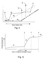
- FIG. 4 depicts a graphical representation of system characteristics.
- FIG. 5 depicts another graphical representation of system characteristics.
- FIG. 6 depicts a cross-sectional view of embodiments of a treatment system.
- FIG. 7 depicts embodiments of a treatment system operating in a low-flow state.
- FIG. 8 a depicts a cross-sectional view of embodiments of system operating a treatment state.
- FIG. 8 b depicts a cross-sectional view of embodiments of an over-flow diverter operating in an over-flow state.
- FIG. 9 a depicts a perspective-view of embodiments of an over-flow diverter operating in a high-flow state.
- FIG. 9 b depicts a perspective-view of embodiments of an over-flow diverter operating in an over-flow state.
- FIGS. 10 a and 10 b depict a cross-sectional view of embodiments of an over-flow diverter operating in an over-flow state.
- FIGS. 11 a and 11 b depict a plan-view of a diverter.
- FIGS. 12 a through 12 c depict a plan-view of a system.
- FIGS. 13 a through 13 c depict a plan-view of a support system.
- FIGS. 14 a and 14 b depict a cross-sectional view of use of a retainer support.
- the invention provides systems, devices, and methods for using the same for treating flowing water, for example removing some or all of pollutants carried in storm water runoff.
- the invention provides for a treatment system comprising a cartridge chamber having an inlet and an outlet, and one or more cartridges housed therein.
- the cartridges contain media that is suitable for removing one or more pollutants from storm water when contacted with the media.
- the treatment system further includes devices that work in concert to regulate the flow of liquid through the cartridge chamber so that the cartridges operate within selected flow rates to optimize pollutant removal efficiency, including, but not limited to, valves for regulating the flow of liquid through the cartridges, and diverters for diverting excess liquid flow to prevent release of retained pollutants from the cartridge chamber in the event of over-flow events.
- FIG. 1 depicts a perspective-view of a system according to embodiments of the invention.
- Liquid treatment system 100 comprises cartridge chamber 110 , which houses cartridges 120 attached to manifold 130 . Beneath the perspective-view is an idealized side-view showing the three general regions of the cartridge chamber, an overflow control region 333 , a treatment region 313 , and a flow control region 334 .
- Cartridge chamber 110 is further divided into flow control region, treatment region that comprises a sedimentation zone and a treatment zone, and a valve region, wherein a valve to regulate flow through the system is housed.
- liquid flows into cartridge chamber 110 through an inlet, not shown. The liquid then flows towards and through cartridges 120 and on through manifold 130 , which leads to an outlet, not shown.
- treatment region 313 is further divided into a treatment zone 502 , wherein liquid enters into cartridges 120 when the liquid is present in treatment zone 502 , and sedimentation zone 503 , wherein sediments suspended in inflowing liquid can settle and accumulate below cartridges 120 , when supported above the floor of the cartridge chamber.
- FIG. 2 a shows a cartridge 120 having cartridge outer wall 140 and cartridge inner wall 150 , having disposed therebetween, media region 154 having therein and media 155 , and wherein inner wall 150 further defines cartridge lumen 153 that is in communication with cartridge outlet 170 .
- Cartridge outlet 170 attaches to either directly to manifold 130 or indirectly through coupling 180 .
- the coupling 180 may attach to either manifold 130 , cartridge outlet 170 , or both, and may be attached using a threaded coupling, or non-threaded coupling, which may include one or more hose-type clamps, a slip fit fitting, a bayonet-type fitting, compression fitting.
- coupling 180 has a length long enough to permit elevation of cartridge 120 above the floor of the cartridge chamber so as to prevent accumulation of sediment against some or all of outer wall 140 by creating a sedimentation area disposed between the floor of the cartridge chamber and cartridge 120 .
- cartridge 120 may be disassembled to permit cleaning of the inner and outer cartridge walls and to permit exchange or reconditioning of media 155 .
- Retainer boss or recess 613 provides for a point of attachment or contact for a retainer bar to restrict movement of cartridge 120 during operation. Retainer boss 613 may be placed on the portion of cartridge 120 opposite cartridge outlet 170 .
- a coupling separator tool may be used to separate the coupling from the manifold, thus liberating cartridge 120 .
- a coupling separator tool may be a lever handle terminating in a bifurcation, wherein the distance between each prong is greater than that of the width or diameter of the coupling, so as to permit the bifurcation to slide past the coupling so that the lever handle may be articulated to cause a separating force to be applied between the coupling and either the manifold or the cartridge outlet, or both, resulting in the separation of the cartridge from the manifold.
- Cartridge 120 may be fabricated from a variety of materials.
- the outer and inner cartridge wall may be made from a permeable material, such as a porous material or a screen, plastic, polymer(s), and/or metal (e.g., aluminum, steel, stainless steel, etc.).
- Outer and inner walls 140 and 150 may be specially treated to minimize accumulation of material onto their surfaces.
- outer wall 140 may be coated with a non-sticking material such as PTFE or Teflon, to prevent the sticking of sediments to the surface of outer wall 140 .
- a pre-filter sleeve may be placed against outer wall 140 to provide additional treatment capacity to cartridge 120 .
- Pre-filter sleeves may be made from foam (e.g., elastomeric foam) woven fabric, (e.g., fiberglass or a polymer).
- foam e.g., elastomeric foam
- pre-filters would be exchanged at in between cartridge exchanges to effectively prolong the life of the cartridge. This is especially useful in applications where fine suspended solids are found which do not readily sediment, yet are large enough to plug the interstitial spaces within the bed formed by the media. In this situation, the pre-filter would serve to trap such fine solids from the liquid prior to the liquid contacting the media in the bed.
- Pre-filters may also provide a treatment to the fluid different than the treatment provided by the media, thus creating a combination of treatments.
- media may be mixed media, wherein different media components are layered and/or mixed together within the media region of cartridge 120 .
- Cartridges may further comprise ends 141 which server to space-apart outer and inner cartridge walls 140 and 150 , and to close off the ends of the media space.
- Ends 141 may be made from wood, metal, plastic or a polymer, among other material compatible with the liquid to be treated.
- Ends 141 may further include one or more recesses for receiving the outer and/or inner cartridge wall edges, to retain and protect the edge of such walls from catching or snagging during movement or exchange of cartridges 120 .
- Cartridge 120 may further include outer shroud that, in some embodiments, further protects cartridge outer wall 140 from plugging by providing a longer fluid path for which fluid containing fine solids must travel. This longer path serves to reduce the turbulence of the fluid as it enters cartridge 120 .
- the outer shroud may further provide for other benefits as described in U.S. Pat. No. 6,027,639, by Lenhart, et al., and U.S. Pat. No. 5,707,527, by Knutson, et al., both of which are herein incorporated by reference for all purposes, and the specific purposes disclosed therein and herein.
- FIG. 2 b depicts a linear array of cartridges 120 that are attached to manifold 130 via coupling 180 .
- the plurality of cartridges 120 are held in position by retainer 600 .
- FIG. 2 c illustrates how coupling 180 (joining cartridge 120 to manifold 130 ) may be elongate.
- FIG. 2 d illustrates how the coupling 180 may be flexible between cartridge 120 and manifold 130 .
- Some embodiments use a flexible hose that is press-fit or slip fitted into the cartridge outlet, to provide for ease of removal of cartridge 120 during servicing or exchange.
- FIG. 3 depicts a plan-view (i.e., bird's eye view) of the cartridge chamber 110 having therein a plurality of cartridges 120 . Also shown is diverter 310 , and valve housing 245 that houses a valve. Both the diverter and valve housing are further described below.
- Embodiments of the system may include the use of a flow valve and diverter to control the level (e.g., depth) of liquid in the cartridge chamber as well as the flow rate of liquid passing through the chamber.
- Line A of the idealized graph shown in FIG. 4 plots the depth of liquid in a cartridge chamber as a function of the rate liquid is flowing into the chamber system (Line B).
- the graph also shows an overflow rate of liquid discharging from the system (Line C) as a function of the flow rate of liquid entering the system. Additional details about the interrelationships between the liquid depth, liquid inflow rate, and overflow discharge rate shown in FIG. 4 will be given below.
- a valve may be used to regulate the depth of liquid in the cartridge chamber.
- Liquid to be treated flows through the cartridges, into the cartridge lumens, onward through the coupling and manifold towards the valve, wherein the valve controls the flow of liquid through the cartridges so as to substantially maintain the level of liquid collected in the cartridge chamber about a selected level within a range of system inflow rates.
- FIG. 5 provides an idealized graphical depiction of the relationship between the liquid discharge rate from the cartridge system, controlled at least in part by valve actuation, as a function of the liquid depth in the treatment region of the cartridge chamber.
- Region “(v)” of FIG. 5 is a region where the depth of liquid in the treatment region is low enough that the valve remains substantially closed.
- liquid may accumulate in the cartridge chamber until the liquid level rises to a certain point (i.e., point “E”).
- point “E” the valve may begin to open (“actuation”), to increase the flow of liquid from the treatment region through the cartridges and onward to the outlet.
- the valve opening may increase with rising liquid level throughout region “(w)”, until the valve is fully open at point “F”.
- point “F” the liquid discharge rate through the open valve may increase slightly with increasing depth as shown by region “(x)”.
- point “G” overflow liquid may discharge from the system, further increasing the discharge rate in region “(y)”.
- FIG. 6 depicts an embodiment of a cartridge system in operation, shown in cross-sectional view.
- cartridge system 100 comprises cartridge chamber 110 having chamber inlet 210 and chamber outlet 220 .
- cartridge 120 Inside cartridge chamber 110 is cartridge 120 , which is in communication with valve 230 through coupling 180 and manifold 130 , wherein valve 230 is actuated by changes in fluid level 200 of treatment region 313 shown in FIG. 1 .
- Valve 230 is actuated by valve shaft 240 , which is connected to valve arm 250 , as valve arm 250 changes position, as shown by the double arrow, in relation to changes in fluid level 200 that causes movement of float 261 which acts on valve arm 250 through float connecting shaft 280 .
- valve shaft 240 which is connected to valve arm 250 , as valve arm 250 changes position, as shown by the double arrow, in relation to changes in fluid level 200 that causes movement of float 261 which acts on valve arm 250 through float connecting shaft 280 .
- valve arm 250 moves up to open valve 230 , thus permitting increased amounts of liquid to flow through valve 230 , which causes increased flow through media 155 , thereby removing some or all material in a fluid flowed through the cartridge system.
- FIG. 7 depicts valve 230 in a closed state in response to liquid level 200 being below the point of actuation for valve 230 .
- a residual amount of fluid remains in treatment region 313 in FIG. 1 , so as to keep sedimentation zone 503 hydrated to minimize the caking of sediments.
- a drain port permits the draining of treatment zone 502 liquid from the cartridge chamber so that the liquid level inside the treatment region 313 is maintained slightly above the sedimentation zone 503 .
- FIG. 8 a depicts an embodiment wherein diverter 310 further comprises treatment conduit 211 for introducing liquid into treatment region 313 in FIG. 1 within or about sedimentation zone 503 , through diffuser 212 , which directs effluent from treatment conduit 211 in a direction substantially parallel to the chamber floor, to reduce sediment stirring during operation.
- diffuser 212 is a “tee” having an inlet and two or more outlets.
- the system depicted in FIG. 8 a operates in the following manner. After liquid enters the system through chamber inlet 210 , it passes through diverter 310 , wherein the liquid in a first non-overflow state flows into diverter 310 , and is entirely routed into treatment conduit 211 , which terminates inside of treatment region 313 in or about sedimentation zone 503 . As the liquid level rises from sedimentation zone 313 into treatment zone 502 , the float 261 begins to move upward thus actuating valve 230 . Upon actuation, valve 230 opens and liquid will begin to flow through cartridge 120 , onward through manifold 130 and through valve 230 , ultimately exiting the system through outlet 220 . By routing liquid directly into the sedimentation zone, suspended sediments may settle onto the floor of the chamber more quickly than if the liquid were entered into the top of the treatment region 313 , thereby further limiting the potential for clogging of the outer wall and media of cartridge 120 .
- a valve may be used to control the flow of liquid from the cartridge lumen in relation to the level of liquid inside cartridge lumen 130 .
- An example of this type of valve arrangement is described in U.S. Pat. No. 6,027,639, by Lenhart, et al., and U.S. Pat. No. 5,707,527, by Knutson, et al., both of which are herein incorporated by reference for all purposes, and the specific purposes disclosed therein and herein.
- the valve system of Lenhart or Knutson may be combined with the valve system of the present invention to further control the level of liquid both inside and outside of the cartridge.
- FIG. 8 b depicts the system operating in an over-flow state wherein the liquid flow rate is great enough to cause a portion of the liquid to flow over diverter weir 320 and on through by-pass conduit 300 .
- Both the by-pass routed portion of the liquid and the portion that flowed through the cartridges, “treated” liquid reunite, in some embodiments, in valve housing 245 , prior to flowing outside of the system through chamber outlet 220 .
- treated and by-pass portions of the liquid may be handled independently outside of the cartridge system.
- valve 230 is not actuated until liquid level 200 is above the top region of cartridge 120 so that substantially all of outer cartridge wall 150 is submerged under liquid before valve 230 is actuated to increase the flow of fluid from cartridge lumen 153 through conduit 230 , and ultimately through outlet 210 .
- a low flow outlet permits fluid to pass through the cartridge system when the flow rate is low, wherein the fluid passes through cartridge 120 .
- the low flow outlet is achieved by incomplete closure of valve 230 , or by liquid path between treatment region 313 and chamber outlet 220 .
- Another aspect of the invention provides, in certain embodiments, for a diverter for diverting over-flow liquid to a by-pass conduit so as to further regulate the liquid level within the cartridge chamber treatment area.
- a diverter may be external and upstream to the cartridge chamber, or may be located inside of the cartridge chamber. Locating the diverter inside of the cartridge chamber can reduce the cost of construction because only one hole needs to be dug, for in-ground installations, and because all components can be included in a pre-fabricated “one-piece” structure, or in pieces that may be assembled at the system's installation site.
- a diverter acts mainly to prevent flow through the treatment region 313 in excess of the flow that can be passed through the cartridges to prevent overflowing of the treatment region 313 and scouring or scavenging of the settled sediments captured in the treatment region 313 from carrying such sediments further downstream of the system.
- the liquid that is to be treated can be treated in a manner which optimizes cartridge capacity, including, maintaining flow through the cartridge in a flow rate range consistent with the optimal flow rate range for the particular cartridge and the media contained therein, as well as optimizing the sedimentation conditions within the treatment region 313 shown in FIG. 1 .
- FIG. 4 depicts a graphical illustration representing characteristics of embodiments of a system where the diverter and the flow valve work together to manage liquid flow through the cartridge chamber.
- Line A represents the relative depth of liquid in the treatment region 313
- line B represents the rate of flow of liquid entering the system
- line C represents the flow rate of over-flow liquid discharging from the system.
- the control valve is substantially shut to cause inflowing liquid to accumulate in the treatment region 313 as shown by line A, which shows that the depth of water rapidly rises, due to accumulation, then plateaus as the liquid level achieves a desired depth and the valve opens to increase flow of liquid through the cartridges.
- liquid by-pass begins at point (q), where regulation of water flowing into the treatment region 313 begins to be limited by the diverter, as inflowing liquid begins to spill over an over-flow weir that is in communication with a by-pass conduit which transfers liquid from the inlet side of the system, to the outlet side of the system, and may be joined with post-treatment effluent flowing from the cartridges.
- a by-pass conduit which transfers liquid from the inlet side of the system, to the outlet side of the system, and may be joined with post-treatment effluent flowing from the cartridges.
- FIG. 9 a depicts an exemplary diverter 310 in communication with inlet 210 having liquid flow 50 flowing therethrough.
- liquid flow 50 flows into diverter 310 , it splits into two flow routes 333 , routing about over-flow weir walls 315 , which are spaced-apart from diverter walls 312 at a distance such that when liquid flow 50 exceeds a certain flow rate, a portion of liquid flow 50 , over flow 330 , spills over weir wall 320 and flows down through overflow conduits 300 , then outside of the cartridge chamber 110 .
- the non-diverted portion of liquid flow 50 , treatment flow 335 flows out from diverter outlets 337 into treatment region 313 , where it then flows through the cartridges, manifold, valve and chamber outlet.
- FIG. 9 b depicts an alternative embodiment, wherein flow routes 330 include routing the liquid into treatment conduits 339 , and optionally through a diverter tee 314 into a split flow path 370 , which flows outward for distance in a direction substantially parallel to the floor of the cartridge chamber.
- FIGS. 10 a and 10 b depict a cross-sectional view of diverter 310 .
- the flow of liquid, shown as an arrow, through diverter 310 is at a rate that is below over flow.
- FIG. 10 b depicts in cross-section how a portion of the liquid flow, shown as a bifurcated arrow, flows over diverter weir 320 and downward through over-flow conduit 300 .
- FIG. 11 a depicts a plan-view of an exemplary embodiment of a diverter.
- Inlet 210 routes liquid flow 50 into diverter 310 , wherein two flow paths 61 are established and flow towards treatment region 313 .
- FIG. 11 b depicts the same plan-view of FIG. 11 a , but shows the effect of an increased liquid flow 50 causing a portion of that liquid to spill over diverter weir 320 , and flow onward through over-flow conduits 300 thereby causing a portion of liquid flow 50 to by-pass treatment region 313 .
- FIGS. 12 a through 12 c depict a plan-view flow scheme at different flow stages for embodiments according to the invention.
- FIG. 12 a depicts the flow scheme through cartridge chamber 110 of the system when during the accumulation stage.
- Valve 230 is shut in response to a low liquid level in the treatment region 313 , preventing flow of treated liquid flow 500 from manifold 130 from exiting cartridge chamber 110 and causing liquid to accumulate in treatment region 313 .
- the cartridges and support racks have been removed for clarity. Since FIG. 12 a is in sub-overflow state, substantially no fluid is present in the bypass conduit 300 or in chamber outlet 220 .
- FIG. 12 b depicts the flow route of the system when it is in treatment stage, wherein treated liquid flow 500 flows through now open valve 230 to pass through valve housing 245 and outlet 220 as effluent 501 .
- the flow rate of effluent 501 varies in accordance to the system inflow rate so as to maintain the liquid level in the treatment region 313 about a selected level (e.g., above the cartridges). Accordingly, during relatively low inflow events, effluent 501 will likewise be relatively low, even though the liquid level within the treatment region 313 is maintained about a selected level, (e.g., above the cartridges).
- FIG. 12 c depicts the flow route of the system when it is in treatment/overflow stage.
- treated liquid flow 500 continues to flow through valve 230 , housing 245 , and outlet 220 to become effluent 501 .
- diverter 310 has gone into overflow state and a portion of the inflowing liquid is flowing over diverter weir 320 and flowing through by-pass conduit 300 as non-treated liquid overflow 520 , which may be blended with treated liquid flow 500 to form a composite effluent 501 containing treated and non-treated liquid.
- treated liquid flow 500 and non-treated liquid overflow 520 are routed to different receiving bodies.
- the treated liquid flow is routed to a storage reservoir for irrigation, whereas the untreated liquid flow is routed to a natural receiving body.
- a diverter is situated outside of the cartridge chamber, wherein the diverter routes over-flow around the cartridge chamber.
- a secondary by-pass conduit may be located inside of the cartridge chamber to increase by-pass flow capacity beyond the flow capacity of the primary by-pass conduit and prevent scouring of the treatment region 313 when the excess capacity is routed through the treatment region 313 because system inflow exceeds over-flow and/or cartridge processing capacity.
- the cartridges are elevated above the floor of the cartridge chamber upon supports (e.g., moveable supports) that can be moved about during the operation and/or care of the system, such as the non-limiting example of cleaning, wherein the supports can be moved away from the floor to facilitate removal of the accumulated sediments.
- supports e.g., moveable supports
- cartridges are retained by overhead retainers that support and maintain the location of each cartridge about a fixed position.
- the cartridges are supported by a combination of support between the floor of the cartridge chamber and the cartridge and an overhead retainer.
- FIGS. 13 a through 13 c Embodiments of a system that includes supports are depicted in FIGS. 13 a through 13 c .
- FIG. 13 a depicts cartridge chamber 110 having a plurality of cartridges 120 distributed about therein, wherein the cartridges rest upon one or more supports 260 , (e.g., rack support).
- support 260 laterally positions cartridges 120 as well as elevates cartridges 120 above the floor of the cartridge chamber.
- lateral support is achieved by a two rail support wherein the cartridge outlet or coupling is flanked by each rail support so as to prevent cartridges from skidding off the support in a direction about normal to the run of such rails. Rungs may further be added to prevent cartridge skidding along about the run of such rails.
- cartridges can be skidded along the run of the rails of the track, but not to the side of the tracks. A track crossing may be included to provide for selected lateral skidding of the cartridges among two or more tracks to permit “track switching”.
- the supports may be made from materials compatible with the liquid to be treated, including, but not limited to stainless steel, aluminum, brass, plastic, polymers, or any combination of these materials.
- Tracks may further include skid inlays to provide a bearing surface for track skidding to reduce the effort needed to move cartridges about the cartridge chamber upon the supports.
- the supports further include legs, such as collapsible legs that collapse or are otherwise movable when the support is moved about or articulated.
- Retainers which may include a retainer bar, may retain a plurality of cartridges in a row of an array of cartridges. In some embodiments where several rows of cartridges are employed, several retaining bars may be used to retain each row. Several rows are also retainable by a transverse retainer bar that retains each of the retainer bars with respect to each other. Retainer bars may be separable from the cartridges and from other transverse retainer bar. Retaining bars, and in particular, transverse retaining bars, may be attached or attachable to the cartridge chamber, (e.g., to one or more walls of the cartridge chamber) or to a support, if used. Embodiments may also provide for the attachment of retainer bars and/or transverse retainer bars by combinations of bar receiving pockets and retention pins on opposite walls of the cartridge chamber.
- FIG. 13 b depicts the same embodiment of FIG. 13 a , however, cartridges 120 have been removed, as would be the case during cartridge exchange or floor cleaning procedures.
- Supports 260 further comprise transverse sub-supports arms 266 that are movably attached to the walls of the cartridge chamber at attachment points 265 (e.g., hinges).
- FIG. 13 c depicts the movement of supports 260 away from cartridge chamber floor 111 , thus reducing the obstructions present in adjacent the floor area so that accumulated sediments can be removed from the cartridge chamber.
- Couplings 180 as shown in for example in FIG. 12 a are not shown in FIGS. 13 a through 13 c for clarity.
- FIG. 14 a shows an intact system where inside of cartridge chamber 110 is housed a plurality of cartridges 120 supported above floor 111 by supports 260 .
- Supports 260 are elevated above floor 111 by legs 263 and wall mount 265 (e.g., a hinged mount).
- Supports 260 further comprise rails 264 that flank the outlet/coupling of cartridge 120 to laterally stabilize cartridges 120 .
- Cartridges 120 are further retained in position by retainer 600 , which may comprise retainer bars 615 , wherein the retainer bars 615 may run substantially parallel to rails 264 .
- Retainer bars may be directly attached to cartridge chamber walls, or indirectly attached through transverse retainer bars, or through a combination of both.
- Cartridges 120 may contact retainer bars 615 through at a retainer contact point (e.g., retainer boss 613 ).
- Retainer bars 615 may be further spatially isolated by transverse retainer bars 601 that attach to retainer bars 615 and cartridge chamber 110 , such as a wall of cartridge chamber 110 , and may be attached through a detachable fastener, for example, but not limited to, pocket receiver 620 and pin retainer/receiver 610 .
- a system may include at least one transverse retainer bar, situated adjacent opposing ends of cartridge chamber 110 , running substantially perpendicular to retainer bars 615 .
- the invention also includes methods for using the system and devices disclosed herein.
- removal of cartridges 120 from cartridge chamber 110 may be performed as follows. First, retainer pins 610 are removed from their receiver to liberate transverse retainer bar 601 . Then, retainer bars 615 are lifted away from retainer bosses 613 . With retainer 600 removed, cartridges 120 may be moved about, for example, tilted to reveal access to coupling 180 for detaching coupling 180 from cartridge 120 . With coupling 180 now separated from cartridge 120 , cartridge 120 may be further moved about, and removed from cartridge chamber 110 through, for example, an access hole located in the top wall of cartridge chamber 110 , and, for example, using a hoist located outside of cartridge chamber 110 .
- supports 260 may then be moved away from floor 111 by lifting the side of the support distal wall mount/hinge 265 , to swing out of the way support 260 .
- a latch retains support 260 against the wall during service.
- Couplings 180 may remain adjacent floor 111 , partially immobilized by surrounding accumulated sediment, if present to sufficient levels. Couplings 180 may then be moved away from floor 111 and temporarily attached to the wall to further expose floor 111 for cleaning.
- manifold 130 may be removed from cartridge chamber 110 during cleaning and maintenance, and later reinstalled and attached by straps afterwards, thus further exposing floor 111 and allowing for servicing and repair of manifold 130 and couplings 180 outside of cartridge chamber 130 .
- couplings 180 may be fixedly connected to support 260 , so that when support 260 is moved away from floor 111 , couplings 180 may be moved and held away from floor 111 .
- Another aspect of the invention provides for error or status reporting devices that change state upon the occurrence of an event.
- a lever having a float attached thereto may move and latch in an upward state upon the liquid level inside the cartridge chamber exceeding a certain point, thus indicating that a treatment region 313 overflow state was realized in the past, suggesting that either the system is undersized for treating inflow during peak events and/or that the cartridges may need to be serviced.
- a comparator for comparing flow rates between different flow routes within the system such as comparing the flow rates between liquid that flows through cartridges 120 and liquid that flows through the overflow conduit 300 .
- Still another example provides for a cartridge lumen liquid level indicator for comparing the liquid level inside the lumen of the cartridge with the liquid level outside of the lumen of the cartridge, the differential therein suggesting the amount of head loss between the outside and inside of the cartridge which may be correlative to the degree of plugging that the cartridge or its media is experiencing.
- an indicator rod having first and second ends, wherein a first end would pass through the upper end of the cartridge, and the second end would reside in the lumen of the cartridge and has a float attached thereto.
- the float would also act to regulate liquid flow through the cartridge, and in others, the float would not act to regulate liquid flow through the cartridge when actuated. Changes in length of the first end of the indicator rod protruding above the cartridge would correlate to the liquid level inside the cartridge.
- Cartridges may further include a vent for purging air from inside the cartridge lumen, a check valve for purging air and/or creating a vacuum inside the cartridge lumen. Cartridges may further be open to ambient air via a breather tube that extends above the liquid level inside of the cartridge chamber.
- Some embodiments of the invention may further include a sump well or wells located inside the cartridge chamber to further increase the accumulated sediment capacity of the system and to simplify removal of the sediment.
- the system may further include a treatment which included bioremediation, the use of additives such as coagulants and/or flocculants by, for example, self-feeding.
- a treatment which included bioremediation, the use of additives such as coagulants and/or flocculants by, for example, self-feeding.
- an anti-scouring measure is provided to further prevent scouring of the treatment region 313 during peak flow events.
- an upstream over-overflow diversion device comprising an upstream valve that shuts off diverter flow to the treatment region 313 when the liquid level in the treatment region 313 exceeds a certain point, for example, a level higher than needed to fully actuate the downstream valve, such as valve 230 .
- Another aspect of the invention provides for a diverter output regulator which regulates the liquid output of the diverter which flows into the treatment region in relation to the flow rate of the liquid being routed through the over-flow route of the cartridge system.
- a diverter output regulator which regulates the liquid output of the diverter which flows into the treatment region in relation to the flow rate of the liquid being routed through the over-flow route of the cartridge system.
- gate valve(s) may be actuated in relation to changes in the rate of flow of liquid flowing in the overflow route of the system.
Abstract
Description
Claims (26)
Priority Applications (1)
| Application Number | Priority Date | Filing Date | Title |
|---|---|---|---|
| US10/901,905 US6998038B2 (en) | 2003-07-28 | 2004-07-28 | Stormwater treatment system |
Applications Claiming Priority (2)
| Application Number | Priority Date | Filing Date | Title |
|---|---|---|---|
| US49074203P | 2003-07-28 | 2003-07-28 | |
| US10/901,905 US6998038B2 (en) | 2003-07-28 | 2004-07-28 | Stormwater treatment system |
Publications (2)
| Publication Number | Publication Date |
|---|---|
| US20050040113A1 US20050040113A1 (en) | 2005-02-24 |
| US6998038B2 true US6998038B2 (en) | 2006-02-14 |
Family
ID=34115430
Family Applications (1)
| Application Number | Title | Priority Date | Filing Date |
|---|---|---|---|
| US10/901,905 Expired - Fee Related US6998038B2 (en) | 2003-07-28 | 2004-07-28 | Stormwater treatment system |
Country Status (4)
| Country | Link |
|---|---|
| US (1) | US6998038B2 (en) |
| AU (2) | AU2004261653B2 (en) |
| CA (1) | CA2533765A1 (en) |
| WO (1) | WO2005012183A2 (en) |
Cited By (27)
| Publication number | Priority date | Publication date | Assignee | Title |
|---|---|---|---|---|
| US20050051499A1 (en) * | 2003-09-04 | 2005-03-10 | Nino Khalil Ibrahim | Large area catch basin filter |
| US20060016767A1 (en) * | 2004-07-23 | 2006-01-26 | I.S.C. Environmental, Inc. | Fluid filter system and related method |
| US20070056889A1 (en) * | 2005-09-09 | 2007-03-15 | Cds Technologies, Inc. | Apparatus for separating solids from flowing liquids |
| KR100752792B1 (en) | 2006-04-17 | 2007-08-29 | (주)대성그린테크 | Ds-hf-rr |
| US20080277326A1 (en) * | 2007-05-09 | 2008-11-13 | Contech Stormwater Solutions, Inc. | Pre-Assembled Flow Control Structure and Related Media Filtration System |
| US20090045128A1 (en) * | 2007-08-15 | 2009-02-19 | Christopher Adam Murray | Filter For Removing Sediment From Water |
| US20090314723A1 (en) * | 2008-06-19 | 2009-12-24 | Jacob David W | Flow control structure and related media filtration system |
| US20110049024A1 (en) * | 2009-08-31 | 2011-03-03 | Thomas Pank | Method for treating runoff water using a series of treatment sequences to remove fine pollutants and clay |
| US20120031854A1 (en) * | 2009-04-08 | 2012-02-09 | Kristar Enterprises, Inc. | Modular Storm Water Filtration System |
| US20120132581A1 (en) * | 2007-08-15 | 2012-05-31 | Monteco Ltd. | Filter for removing sediment from water |
| US8221618B2 (en) * | 2007-08-15 | 2012-07-17 | Monteco Ltd. | Filter for removing sediment from water |
| US8535533B2 (en) | 2009-12-22 | 2013-09-17 | Kristar Enterprises, Inc. | Bioretention system with high internal high flow bypass |
| US8721885B2 (en) | 2010-08-30 | 2014-05-13 | Aleksandra Drizo | System for removing phosphorus from wastewater |
| US8911626B2 (en) | 2009-12-22 | 2014-12-16 | Oldcastle Precast, Inc. | Bioretention system with internal high flow bypass |
| US20150183659A1 (en) * | 2013-12-31 | 2015-07-02 | Zachariha Kent | Partitioned water treatment systems with vertical filtration units |
| US9469981B2 (en) | 2009-12-22 | 2016-10-18 | Oldcastle Precast, Inc. | Fixture cells for bioretention systems |
| US9506233B2 (en) | 2013-06-14 | 2016-11-29 | Oldcastle Precast, Inc. | Stormwater treatment system with gutter pan flow diverter |
| US9512606B2 (en) | 2011-08-21 | 2016-12-06 | Oldcastle Precast, Inc. | Bioretention swale overflow filter |
| US9561489B2 (en) | 2013-03-15 | 2017-02-07 | American Peat Technology, Llc | Particulate sorption medium prepared from partially decomposed organic matter |
| US9649620B2 (en) | 2013-03-15 | 2017-05-16 | American Peat Technology, Llc | Particulate sorption medium prepared from partially decomposed organic matter |
| US10118846B2 (en) | 2014-12-19 | 2018-11-06 | Oldcastle Precast, Inc. | Tree box filter with hydromodification panels |
| US10563392B2 (en) | 2015-08-11 | 2020-02-18 | Mmt, Inc. | Stormwater biofiltration system and method |
| US10676910B2 (en) * | 2013-07-25 | 2020-06-09 | Abt, Inc. | Drainage device and methods for constructing and use |
| US10722878B1 (en) | 2017-06-01 | 2020-07-28 | American Peat Technology, Llc | Weak ion exchange particulate medium prepared from phenol-containing organic matter for anions contained in aqueous solutions |
| US20220023778A1 (en) * | 2020-07-27 | 2022-01-27 | Pre-Con Products | Double-Filter Basket for StormWater Retention System Drain |
| US11420880B2 (en) | 2017-10-18 | 2022-08-23 | Oldcastle Infrastructure, Inc. | Stormwater filtration system with internal bypass pipe |
| US11479487B2 (en) | 2017-10-17 | 2022-10-25 | Oldcastle Infrastructure, Inc. | Stormwater management system with internal bypass |
Families Citing this family (4)
| Publication number | Priority date | Publication date | Assignee | Title |
|---|---|---|---|---|
| US7485218B2 (en) * | 2005-03-21 | 2009-02-03 | Ecosense International, Inc. | Storm water filtration system |
| WO2007124297A1 (en) * | 2006-04-21 | 2007-11-01 | Contech Stormwater Solutions Inc. | Stormwater treatment system with automated contaminant buildup detection |
| US8110099B2 (en) * | 2007-05-09 | 2012-02-07 | Contech Stormwater Solutions Inc. | Stormwater filter assembly |
| NZ603933A (en) * | 2009-01-13 | 2014-03-28 | Access Business Group Int Llc | Gravity feed water treatment system |
Citations (27)
| Publication number | Priority date | Publication date | Assignee | Title |
|---|---|---|---|---|
| US556725A (en) | 1896-03-17 | Water-filter | ||
| US887069A (en) | 1908-01-30 | 1908-05-12 | John A Cotter | Filter. |
| US1371110A (en) | 1919-10-21 | 1921-03-08 | U G Pelphrey | Inlet-valve casing |
| US2609932A (en) | 1948-10-05 | 1952-09-09 | Bendix Aviat Corp | Fluid purifying device |
| US3027910A (en) * | 1956-09-10 | 1962-04-03 | Burton L Oliver | Flow control apparatus |
| US3314546A (en) | 1964-06-02 | 1967-04-18 | Stone Filter Co Inc | Cartridge filter |
| US4427542A (en) | 1983-01-05 | 1984-01-24 | Glover Richard E | Inline fuel filter device |
| US4643836A (en) | 1985-10-01 | 1987-02-17 | Schmid Lawrence A | Radial flow filter having air fluidizing backwash means |
| US4997561A (en) * | 1988-10-13 | 1991-03-05 | Faudi Feinbau Gmbh | Filtering apparatus comprising parallel cylindrical filter elements disposed in a housing chamber |
| US5133619A (en) | 1991-03-18 | 1992-07-28 | Murfae George W | Storm water filtration system for use with conventional storm water collection sewers |
| US5316589A (en) | 1992-06-24 | 1994-05-31 | Krieger Jr Frederick W | Method for controlling street surface pollutants |
| US5322629A (en) | 1993-03-02 | 1994-06-21 | W & H Pacific Inc. | Method and apparatus for treating storm water |
| US5330651A (en) | 1991-05-10 | 1994-07-19 | University Of Waterloo | Treatment of contaminated agricultural run-off |
| US5458769A (en) | 1990-01-24 | 1995-10-17 | Johannessen; Jorgen M. | Floor drain |
| US5573349A (en) | 1994-10-20 | 1996-11-12 | Paoluccio; John A. | Sediment dike with absorber apparatus |
| US5624576A (en) | 1995-05-30 | 1997-04-29 | Csf Treatment Systems, Inc. | Pelletized composition for treatment of storm water runoff |
| US5624552A (en) | 1993-02-22 | 1997-04-29 | University Of Waterloo | In-ground water treatment system |
| US5632889A (en) | 1995-06-09 | 1997-05-27 | Tharp; Gary D. | Filter cartridge for separating liquid hydrocarbons from water |
| US5707527A (en) | 1996-04-30 | 1998-01-13 | Stormwater Treatment Llc | Apparatus and method for treating storm water runoff |
| US5770080A (en) | 1997-04-23 | 1998-06-23 | Malone; Ronald F. | Air charged backwashing bioclarifier |
| US5788848A (en) | 1994-06-17 | 1998-08-04 | Cds Tech Ltd | Apparatus and methods for separating solids from flowing liquids or gases |
| US5954952A (en) | 1998-01-30 | 1999-09-21 | Alpine Stormwater Management Company | Stormwater catch basin filter assembly |
| US6027639A (en) * | 1996-04-30 | 2000-02-22 | Stormwater Treatment Llc | Self-cleaning siphon-actuated radial flow filter basket |
| US6059964A (en) | 1998-12-03 | 2000-05-09 | Alpine Stormwater Management Company | Collapsible catch basin grate filter assembly |
| US6517724B1 (en) | 1998-04-16 | 2003-02-11 | Ronald F. Malone | Air charged backwashing bioclarifier |
| US6533941B2 (en) | 2001-08-14 | 2003-03-18 | George R. Butler | Flow through drain filter for a stormwater or wastewater catch basin |
| US20030094407A1 (en) | 2001-11-20 | 2003-05-22 | Stormwater Management, Inc. | Filter cartridge with regulated surface cleaning mechanism |
Family Cites Families (4)
| Publication number | Priority date | Publication date | Assignee | Title |
|---|---|---|---|---|
| US94407A (en) * | 1869-08-31 | Improved sorghum-pan skimmer | ||
| US112807A (en) * | 1871-03-21 | Improvement in mouse and animal-traps | ||
| US5820770A (en) * | 1992-07-21 | 1998-10-13 | Seagate Technology, Inc. | Thin film magnetic head including vias formed in alumina layer and process for making the same |
| US6659048B1 (en) * | 2002-06-06 | 2003-12-09 | Emerson Electric Co. | Supercharged hot water heater |
-
2004
- 2004-07-28 US US10/901,905 patent/US6998038B2/en not_active Expired - Fee Related
- 2004-07-28 CA CA002533765A patent/CA2533765A1/en not_active Abandoned
- 2004-07-28 AU AU2004261653A patent/AU2004261653B2/en not_active Ceased
- 2004-07-28 WO PCT/US2004/024578 patent/WO2005012183A2/en active Application Filing
-
2009
- 2009-11-26 AU AU2009240875A patent/AU2009240875B2/en not_active Ceased
Patent Citations (30)
| Publication number | Priority date | Publication date | Assignee | Title |
|---|---|---|---|---|
| US556725A (en) | 1896-03-17 | Water-filter | ||
| US887069A (en) | 1908-01-30 | 1908-05-12 | John A Cotter | Filter. |
| US1371110A (en) | 1919-10-21 | 1921-03-08 | U G Pelphrey | Inlet-valve casing |
| US2609932A (en) | 1948-10-05 | 1952-09-09 | Bendix Aviat Corp | Fluid purifying device |
| US3027910A (en) * | 1956-09-10 | 1962-04-03 | Burton L Oliver | Flow control apparatus |
| US3314546A (en) | 1964-06-02 | 1967-04-18 | Stone Filter Co Inc | Cartridge filter |
| US4427542A (en) | 1983-01-05 | 1984-01-24 | Glover Richard E | Inline fuel filter device |
| US4643836A (en) | 1985-10-01 | 1987-02-17 | Schmid Lawrence A | Radial flow filter having air fluidizing backwash means |
| US4997561A (en) * | 1988-10-13 | 1991-03-05 | Faudi Feinbau Gmbh | Filtering apparatus comprising parallel cylindrical filter elements disposed in a housing chamber |
| US5458769A (en) | 1990-01-24 | 1995-10-17 | Johannessen; Jorgen M. | Floor drain |
| US5133619A (en) | 1991-03-18 | 1992-07-28 | Murfae George W | Storm water filtration system for use with conventional storm water collection sewers |
| US5330651A (en) | 1991-05-10 | 1994-07-19 | University Of Waterloo | Treatment of contaminated agricultural run-off |
| US5316589A (en) | 1992-06-24 | 1994-05-31 | Krieger Jr Frederick W | Method for controlling street surface pollutants |
| US5624552A (en) | 1993-02-22 | 1997-04-29 | University Of Waterloo | In-ground water treatment system |
| US5322629A (en) | 1993-03-02 | 1994-06-21 | W & H Pacific Inc. | Method and apparatus for treating storm water |
| US5788848A (en) | 1994-06-17 | 1998-08-04 | Cds Tech Ltd | Apparatus and methods for separating solids from flowing liquids or gases |
| US5573349A (en) | 1994-10-20 | 1996-11-12 | Paoluccio; John A. | Sediment dike with absorber apparatus |
| US5624576A (en) | 1995-05-30 | 1997-04-29 | Csf Treatment Systems, Inc. | Pelletized composition for treatment of storm water runoff |
| US5632889A (en) | 1995-06-09 | 1997-05-27 | Tharp; Gary D. | Filter cartridge for separating liquid hydrocarbons from water |
| US5707527A (en) | 1996-04-30 | 1998-01-13 | Stormwater Treatment Llc | Apparatus and method for treating storm water runoff |
| US6027639A (en) * | 1996-04-30 | 2000-02-22 | Stormwater Treatment Llc | Self-cleaning siphon-actuated radial flow filter basket |
| EP0900175B1 (en) | 1996-04-30 | 2002-12-04 | Stormwater Treatment LLC | Apparatus and method for treating storm water runoff |
| US5770080A (en) | 1997-04-23 | 1998-06-23 | Malone; Ronald F. | Air charged backwashing bioclarifier |
| US5954952A (en) | 1998-01-30 | 1999-09-21 | Alpine Stormwater Management Company | Stormwater catch basin filter assembly |
| US6517724B1 (en) | 1998-04-16 | 2003-02-11 | Ronald F. Malone | Air charged backwashing bioclarifier |
| US6059964A (en) | 1998-12-03 | 2000-05-09 | Alpine Stormwater Management Company | Collapsible catch basin grate filter assembly |
| US6533941B2 (en) | 2001-08-14 | 2003-03-18 | George R. Butler | Flow through drain filter for a stormwater or wastewater catch basin |
| US20030094407A1 (en) | 2001-11-20 | 2003-05-22 | Stormwater Management, Inc. | Filter cartridge with regulated surface cleaning mechanism |
| US6649048B2 (en) | 2001-11-20 | 2003-11-18 | Stormwater Management | Filter cartridge with regulated surface cleaning mechanism |
| US20040112807A1 (en) | 2001-11-20 | 2004-06-17 | Aberle Daniel W. | Filter cartridge with check valve protection |
Non-Patent Citations (36)
| Title |
|---|
| Absorbent W marketing material: Pillows and socks, on or before 2004, 2 pages. |
| Aqua Treatment Systems, Inc. brochure entitled: "Small-Scale Water Treatment Systems", 1996, 14 pages. |
| Aqua Treatment Systems, Inc. brochure entitled: "So, who gets the last fish?", 1995, 14 pages. |
| Aqua Treatment Systems, Inc. document entitled: "90 Gallon Filter/Oil-Water Separator", 1998, 1 page. |
| Aqua Treatment Systems, Inc. document entitled: "Floor Mounted Catch Basin Insert with False Bottom", 2001, 1 page. |
| Aqua Treatment Systems, Inc. document entitled: "Gullywasher Brand-Filter Baffle Frame and Cartridges", 2002, 1 page. |
| Aqua Treatment Systems, Inc. document entitled: "Gullywasher Brand-Parallel Stormwater Filter Baffle", 2002, 3 pages. |
| Aqua Treatment Systems, Inc. document entitled: "Gullywasher Brand-Radial Flow Filter Cartridge", 2000, 1 page. |
| Aqua Treatment Systems, Inc. document entitled: "Gullywasher Brand-Radial Flow Stormwater Filter", 2000, 12 pages. |
| Aqua Treatment Systems, Inc. document entitled: "Gullywasher Brand-Series Stormwater Filter Baffle", 2002, 2 pages. |
| Aqua Treatment Systems, Inc. document entitled: "Gullywasher Tee Section Filters", Apr. 1999, 1 page. |
| Aqua Treatment Systems, Inc. document entitled: "Gullywasher", 1998, 9 pages. |
| Aqua Treatment Systems, Inc. document entitled: "Radial Flow Perlite Stormwater Filter", 1999, 2 pages. |
| Aqua Treatment Systems, Inc. document entitled: "Sediment Trap/Oil-Water Separator Trench Drain Conversion", 1999, 1 page. |
| Aqua Treatment Systems, Inc. document entitled: "Spill Mate Small Scale Oil-Water Separator", 1998, 1 page. |
| Aqua Treatment Systems, Inc. document entitled: "Stainless Steel Sediment Box", 2001, 1 page. |
| Aqua Treatment Systems, Inc. document entitled: "Trench Drain Filter Baskets", 1999, 1 page. |
| Aqua Treatment Systems, Inc. document entitled: "We have spill kits!", 1998, 1 page. |
| Aqua Treatment Systems, Inc. document entitled: "Wire Gutter for Curb Inlets", 2001, 1 page. |
| Brueske, Christopher et al. "Technology Review: Ultra-Urban Stormwater Treatment Technologies", Sep. 1, 2000, pp. 1-54. |
| CDS Technologies, Inc. document entitled: "Complete line of structural storm water BMPs", Trade Show materials from , on or before 2004, 8 pages. |
| CDS Technologies, Inc. marketing material entitled: "You asked for a compact solution . . . and we've delivered it", on or before 2004, 1 page. |
| Coffey, Laura "Portland firm turns over a new leaf" Daily Journal of Commerce, Seattle, Washington, Nov. 19, 1996, 2 pages. |
| Fabco Industries, Inc. document entitled: "StormCube Stormwater Filtration System", on or before 2004, 2.pages. |
| Haz-Mat Response Technologies, Inc. "Rubberizer (R) Filtration Filter Media Performance Report", 1996, 9 pages. |
| Lenhart, James H. "Stormwater filters maintain water quality without sacrificing valuable urban land" APWA Reporter, Feb. 1999, pp. 4-5. |
| NJOAT website printout, "Verification Process: Stormwater Management", Jun. 11, 2002, 3 pages. |
| SpillTech marketing material: "Spill Response Products", on or before 2004, 2 pages. |
| Stormwater Management, Inc. document entitled: "StormScreen(TM)" , 2004, 2 pages. |
| Stormwater Management, Inc. document entitled: "StormScrubber(TM) A Water Quality Treatment Device", 2004, 14 pages. |
| Vortechnics website printout: Vortechs System Features, printed 2004, 5 pages. |
| Vortechnics website printout: VortFilter Product Information, printed 2004, 2 pages. |
| Vortechnics website printout: VortFilter Specifications, Section 02721 Stormwater Filtration System; printed 2004, pp. 1-4. |
| Vortechnics website printout: VortFilter Technical Bulletin 1, printed 2004, 2 pages. |
| Vortechnics website printout: VortFilter Technical Design Manual, printed 2004, 15 pages. |
| Wigginton, Bryan O. et al. "Testing of Sediment Loads on StormFilter(TM) Pleated Fabric Inserts and CSF(R) Leaf Media" Stormwater Management, Feb. 16, 1998, 5 pages. |
Cited By (47)
| Publication number | Priority date | Publication date | Assignee | Title |
|---|---|---|---|---|
| US20050051499A1 (en) * | 2003-09-04 | 2005-03-10 | Nino Khalil Ibrahim | Large area catch basin filter |
| US7494585B2 (en) | 2003-09-04 | 2009-02-24 | Khalil Ibrahim Nino | Large area catch basin filter |
| US7799235B2 (en) * | 2004-07-23 | 2010-09-21 | Contech Stormwater Solutions, Inc. | Fluid filter system and related method |
| US20060016767A1 (en) * | 2004-07-23 | 2006-01-26 | I.S.C. Environmental, Inc. | Fluid filter system and related method |
| US20110062088A1 (en) * | 2004-07-23 | 2011-03-17 | Olson Norman L | Fluid filter system and related method |
| US20070056889A1 (en) * | 2005-09-09 | 2007-03-15 | Cds Technologies, Inc. | Apparatus for separating solids from flowing liquids |
| US7465391B2 (en) * | 2005-09-09 | 2008-12-16 | Cds Technologies, Inc. | Apparatus for separating solids from flowing liquids |
| KR100752792B1 (en) | 2006-04-17 | 2007-08-29 | (주)대성그린테크 | Ds-hf-rr |
| US20080277326A1 (en) * | 2007-05-09 | 2008-11-13 | Contech Stormwater Solutions, Inc. | Pre-Assembled Flow Control Structure and Related Media Filtration System |
| US7517450B2 (en) | 2007-05-09 | 2009-04-14 | Contech Stormwater Solutions Inc. | Pre-assembled flow control structured and related media filtration system |
| US20090045128A1 (en) * | 2007-08-15 | 2009-02-19 | Christopher Adam Murray | Filter For Removing Sediment From Water |
| US8287726B2 (en) * | 2007-08-15 | 2012-10-16 | Monteco Ltd | Filter for removing sediment from water |
| US8221618B2 (en) * | 2007-08-15 | 2012-07-17 | Monteco Ltd. | Filter for removing sediment from water |
| US20120132581A1 (en) * | 2007-08-15 | 2012-05-31 | Monteco Ltd. | Filter for removing sediment from water |
| US8123935B2 (en) * | 2007-08-15 | 2012-02-28 | Monteco Ltd. | Filter for removing sediment from water |
| US10626592B2 (en) | 2008-01-16 | 2020-04-21 | Contech Engineered Solutions LLC | Filter for removing sediment from water |
| US20090314723A1 (en) * | 2008-06-19 | 2009-12-24 | Jacob David W | Flow control structure and related media filtration system |
| US7837868B2 (en) | 2008-06-19 | 2010-11-23 | Contech Stormwater Solutions, Inc. | Flow control structure and related media filtration system |
| US7638066B1 (en) | 2008-06-19 | 2009-12-29 | Contech Stormwater Solutions Inc. | Flow control structure and related media filtration system |
| US20100051525A1 (en) * | 2008-06-19 | 2010-03-04 | Jacob David W | Flow control structure and related media filtration system |
| US20120031854A1 (en) * | 2009-04-08 | 2012-02-09 | Kristar Enterprises, Inc. | Modular Storm Water Filtration System |
| US9540799B2 (en) * | 2009-04-08 | 2017-01-10 | Oldcastle Precast, Inc. | Modular storm water filtration system |
| US20110049024A1 (en) * | 2009-08-31 | 2011-03-03 | Thomas Pank | Method for treating runoff water using a series of treatment sequences to remove fine pollutants and clay |
| US8535533B2 (en) | 2009-12-22 | 2013-09-17 | Kristar Enterprises, Inc. | Bioretention system with high internal high flow bypass |
| US8911626B2 (en) | 2009-12-22 | 2014-12-16 | Oldcastle Precast, Inc. | Bioretention system with internal high flow bypass |
| US9469981B2 (en) | 2009-12-22 | 2016-10-18 | Oldcastle Precast, Inc. | Fixture cells for bioretention systems |
| US8721885B2 (en) | 2010-08-30 | 2014-05-13 | Aleksandra Drizo | System for removing phosphorus from wastewater |
| US9512606B2 (en) | 2011-08-21 | 2016-12-06 | Oldcastle Precast, Inc. | Bioretention swale overflow filter |
| US9561489B2 (en) | 2013-03-15 | 2017-02-07 | American Peat Technology, Llc | Particulate sorption medium prepared from partially decomposed organic matter |
| US9649620B2 (en) | 2013-03-15 | 2017-05-16 | American Peat Technology, Llc | Particulate sorption medium prepared from partially decomposed organic matter |
| US9506233B2 (en) | 2013-06-14 | 2016-11-29 | Oldcastle Precast, Inc. | Stormwater treatment system with gutter pan flow diverter |
| US10676910B2 (en) * | 2013-07-25 | 2020-06-09 | Abt, Inc. | Drainage device and methods for constructing and use |
| US11260321B2 (en) | 2013-12-31 | 2022-03-01 | Bio Clean Environmental Services, Inc. | Partitioned water treatment systems with vertical filtration units |
| US9604160B2 (en) * | 2013-12-31 | 2017-03-28 | Bio Clean Environmental Services, Inc | Partitioned water treatment systems with vertical filtration units |
| US10369496B2 (en) | 2013-12-31 | 2019-08-06 | Bio Clean Environmental Services, Inc. | Partitioned water treatment systems with vertical filtration units |
| US20220184531A1 (en) * | 2013-12-31 | 2022-06-16 | Bio Clean Environmental Services, Inc. | Partitioned water treatment systems with vertical filtration units |
| US20150183659A1 (en) * | 2013-12-31 | 2015-07-02 | Zachariha Kent | Partitioned water treatment systems with vertical filtration units |
| US10307696B2 (en) | 2013-12-31 | 2019-06-04 | Bio Clean Environmental Services, Inc. | Partitioned water treatment systems with vertical filtration units |
| US10696573B2 (en) | 2014-12-19 | 2020-06-30 | Oldcastle Infrastructure, Inc. | Tree box filter with hydromodification panels |
| US10118846B2 (en) | 2014-12-19 | 2018-11-06 | Oldcastle Precast, Inc. | Tree box filter with hydromodification panels |
| US11124959B2 (en) | 2015-08-11 | 2021-09-21 | Mmt, Inc. | Stormwater biofiltration system and method |
| US10563392B2 (en) | 2015-08-11 | 2020-02-18 | Mmt, Inc. | Stormwater biofiltration system and method |
| US10722878B1 (en) | 2017-06-01 | 2020-07-28 | American Peat Technology, Llc | Weak ion exchange particulate medium prepared from phenol-containing organic matter for anions contained in aqueous solutions |
| US11684912B2 (en) | 2017-06-01 | 2023-06-27 | American Peat Technology, Llc | Weak ion exchange particulate medium prepared from phenol-containing organic matter for anions contained in aqueous solutions |
| US11479487B2 (en) | 2017-10-17 | 2022-10-25 | Oldcastle Infrastructure, Inc. | Stormwater management system with internal bypass |
| US11420880B2 (en) | 2017-10-18 | 2022-08-23 | Oldcastle Infrastructure, Inc. | Stormwater filtration system with internal bypass pipe |
| US20220023778A1 (en) * | 2020-07-27 | 2022-01-27 | Pre-Con Products | Double-Filter Basket for StormWater Retention System Drain |
Also Published As
| Publication number | Publication date |
|---|---|
| AU2004261653B2 (en) | 2010-08-19 |
| WO2005012183A3 (en) | 2005-04-28 |
| AU2004261653A1 (en) | 2005-02-10 |
| AU2009240875B2 (en) | 2011-03-03 |
| WO2005012183A2 (en) | 2005-02-10 |
| AU2009240875A1 (en) | 2009-12-17 |
| US20050040113A1 (en) | 2005-02-24 |
| CA2533765A1 (en) | 2005-02-10 |
Similar Documents
| Publication | Publication Date | Title |
|---|---|---|
| US6998038B2 (en) | Stormwater treatment system | |
| US11260321B2 (en) | Partitioned water treatment systems with vertical filtration units | |
| CA2697287C (en) | Water treatment and bypass system | |
| US7837868B2 (en) | Flow control structure and related media filtration system | |
| US20110062088A1 (en) | Fluid filter system and related method | |
| KR101141698B1 (en) | Rainwater reusing system | |
| CA2294132C (en) | Methods and apparatus for sludge collection | |
| KR101446272B1 (en) | Oil-water separator | |
| RU2634952C1 (en) | System for receiving and cleaning storm runoff water | |
| MXPA06001093A (en) | Stormwater treatment system | |
| JP2004180529A (en) | Underground irrigation system | |
| KR200331355Y1 (en) | Rainwater and rivers purification structure | |
| KR101106154B1 (en) | Rainwater storage system with purifying device | |
| KR100949388B1 (en) | Purification equipment for a city and draining system using thereof | |
| KR20160148949A (en) | Facilities for decreasing non-point source | |
| KR20060125311A (en) | System for removing sludge in water | |
| JP3702329B2 (en) | Water supply equipment for underground irrigation system | |
| KR100558372B1 (en) | A purification device for water being operated without energy supply | |
| US20200179826A1 (en) | Passive membrane filtration system with pre-treatment | |
| FI117346B (en) | The flow divider | |
| DK176795B1 (en) | sludge separator | |
| KR100896816B1 (en) | Apparatus for removing pollutants using plate |
Legal Events
| Date | Code | Title | Description |
|---|---|---|---|
| AS | Assignment |
Owner name: CDS TECHNOLOGIES, INC., CALIFORNIA Free format text: ASSIGNMENT OF ASSIGNORS INTEREST;ASSIGNOR:HOWARD, ROBERT;REEL/FRAME:015977/0698 Effective date: 20041101 |
|
| FEPP | Fee payment procedure |
Free format text: PAYOR NUMBER ASSIGNED (ORIGINAL EVENT CODE: ASPN); ENTITY STATUS OF PATENT OWNER: LARGE ENTITY |
|
| FEPP | Fee payment procedure |
Free format text: PAT HOLDER NO LONGER CLAIMS SMALL ENTITY STATUS, ENTITY STATUS SET TO UNDISCOUNTED (ORIGINAL EVENT CODE: STOL); ENTITY STATUS OF PATENT OWNER: LARGE ENTITY |
|
| REFU | Refund |
Free format text: REFUND - SURCHARGE, PETITION TO ACCEPT PYMT AFTER EXP, UNINTENTIONAL (ORIGINAL EVENT CODE: R2551); ENTITY STATUS OF PATENT OWNER: LARGE ENTITY |
|
| FPAY | Fee payment |
Year of fee payment: 4 |
|
| AS | Assignment |
Owner name: WACHOVIA BANK,NORTH CAROLINA Free format text: SECURITY AGREEMENT;ASSIGNOR:CDS TECHNOLOGIES, INC.;REEL/FRAME:024468/0819 Effective date: 20100513 |
|
| AS | Assignment |
Owner name: WELLS FARGO BANK, N.A., NORTH CAROLINA Free format text: SECURITY AGREEMENT;ASSIGNORS:CONTECH CONSTRUCTION PRODUCTS, INC.;CONTECH BRIDGE SOLUTIONS INC.;CDS TECHNOLOGIES, INC.;AND OTHERS;REEL/FRAME:025026/0472 Effective date: 20100720 |
|
| AS | Assignment |
Owner name: CDS TECHNOLOGIES LLC, OHIO Free format text: CERTIFICATE OF CONVERSION;ASSIGNOR:CDS TECHNOLOGIES, INC.;REEL/FRAME:027649/0534 Effective date: 20120125 |
|
| AS | Assignment |
Owner name: WELLS FARGO CAPITAL FINANCE, LLC, NEW YORK Free format text: SECURITY INTEREST;ASSIGNORS:CONTECH ENGINEERED SOLUTIONS LLC;CONTECH BRIDGE SOLUTIONS LLC;CONTECH STORMWATER SOLUTIONS LLC;AND OTHERS;REEL/FRAME:028014/0952 Effective date: 20120207 |
|
| AS | Assignment |
Owner name: CONTECH ENGINEERED SOLUTIONS LLC, OHIO Free format text: MERGER;ASSIGNOR:CDS TECHNOLOGIES LLC;REEL/FRAME:028806/0388 Effective date: 20120628 |
|
| AS | Assignment |
Owner name: GOLDMAN SACHS LENDING PARTNERS LLC, NEW YORK Free format text: NOTICE OF GRANT OF SECURITY INTEREST IN PATENTS;ASSIGNORS:KEYSTONE RETAINING WALL SYSTEMS LLC;CONTECH ENGINEERED SOLUTIONS LLC;IMBRIUM SYSTEMS LLC;REEL/FRAME:030634/0040 Effective date: 20130613 |
|
| AS | Assignment |
Owner name: KEYSTONE RETAINING WALL SYSTEMS LLC (F/K/A KEYSTON Free format text: RELEASE BY SECURED PARTY;ASSIGNOR:WELLS FARGO BANK, NATIONAL ASSOCIATION;REEL/FRAME:030964/0588 Effective date: 20130613 Owner name: CONTECH TRUCKING & LOGISTICS, LLC, OHIO Free format text: RELEASE BY SECURED PARTY;ASSIGNOR:WELLS FARGO BANK, NATIONAL ASSOCIATION;REEL/FRAME:030964/0588 Effective date: 20130613 Owner name: CONTECH ENGINEERED SOLUTIONS LLC (F/K/A CONTECH CO Free format text: RELEASE BY SECURED PARTY;ASSIGNOR:WELLS FARGO BANK, NATIONAL ASSOCIATION;REEL/FRAME:030964/0588 Effective date: 20130613 |
|
| FPAY | Fee payment |
Year of fee payment: 8 |
|
| AS | Assignment |
Owner name: CONTECH TECHNOLOGIES, INC, GEORGIA Free format text: RELEASE BY SECURED PARTY;ASSIGNOR:GOLDMAN SACHS LENDING PARTNERS, LLC;REEL/FRAME:040741/0458 Effective date: 20161115 |
|
| AS | Assignment |
Owner name: CONTECH ENGINEERED SOLUTIONS, LLC, GEORGIA Free format text: RELEASE BY SECURED PARTY;ASSIGNOR:GOLDMAN SACHS LENDING PARTNERS, LLC;REEL/FRAME:040796/0939 Effective date: 20161115 Owner name: CDS TECHNOLOGIES, LLC, GEORGIA Free format text: RELEASE BY SECURED PARTY;ASSIGNOR:WELLS FARGO CAPITAL FINANCE, LLC;REEL/FRAME:040797/0724 Effective date: 20161115 |
|
| AS | Assignment |
Owner name: WELLS FARGO BANK, NATIONAL ASSOCIATION, AS AGENT, Free format text: SECURITY INTEREST;ASSIGNOR:CONTECH ENGINEERED SOLUTIONS INC.;REEL/FRAME:040852/0262 Effective date: 20161115 |
|
| FEPP | Fee payment procedure |
Free format text: MAINTENANCE FEE REMINDER MAILED (ORIGINAL EVENT CODE: REM.) |
|
| LAPS | Lapse for failure to pay maintenance fees |
Free format text: PATENT EXPIRED FOR FAILURE TO PAY MAINTENANCE FEES (ORIGINAL EVENT CODE: EXP.) |
|
| STCH | Information on status: patent discontinuation |
Free format text: PATENT EXPIRED DUE TO NONPAYMENT OF MAINTENANCE FEES UNDER 37 CFR 1.362 |
|
| FP | Lapsed due to failure to pay maintenance fee |
Effective date: 20180214 |