US6998650B1 - Replaceable light emitting diode module - Google Patents
Replaceable light emitting diode module Download PDFInfo
- Publication number
- US6998650B1 US6998650B1 US11/082,131 US8213105A US6998650B1 US 6998650 B1 US6998650 B1 US 6998650B1 US 8213105 A US8213105 A US 8213105A US 6998650 B1 US6998650 B1 US 6998650B1
- Authority
- US
- United States
- Prior art keywords
- led
- clip
- metal plate
- replaceable
- module
- Prior art date
- Legal status (The legal status is an assumption and is not a legal conclusion. Google has not performed a legal analysis and makes no representation as to the accuracy of the status listed.)
- Active
Links
Images


Classifications
-
- H—ELECTRICITY
- H01—ELECTRIC ELEMENTS
- H01L—SEMICONDUCTOR DEVICES NOT COVERED BY CLASS H10
- H01L33/00—Semiconductor devices with at least one potential-jump barrier or surface barrier specially adapted for light emission; Processes or apparatus specially adapted for the manufacture or treatment thereof or of parts thereof; Details thereof
- H01L33/48—Semiconductor devices with at least one potential-jump barrier or surface barrier specially adapted for light emission; Processes or apparatus specially adapted for the manufacture or treatment thereof or of parts thereof; Details thereof characterised by the semiconductor body packages
- H01L33/483—Containers
-
- F—MECHANICAL ENGINEERING; LIGHTING; HEATING; WEAPONS; BLASTING
- F21—LIGHTING
- F21K—NON-ELECTRIC LIGHT SOURCES USING LUMINESCENCE; LIGHT SOURCES USING ELECTROCHEMILUMINESCENCE; LIGHT SOURCES USING CHARGES OF COMBUSTIBLE MATERIAL; LIGHT SOURCES USING SEMICONDUCTOR DEVICES AS LIGHT-GENERATING ELEMENTS; LIGHT SOURCES NOT OTHERWISE PROVIDED FOR
- F21K9/00—Light sources using semiconductor devices as light-generating elements, e.g. using light-emitting diodes [LED] or lasers
- F21K9/20—Light sources comprising attachment means
-
- F—MECHANICAL ENGINEERING; LIGHTING; HEATING; WEAPONS; BLASTING
- F21—LIGHTING
- F21V—FUNCTIONAL FEATURES OR DETAILS OF LIGHTING DEVICES OR SYSTEMS THEREOF; STRUCTURAL COMBINATIONS OF LIGHTING DEVICES WITH OTHER ARTICLES, NOT OTHERWISE PROVIDED FOR
- F21V19/00—Fastening of light sources or lamp holders
- F21V19/001—Fastening of light sources or lamp holders the light sources being semiconductors devices, e.g. LEDs
- F21V19/003—Fastening of light source holders, e.g. of circuit boards or substrates holding light sources
- F21V19/004—Fastening of light source holders, e.g. of circuit boards or substrates holding light sources by deformation of parts or snap action mountings, e.g. using clips
-
- F—MECHANICAL ENGINEERING; LIGHTING; HEATING; WEAPONS; BLASTING
- F21—LIGHTING
- F21V—FUNCTIONAL FEATURES OR DETAILS OF LIGHTING DEVICES OR SYSTEMS THEREOF; STRUCTURAL COMBINATIONS OF LIGHTING DEVICES WITH OTHER ARTICLES, NOT OTHERWISE PROVIDED FOR
- F21V19/00—Fastening of light sources or lamp holders
- F21V19/04—Fastening of light sources or lamp holders with provision for changing light source, e.g. turret
-
- H—ELECTRICITY
- H01—ELECTRIC ELEMENTS
- H01L—SEMICONDUCTOR DEVICES NOT COVERED BY CLASS H10
- H01L24/00—Arrangements for connecting or disconnecting semiconductor or solid-state bodies; Methods or apparatus related thereto
- H01L24/71—Means for bonding not being attached to, or not being formed on, the surface to be connected
- H01L24/72—Detachable connecting means consisting of mechanical auxiliary parts connecting the device, e.g. pressure contacts using springs or clips
-
- H—ELECTRICITY
- H01—ELECTRIC ELEMENTS
- H01L—SEMICONDUCTOR DEVICES NOT COVERED BY CLASS H10
- H01L33/00—Semiconductor devices with at least one potential-jump barrier or surface barrier specially adapted for light emission; Processes or apparatus specially adapted for the manufacture or treatment thereof or of parts thereof; Details thereof
- H01L33/48—Semiconductor devices with at least one potential-jump barrier or surface barrier specially adapted for light emission; Processes or apparatus specially adapted for the manufacture or treatment thereof or of parts thereof; Details thereof characterised by the semiconductor body packages
- H01L33/62—Arrangements for conducting electric current to or from the semiconductor body, e.g. lead-frames, wire-bonds or solder balls
-
- F—MECHANICAL ENGINEERING; LIGHTING; HEATING; WEAPONS; BLASTING
- F21—LIGHTING
- F21Y—INDEXING SCHEME ASSOCIATED WITH SUBCLASSES F21K, F21L, F21S and F21V, RELATING TO THE FORM OR THE KIND OF THE LIGHT SOURCES OR OF THE COLOUR OF THE LIGHT EMITTED
- F21Y2115/00—Light-generating elements of semiconductor light sources
- F21Y2115/10—Light-emitting diodes [LED]
-
- F—MECHANICAL ENGINEERING; LIGHTING; HEATING; WEAPONS; BLASTING
- F21—LIGHTING
- F21Y—INDEXING SCHEME ASSOCIATED WITH SUBCLASSES F21K, F21L, F21S and F21V, RELATING TO THE FORM OR THE KIND OF THE LIGHT SOURCES OR OF THE COLOUR OF THE LIGHT EMITTED
- F21Y2115/00—Light-generating elements of semiconductor light sources
- F21Y2115/30—Semiconductor lasers
-
- H—ELECTRICITY
- H01—ELECTRIC ELEMENTS
- H01L—SEMICONDUCTOR DEVICES NOT COVERED BY CLASS H10
- H01L2924/00—Indexing scheme for arrangements or methods for connecting or disconnecting semiconductor or solid-state bodies as covered by H01L24/00
- H01L2924/10—Details of semiconductor or other solid state devices to be connected
- H01L2924/11—Device type
- H01L2924/12—Passive devices, e.g. 2 terminal devices
- H01L2924/1204—Optical Diode
- H01L2924/12041—LED
Definitions
- This invention relates to diodes such as light emitting diodes (LED) or vertical cavity surface emitting laser diodes, particularly a replaceable module for a light emitting diode.
- LED light emitting diodes
- vertical cavity surface emitting laser diodes particularly a replaceable module for a light emitting diode.
- FIG. 1 shows a prior art module for mounting a LED as disclosed in USPTO Publication No. 2004/0227146.
- a LED 10 has a top electrode 101 and a bottom electrode 102 .
- the LED 10 is clamped between an upper metal bracket 11 , which is connected to the tops electrodes 101 , and a lower metal plate 12 , which is connected to the bottom electrode 102 .
- the upper metal bracket 11 and the lower metal plate 12 are locked in place by a clamp (not shown), and are used as terminals for a surface mount module.
- An object of this invention is to replace a defective LED in a LED module easily. Another object of this invention is to replace or install a different color LED in a LED module. Still another object of this invention is to form a pattern changeable LED display panel.
- a clip to clamp a LED in a module.
- the LED is held in place by a releasable clip.
- the clip has a thin pliable metallic cover, which contacts the upper electrode of the LED, and is latched to the upper metallic terminal of the module. The cover can easily be lifted for replacing a LED.
- each LED in the array can be replaced.
- FIG. 1 shows a prior art LED module.
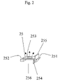
- FIG. 2 shows the basic structure of the present invention with a pliable, releasable clip for covering the LED.
- FIG. 3 shows the pliable cover of the clip before latching to the LED module.
- FIG. 4 shows how the cover of the clip latches to the LED module.
- FIG. 5 shows another version of FIG. 3 , wherein the LED is glued to the cover of the clip.
- FIG. 6 shows a second embodiment of the present invention wherein an array of LEDs are clipped to a display panel.
- FIG. 7 shows a third embodiment of the present invention, wherein two latches are used to clip the LED in place.
- FIG. 8 shows a fourth embodiment of the present invention, wherein a lens is placed in front of the LED to diversify, to parallelize, or to focus the emitted light.
- FIG. 9 shows a fifth embodiment of the present invention, wherein the bottom of the clip cover is of L-shape.
- FIG. 2 shows the basic structure of the present invention.
- a pliable metallic cover clip 25 with a window 253 is used as clip over a LED 20 as shown in FIG. 3 .
- the cover has two flanges 251 , 253 to form an inverted U-shaped groove 256 .
- the flange 252 has a step.
- the flange 251 has a V-shaped cantilever 254 and a protruding handle 255 which forms a step with the flange 251 .
- the handle 255 is pressed toward the left side flange 252 , the V-shaped cantilever 254 is compressed.
- the clip 25 has an inverted U-shaped bottom groove 256 for holding a LED 20 .
- the LED 20 can be a semiconductor chip or a diode lamp.
- FIG. 3 shows the installation of the clip 25 in a LED module.
- a LED 20 is mounted on a bottom metallic plate 22 , which serves as terminal for a surface mount module for the LED.
- a top metallic plate 21 which serves as another terminal for the LED has an opening for the insertion of the clip 25 , is supported by insulators 23 in the space 26 over the bottom metallic plate 22 .
- the top plate 21 has a window over the LED 20 to allow light transmission from the LED 20 .
- the clip 25 engages one edge of the window of plate 21 at the step of the flange 252 .
- FIG. 3 shows the position of the clip 25 before latching to the top metallic plate 21 with the right side flange 251 dangling, and the LED 20 uncovered.
- FIG. 4 shows the clip 25 being lowered to contact the top electrode of the LED 20 .
- the right flange 251 is latched under the top metallic plate 21 at the step of the V-shaped cantilever 254 .
- the latch is positioned by pushing the clip 25 against the space 26 to allow the V-shaped cantilever 254 to slide into the space 26 between the insulators 23 under the window 253 .
- the clip 25 presses against the LED 20 to lock the LED 20 in place and to make electrical contact with the top electrode of the LED. Since the cover of the clip 25 is made of thin pliable metal sheet, the pressure exerted by the clip only causes soft landing of the LED 20 over the bottom plate 22 .
- FIG. 5 shows a modification of FIG. 4 .
- the LED 20 is glued to the clip 25 instead of lying over the bottom metal plate 22 .
- Other reference numerals refer to the corresponding parts in FIG. 4 .
- FIG. 6 shows a second embodiment of the present invention.
- An array of the LED 20 and the clip 25 shown in FIG. 5 is mounted over a display panel 261 .
- the LED modules are mounted over a common bottom plate 22 and latched between parallel rails of top metal plates 21 , which is insulated from the bottom plates 22 by insulating spacers 23 .
- the LED 20 with the clip 25 can be inserted in the space 26 uniformly or selectively to form specific patterns or characters so as to function as a commercial advertisement light board.
- FIG. 7 shows a third embodiment of the present invention.
- the clip 35 has two symmetrical flanges instead of a single flange shown in FIG. 2 .
- Each cantilever flange has a handle 255 .
- To latch the clip 25 for holding the LED 20 in place, the two handles are pushed toward each other for sliding the clip 25 over the LED 20 .
- the other parts of the structure are the same as that in FIG. 4 .
- FIG. 8 shows a fourth embodiment of the present invention.
- a lens 201 is mounted over the LED 20 in the structure shown in FIG. 7 .
- the lens can focus, parallelize, or diversify the light emitted from the LED 20 .
- FIG. 9 shows a fifth embodiment of the present invention.
- an L-shaped bottom plate 456 of the clip 45 is used.
- an elastic spring (not shown in the Figures) can be inserted between the LED and the cover 256 or between the LED and the lower metal plate 22 .
Abstract
Description
Claims (13)
Priority Applications (1)
| Application Number | Priority Date | Filing Date | Title |
|---|---|---|---|
| US11/082,131 US6998650B1 (en) | 2005-03-17 | 2005-03-17 | Replaceable light emitting diode module |
Applications Claiming Priority (1)
| Application Number | Priority Date | Filing Date | Title |
|---|---|---|---|
| US11/082,131 US6998650B1 (en) | 2005-03-17 | 2005-03-17 | Replaceable light emitting diode module |
Publications (1)
| Publication Number | Publication Date |
|---|---|
| US6998650B1 true US6998650B1 (en) | 2006-02-14 |
Family
ID=35767921
Family Applications (1)
| Application Number | Title | Priority Date | Filing Date |
|---|---|---|---|
| US11/082,131 Active US6998650B1 (en) | 2005-03-17 | 2005-03-17 | Replaceable light emitting diode module |
Country Status (1)
| Country | Link |
|---|---|
| US (1) | US6998650B1 (en) |
Cited By (55)
| Publication number | Priority date | Publication date | Assignee | Title |
|---|---|---|---|---|
| US20060232966A1 (en) * | 2005-04-15 | 2006-10-19 | Jiahn-Chang Wu | Light unit display |
| US20070217184A1 (en) * | 2006-03-16 | 2007-09-20 | James Berry | LED light assembly |
| US20070267964A1 (en) * | 2006-05-18 | 2007-11-22 | Jiahn-Chang Wu | A Light Unit with Staggered Electrodes |
| US20080130275A1 (en) * | 2006-12-01 | 2008-06-05 | Cree, Inc. | LED Socket and Replaceable LED Assemblies |
| US20090002984A1 (en) * | 2007-06-28 | 2009-01-01 | Ama Precision Inc. | Illumination device and optical element fixing structure |
| EP2010819A2 (en) * | 2006-04-21 | 2009-01-07 | Cree Inc. | Light emitting diode packages |
| US20090097249A1 (en) * | 2007-10-16 | 2009-04-16 | Foxsemicon Integrated Technology, Inc. | Light emitting diode based light source assembly |
| US20090146918A1 (en) * | 2007-12-11 | 2009-06-11 | Kline Daniel S | Large scale LED display |
| US20090147028A1 (en) * | 2007-12-11 | 2009-06-11 | Sefton Robert J | Data and power distribution system and method for a large scale display |
| US20090146931A1 (en) * | 2007-12-11 | 2009-06-11 | Hamid Kharrati | Large scale LED display system |
| US20090146917A1 (en) * | 2007-12-11 | 2009-06-11 | Hamid Kharrati | Enumeration system and method for a led display |
| US20090146919A1 (en) * | 2007-12-11 | 2009-06-11 | Kline Daniel S | Large Scale LED Display |
| EP2169458A1 (en) * | 2008-09-26 | 2010-03-31 | Samsung Electronics Co., Ltd. | Backlight unit and liquid crystal display having the same |
| WO2010049517A1 (en) * | 2008-10-31 | 2010-05-06 | Osram Gesellschaft mit beschränkter Haftung | A mounting arrangement for light sources and corresponding method |
| EP2187112A1 (en) * | 2008-11-14 | 2010-05-19 | Société J.F. Cesbron Holding | Method to select LEDs in order to obtain a predetermined spectral distribution and panel with such LEDs |
| DE102009032606A1 (en) * | 2009-07-10 | 2011-01-13 | Osram Opto Semiconductors Gmbh | Optoelectronic component and flat light source |
| WO2011012444A1 (en) * | 2009-07-31 | 2011-02-03 | Osram Gesellschaft mit beschränkter Haftung | Lighting device and method for assembling a lighting device |
| US20110116216A1 (en) * | 2009-11-16 | 2011-05-19 | Chao-Chin Weng | Electronic device |
| DE102010023497A1 (en) | 2010-03-11 | 2011-09-15 | Liebherr-Hausgeräte Lienz Gmbh | Lighting unit for lighting inner space of e.g. refrigerator, has holding profile to accommodate light sources, and holding member to hold holding profile, so that light sources are directly/indirectly fixed in fixed state |
| US20110286231A1 (en) * | 2010-05-20 | 2011-11-24 | Ichikoh Industries, Ltd. | Vehicle lighting device |
| US20120120631A1 (en) * | 2010-11-16 | 2012-05-17 | Shenzhen China Star Optoelectronics Technology Co., Ltd. | Light source heat dissipation structure and backlight module |
| DE202011050098U1 (en) * | 2011-05-11 | 2012-10-04 | Goldbeck Gmbh | Luminaire mounting system for buildings |
| US8403544B1 (en) * | 2011-11-21 | 2013-03-26 | Foxsemicon Integrated Technology, Inc. | Lamp and lamp cover latching structure |
| CN103047622A (en) * | 2011-10-13 | 2013-04-17 | 欧司朗股份有限公司 | Mounting device for lighting sources |
| WO2013072812A1 (en) * | 2011-11-14 | 2013-05-23 | Koninklijke Philips Electronics N.V. | Led spring clamp & retainer |
| WO2013053625A3 (en) * | 2011-10-13 | 2013-06-13 | Osram Ag | Mounting device for lighting sources |
| WO2013160175A1 (en) * | 2012-04-25 | 2013-10-31 | Osram Opto Semiconductors Gmbh | Light-emitting device and method for producing such a device |
| US20140002971A1 (en) * | 2012-06-29 | 2014-01-02 | Fih (Hong Kong) Limited | Surface contact card holder for electronic device |
| CN103727462A (en) * | 2013-12-31 | 2014-04-16 | 苏州思莱特电子科技有限公司 | Imaging lamp |
| US8814418B2 (en) | 2012-01-10 | 2014-08-26 | Industrial Technology Research Institute | Detachable LED module |
| EP2833048A1 (en) * | 2013-07-30 | 2015-02-04 | Zumtobel Lighting GmbH | Light with carrier element and replaceable light module |
| US20150138768A1 (en) * | 2010-08-09 | 2015-05-21 | Cree, Inc. | Lighting devices with removable light engine components, lighting device elements and methods |
| EP2134569B1 (en) * | 2007-03-06 | 2015-09-23 | Journée Lighting, Inc. | Lighting assembly having a heat dissipating housing |
| US20150279833A1 (en) * | 2014-03-25 | 2015-10-01 | Infineon Technologies Ag | Protection Devices |
| DE102014107964A1 (en) * | 2014-06-05 | 2015-12-17 | Osram Opto Semiconductors Gmbh | Optoelectronic component |
| US20160069519A1 (en) * | 2013-04-19 | 2016-03-10 | Shenzhen Xingrisheng Industrial Co., Ltd. | Led illumination device capable of disassembling, assembling, combining and slidably adjusting modules, and control method |
| US9565782B2 (en) | 2013-02-15 | 2017-02-07 | Ecosense Lighting Inc. | Field replaceable power supply cartridge |
| US9568665B2 (en) | 2015-03-03 | 2017-02-14 | Ecosense Lighting Inc. | Lighting systems including lens modules for selectable light distribution |
| USD782093S1 (en) | 2015-07-20 | 2017-03-21 | Ecosense Lighting Inc. | LED luminaire having a mounting system |
| USD782094S1 (en) | 2015-07-20 | 2017-03-21 | Ecosense Lighting Inc. | LED luminaire having a mounting system |
| USD785218S1 (en) | 2015-07-06 | 2017-04-25 | Ecosense Lighting Inc. | LED luminaire having a mounting system |
| US9651227B2 (en) | 2015-03-03 | 2017-05-16 | Ecosense Lighting Inc. | Low-profile lighting system having pivotable lighting enclosure |
| US9651232B1 (en) | 2015-08-03 | 2017-05-16 | Ecosense Lighting Inc. | Lighting system having a mounting device |
| US9651216B2 (en) | 2015-03-03 | 2017-05-16 | Ecosense Lighting Inc. | Lighting systems including asymmetric lens modules for selectable light distribution |
| US9746159B1 (en) | 2015-03-03 | 2017-08-29 | Ecosense Lighting Inc. | Lighting system having a sealing system |
| US9869450B2 (en) | 2015-02-09 | 2018-01-16 | Ecosense Lighting Inc. | Lighting systems having a truncated parabolic- or hyperbolic-conical light reflector, or a total internal reflection lens; and having another light reflector |
| US10113705B2 (en) | 2015-09-17 | 2018-10-30 | Samsung Electronics Co., Ltd. | Light source module and lighting device having the same |
| US10180248B2 (en) | 2015-09-02 | 2019-01-15 | ProPhotonix Limited | LED lamp with sensing capabilities |
| US10190755B2 (en) | 2016-11-15 | 2019-01-29 | Abl Ip Holding Llc | LED board retention |
| US10251279B1 (en) | 2018-01-04 | 2019-04-02 | Abl Ip Holding Llc | Printed circuit board mounting with tabs |
| US10253956B2 (en) | 2015-08-26 | 2019-04-09 | Abl Ip Holding Llc | LED luminaire with mounting structure for LED circuit board |
| US10477636B1 (en) | 2014-10-28 | 2019-11-12 | Ecosense Lighting Inc. | Lighting systems having multiple light sources |
| FR3081673A1 (en) * | 2018-05-22 | 2019-11-29 | Alstom Transport Technologies | ASSEMBLY COMPRISING AT LEAST ONE ELECTRONIC COMPONENT, A SUPPORT AND A FIXING DEVICE |
| US11306897B2 (en) | 2015-02-09 | 2022-04-19 | Ecosense Lighting Inc. | Lighting systems generating partially-collimated light emissions |
| US20220333758A1 (en) * | 2019-06-17 | 2022-10-20 | Lg Innotek Co., Ltd. | Lighting device |
Citations (3)
| Publication number | Priority date | Publication date | Assignee | Title |
|---|---|---|---|---|
| US6542534B1 (en) * | 2000-11-08 | 2003-04-01 | Jds Uniphase Corporation | Field-programmable optical source |
| US20030116838A1 (en) * | 2000-11-15 | 2003-06-26 | Jiahn-Chang Wu | Supporting frame for surface-mount diode package |
| US20050180157A1 (en) * | 2004-01-23 | 2005-08-18 | Koito Manufacturing Co., Ltd. | Lighting unit |
-
2005
- 2005-03-17 US US11/082,131 patent/US6998650B1/en active Active
Patent Citations (3)
| Publication number | Priority date | Publication date | Assignee | Title |
|---|---|---|---|---|
| US6542534B1 (en) * | 2000-11-08 | 2003-04-01 | Jds Uniphase Corporation | Field-programmable optical source |
| US20030116838A1 (en) * | 2000-11-15 | 2003-06-26 | Jiahn-Chang Wu | Supporting frame for surface-mount diode package |
| US20050180157A1 (en) * | 2004-01-23 | 2005-08-18 | Koito Manufacturing Co., Ltd. | Lighting unit |
Cited By (96)
| Publication number | Priority date | Publication date | Assignee | Title |
|---|---|---|---|---|
| US20060232966A1 (en) * | 2005-04-15 | 2006-10-19 | Jiahn-Chang Wu | Light unit display |
| US20080037263A1 (en) * | 2005-04-15 | 2008-02-14 | Jiahn-Chang Wu | Light unit display |
| US7798702B2 (en) * | 2005-04-15 | 2010-09-21 | Jiahn-Chang Wu | Light unit display |
| US7284896B2 (en) * | 2005-04-15 | 2007-10-23 | Jiahn-Chang Wu | Light unit display |
| US20070217184A1 (en) * | 2006-03-16 | 2007-09-20 | James Berry | LED light assembly |
| EP2010819A4 (en) * | 2006-04-21 | 2013-09-11 | Cree Inc | Light emitting diode packages |
| EP2010819A2 (en) * | 2006-04-21 | 2009-01-07 | Cree Inc. | Light emitting diode packages |
| US7518306B2 (en) * | 2006-05-18 | 2009-04-14 | Jiahn-Chang Wu | Light unit with staggered electrodes |
| US20070267964A1 (en) * | 2006-05-18 | 2007-11-22 | Jiahn-Chang Wu | A Light Unit with Staggered Electrodes |
| EP2087555A2 (en) * | 2006-12-01 | 2009-08-12 | Cree Inc. | Led socket and replaceable led assemblies |
| WO2008070421A3 (en) * | 2006-12-01 | 2009-05-07 | Cree Inc | Led socket and replaceable led assemblies |
| EP2087555A4 (en) * | 2006-12-01 | 2013-12-04 | Cree Inc | Led socket and replaceable led assemblies |
| US20080130275A1 (en) * | 2006-12-01 | 2008-06-05 | Cree, Inc. | LED Socket and Replaceable LED Assemblies |
| CN101548436B (en) * | 2006-12-01 | 2012-11-07 | 克里公司 | Led socket and replaceable led assemblies |
| US7549786B2 (en) | 2006-12-01 | 2009-06-23 | Cree, Inc. | LED socket and replaceable LED assemblies |
| EP2134569B1 (en) * | 2007-03-06 | 2015-09-23 | Journée Lighting, Inc. | Lighting assembly having a heat dissipating housing |
| US20090002984A1 (en) * | 2007-06-28 | 2009-01-01 | Ama Precision Inc. | Illumination device and optical element fixing structure |
| US7883240B2 (en) * | 2007-10-16 | 2011-02-08 | Foxsemicon Integrated Technology, Inc. | Light emitting diode based light source assembly |
| US20090097249A1 (en) * | 2007-10-16 | 2009-04-16 | Foxsemicon Integrated Technology, Inc. | Light emitting diode based light source assembly |
| US20090146919A1 (en) * | 2007-12-11 | 2009-06-11 | Kline Daniel S | Large Scale LED Display |
| US8766880B2 (en) | 2007-12-11 | 2014-07-01 | Adti Media, Llc140 | Enumeration system and method for a LED display |
| US20090146918A1 (en) * | 2007-12-11 | 2009-06-11 | Kline Daniel S | Large scale LED display |
| US9135838B2 (en) | 2007-12-11 | 2015-09-15 | ADTI Media, LLC | Large scale LED display |
| US8922458B2 (en) | 2007-12-11 | 2014-12-30 | ADTI Media, LLC | Data and power distribution system and method for a large scale display |
| US8803766B2 (en) | 2007-12-11 | 2014-08-12 | Adti Media, Llc140 | Large scale LED display |
| US8648774B2 (en) | 2007-12-11 | 2014-02-11 | Advance Display Technologies, Inc. | Large scale LED display |
| US20090147028A1 (en) * | 2007-12-11 | 2009-06-11 | Sefton Robert J | Data and power distribution system and method for a large scale display |
| WO2009076116A1 (en) * | 2007-12-11 | 2009-06-18 | Advance Display Technologies, Inc. | Large scale led display |
| US20090146931A1 (en) * | 2007-12-11 | 2009-06-11 | Hamid Kharrati | Large scale LED display system |
| US20110215992A1 (en) * | 2007-12-11 | 2011-09-08 | Adti Media, Llc140 | Large scale led display |
| US8599108B2 (en) | 2007-12-11 | 2013-12-03 | Adti Media, Llc140 | Large scale LED display |
| US20110221662A1 (en) * | 2007-12-11 | 2011-09-15 | Adti Media, Llc140 | Large scale led display |
| US8558755B2 (en) | 2007-12-11 | 2013-10-15 | Adti Media, Llc140 | Large scale LED display system |
| US20090146917A1 (en) * | 2007-12-11 | 2009-06-11 | Hamid Kharrati | Enumeration system and method for a led display |
| US9378671B2 (en) | 2007-12-11 | 2016-06-28 | Adti Media Llc | Large scale LED display |
| EP2397888A1 (en) * | 2008-09-26 | 2011-12-21 | Samsung Electronics Co., Ltd. | Backlight unit and liquid crystal display having the same |
| EP2169458A1 (en) * | 2008-09-26 | 2010-03-31 | Samsung Electronics Co., Ltd. | Backlight unit and liquid crystal display having the same |
| US20100079697A1 (en) * | 2008-09-26 | 2010-04-01 | Samsung Electronics Co., Ltd. | Backlight unit and liquid crystal display having the same |
| US8384846B2 (en) | 2008-09-26 | 2013-02-26 | Samsung Electronics Co., Ltd. | Backlight unit and liquid crystal display having the same |
| CN101684908B (en) * | 2008-09-26 | 2015-01-14 | 三星电子株式会社 | Backlight unit and liquid crystal display having the same |
| WO2010049517A1 (en) * | 2008-10-31 | 2010-05-06 | Osram Gesellschaft mit beschränkter Haftung | A mounting arrangement for light sources and corresponding method |
| EP2187112A1 (en) * | 2008-11-14 | 2010-05-19 | Société J.F. Cesbron Holding | Method to select LEDs in order to obtain a predetermined spectral distribution and panel with such LEDs |
| FR2938627A1 (en) * | 2008-11-14 | 2010-05-21 | J F Cesbron Holding Soc | METHOD FOR REPRODUCING A LIGHT SPECTRUM WITH LEDS AND CORRESPONDING LED PANEL |
| DE102009032606A1 (en) * | 2009-07-10 | 2011-01-13 | Osram Opto Semiconductors Gmbh | Optoelectronic component and flat light source |
| WO2011012444A1 (en) * | 2009-07-31 | 2011-02-03 | Osram Gesellschaft mit beschränkter Haftung | Lighting device and method for assembling a lighting device |
| CN102472478A (en) * | 2009-07-31 | 2012-05-23 | 欧司朗股份有限公司 | Lighting device and method for assembling a lighting device |
| US20110116216A1 (en) * | 2009-11-16 | 2011-05-19 | Chao-Chin Weng | Electronic device |
| DE102010023497A1 (en) | 2010-03-11 | 2011-09-15 | Liebherr-Hausgeräte Lienz Gmbh | Lighting unit for lighting inner space of e.g. refrigerator, has holding profile to accommodate light sources, and holding member to hold holding profile, so that light sources are directly/indirectly fixed in fixed state |
| DE102010023497B4 (en) | 2010-03-11 | 2018-08-16 | Liebherr-Hausgeräte Lienz Gmbh | lighting unit |
| US20110286231A1 (en) * | 2010-05-20 | 2011-11-24 | Ichikoh Industries, Ltd. | Vehicle lighting device |
| US9644822B2 (en) * | 2010-08-09 | 2017-05-09 | Cree, Inc. | Lighting devices with removable light engine components, lighting device elements and methods |
| US20150138768A1 (en) * | 2010-08-09 | 2015-05-21 | Cree, Inc. | Lighting devices with removable light engine components, lighting device elements and methods |
| US9004721B2 (en) * | 2010-11-16 | 2015-04-14 | Shenzhen China Star Optoelectronics Technology Co., Ltd. | Light source heat dissipation structure and backlight module |
| US20120120631A1 (en) * | 2010-11-16 | 2012-05-17 | Shenzhen China Star Optoelectronics Technology Co., Ltd. | Light source heat dissipation structure and backlight module |
| DE202011050098U1 (en) * | 2011-05-11 | 2012-10-04 | Goldbeck Gmbh | Luminaire mounting system for buildings |
| WO2013053625A3 (en) * | 2011-10-13 | 2013-06-13 | Osram Ag | Mounting device for lighting sources |
| US20140268834A1 (en) * | 2011-10-13 | 2014-09-18 | Osram Gmbh | Mounting device for lighting sources |
| CN103890487A (en) * | 2011-10-13 | 2014-06-25 | 欧司朗股份有限公司 | Mounting device for lighting sources |
| US9765952B2 (en) * | 2011-10-13 | 2017-09-19 | Osram Gmbh | Mounting device for lighting sources |
| CN103047622A (en) * | 2011-10-13 | 2013-04-17 | 欧司朗股份有限公司 | Mounting device for lighting sources |
| WO2013072812A1 (en) * | 2011-11-14 | 2013-05-23 | Koninklijke Philips Electronics N.V. | Led spring clamp & retainer |
| US8403544B1 (en) * | 2011-11-21 | 2013-03-26 | Foxsemicon Integrated Technology, Inc. | Lamp and lamp cover latching structure |
| US8814418B2 (en) | 2012-01-10 | 2014-08-26 | Industrial Technology Research Institute | Detachable LED module |
| WO2013160175A1 (en) * | 2012-04-25 | 2013-10-31 | Osram Opto Semiconductors Gmbh | Light-emitting device and method for producing such a device |
| US9599319B2 (en) | 2012-04-25 | 2017-03-21 | Osram Opto Semiconductors Gmbh | Light-emitting device including a semiconductor component and an optical element and method for manufacturing thereof |
| US20140002971A1 (en) * | 2012-06-29 | 2014-01-02 | Fih (Hong Kong) Limited | Surface contact card holder for electronic device |
| CN103515781A (en) * | 2012-06-29 | 2014-01-15 | 深圳富泰宏精密工业有限公司 | Chip card retaining structure |
| US9565782B2 (en) | 2013-02-15 | 2017-02-07 | Ecosense Lighting Inc. | Field replaceable power supply cartridge |
| US20160069519A1 (en) * | 2013-04-19 | 2016-03-10 | Shenzhen Xingrisheng Industrial Co., Ltd. | Led illumination device capable of disassembling, assembling, combining and slidably adjusting modules, and control method |
| US9939116B2 (en) * | 2013-04-19 | 2018-04-10 | Shenzhen Xingrisheng Industrial Co., Ltd. | LED illumination device capable of disassembling, assembling, combining and slidably adjusting modules, and control method |
| EP2833048A1 (en) * | 2013-07-30 | 2015-02-04 | Zumtobel Lighting GmbH | Light with carrier element and replaceable light module |
| CN103727462A (en) * | 2013-12-31 | 2014-04-16 | 苏州思莱特电子科技有限公司 | Imaging lamp |
| US20150279833A1 (en) * | 2014-03-25 | 2015-10-01 | Infineon Technologies Ag | Protection Devices |
| US9437589B2 (en) * | 2014-03-25 | 2016-09-06 | Infineon Technologies Ag | Protection devices |
| DE102014107964A1 (en) * | 2014-06-05 | 2015-12-17 | Osram Opto Semiconductors Gmbh | Optoelectronic component |
| US10477636B1 (en) | 2014-10-28 | 2019-11-12 | Ecosense Lighting Inc. | Lighting systems having multiple light sources |
| US9869450B2 (en) | 2015-02-09 | 2018-01-16 | Ecosense Lighting Inc. | Lighting systems having a truncated parabolic- or hyperbolic-conical light reflector, or a total internal reflection lens; and having another light reflector |
| US11614217B2 (en) | 2015-02-09 | 2023-03-28 | Korrus, Inc. | Lighting systems generating partially-collimated light emissions |
| US11306897B2 (en) | 2015-02-09 | 2022-04-19 | Ecosense Lighting Inc. | Lighting systems generating partially-collimated light emissions |
| US9651216B2 (en) | 2015-03-03 | 2017-05-16 | Ecosense Lighting Inc. | Lighting systems including asymmetric lens modules for selectable light distribution |
| US9651227B2 (en) | 2015-03-03 | 2017-05-16 | Ecosense Lighting Inc. | Low-profile lighting system having pivotable lighting enclosure |
| US9746159B1 (en) | 2015-03-03 | 2017-08-29 | Ecosense Lighting Inc. | Lighting system having a sealing system |
| US9568665B2 (en) | 2015-03-03 | 2017-02-14 | Ecosense Lighting Inc. | Lighting systems including lens modules for selectable light distribution |
| USD785218S1 (en) | 2015-07-06 | 2017-04-25 | Ecosense Lighting Inc. | LED luminaire having a mounting system |
| USD782094S1 (en) | 2015-07-20 | 2017-03-21 | Ecosense Lighting Inc. | LED luminaire having a mounting system |
| USD782093S1 (en) | 2015-07-20 | 2017-03-21 | Ecosense Lighting Inc. | LED luminaire having a mounting system |
| US9651232B1 (en) | 2015-08-03 | 2017-05-16 | Ecosense Lighting Inc. | Lighting system having a mounting device |
| US10253956B2 (en) | 2015-08-26 | 2019-04-09 | Abl Ip Holding Llc | LED luminaire with mounting structure for LED circuit board |
| US10180248B2 (en) | 2015-09-02 | 2019-01-15 | ProPhotonix Limited | LED lamp with sensing capabilities |
| US10240771B2 (en) | 2015-09-02 | 2019-03-26 | ProPhotonix Limited | LED lamp with sensing capabilities |
| US10113705B2 (en) | 2015-09-17 | 2018-10-30 | Samsung Electronics Co., Ltd. | Light source module and lighting device having the same |
| US10190755B2 (en) | 2016-11-15 | 2019-01-29 | Abl Ip Holding Llc | LED board retention |
| US10251279B1 (en) | 2018-01-04 | 2019-04-02 | Abl Ip Holding Llc | Printed circuit board mounting with tabs |
| FR3081673A1 (en) * | 2018-05-22 | 2019-11-29 | Alstom Transport Technologies | ASSEMBLY COMPRISING AT LEAST ONE ELECTRONIC COMPONENT, A SUPPORT AND A FIXING DEVICE |
| US20220333758A1 (en) * | 2019-06-17 | 2022-10-20 | Lg Innotek Co., Ltd. | Lighting device |
| US11732861B2 (en) * | 2019-06-17 | 2023-08-22 | Lg Innotek Co., Ltd. | Lighting device |
Similar Documents
| Publication | Publication Date | Title |
|---|---|---|
| US6998650B1 (en) | Replaceable light emitting diode module | |
| JP5669188B2 (en) | LED lighting assembly | |
| JP4618310B2 (en) | LIGHTING DEVICE, LIGHTING DEVICE ASSEMBLY METHOD, AND LIQUID CRYSTAL DISPLAY DEVICE | |
| US9054453B2 (en) | Connector | |
| KR101318251B1 (en) | Single body type lamp socket, backlight assembly and display device having the same | |
| US9373922B2 (en) | LED illumination device with edge connector | |
| CN104896397B (en) | LED lamp | |
| KR101615839B1 (en) | Solid state lighting assembly | |
| KR101399168B1 (en) | Back light assembly, relay connector, and back light unit | |
| JP4867877B2 (en) | Surface-emitting light fixture | |
| KR20090026841A (en) | Light unit and display apparatus having thereof | |
| KR101680517B1 (en) | LED module combination | |
| JP2013106042A (en) | Led socket assembly | |
| JPH0723854Y2 (en) | Holder for keyboard lighting element | |
| CN210404105U (en) | Electric connecting device and display module | |
| US20150181657A1 (en) | Illuminant device and lighting module thereof | |
| KR101791149B1 (en) | Light emitting diode illumination lamp | |
| CN103016971A (en) | Illumination device | |
| US7405943B2 (en) | Electronic appliance comprising a floating circuit carrier | |
| US20100321925A1 (en) | Liquid crystal module | |
| KR100844449B1 (en) | Lamp lighting apparatus for lcd backlight using conductivity rubber | |
| KR101633907B1 (en) | Detachable led light apparatus | |
| CN103047624B (en) | Light source fixing structure | |
| KR20140071852A (en) | Holder for semiconductor light device, semiconductor light device module and illuminating using the same | |
| US11274813B2 (en) | Light source switching module, light source assembly and lighting lamp |
Legal Events
| Date | Code | Title | Description |
|---|---|---|---|
| STCF | Information on status: patent grant |
Free format text: PATENTED CASE |
|
| FPAY | Fee payment |
Year of fee payment: 4 |
|
| FEPP | Fee payment procedure |
Free format text: PAT HOLDER NO LONGER CLAIMS SMALL ENTITY STATUS, ENTITY STATUS SET TO UNDISCOUNTED (ORIGINAL EVENT CODE: STOL); ENTITY STATUS OF PATENT OWNER: LARGE ENTITY |
|
| AS | Assignment |
Owner name: CHENG KUNG CAPITAL, LLC, DELAWARE Free format text: ASSIGNMENT OF ASSIGNORS INTEREST;ASSIGNOR:WU, JIAHN-CHANG;REEL/FRAME:026869/0640 Effective date: 20110805 |
|
| FEPP | Fee payment procedure |
Free format text: ENTITY STATUS SET TO UNDISCOUNTED (ORIGINAL EVENT CODE: BIG.); ENTITY STATUS OF PATENT OWNER: LARGE ENTITY |
|
| FPAY | Fee payment |
Year of fee payment: 8 |
|
| FPAY | Fee payment |
Year of fee payment: 12 |