US6999617B1 - Image processing method and apparatus - Google Patents
Image processing method and apparatus Download PDFInfo
- Publication number
- US6999617B1 US6999617B1 US09/358,408 US35840899A US6999617B1 US 6999617 B1 US6999617 B1 US 6999617B1 US 35840899 A US35840899 A US 35840899A US 6999617 B1 US6999617 B1 US 6999617B1
- Authority
- US
- United States
- Prior art keywords
- viewing condition
- color
- colorimetric data
- data
- viewing
- Prior art date
- Legal status (The legal status is an assumption and is not a legal conclusion. Google has not performed a legal analysis and makes no representation as to the accuracy of the status listed.)
- Expired - Fee Related
Links
Images


Classifications
-
- H—ELECTRICITY
- H04—ELECTRIC COMMUNICATION TECHNIQUE
- H04N—PICTORIAL COMMUNICATION, e.g. TELEVISION
- H04N1/00—Scanning, transmission or reproduction of documents or the like, e.g. facsimile transmission; Details thereof
- H04N1/46—Colour picture communication systems
- H04N1/56—Processing of colour picture signals
- H04N1/60—Colour correction or control
- H04N1/6083—Colour correction or control controlled by factors external to the apparatus
- H04N1/6088—Colour correction or control controlled by factors external to the apparatus by viewing conditions, i.e. conditions at picture output
-
- G—PHYSICS
- G06—COMPUTING; CALCULATING OR COUNTING
- G06T—IMAGE DATA PROCESSING OR GENERATION, IN GENERAL
- G06T11/00—2D [Two Dimensional] image generation
- G06T11/001—Texturing; Colouring; Generation of texture or colour
-
- H—ELECTRICITY
- H04—ELECTRIC COMMUNICATION TECHNIQUE
- H04N—PICTORIAL COMMUNICATION, e.g. TELEVISION
- H04N1/00—Scanning, transmission or reproduction of documents or the like, e.g. facsimile transmission; Details thereof
- H04N1/46—Colour picture communication systems
- H04N1/56—Processing of colour picture signals
- H04N1/60—Colour correction or control
- H04N1/6083—Colour correction or control controlled by factors external to the apparatus
- H04N1/6086—Colour correction or control controlled by factors external to the apparatus by scene illuminant, i.e. conditions at the time of picture capture, e.g. flash, optical filter used, evening, cloud, daylight, artificial lighting, white point measurement, colour temperature
Definitions
- the present invention relates to an image processing apparatus and method, and more particularly, to an image processing apparatus and method for performing color matching according to ambient light.
- FIG. 1 is a conceptual view of general color matching.
- Input RGB data is converted by an input profile to XYZ data of a color space which does not depend on any devices. Since an output device cannot express colors outside the color reproduction range of the output device, gamut mapping is performed on the inputted data, which has been converted to the data in the device-independent color space, such that all colors of the inputted data fall within the color reproduction range of the output device. After the gamut mapping is performed, the inputted data is converted from the device-independent color space to CMYK data of a color space which is dependent on the output device.
- XYZ values of the viewed sample naturally vary.
- the XYZ values under various illuminants are predicted by conversion methods such as (1) scaling operation, (2) Von Kries conversion, and (3) prediction formula using a color appearance model.
- XYZ values under a reference white point W1 are converted to XYZ values under a reference white point W2 at a ratio of W2/W1. If this operation method is applied to the Lab uniform color space, the Lab values under W1 become equal to the Lab values under W2.
- XYZ values under the reference white point W1 are converted to XYZ values under the reference white point W2 at a ratio of W2′/W1′ in a human color perception space PQR. If this conversion method is applied to the Lab uniform color space, the Lab values under W1 do not become equal to the Lab values under W2.
- a color appearance model which is a conversion method such as CIE CAM 97s using the human color perception space QMH (or JCH) is employed.
- Q for represents brightness
- M represents colorfulness
- H represents hue quadrature or hue angle.
- J for JCH represents lightness
- C represents chroma
- H represents hue quadrature or hue angle.
- the present invention is made in consideration of the above situation, and has as its object to provide an image processing apparatus and method which enable excellent color reproduction under different viewing conditions.
- the present invention provides an image processing method comprising the steps of: obtaining a profile having a plurality of colorimetric data which depend on a plurality of light sources; inputting a viewing condition; selecting colorimetric data from the plurality of colorimetric data in accordance with the input viewing condition; and conjecturing calorimetric data corresponding to the input viewing condition based on the selected calorimetric data.
- Another object of the present invention is to provide an image processing apparatus and method which efficiently perform excellent color reproduction processing under different viewing conditions.
- the present invention provides an image processing method comprising the steps of: obtaining a profile having a plurality of calorimetric data which depend on a plurality of light sources; inputting a viewing condition; selecting colorimetric data from the plurality of colorimetric data in accordance with the input viewing condition; conjecturing colorimetric data corresponding to the input viewing condition based on the selected calorimetric data; and caching the conjectured colorimetric data to the profile.
- FIG. 1 is a conceptual view of color matching
- FIG. 2 is an explanatory view showing a concept of the present invention
- FIG. 3 is a block diagram showing the functional configuration of a first embodiment of the present invention.
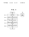
- FIG. 4 is a flowchart showing the process of reconstructing a conversion LUT which corresponds to an ambient light
- FIG. 5 is a flowchart showing the process of updating a conversion LUT so as to correspond to an ambient light
- FIG. 6 is a flowchart showing the process of performing gamut mapping in the color space JCH or QMH;
- FIG. 7 shows a dodecahedron for approximating a color reproduction range
- FIGS. 8A and 8B are conceptual views of gamut mapping in the JCH color perception space
- FIGS. 9A and 9B are conceptual views of gamut mapping in the QMH color perception space
- FIGS. 10A and 10B are conceptual views of gamut mapping performed between different devices
- FIG. 11 is a flowchart showing the process of reconstructing a conversion LUT which corresponds to an ambient light
- FIG. 12 is a conceptual view of color matching processing
- FIG. 13 is a conceptual view of color matching according to a second embodiment of the present invention.
- FIG. 14 is a flowchart showing the process of performing gamut mapping in the color space JCH or QMH according to the second embodiment
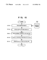
- FIG. 15 is a flowchart showing the process of reconstructing a conversion LUT which corresponds to an ambient light according to the second embodiment
- FIG. 16 is a conceptual view of color matching according to a third embodiment of the present invention.
- FIG. 17 is a flowchart showing the process of updating a conversion LUT so as to correspond to an ambient light in the second embodiment
- FIG. 18 is a block diagram showing a construction of an apparatus which realizes the functional configuration shown in FIG. 3 ;
- FIG. 19 is an explanatory block diagram of a color appearance model used in the embodiments of the present invention.
- FIG. 20 is a conceptual view of a profile storing XYZ values of a white point under different illuminants, device-dependent RGB values of a color target, XYZ values corresponding to the color target under respective illuminants;
- FIG. 21 shows a spectral distribution of a standard illuminant
- FIG. 22 is a flowchart showing the process of conjecturing a calorimetric value from the colorimetric data for plural illuminants
- FIG. 23 shows an example in which a LUT, provided for mutually converting a device-independent color space under a viewing condition to a device-dependent color space, is stored in the ICC profile;
- FIG. 24 is a flowchart showing caching processing
- FIG. 25 shows an example of a Graphic User Interface (GUI) for setting a parameter of a viewing condition according to a sixth embodiment of the present invention
- FIG. 26 shows an example of a GUI which enables setting of a user level
- FIG. 27 shows the GUI of FIG. 26 , whose user level is set in “professional level.”
- a color perceived by human visual system is different depending on conditions, such as the difference in lighting or a background on which a stimulus as a viewing subject is placed, even if the characteristic of light entering the eye is the same.
- a white color illuminated by an incandescent lamp, is not perceived as red as the characteristic of light entering the eye, but is perceived as white.
- a white color placed on a black background is perceived brighter than a white color placed on a bright background.
- the former phenomenon is known as chromatic adaptation and the latter is known as a contrast.
- colors must be displayed not by the XYZ color system, but by the volume corresponding to a physiological activity level of visual cells distributed on the retina.
- the CIE Commission Internationale de l'Eclairage
- This color appearance model utilizes color perception correlation values, which are H (hue), J (lightness) and C (chroma), or H (hue), Q (brightness) and M (colorfulness), as physiological three primary colors of color vision, and is considered as a color display method which do not depend upon viewing conditions. By reproducing colors so as to match the values of H, J and C or H, Q and M between devices, it is possible to solve the problem of different viewing conditions in an input image and output image.
- step S 160 LA indicative of a luminance of an adaptive visual field (cd/m 2 ) (normally, 20% of white luminance in the adaptive visual field is selected), XYZ indicative of relative tristimulus values of a sample under an illuminant condition, XwYwZw indicative of relative tristimulus values of a white light under the illuminant condition, and Yb indicative of a relative luminance of a background under the illuminant condition are set as the viewing condition information of an image to be inputted.
- a constant c indicative of an impact of surround is set as the viewing condition information of the input image in step S 170 .
- the XYZ are converted based on the Bradford's three primary colors, which are considered as human physiological three primary colors, to obtain RGB corresponding to Bradford's cone response (step S 100 ). Since human vision does not always completely adapt to the viewing illuminant, a variable D indicative of adaptability is obtained based on a luminance level and a viewing condition (LA and F). Based on the obtained variable D and XwYwZw, incomplete adaptation processing is performed on RGB to be converted to RcGcBc (step S 110 ).
- RcGcBc is converted based on Hunt-Pointer-Estevez's three primary colors, which are considered as human physiological three primary colors, to obtain R′G′B′ corresponding to Hunt-Pointer-Estevez's cone response (step S 120 ).
- the adaptability of R′G′B′ is estimated by a stimulus intensity level to obtain R′aG′aB′a corresponding to an adapted cone response which corresponds to both the sample and white (step S 130 ).
- non-linear response compression is performed by using a variable FL which is calculated based on the luminance LA of the adaptive visual field.
- Opposite color responses a and b of red-green and yellow-blue are calculated from R′aG′aB′a (step S 140 ), and a hue H is calculated from the opposite color responses a and b and a eccentricity factor (step S 150 ).
- a background inducing coefficient n is calculated from Yw and the relative luminance Yb of the background.
- achromatic color responses A and Aw with respect to both the sample and white are calculated (step S 190 ).
- Lightness J is calculated by using a coefficient z, calculated from the background inducing coefficient n and lightness contrast factor FLL, and the achromatic color responses A and Aw as well as the impact of surround constant c (step S 151 ).
- a saturation S is calculated from the chromatic induction factor NL (step S 153 ), then from the saturation S and lightness J, a chroma C is calculated (step S 152 ), and a brightness Q is calculated from the lightness J and achromatic color response Aw for white (step S 154 ).
- a colorfulness M is calculated from the variable FL and impact of surround constant c (step S 155 ).
- reference numeral 11 denotes a conversion matrix or a conversion lookup table (LUT) for converting data which is dependent on an input device (hereinafter referred to as input-device-dependent data) to data of the device-independent color space (hereinafter referred to as input-independent data), which accords to a white point of ambient light at the time of viewing an image formed on an original.
- Reference numeral 12 denotes a forward converter (CAM) of a color appearance model for converting data, obtained from the conversion LUT 11 , to human color perception color space JCh or QMh.
- CAM forward converter
- Reference numeral 13 denotes a relative color perception space JCh (or JCH) relative to the reference white of an ambient light; and 14 , an absolute color perception space QMh (or QMH) whose size changes in accordance with an illuminance level.
- Reference numeral 15 denotes an inverse converter of a color appearance model for converting data of the human's color perception space JCh or QMh to data of the device independent color space (hereinafter referred to as output-independent data), which accords to a white point of ambient light at the time of viewing an image formed on a printout.
- Reference numeral 16 denotes a conversion LUT for converting data, obtained from the inverse converter 15 , to data which is dependent on an output device (hereinafter referred to as output-device-dependent data).
- the white point of ambient light under a viewing condition is different from a white point of the standard illuminant at the time of colorimetry of a color target or color patch or the like.
- the standard illuminant used at the time of colorimetry is D50 or D65, but an ambient light for actually viewing an image is not always D50 or D65 in a light booth.
- An illumination light from an incandescent lamp or fluorescent light, or a combination of illumination light and sunlight are often used as the ambient light in which the image is actually viewed.
- an illuminant characteristic of an ambient light under a viewing condition is assumed as D50, D65 and D93 to simplify the description, in reality, XYZ values of a white point on a medium is set as a white point.
- FIG. 3 is a block diagram showing a functional configuration of the present embodiment.
- reference numeral 41 denotes a data generation portion for generating data, which is dependent on the viewing condition 1 of a data input side, based on an input profile 42 and the viewing condition 1.
- Reference numeral 43 denotes a gamut mapping mode selection portion for selecting whether the gamut mapping is performed in the JCH color perception space or in the QMH color perception space in accordance with designation by a user or designation by the profile.
- Reference numerals 44 and 45 denote gamut mapping portions respectively for performing gamut mapping on data in the JCH or QMH color perception space in accordance with an output profile 46 .
- Reference numeral 47 denotes a data generation portion for generating data, which is dependent on a viewing condition 2 of an image output side, based on the output profile 46 and viewing condition 2.
- Reference numeral 48 denotes a color matching portion for performing color matching by utilizing the data which is dependent on the viewing condition 1, the gamut mapped data, the data which is dependent on the viewing condition 2, and color appearance model.
- FIG. 18 is a block diagram showing a construction of an apparatus which realizes the functional configuration shown in FIG. 3 .
- the apparatus shown in FIG. 18 is realized by supplying a general computer apparatus, such as a personal computer or the like, with software which realizes the function shown in FIG. 3 .
- the software which realizes the function of the present embodiment may be included in the Operating System (OS) which is the basic system software of the computer apparatus, or may be provided, for instance, as a driver software of an input/output device independently of the Os.
- OS Operating System
- a CPU 100 controls operation of the entire apparatus according to a program stored in a ROM 101 and hard disk (HD) 106 and the like, by utilizing a RAM 102 as a work memory, and executes various processing including the processing related to the above-described color matching.
- An input interface 103 is provided to connect an input device 104 ;
- a hard disk interface 105 is provided to connect the HD 106 ;
- a video interface 107 is provided to connect a monitor 108 ; and an output interface 109 is provided to connect an output device 110 .
- the input device includes an image sensing device such as a digital still camera or a digital video camera or the like, and various image input devices including an image reader such as an image scanner or film scanner or the like.
- the output device includes a color monitor such as a CRT or LCD or the like, and an image output device such as a color printer or film recorder or the like.
- a general interface is utilized as the interface of the present embodiment.
- a serial interface such as RS232C, RS422 or the like, a serial bus interface such as IEEE 1394, Universal Serial Bus (USB) or the like, and a parallel interface such as SCSI, GPIB, centronics or the like, are applicable.
- Input/output profiles for color matching are stored in the HD 106 .
- the storage medium is not limited to hard disk, but may be an optical disk such as a magneto-optical disk (MO) or the like.
- the conversion LUT 11 is generated by the data generation portion 41 .
- Methods of generating the conversion LUT 11 include: a method of reconstructing the conversion LUT 11 so as to correspond to an ambient light, based on a relation between XYZ values (or Lab values) of a color target and RGB values of an input device as shown in FIG. 4 ; and a method of updating a conversion LUT stored in the input profile 42 , which is provided for converting an RGB space dependent on a device to XYZ color space, to the conversion LUT 11 which corresponds to the ambient light.
- FIG. 4 is a flowchart showing the process of reconstructing the conversion LUT 11 which corresponds to an ambient light.
- a profile designated by a user is read from the input profile 42 in step S 51 .
- XYZ values (or Lab values) of the color target and XYZ-to-RGB relation data, which associates the XYZ values with RGB values for a case of reading the color target by an input device, are stored in advance in the profile.
- the XYZ-to-RGB relation data is obtained from the profile in step S 52 . Since the profile includes a viewing condition 1, the viewing condition 1 is obtained from the profile in step S 53 .
- the XYZ values of the XYZ-to-RGB relation data, obtained in step S 52 employ as a reference, D50 or D65 indicative of a reference light at the time of colorimetry of the color target. Therefore, the XYZ values of the colorimetric illuminant reference must be corrected to XYZ values of an ambient light reference.
- step S 54 by using the color appearance model, the XYZ values of the calorimetric illuminant reference are converted to the color perception space JCH based on a colorimetric condition, i.e., the white point of D50 illuminant, an illuminance level, and the state of ambient light, and then the converted values in the color perception space JCH are converted back to XYZ values based on the viewing condition 1 different from the colorimetric condition, e.g., the white point of D65 illuminant, an illuminance level, and the state of ambient light.
- a colorimetric condition i.e., the white point of D50 illuminant, an illuminance level, and the state of ambient light
- the converted values in the color perception space JCH are converted back to XYZ values based on the viewing condition 1 different from the colorimetric condition, e.g., the white point of D65 illuminant, an illuminance level, and the state of ambient light.
- step S 55 an RGB-to-XYZ conversion matrix is generated based on the RGB-to-XYZ relation data and optimized by repetition or the like, thereby obtaining the conversion LUT 11 which corresponds to the viewing condition 1.
- FIG. 5 is a flowchart showing the process of updating the conversion LUT, stored in the input profile 42 , to the conversion LUT 11 which corresponds to an ambient light. Note that the steps in FIG. 5 executing the same processing as those in FIG. 4 have the same reference step number, and detailed description thereof is omitted.
- a conversion matrix for performing RGB-to-XYZ conversion, or a conversion LUT (AtoB0 Tag) is stored.
- the RGB-to-XYZ relation data is obtained from the profile in step S 62 .
- step S 54 the relation between XYZ values of the ambient light reference and device RGB values is obtained. Then in step S 66 , the conversion matrix (colorant Tag) or conversion LUT (AtoB0 Tag) in the profile is updated. As a result, a conversion LUT, updated to the conversion LUT 11 corresponding to the viewing condition 1, is obtained.
- FIGS. 4 and 5 provide an example of utilizing the RGB-to-XYZ relation data
- the present invention is not limited to this, but may utilize other device-independent color data such as RGB-to-Lab relation data.
- a gamut mapping mode is selected by a user through a user interface, or automatically selected by Rendering Intent included in the header of a source profile. The following selection is made in the automatic selection according to the profile.
- JCH space 13 is selected, while in a case of absolute color matching, QMH space 14 is selected.
- FIG. 6 is a flowchart showing the process of performing the gamut mapping in the color perception space JCH 13 or color perception space QMH 14 .
- a profile designated by a user is read from the output profile 46 in step S 81 .
- a judgment LUT to which XYZ values or Lab values are inputted, is stored in order to judge inside or outside the color reproduction range (hereinafter referred to as inside/outside judgment of the color reproduction range).
- inside/outside judgment of the color reproduction range the XYZ values employ D50 or D65 which is the characteristic of calorimetric illuminant as a reference, the XYZ values cannot be used directly to make judgment of inside/outside the color reproduction range according to an ambient light.
- CMYK-to-XYZ relation data is obtained in step S 82 from the conversion LUT (AtoB0 Tag or the like), stored in the profile for CMYK-to-XYZ conversion. Since the profile includes the viewing condition 2, the viewing condition 2 is obtained from the profile in step S 83 .
- the XYZ values of the CMYK-to-XYZ relation data, obtained in step S 82 employ as a reference, D50 or D65 indicative of a colorimetric light. Therefore, the XYZ values of the calorimetric illuminant reference must be corrected to XYZ values of an ambient light reference.
- step S 84 by using the color appearance model, the XYZ values of the calorimetric illuminant reference are converted to the color perception space JCH based on a colorimetric condition, i.e., the white point of D50 illuminant, an illuminance level, and the state of ambient light, and then the converted values in the color perception space JCH are converted back to XYZ values based on the viewing condition 2 different from the calorimetric condition, e.g., the white point of 5 illuminant, an illuminance level, and the state of ambient light.
- a colorimetric condition i.e., the white point of D50 illuminant, an illuminance level, and the state of ambient light
- the converted values in the color perception space JCH are converted back to XYZ values based on the viewing condition 2 different from the calorimetric condition, e.g., the white point of 5 illuminant, an illuminance level, and the state of ambient light
- step S 84 the relation between the device CMYK values and XYZ values of the ambient light reference is obtained in step S 84 .
- step S 85 a color reproduction range of an output device in the JCH or QMH color space is obtained based on the CMYK-to-ambient-light-XYZ relation data obtained in step S 84 .
- the color reproduction range of an output device in the JCH or QMH color space is obtained as follows.
- XYZ values of an ambient light reference on the following eight points, shown as an example, are obtained by using the CMYK-to-ambient-light-XYZ relation data obtained in step S 84 .
- the obtained XYZ values are converted to coordinate values in the color perception space JCH or QMH based on the viewing condition 2 by using the color appearance model.
- the color reproduction range of the output device can be approximated by a dodecahedron shown in FIG. 7 .
- FIGS. 8A and 8B are conceptual views of the gamut mapping in the JCH color perception space.
- FIGS. 9A and 9B are conceptual views of the gamut mapping in the QMH color perception space. If an input color signal is judged as being outside the color reproduction range of the output device in the aforementioned inside/outside judgment, the input color signal is mapped in the color reproduction range such that a hue angle h (or H) is preserved in the JCH color perception space or QMH color perception space.
- the mapping result is stored in the LUT for the JCH color perception space in a case of relative color matching, or stored in the LUT for the QMH color perception space in a case of absolute color matching.
- FIGS. 10A and 10B are conceptual views of the gamut mapping performed between different devices.
- the broken lines indicate a color reproduction range of an input device
- the solid lines indicate a color reproduction range of an output device.
- the level of J (lightness) is normalized respectively by illuminant white points under the viewing conditions 1 and 2 (hereinafter referred to as “white point 1” and “white point 2”).
- J does not depend on the illuminance levels of the viewing conditions 1 and 2 (hereinafter referred to as “illuminance level 1” and “illuminance level 2”).
- the level of Q (brightness) changes in accordance with the illuminance levels 1 and 2.
- the white point 1 becomes the white point 2. Meanwhile in the absolute color matching, if illuminance level 1>illuminance level 2, the white point 1 is mapped to the white point 2. If illuminance level 1 ⁇ illuminance level 2, the white point 1 is outputted in gray color because the white point 1 is lower than white point 2.
- the conversion LUT 16 is generated by the data generation portion 47 .
- FIG. 11 is a flowchart showing the process of reconstructing the conversion LUT 16 which corresponds to an ambient light.
- a LUT (BtoA0 Tag or the like) for converting XYZ or Lab values to device CMYK or RGB values is stored in the form including information of the gamut mapping.
- the XYZ values inputted to the LUT employ D50 or D65 as a reference, the XYZ values cannot be directly used as a conversion LUT which corresponds to an ambient light.
- a conversion LUT (AtoB0 Tag or the like) for performing CMYK-to-XYZ conversion is read from the output profile 46 in step S 71 , and CMYK-to-XYZ relation data is obtained from the conversion LUT in step S 72 .
- CMYK values of the CMYK-to-XYZ relation data may be other device-dependent colors such as RGB values or the like, and XYZ values may be other device-independent colors such as Lab values or the like.
- the viewing condition 2 is obtained from the output profile 46 which stores the viewing condition 2 in advance.
- the XYZ values of the obtained CMYK-to-XYZ relation data employ D50 or D65 as a reference. Therefore, the XYZ values of the calorimetric illuminant reference must be corrected to XYZ values of an ambient light reference in step S 74 .
- the XYZ values of the calorimetric illuminant reference are converted to the color perception space JCH based on a colorimetric condition, i.e., the white point of D50 illuminant, an illuminance level, and the state of ambient light, and then the converted values in the color perception space JCH are converted back to XYZ values based on the viewing condition 2 different from the calorimetric condition, e.g., the white point of D65 illuminant, an illuminance level, and the state of ambient light.
- a colorimetric condition i.e., the white point of D50 illuminant, an illuminance level, and the state of ambient light
- the converted values in the color perception space JCH are converted back to XYZ values based on the viewing condition 2 different from the calorimetric condition, e.g., the white point of D65 illuminant, an illuminance level, and the state of ambient light.
- step S 75 ambient light XYZ-to-CMYK relation data is optimized by repetition or the like, using the CMYK-to-ambient-light-XYZ relation data, thereby obtaining the conversion LUT 16 which corresponds to a desired ambient light.
- FIG. 12 is a conceptual view of color matching processing.
- Reference numeral 11 denotes a conversion LUT generated based on the viewing condition 1 by the data generation portion 41 ; 132 , a LUT generated in the JCH color space by the gamut mapping portion 44 ; 133 , a LUT generated in QMH color space by the gamut mapping portion 45 ; and 16 , a conversion LUT generated based on the viewing condition 2 by the data generation portion 47 .
- RGB or CMYK input color signals are converted by the conversion LUT 11 from the input-device-dependent color signals to XYZ signals which are device-independent signals under the viewing condition 1.
- the XYZ signals are converted by color appearance model forward converters 134 and 135 to perception signals JCH or QMH, based on the viewing condition 1, such as the white point of D50 illuminant, an illuminance level, and the state of ambient light.
- JCH space is selected
- QMH space is selected.
- the color perception signals JCH and QMH are mapped to a color reproduction range of the output device by the LUT 132 and 133 .
- the color perception signals JCH and QMH where the gamut mapping has been performed, are converted by color appearance model inverse converters 136 and 137 to XYZ signals which are device-independent signals under the viewing condition 2, based on the viewing condition 2, such as the white point of D65 illuminant, an illuminance level, and the state of ambient light.
- XYZ signals are converted to output-device-dependent color signals under the viewing condition 2 by the conversion LUT 134 .
- the RGB or CMYK signals obtained by the above processing are sent to the output device, and an image represented by the color signals is printed.
- the colors of the printout are perceived as the same as the original document viewed under the viewing condition 1.
- a second embodiment is an example of color matching utilizing an input profile and monitor profile shown in FIG. 13 . Note that the construction and processing similar to that of the first embodiment will not be described in detail.
- a conversion LUT 21 shown in FIG. 13 is generated by the data generation portion 41 in the same method as described in the first embodiment, i.e., the processing shown in FIGS. 4 and 5 .
- FIG. 14 is a flowchart showing the process of performing the gamut mapping in the color perception space JCH 23 or color perception space QMH 24 shown in FIG. 13 .
- a profile designated by a user is read from a monitor profile 142 in step S 141 .
- a judgment LUT to which XYZ values or Lab values are inputted, is often stored in order to make inside/outside judgement of the color reproduction range.
- the XYZ values employ 0 or 5 which is the characteristic of calorimetric illuminant as a reference, the XYZ values cannot be used directly to make judgment of inside/outside the color reproduction range according to an ambient light.
- RGB-to-XYZ relation data is obtained in step S 142 from a conversion matrix (colorant Tag) or conversion LUT (AtoB0 Tag or the like), stored in the profile for RGB-to-XYZ conversion. Since the monitor profile includes a monitor viewing condition 4, the viewing condition 4 is obtained from the monitor profile in step S 143 .
- XYZ values of the RGB-to-XYZ relation data may be other device-independent color values such as Lab values.
- the XYZ values of the RGB-to-XYZ relation data, obtained in step S 142 employ 0 indicative of a colorimetric light, or a monitor's white point as a reference. Therefore, the XYZ values of the colorimetric illuminant reference must be corrected to XYZ values of an ambient light reference.
- step S 144 by using the color appearance model, the XYZ values of the calorimetric illuminant reference are converted to the color perception space JCH based on a colorimetric condition, i.e., the white point of D50 illuminant, a luminance level, and the state of ambient light, and then the converted values in the color perception space JCH are converted back to XYZ values based on the viewing condition 4 different from the calorimetric condition, e.g., the white point of D93 illuminant, a luminance level, and the state of ambient light.
- XYZ values of the ambient light reference are obtained.
- the relation between the device RGB values and XYZ values of the ambient light reference is obtained.
- step S 145 a color reproduction range of a monitor device in the JCH or QMH color space is obtained.
- the color reproduction range of a monitor device is obtained as follows. XYZ values of an ambient light reference on the following eight points, shown as an example, are obtained by the conversion processing of XYZ reference condition in step S 144 .
- the obtained XYZ values are converted to coordinate values in the color perception space JCH or QMH based on the viewing condition 4 by using the color appearance model.
- the color reproduction range of the monitor device can be approximated by a dodecahedron shown in FIG. 7 .
- the color reproduction range approximated by the dodecahedron for instance, if an intermediate point between White and Black on an achromatic color axis and a point represented by JCH values or QMH values of an input color signal subjected to inside/outside judgment exist in the same side, it is judged that the input color signal is inside the color reproduction range, while if these points exist in the opposite sides, it is judged that the input color signal is outside the color reproduction range.
- FIGS. 8A and 8B are conceptual views of the gamut mapping in the JCH color perception space.
- FIGS. 9A and 9B are conceptual views of the gamut mapping in the QMH color perception space. If an input color signal is judged as being outside the color reproduction range of the output device in the aforementioned inside/outside judgment, the input color signal is mapped in the color reproduction range such that a hue angle h (or H) is preserved in the JCH color perception space or QMH color perception space.
- the color reproduction range obtained in step S 146 is stored in the LUT for the JCH color perception space in a case of relative color matching, or stored in the LUT for the QMH color perception space in a case of absolute color matching.
- FIGS. 10A and 10B are conceptual views of the gamut mapping performed between different devices.
- the broken lines indicate a color reproduction range of an input device
- the solid lines indicate a color reproduction range of an output device.
- the level of J is normalized respectively by illuminant white points under the viewing conditions 1 and 4 (hereinafter referred to as “white point 1” and “white point 4”).
- J does not depend on the illuminance level of the viewing condition 1 and luminance level of the viewing condition 4 (hereinafter referred to as “illuminance level 1” and “luminance level 4”).
- the level of Q (brightness) changes in accordance with the illuminance level 1 and luminance level 4. Therefore, in the relative color matching, the white point 1 becomes the white point 4. Meanwhile in the absolute color matching, if illuminance level 1>luminance level 4, the white point 1 is mapped to the white point 4. If illuminance level 1 ⁇ luminance level 4, the white point 1 is outputted in gray color because the white point 1 is lower than white point 4.
- the conversion LUT 26 shown in FIG. 13 is generated by the data generation portion 47 .
- FIG. 15 is a flowchart showing the process of reconstructing the conversion LUT 26 which corresponds to an ambient light.
- a conversion matrix (colorant Tag) or a conversion LUT (AtoB0 Tag or the like) for performing RGB-to-XYZ conversion is read from the monitor profile 142 in step S 151 , and RGB-to-XYZ relation data is obtained from the conversion LUT in step S 152 .
- XYZ values of the RGB-to-XYZ relation data may be other device-independent color values, such as Lab values or the like.
- the viewing condition 4 is obtained from the monitor profile 142 which stores the viewing condition 4 in advance.
- the XYZ values of the obtained RGB-to-XYZ relation data employ D50 or monitor's white point as a reference. Therefore, the XYZ values of the calorimetric illuminant reference must be corrected to XYZ values of an ambient light reference in step S 154 .
- the XYZ values of the calorimetric illuminant reference are converted to the color perception space JCH based on a colorimetric condition (the white point of D50 illuminant, a luminance level, and the state of ambient light), and then the converted values in the color perception space JCH are converted back to XYZ values based on the viewing condition 4 (the white point of D93 illuminant, a luminance level, and the state of ambient light) which is different from the colorimetric condition.
- XYZ values of the colorimetric illuminant reference are converted to XYZ values of the ambient light reference.
- step S 155 the RGB-to-XYZ conversion is formulated into a model such as a conversion matrix and optimized by repetition or the like, thereby obtaining the conversion LUT 26 which corresponds to a desired ambient light.
- FIG. 12 is a conceptual view of color matching processing.
- Reference numeral 21 denotes a conversion LUT generated based on the viewing condition 1 by the data generation portion 41 ; 132 , a LUT generated in the JCH color space by the gamut mapping portion 44 ; 133 , a LUT generated in QMH color space by the gamut mapping portion 45 ; and 26 , a conversion LUT generated based on the viewing condition 4 by the data generation portion 47 .
- RGB input color signals are converted by the conversion LUT 21 from the input-device-dependent color signals to XYZ signals which are device-independent signals under the viewing condition 1.
- the XYZ signals are converted by color appearance model forward converters 134 and 135 to perception signals JCH or QMH, based on the viewing condition 1, such as the white point of D50 illuminant, an illuminance level, and the state of ambient light.
- JCH space is selected
- QMH space is selected.
- the color perception signals JCH and QMH are mapped to a color reproduction range of the monitor device by the LUT 132 and 133 .
- the color perception signals JCH and QMH where the gamut mapping has been performed, are converted by color appearance model inverse converters 136 and 137 to XYZ signals which are device-independent signals under the viewing condition 4, based on the viewing condition 4, such as the white point of D93 illuminant, a luminance level, and the state of ambient light.
- XYZ signals are converted to monitor-device-dependent color signals under the viewing condition 4 by the conversion LUT 26 .
- the RGB signals obtained by the above processing are sent to the monitor device, and an image represented by the color signals is displayed on the monitor device.
- an image represented by the color signals is displayed on the monitor device.
- the colors of the displayed image are perceived as the same as the original document viewed under the viewing condition 1.
- a third embodiment is an example of color matching utilizing a monitor profile and output profile shown in FIG. 16 . Note that the construction and processing similar to that of the first and second embodiments will not be described in detail.
- a conversion matrix (colorant Tag) or a conversion LUT (AtoB0 Tag) for performing RGB-to-XYZ conversion is stored.
- RGB-to-XYZ relation data is obtained. Since the profile includes the viewing condition 4, the viewing condition 4 is obtained from the profile in step S 163 .
- XYZ values of the RGB-to-XYZ relation data may be other device-independent color values such as Lab values.
- the XYZ values of the obtained RGB-to-XYZ relation data employ D50 or monitor's white point as a reference. Therefore, the XYZ values of the calorimetric illuminant reference must be corrected to XYZ values of an ambient light reference in step S 164 .
- the XYZ values of the calorimetric illuminant reference are converted to the color perception space JCH based on a colorimetric condition (the white point of D50 illuminant, a luminance level, and the state of ambient light), and then the converted values in the color perception space JCH are converted back to XYZ values based on the viewing condition 4 (the white point of D93 illuminant, a luminance level, and the state of ambient light), which is different from the calorimetric condition.
- XYZ values of the colorimetric illuminant reference are converted to XYZ values of the ambient light reference.
- step S 165 the conversion matrix (colorant Tag) or conversion LUT (AtoB0 Tag) in the monitor profile 142 is updated, thereby obtaining a conversion LUT 31 which corresponds to a desired ambient light.
- a conversion LUT 36 is generated by the data generation portion 47 . Since the processing is the same as that described in the first embodiment shown in FIG. 11 , detailed description will not be provided.
- FIG. 12 is a conceptual view of color matching processing.
- Reference numeral 31 denotes a conversion LUT generated based on the viewing condition 4 by the data generation portion 41 ; 132 , a LUT generated in the JCH color space by the gamut mapping portion 44 ; 133 , a LUT generated in QMH color space by the gamut mapping portion 45 ; and 36 , a conversion LUT generated based on the viewing condition 2 by the data generation portion 47 .
- RGB input color signals are converted by the conversion LUT 31 from the monitor-device-dependent color signals to XYZ signals which are device-independent signals under the viewing condition 4.
- the XYZ signals are converted by color appearance model forward converters 134 and 135 to perception signals JCH or QMH, based on the viewing condition 4, such as the white point of D93 illuminant, a luminance level, and the state of ambient light.
- JCH space is selected
- QMH space is selected.
- the color perception signals JCH and QMH are mapped to a color reproduction range of the output device by the LUT 132 and 133 .
- the color perception signals JCH and QMH where the gamut mapping has been performed, are converted by color appearance model inverse converters 136 and 137 to XYZ signals which are device-independent signals under the viewing condition 2, based on the viewing condition 2, such as the white point of D65 illuminant, an illumination level, and the state of ambient light. Then, XYZ signals are converted to output-device-dependent color signals under the viewing condition 2 by the conversion LUT 36 .
- the CMYK signals obtained by the above processing are sent to the output device, and an image represented by the color signals is printed.
- the colors of the printout are perceived as the same as the image viewed under the viewing condition 4.
- a color matching module CMM dynamically converts a profile, which has been generated from a calorimetric value employing D50 and D65 as a reference, into a profile which is dependent on a viewing condition. Instead, by generating a profile which is fixed to a viewing condition in advance, color matching corresponding to an ambient light can be performed.
- a fourth embodiment is a method of generating a profile dependent on a viewing condition for selecting a corresponding profile from a plurality of profiles respectively corresponding to viewing conditions.
- Data 11 for a conversion LUT which is dependent on a viewing condition of the data source side, is generated based on a profile which has been generated from a colorimetric value employing D50 or D65 as a reference, by the processing similar to the processing of the data generation portion 41 shown in FIG. 3 for generating data dependent on the viewing condition of the data source side. Since the data 11 is a conversion matrix or a conversion LUT for converting device RGB (or CMYK) values to XYZ (or Lab) values under a viewing condition of the data source side, the data 11 may be stored in the profile without further processing, thereby forming a profile dependent on the viewing condition of the data source side.
- Data of the LUT 132 and 133 shown in FIG. 12 for performing the gamut mapping process in the JCH and QMH color spaces, which are dependent on a viewing condition of the data destination side, and data 16 for a conversion LUT, which is dependent on a viewing condition of the data destination side, are generated based on the profile which has been generated from a colorimetric value employing D50 or D65 as a reference, by the processing similar to the processing of the gamut mapping portions 44 and 45 and data generation portion 47 shown in FIG. 3 .
- the input color space for the data of the LUT 132 is in the JCH color space, the input color space must be XYZ (or Lab) values which base upon a viewing condition of the data destination side.
- XYZ values under the viewing condition of the data destination side to CMYK (RGB) values for a device
- CMYK values for the device which correspond to the input XYZ values under the viewing condition of the data destination side, are obtained.
- XYZ values under the viewing condition of the data destination side are converted to color perception values JCH under the viewing condition of the data destination side by the color appearance model forward conversion, then compressed in the JCH color space by the data of the LUT 132 .
- the color perception values JCH are converted back to XYZ values under the viewing condition of the data destination side by the color appearance model inverse conversion, and conversion based on the data of the LUT 134 is performed.
- CMYK values for a desired device are obtained.
- a conversion LUT can be generated by sequentially obtaining LUT grid points.
- the input color space for the data of the LUT 133 since the input/output color space for the data of the LUT 133 is in the QMH color space, the input color space must be XYZ values which base upon a viewing condition of the data destination side.
- CMYK values for the device which correspond to the input XYZ values under the viewing condition of the data destination side, are obtained.
- XYZ values under the viewing condition of the data destination side are converted to color perception values QMH under the viewing condition of the data destination side by the color appearance model forward conversion, then compressed in the QMH color space by the data of the LUT 133 .
- the color perception values QMH are converted back to XYZ values under the viewing condition of the data destination side by the color appearance model inverse conversion, and conversion based on the data o the LUT 134 is performed.
- CMYK values for a desired device are obtained.
- a conversion LUT can be generated by sequentially obtaining LUT grid points.
- the LUT 132 is used in relative color matching, while the LUT 133 is used in absolute color matching.
- a profile which is dependent on the viewing condition of the data destination side can be generated.
- a plurality of LUTs for relative color matching can be produced and stored by the gamut mapping method (lightness preservation, chroma preservation or the like) in the JCH color space.
- a plurality of LUTs for absolute color matching can be produced and stored by the gamut mapping method (brightness preservation, colorfulness preservation or the like) in the QMH color space.
- the gamut mapping process is included in the profile in the data destination side. Therefore, the gamut mapping in JCH color space or QMH color space does not need to be performed as described in each of the foregoing embodiments.
- Input color signals are converted from device-dependent RGB (or CMYK) values to XYZ (or Lab) values under the viewing condition of the data source side, by the profile dependent on the viewing condition of the data source side.
- XYZ values under the viewing condition of the data source side are converted to JCH color space or QMH color space by the color appearance model forward conversion, and then converted back to XYZ values under the viewing condition of the data destination side by the color appearance model inverse conversion.
- selection of the JCH or QMH color space is determined by the gamut mapping mode. In a case of relative color matching, JCH color space is selected, while in a case of absolute color matching, QMH color space is selected.
- the conversion from XYZ values to JCH or QMH color space applies the viewing condition of the data source side, such as the white point of an illuminant, an illuminance level or luminance level, and the state of ambient light, stored in the profile in the data source side.
- the viewing condition of the data destination side such as the white point of an illuminant, an illuminance level or luminance level, and the state of ambient light, stored in the profile in the data source side.
- the converted XYZ (or Lab) values under the viewing condition of the data destination side are converted to the device CMYK (or RGB) values by the profile dependent on the viewing condition of the data destination side.
- the color matching processing using a profile dependent on a viewing condition according to the fourth embodiment is equivalent to the color matching processing in the first to third embodiments.
- a profile dependent on a viewing condition is generated from one type of calorimetric value stored in advance in a profile.
- calorimetric data for plural illuminants are stored in the profile, then calorimetric data which is closest to the actual viewing condition is selected from the plural calorimetric data and converted to calorimetric data corresponding to the actual viewing condition, and a profile dependent on the viewing condition is generated.
- FIG. 20 is a conceptual view of a profile 191 storing XYZ values of a white point under different illuminants, device-dependent RGB values of a color target, and XYZ values corresponding to the color target under respective illuminants.
- the color target serves as, for instance, a color target of IT8 defined by ANSI in a case of an input device, and serves as, for instance, 9 ⁇ 9 ⁇ 9 RGB color patches in a case of an output device.
- reference numeral 192 denotes RGB values of a color target and XYZ values under illuminant A (109.85, 100.0, 35.58); 193 , RGB values of a color target and XYZ values under illuminant D65 (95.05, 100.0, 108.88); 194 , RGB values of a color target and XYZ values under illuminant D50 (96.42, 100.0, 82.49); and 195 , RGB values of a color target and XYZ values under illuminant F2 (99.20, 100.0, 67.40).
- XYZ values of a color target under different illuminants as mentioned above can be obtained from a spectral distribution of each illuminant and a spectral reflectance of each color target. Therefore, instead of each of the XYZ values, the spectral distribution of each illuminant and spectral reflectance of each color target may be stored in the profile 191 .
- the color target used in each profile is fixed, RGB values of each color target and data for spectral reflectance are common for each illuminant. Therefore, data related to the color target can be shared in each of the illuminants.
- FIG. 21 shows a spectral distribution of a standard illuminant, wherein reference numeral 201 denotes a spectral distribution for the illuminant A, and reference numeral 202 denotes a spectral distribution for illuminant D65.
- XYZ values under a plurality of standard illuminants such as the illuminants A, D65, D50, and F2 are stored in the profile
- XYZ values under a standard illuminant which is closest to the actual viewing condition are converted to XYZ values for the viewing condition.
- a search is performed utilizing the XYZ values of a white point under illuminants, which have been stored in the profile.
- Equation (8) the chromaticity (x, y) of the white point under the viewing condition is obtained by equation (8).
- dw ⁇ square root over (( x ⁇ xw ) 2 +( y ⁇ yw ) 2 ) ⁇ square root over (( x ⁇ xw ) 2 +( y ⁇ yw ) 2 ) ⁇ (9)
- colorimetric data which is closest to the actual viewing condition is selected, thereby obtaining XYZ values which base upon the viewing condition, with better precision.
- the method similar to the above-described embodiments is used to convert XYZ values stored in the profile to XYZ values which base upon a viewing condition.
- the XYZ values of the colorimetric illuminant reference are converted to the color perception space JCH by the color appearance model based on a colorimetric condition, and then converted back to XYZ values based on a viewing condition different from the calorimetric condition.
- the calorimetric data may be used as the XYZ values for the viewing condition. Besides this, the distance may be evaluated by a difference between a color temperature Tw of a white point under each illuminant and a color temperature T of a white point under a viewing condition.
- FIG. 22 is a flowchart showing the process of conjecturing a colorimetric value from the colorimetric data for plural illuminants.
- step S 211 in FIG. 22 corresponds to step S 44 in FIG. 4 , step S 54 in FIG. 5 , step S 64 in FIG. 6 , step S 74 in FIG. 7 , step S 144 in FIG. 14 , step S 154 in FIG. 15 , and step S 174 in FIG. 17 .
- the LUT for mutually converting a device-independent color space to a device-dependent color space under a viewing condition is cached for each profile.
- the LUT is cached in each profile or other cache files.
- a LUT corresponding to the current viewing condition may be cached, or a LUT corresponding to plural viewing conditions may be cached in unit of each viewing condition.
- a LUT for a viewing condition which corresponds to AtoBx Tag, BtoAx Tag, Gamut Tag or the like in each profile, is stored as a private tag.
- FIG. 23 shows an example in which a LUT, provided for mutually converting a device-independent color space which bases upon a viewing condition to a device-dependent color space, is stored in the ICC profile.
- a LUT provided for mutually converting a device-independent color space which bases upon a viewing condition to a device-dependent color space
- the profile 221 including the cached LUT AtoB0 Tag 222 , AtoB1 Tag 223 , AtoB2 Tag 224 , BtoA0 Tag 225 , BtoA1 Tag 226 , BtoA2 Tag 227 , and gamut Tag 228 are stored as a public tag.
- the LUT stored as a public tag is provided for mutually converting a device-independent color space employing D50 reference to a device-dependent color space.
- the profile 228 includes, as a private tag, LUTs 229 to 2215 which correspond to public tags 222 to 227 , for mutually converting a device-independent color space which bases upon a viewing condition to a device-dependent color space.
- LUTs 229 to 2215 which correspond to public tags 222 to 227 , for mutually converting a device-independent color space which bases upon a viewing condition to a device-dependent color space.
- a viewing condition 2216 at the time of caching is stored independently of the cached LUT.
- FIG. 24 is a flowchart showing caching processing.
- the processing described hereinafter is an independent process for the data source side and for the data destination side.
- a viewing condition VC is obtained by user setting or the like.
- cached LUT's viewing condition VC0 is obtained from a profile 232 .
- the viewing condition VC is compared with the viewing condition VC0 in terms of, for instance, a white point of an illuminant. If a match is found between the viewing conditions, it is determined that the viewing condition is the same as the condition where the last time an LUT is cached. Thus, the cached LUT is used for color matching or the like. On the other hand, if a match is not found between the viewing conditions, a LUT necessary for color matching is generated based on the viewing condition.
- the method of generating a LUT which is dependent on a viewing condition is the same as the method described with reference to FIGS. 4 , 6 , 7 , 12 and 13 .
- the conversion LUT 11 shown in FIG. 12 is cached
- a LUT combining the LUT 132 and conversion LUT 16 shown in FIG. 12 is cached (i.e., equivalent to the conversion LUT 21 or 26 shown in FIG. 13 ).
- the viewing condition at the time of LUT generation and the LUT which is dependent on the viewing condition are used for color matching or the like, and then stored as a private tag in the profile.
- Different viewing conditions (white point of an ambient light, illumination level and so on) can be set for each of the image data source side and the image data destination side.
- color reproduction under an environment of a remote place connected by a network can be simulated.
- (2) XYZ values employing an ambient light in the image data source side as a reference are converted by a human color appearance model to the JCH color space or QMH color space based on a viewing condition of the image data source side (white point of an ambient light, illumination level and so on), and then converted back to XYZ values employing an ambient light in the image data destination side as a reference, based on a viewing condition of the image data destination side (white point of an ambient light, illumination level and so on).
- color matching can be performed with independent setting of viewing conditions of the image data source side and image data destination side.
- Gamut mapping is performed in the QMH (or JCH) color space, which is the human color perception space.
- QMH or JCH
- human color perception characteristics such as the contour lines of hue, can be reflected upon the gamut mapping, and color matching most appropriate for the ambient light can be performed.
- Color matching can be selected from two modes: absolute color matching where the gamut mapping is performed in QMH color space, and relative color matching where the gamut mapping is performed in JCH color space.
- Colorimetric values (XYZ or Lab values) of a color target or color patch are converted to values in the JCH color space by a human color appearance model based on a calorimetric condition (white point of a colorimetric illuminant or illumination level and so on), and then converted back to XYZ (or Lab) values based on a viewing condition (white point of an ambient light and illumination level and so on).
- XYZ values employing the calorimetric illuminant as a reference are converted to XYZ values employing an ambient light as a reference.
- Data indicative of a relation between device-independent data, obtained by colorimetry of a color target under a standard illuminant, and device-dependent data, which is dependent on a device into which the color target data is inputted, is stored in an input profile.
- a conversion matrix or a conversion LUT for converting device-dependent data to device-independent data is dynamically generated.
- the conversion matrix or conversion LUT for converting device-dependent data stored in the input profile to device-independent data is dynamically updated in accordance with a viewing condition at the time of viewing the image to be inputted (white point of an ambient light, illumination level and so on). By this, color matching corresponding to the ambient light at the time of viewing the image to be inputted can be performed.
- a conversion matrix or a conversion LUT for converting device-dependent data stored in a monitor profile to device-independent data is dynamically updated in accordance with a viewing condition of a monitor (white point of an ambient light, luminance level and so on). By this, color matching corresponding to an ambient light of a monitor can be performed.
- Data indicative of a relation between device-dependent data of a color patch and device-independent data obtained by colorimetry of a printout of the color patch under a standard illuminant is stored in an output profile.
- a viewing condition white point of an ambient light, illumination level and so on
- a conversion LUT for converting device-independent data to device-dependent data is dynamically generated.
- Described in a sixth embodiment is an example of a Graphic User Interface (GUI) for manually setting a viewing condition (e.g., viewing condition 1 or 2 in FIG. 2 ) for each of the foregoing embodiments.
- GUI Graphic User Interface
- FIG. 25 shows a GUI 191 for setting a parameter of a viewing condition according to the sixth embodiment.
- Reference numeral 192 denotes a text box for inputting a luminance of a viewing subject at the time of viewing an input; 193 , a drop-down combo-box for selecting the type of white point in the viewing subject at the time of viewing an input; 194 , a drop-down combo-box for selecting a viewing condition at the time of viewing an input; 195 , a text box for inputting a chromatic adaptability at the time of viewing an input; 196 , a text box for inputting a luminance of a viewing subject at the time of viewing an output; 197 , a drop-down combo-box for selecting a white point in the viewing subject at the time of viewing an output; 198 , a drop-down combo-box for selecting a viewing condition at the time of viewing an output; and 199 , a text box for inputting a chromatic adaptability at the time of viewing an output.
- the luminance relates to the luminance LA in the CIE CAM97s shown in FIG. 19 ; an illuminant relates to XwYwZw; an ambient light relates to the constant c, factor Nc, lightness contrast factor FLL and factor for degree of adaptation F; and an adaptability relates to the variable D.
- the variable D is obtained by LA and F according to the CIE CAM97s in FIG. 19 , the variable D according to the sixth embodiment is controlled manually.
- a white point is inputted as a luminance of a viewing subject.
- XYZ values of a white point in the viewing subject are necessary.
- the reflectivity of a white point in the medium used is 100%, and therefore, a white point of an illuminant is used herein.
- a standard illuminant type is selected.
- the type of standard illuminant there are illuminants A, C, D65, D50, D93, F2, F8, and F11.
- a relative luminance of the background is assumed to be 20%.
- the subject is determined as “average surround”. If the ambient relative luminance is less than 20%, the subject is determined as “dim”. If the ambient relative luminance is almost 0%, the subject is determined as “dark”.
- the value is adjusted such that 1.0 attains complete adaptation and 0.0 attains no adaptation.
- GUI 191 described in the sixth embodiment is improved for the ease of use.
- the characteristic configuration of the seventh embodiment is as follows.
- Parameter setting display is changed according to a user's level.
- a user can adjust the chromatic adaptability by designating a space between a viewing subject of a data source side and a viewing subject of a data destination side.
- a user can adjust the balance of the chromatic adaptability between the viewing subject of a data source side and a viewing subject of a data destination side.
- a user can adjust an absolute chromatic adaptability while maintaining the balance of the chromatic adaptability between the viewing subject of a data source side and a viewing subject of a data destination side.
- FIG. 26 shows a GUI 201 which enables setting of a user level.
- FIG. 26 shows the state in which “general user” is set as a user level.
- a user does not need to directly input a parameter, but is able to set all the viewing conditions by making selection or adjusting a slide bar. The contents of selections are expressed in a user-friendly manner.
- reference numeral 202 denotes a drop-down combo-box for selecting a user level
- 203 a drop-down combo-box for selecting a viewing subject at the time of viewing an input
- 204 a drop-down combo-box for selecting a luminance level in the viewing subject at the time of viewing the input
- 205 a drop-down combo-box for selecting the type of white point in the viewing subject at the time of viewing the input
- 206 a drop-down combo-box for selecting a viewing condition at the time of viewing the input
- 207 a drop-down combo-box for selecting a viewing subject at the time of viewing an output
- 208 a drop-down combo-box for selecting a luminance level in the viewing subject at the time of viewing the output
- 209 a drop-down combo-box for selecting the type of white point in the viewing subject at the time of viewing the output
- 2010 a drop-down combo-box for selecting a viewing condition at the time of viewing
- the displayed user level is switched, for instance, as shown in FIG. 27 , by designating the drop-down combo-box 202 for selecting a user level.
- Items of selectable viewing subject include “monitor”, “original document”, “printout” and so forth, and depending on the selected item, items of selection menu and values set according to the item vary.
- Items of selectable luminance level for the viewing subject include “bright”, “relatively light”, “average”, “relatively dark”, which are expressed in the intuitive manner for general users.
- items of selectable white point in the viewing subject do not include expressions for expert users such as D93 or F2 or the like, but include expressions for general users, such as “bluish white”, “white”, and “yellowish white” for a monitor, and “white fluorescent light”, “neutral white fluorescent light”, “incandescent light”, “clear weather in the open air”, “overcast weather in the open air” for an original document or printout.
- the space between the viewing subjects is adjusted by operating the slide bar, for instance, for comparing a monitor and a printout placed next to each other, or comparing the subjects placed apart from each other.
- the setting concerns with determination of a chromatic adaptability.
- the viewing subjects are expressed by icons so that a user can intuitively adjust the distance between the icons by using a slide bar.
- the chromatic adaptability is defined by the following equation according to CIE CAM97s.
- D indicates the chromatic adaptability.
- F indicates a constant which varies in accordance with a viewing condition, wherein F is 1.0 in the average surround and 0.9 in the dim or dark condition.
- La indicates a luminance in the viewing subject.
- the chromatic adaptability D can be set independently for the input side and output side.
- the chromatic adaptability at the time of viewing an input and output is defined such that the chromatic adaptability is changed in accordance with the space (viewing distance) between the viewing subject in the input side and the viewing subject in the output side.
- the chromatic adaptability can be defined by the following equation.
- Ds0 Fs - Fs 1 + 2 ⁇ LAs 1 / 4 + LAs 2 300
- Dd0 Fd - Fd 1 + 2 ⁇ LAd 1 / 4 + LAd 2 300
- Ds Ds 0 ⁇ VD+Ds 0 ⁇ VD 0 ⁇ (1.0 ⁇ VD )
- Dd Dd 0 ⁇ VD+Dd 0 ⁇ VD 0 ⁇ (1.0 ⁇ VD )
- Ds0 indicates a chromatic adaptability at the time of viewing an input, which is determined by the luminance level and viewing condition.
- Fs indicates a constant which varies in accordance with the viewing condition at the time of viewing the input.
- LAs indicates a luminance in a viewing subject at the time of viewing the input.
- Dd0 indicates a chromatic adaptability at the time of viewing an output, which is determined by the luminance level and viewing condition.
- Fd indicates a constant which varies in accordance with the viewing condition at the time of viewing the output.
- LAd indicates a luminance in a viewing subject at the time of viewing the output.
- Ds indicates a chromatic adaptability at the time of viewing an input, which is determined by the viewing distance, luminance level, and viewing condition.
- Dd indicates a chromatic adaptability at the time of viewing an output, which is determined by the viewing distance, luminance level, and viewing condition.
- VD indicates the position of a slide bar indicative of a viewing distance, wherein if the viewing distance is zero, VD takes the minimum value 0.0, while if the viewing distance is infinity, VD takes the maximum value 1.0.
- VD0 indicates a constant for determining a chromatic adaptability when the viewing distance is zero.
- FIG. 27 shows a GUI 211 in a case where the user level is set in the “professional” level. Since the GUI is for expert users, parameters can be inputted directly, and items are expressed by technical expressions.
- Ds0 indicates a chromatic adaptability at the time of viewing an input, which is determined by the balance adjustment of the chromatic adaptability.
- Dd0 indicates a chromatic adaptability at the time of viewing an output, which is determined by the balance adjustment of the chromatic adaptability.
- BL indicates the position of a slide bar indicative of a balance, wherein if the balance at the time of viewing an input is 100%, BL takes the minimum value 0.0, and if the balance at the time of viewing an output is 100%, BL takes the maximum value 1.0, and the center is 0.5.
- Ds indicates a chromatic adaptability at the time of viewing an input, which is determined by the balance of the chromatic adaptability and absolute intensity adjustment.
- Dd indicates a chromatic adaptability at the time of viewing an output, which is determined by the balance of the chromatic adaptability and absolute intensity adjustment.
- VL indicates the position of a slide bar indicative of an absolute intensity, wherein if the intensity is zero, VL takes the minimum value 0.0, and if the intensity is maximum, VL takes the maximum value 1.0. Note that MAX( ) indicates the selection of the maximum value in the parenthesis.
- the balance is adjusted such that the complete adaptation is attained when the balance intensity is large. Then, the balance intensity adjusts the entire chromatic adaptability while maintaining the balance. In other words, if the balance is set in the center and the absolute intensity is set to the maximum value, the chromatic adaptability in the input side and output side both attains complete adaptation.
- the present invention can be applied to a system constituted by a plurality of devices (e.g., host computer, interface, reader, printer) or to an apparatus comprising a single device (e.g., copying machine, facsimile machine).
- devices e.g., host computer, interface, reader, printer
- apparatus comprising a single device (e.g., copying machine, facsimile machine).
- the object of the present invention can also be achieved by providing a storage medium storing program codes for performing the aforesaid processes to a computer system or apparatus (e.g., a personal computer), reading the program codes, by a CPU or MPU of the computer system or apparatus, from the storage medium, then executing the program.
- a computer system or apparatus e.g., a personal computer
- the program codes read from the storage medium realize the functions according to the embodiments, and the storage medium storing the program codes constitutes the invention.
- the storage medium such as a floppy disk, a hard disk, an optical disk, a magneto-optical disk, CD-ROM, CD-R, a magnetic tape, a non-volatile type memory card, and ROM can be used for providing the program codes.
- the present invention includes a case where an OS (operating system) or the like working on the computer performs a part or the entire processes in accordance with designations of the program codes and realizes functions according to the above embodiments.
- the present invention also includes a case where, after the program codes read from the storage medium are written in a function expansion card which is inserted into the computer or in a memory provided in a function expansion unit which is connected to the computer, CPU or the like contained in the function expansion card or unit performs a part or the entire process in accordance with designations of the program codes and realizes functions of the above embodiments.
Abstract
Description
where
-
- (X1, Y1, Z1)→[forward conversion of CIE CAM97s]→(Q, M, H) or (J, C, H)→[inverse conversion of CIE CAM97s]→(X2, Y2, Z2)
| Red | (C:0%, M:100%, Y:100%, K:0%) | ||
| Yellow | (C:0%, M:0%, Y:100%, K:0%) | ||
| Green | (C:100%, M:0%, Y:100%, K:0%) | ||
| Cyan | (C:100%, M:0%, Y:0%, K:0%) | ||
| Blue | (C:100%, M:100%, Y:0%, K:0%) | ||
| Magenta | (C:0%, M:100%, Y:0%, K:0%) | ||
| White | (C:0%, M:0%, Y:0%, K:0%) | ||
| Black | (C:0%, M:0%, Y:0%, K:100%) | ||
| Red | (R:255, G:0, B:0) | ||
| Yellow | (R:255, G:255, B:0) | ||
| Green | (R:0, G:255, B:0) | ||
| Cyan | (R:0, G:255, B:255) | ||
| Blue | (R:0, G:0, B:255) | ||
| Magenta | (R:255, G:0, B:255) | ||
| White | (R:255, G:255, B:255) | ||
| Black | (R:0, G:0, B:0) | ||
dw=√{square root over ((x−xw)2+(y−yw)2)}{square root over ((x−xw)2+(y−yw)2)} (9)
-
- complete adaptation: D=1.0
- no adaptation: D=0.0
incomplete adaptation:
Ds=Ds0·VD+Ds0·VD0·(1.0−VD)
Dd=Dd0·VD+Dd0·VD0·(1.0−VD)
Ds0=1.0−BL
Dd0=BL
Claims (21)
Applications Claiming Priority (2)
| Application Number | Priority Date | Filing Date | Title |
|---|---|---|---|
| JP20994998A JP3311295B2 (en) | 1998-07-24 | 1998-07-24 | Image processing apparatus and method |
| JP20994798A JP3305266B2 (en) | 1998-07-24 | 1998-07-24 | Image processing method |
Publications (1)
| Publication Number | Publication Date |
|---|---|
| US6999617B1 true US6999617B1 (en) | 2006-02-14 |
Family
ID=26517769
Family Applications (1)
| Application Number | Title | Priority Date | Filing Date |
|---|---|---|---|
| US09/358,408 Expired - Fee Related US6999617B1 (en) | 1998-07-24 | 1999-07-22 | Image processing method and apparatus |
Country Status (3)
| Country | Link |
|---|---|
| US (1) | US6999617B1 (en) |
| EP (1) | EP0974934B1 (en) |
| DE (1) | DE69942078D1 (en) |
Cited By (21)
| Publication number | Priority date | Publication date | Assignee | Title |
|---|---|---|---|---|
| US20030193677A1 (en) * | 2002-04-01 | 2003-10-16 | Huanzhao Zeng | Method and apparatus for data adjustment |
| US20040184053A1 (en) * | 2003-03-20 | 2004-09-23 | Fuji Xerox Co., Ltd. | Data processing system and method |
| US20050024662A1 (en) * | 2002-08-30 | 2005-02-03 | Canon Kabushiki Kaisha | Image processing apparatus and method |
| US20050275911A1 (en) * | 2003-09-18 | 2005-12-15 | Fuji Photo Film Co., Ltd. | Image processing method and device enabling faithful reproduction of appearance and further preferred color reproduction of appearance, image output device and digital camera using the same, and image processing program for executing the image processing method and recording medium on which the program is recorded |
| US20060192861A1 (en) * | 2005-02-01 | 2006-08-31 | Canon Kabushiki Kaisha | Color processig method, program therefor, and image pickup apparatus |
| US20070216622A1 (en) * | 2006-03-14 | 2007-09-20 | Samsung Electronics Co., Ltd. | Apparatus using ambient light as backlight and method for correcting colors therein |
| US7277200B2 (en) | 2002-04-02 | 2007-10-02 | Canon Kabushiki Kaisha | Color Processing method and image processing apparatus |
| US20070247475A1 (en) * | 2006-04-21 | 2007-10-25 | Daniel Pettigrew | 3D histogram and other user interface elements for color correcting images |
| US20070247647A1 (en) * | 2006-04-21 | 2007-10-25 | Daniel Pettigrew | 3D lut techniques for color correcting images |
| US20070291179A1 (en) * | 2004-11-01 | 2007-12-20 | Sterling Michael A | Method and System for Mastering and Distributing Enhanced Color Space Content |
| US20080025601A1 (en) * | 2000-07-25 | 2008-01-31 | Canon Kabkushiki Kaisha | Image processing apparatus and method |
| US20080266418A1 (en) * | 2007-04-26 | 2008-10-30 | Samsung Electronics Co., Ltd. | Method and apparatus for generating image |
| US20090052771A1 (en) * | 2005-06-22 | 2009-02-26 | Canon Kabkushiki Kaisha | Color processing method and apparatus |
| US20090115835A1 (en) * | 2007-11-06 | 2009-05-07 | Cisco Technology, Inc. | Visually Enhancing a Conference |
| US20090174726A1 (en) * | 2006-06-02 | 2009-07-09 | Pierre Jean Ollivier | Converting a Colorimetric Transform from an Input Color Space to an Output Color Space |
| US20090284554A1 (en) * | 2005-12-21 | 2009-11-19 | Ingo Tobias Doser | Constrained Color Palette in a Color Space |
| US20100110457A1 (en) * | 2008-10-30 | 2010-05-06 | Canon Kabushiki Kaisha | Color processing apparatus and method thereof |
| US20100157341A1 (en) * | 2008-12-22 | 2010-06-24 | Canon Kabushiki Kaisha | Image processing apparatus and image processing method |
| US20100188415A1 (en) * | 2006-04-21 | 2010-07-29 | Apple Inc. | Workflows for Color Correcting Images |
| CN101291387B (en) * | 2007-04-20 | 2011-09-28 | 富士施乐株式会社 | Image file creation device, method, image processing device, method and system |
| US11386588B2 (en) * | 2016-12-27 | 2022-07-12 | Sony Corporation | Product design system and design image correction apparatus |
Families Citing this family (4)
| Publication number | Priority date | Publication date | Assignee | Title |
|---|---|---|---|---|
| JP4339988B2 (en) * | 2000-08-02 | 2009-10-07 | コニカミノルタビジネステクノロジーズ株式会社 | COLOR MATCHING METHOD, COLOR MATCHING DEVICE, AND COMPUTER-READABLE RECORDING MEDIUM CONTAINING COLOR MATCHING PROGRAM |
| EP1578140A3 (en) * | 2004-03-19 | 2005-09-28 | Thomson Licensing S.A. | System and method for color management |
| JP6401309B2 (en) * | 2014-06-19 | 2018-10-10 | ヴィド スケール インコーポレイテッド | System and method for model parameter optimization in 3D based color mapping |
| CN110198437B (en) * | 2018-02-27 | 2021-11-05 | 腾讯科技(深圳)有限公司 | Image processing method and device, storage medium and electronic device |
Citations (32)
| Publication number | Priority date | Publication date | Assignee | Title |
|---|---|---|---|---|
| US5081529A (en) * | 1990-12-18 | 1992-01-14 | Eastman Kodak Company | Color and tone scale calibration system for a printer using electronically-generated input images |
| US5339176A (en) * | 1990-02-05 | 1994-08-16 | Scitex Corporation Ltd. | Apparatus and method for color calibration |
| US5357354A (en) * | 1988-11-26 | 1994-10-18 | Konica Corporation | Color image processing apparatus capable of discriminating between a monochromatic document and a color document |
| WO1994030003A1 (en) | 1993-06-16 | 1994-12-22 | Taligent, Inc. | Color matching system |
| JPH07222196A (en) | 1994-02-07 | 1995-08-18 | Sony Corp | Method and device for processing image |
| WO1995031794A1 (en) | 1994-05-17 | 1995-11-23 | Apple Computers, Inc. | Computer graphics color management system |
| US5502579A (en) * | 1993-09-10 | 1996-03-26 | Fuji Xerox Co., Ltd. | Color image processing method and apparatus capable of adjusting the UCR ratio |
| US5521708A (en) * | 1992-11-25 | 1996-05-28 | Canon Information & Systems, Inc. | Correlated color temperature detector |
| US5546195A (en) * | 1994-08-11 | 1996-08-13 | Toyo Ink Manufacturing Co., Ltd. | Apparatus for reproducing color images |
| US5559604A (en) * | 1993-09-27 | 1996-09-24 | Toyo Ink Manufacturing Co., Ltd. | Color matching apparatus for reproducing the same color under different illuminants |
| JPH0946535A (en) | 1995-07-27 | 1997-02-14 | Ricoh Co Ltd | Color image processing unit |
| JPH0993451A (en) | 1995-09-27 | 1997-04-04 | Sony Corp | Image processing method and image processor |
| JPH0998301A (en) | 1995-10-02 | 1997-04-08 | Canon Inc | Image processor and its method |
| EP0767445A2 (en) | 1995-10-02 | 1997-04-09 | Canon Kabushiki Kaisha | Image processing apparatus and method |
| JPH09102882A (en) | 1995-10-05 | 1997-04-15 | Canon Inc | Image processor and its method |
| JPH09107484A (en) | 1995-10-12 | 1997-04-22 | Ricoh Co Ltd | Color correction device and method and device for color management |
| US5636290A (en) * | 1993-09-10 | 1997-06-03 | Fuji Xerox Co., Ltd. | Color image processing |
| JPH09214787A (en) | 1996-01-31 | 1997-08-15 | Canon Inc | Image processing unit and its method |
| JPH10108031A (en) | 1996-10-01 | 1998-04-24 | Canon Inc | Device and method for processing image and recording medium |
| US5748342A (en) * | 1994-04-18 | 1998-05-05 | Canon Kabushiki Kaisha | Image processing apparatus and method |
| US5754184A (en) * | 1993-01-06 | 1998-05-19 | Eastman Kodak Company | Digital color system and method which provides a visual match across different input and output viewing conditions |
| US5956015A (en) * | 1995-12-18 | 1999-09-21 | Ricoh Company, Ltd. | Method and system for correcting color display based upon ambient light |
| US6008907A (en) * | 1997-10-15 | 1999-12-28 | Polaroid Corporation | Printer calibration |
| US6046723A (en) * | 1997-11-17 | 2000-04-04 | Eastman Kodak Company | Method and apparatus for achieving color-appearance matching for an image viewed in surrounds of different relative luminances |
| US6075563A (en) * | 1996-06-14 | 2000-06-13 | Konica Corporation | Electronic camera capable of adjusting color tone under different light sources |
| US6081254A (en) * | 1993-08-12 | 2000-06-27 | Hitachi, Ltd. | Color correction system of imaging apparatus |
| US6198843B1 (en) * | 1997-03-07 | 2001-03-06 | Toyo Ink Mfg. Co. Ltd. | Method and apparatus for color gamut mapping |
| US6201893B1 (en) * | 1994-09-28 | 2001-03-13 | Canon Kabushiki Kaisha | Image reproduction apparatus and method |
| US6249315B1 (en) * | 1997-03-24 | 2001-06-19 | Jack M. Holm | Strategy for pictorial digital image processing |
| US6320980B1 (en) * | 1995-10-02 | 2001-11-20 | Canon Kabushiki Kaisha | Image processing apparatus and method, and recording medium |
| US6344900B1 (en) * | 1995-10-02 | 2002-02-05 | Canon Kabushiki Kaisha | Image processing apparatus, method and recording system for providing color matching between a light source and a material color |
| US6373531B1 (en) * | 1995-10-05 | 2002-04-16 | Canon Kabushiki Kaisha | Image processing apparatus, method, and recording medium for performing color correction suitable for matching ambient light for different types of output devices |
Family Cites Families (1)
| Publication number | Priority date | Publication date | Assignee | Title |
|---|---|---|---|---|
| US6108008A (en) * | 1994-09-22 | 2000-08-22 | Canon Kabushiki Kaisha | Color image mapping within output device reproduction range |
-
1999
- 1999-07-22 EP EP99305812A patent/EP0974934B1/en not_active Expired - Lifetime
- 1999-07-22 DE DE69942078T patent/DE69942078D1/en not_active Expired - Lifetime
- 1999-07-22 US US09/358,408 patent/US6999617B1/en not_active Expired - Fee Related
Patent Citations (34)
| Publication number | Priority date | Publication date | Assignee | Title |
|---|---|---|---|---|
| US5357354A (en) * | 1988-11-26 | 1994-10-18 | Konica Corporation | Color image processing apparatus capable of discriminating between a monochromatic document and a color document |
| US5339176A (en) * | 1990-02-05 | 1994-08-16 | Scitex Corporation Ltd. | Apparatus and method for color calibration |
| US5081529A (en) * | 1990-12-18 | 1992-01-14 | Eastman Kodak Company | Color and tone scale calibration system for a printer using electronically-generated input images |
| US5521708A (en) * | 1992-11-25 | 1996-05-28 | Canon Information & Systems, Inc. | Correlated color temperature detector |
| US5754184A (en) * | 1993-01-06 | 1998-05-19 | Eastman Kodak Company | Digital color system and method which provides a visual match across different input and output viewing conditions |
| WO1994030003A1 (en) | 1993-06-16 | 1994-12-22 | Taligent, Inc. | Color matching system |
| US6081254A (en) * | 1993-08-12 | 2000-06-27 | Hitachi, Ltd. | Color correction system of imaging apparatus |
| US5502579A (en) * | 1993-09-10 | 1996-03-26 | Fuji Xerox Co., Ltd. | Color image processing method and apparatus capable of adjusting the UCR ratio |
| US5636290A (en) * | 1993-09-10 | 1997-06-03 | Fuji Xerox Co., Ltd. | Color image processing |
| US5559604A (en) * | 1993-09-27 | 1996-09-24 | Toyo Ink Manufacturing Co., Ltd. | Color matching apparatus for reproducing the same color under different illuminants |
| JPH07222196A (en) | 1994-02-07 | 1995-08-18 | Sony Corp | Method and device for processing image |
| US5748342A (en) * | 1994-04-18 | 1998-05-05 | Canon Kabushiki Kaisha | Image processing apparatus and method |
| WO1995031794A1 (en) | 1994-05-17 | 1995-11-23 | Apple Computers, Inc. | Computer graphics color management system |
| US5546195A (en) * | 1994-08-11 | 1996-08-13 | Toyo Ink Manufacturing Co., Ltd. | Apparatus for reproducing color images |
| US6201893B1 (en) * | 1994-09-28 | 2001-03-13 | Canon Kabushiki Kaisha | Image reproduction apparatus and method |
| JPH0946535A (en) | 1995-07-27 | 1997-02-14 | Ricoh Co Ltd | Color image processing unit |
| JPH0993451A (en) | 1995-09-27 | 1997-04-04 | Sony Corp | Image processing method and image processor |
| US5754682A (en) * | 1995-09-27 | 1998-05-19 | Sony Corporation | Picture processing method and apparatus |
| EP0767445A2 (en) | 1995-10-02 | 1997-04-09 | Canon Kabushiki Kaisha | Image processing apparatus and method |
| US6320980B1 (en) * | 1995-10-02 | 2001-11-20 | Canon Kabushiki Kaisha | Image processing apparatus and method, and recording medium |
| JPH0998301A (en) | 1995-10-02 | 1997-04-08 | Canon Inc | Image processor and its method |
| US6344900B1 (en) * | 1995-10-02 | 2002-02-05 | Canon Kabushiki Kaisha | Image processing apparatus, method and recording system for providing color matching between a light source and a material color |
| JPH09102882A (en) | 1995-10-05 | 1997-04-15 | Canon Inc | Image processor and its method |
| US6373531B1 (en) * | 1995-10-05 | 2002-04-16 | Canon Kabushiki Kaisha | Image processing apparatus, method, and recording medium for performing color correction suitable for matching ambient light for different types of output devices |
| JPH09107484A (en) | 1995-10-12 | 1997-04-22 | Ricoh Co Ltd | Color correction device and method and device for color management |
| US5956015A (en) * | 1995-12-18 | 1999-09-21 | Ricoh Company, Ltd. | Method and system for correcting color display based upon ambient light |
| US6453066B1 (en) * | 1996-01-31 | 2002-09-17 | Canon Kabushiki Kaisha | Image processing method and image processing apparatus |
| JPH09214787A (en) | 1996-01-31 | 1997-08-15 | Canon Inc | Image processing unit and its method |
| US6075563A (en) * | 1996-06-14 | 2000-06-13 | Konica Corporation | Electronic camera capable of adjusting color tone under different light sources |
| JPH10108031A (en) | 1996-10-01 | 1998-04-24 | Canon Inc | Device and method for processing image and recording medium |
| US6198843B1 (en) * | 1997-03-07 | 2001-03-06 | Toyo Ink Mfg. Co. Ltd. | Method and apparatus for color gamut mapping |
| US6249315B1 (en) * | 1997-03-24 | 2001-06-19 | Jack M. Holm | Strategy for pictorial digital image processing |
| US6008907A (en) * | 1997-10-15 | 1999-12-28 | Polaroid Corporation | Printer calibration |
| US6046723A (en) * | 1997-11-17 | 2000-04-04 | Eastman Kodak Company | Method and apparatus for achieving color-appearance matching for an image viewed in surrounds of different relative luminances |
Cited By (41)
| Publication number | Priority date | Publication date | Assignee | Title |
|---|---|---|---|---|
| US7599553B2 (en) * | 2000-07-25 | 2009-10-06 | Canon Kabushiki Kaisha | Image processing apparatus and method that perform color matching using detected uniformity |
| US20080025601A1 (en) * | 2000-07-25 | 2008-01-31 | Canon Kabkushiki Kaisha | Image processing apparatus and method |
| US20030193677A1 (en) * | 2002-04-01 | 2003-10-16 | Huanzhao Zeng | Method and apparatus for data adjustment |
| US7304766B2 (en) * | 2002-04-01 | 2007-12-04 | Hewlett-Packard Development Company, L.P. | Method and apparatus for data adjustment |
| US7277200B2 (en) | 2002-04-02 | 2007-10-02 | Canon Kabushiki Kaisha | Color Processing method and image processing apparatus |
| US20050024662A1 (en) * | 2002-08-30 | 2005-02-03 | Canon Kabushiki Kaisha | Image processing apparatus and method |
| US7173736B2 (en) * | 2002-08-30 | 2007-02-06 | Canon Kabushiki Kaisha | Image processing apparatus and method |
| US20040184053A1 (en) * | 2003-03-20 | 2004-09-23 | Fuji Xerox Co., Ltd. | Data processing system and method |
| US7554693B2 (en) * | 2003-03-20 | 2009-06-30 | Fuji Xerox Co., Ltd. | Data processing system and method |
| US20050275911A1 (en) * | 2003-09-18 | 2005-12-15 | Fuji Photo Film Co., Ltd. | Image processing method and device enabling faithful reproduction of appearance and further preferred color reproduction of appearance, image output device and digital camera using the same, and image processing program for executing the image processing method and recording medium on which the program is recorded |
| US7830566B2 (en) | 2003-09-18 | 2010-11-09 | Fujifilm Corporation | Image processing method and device enabling faithful reproduction of appearance and further preferred color reproduction of appearance, image output device and digital camera using the same, and image processing program for executing the image processing method and recording medium on which the program is recorded |
| US8994744B2 (en) | 2004-11-01 | 2015-03-31 | Thomson Licensing | Method and system for mastering and distributing enhanced color space content |
| US20070291179A1 (en) * | 2004-11-01 | 2007-12-20 | Sterling Michael A | Method and System for Mastering and Distributing Enhanced Color Space Content |
| US8013903B2 (en) * | 2005-02-01 | 2011-09-06 | Canon Ksbushiki Kaisha | Color processing method, program therefor, and image pickup apparatus |
| US20060192861A1 (en) * | 2005-02-01 | 2006-08-31 | Canon Kabushiki Kaisha | Color processig method, program therefor, and image pickup apparatus |
| US8493465B2 (en) | 2005-02-01 | 2013-07-23 | Canon Kabushiki Kaisha | Color processing method, program therefor, and image pickup apparatus |
| US20090052771A1 (en) * | 2005-06-22 | 2009-02-26 | Canon Kabkushiki Kaisha | Color processing method and apparatus |
| US8081819B2 (en) | 2005-06-22 | 2011-12-20 | Canon Kabushiki Kaisha | Color processing method and apparatus |
| US9219898B2 (en) | 2005-12-21 | 2015-12-22 | Thomson Licensing | Constrained color palette in a color space |
| US20090284554A1 (en) * | 2005-12-21 | 2009-11-19 | Ingo Tobias Doser | Constrained Color Palette in a Color Space |
| US8059084B2 (en) * | 2006-03-14 | 2011-11-15 | Samsung Electronics Co., Ltd. | Apparatus using ambient light as backlight and method for correcting colors therein |
| US20070216622A1 (en) * | 2006-03-14 | 2007-09-20 | Samsung Electronics Co., Ltd. | Apparatus using ambient light as backlight and method for correcting colors therein |
| US20100188415A1 (en) * | 2006-04-21 | 2010-07-29 | Apple Inc. | Workflows for Color Correcting Images |
| US20070247475A1 (en) * | 2006-04-21 | 2007-10-25 | Daniel Pettigrew | 3D histogram and other user interface elements for color correcting images |
| US8022964B2 (en) | 2006-04-21 | 2011-09-20 | Apple Inc. | 3D histogram and other user interface elements for color correcting images |
| US8031962B2 (en) | 2006-04-21 | 2011-10-04 | Apple Inc. | Workflows for color correcting images |
| US20070247647A1 (en) * | 2006-04-21 | 2007-10-25 | Daniel Pettigrew | 3D lut techniques for color correcting images |
| US8203571B2 (en) | 2006-04-21 | 2012-06-19 | Apple Inc. | 3D histogram for color images |
| US8847976B2 (en) | 2006-06-02 | 2014-09-30 | Thomson Licensing | Converting a colorimetric transform from an input color space to an output color space |
| US20090174726A1 (en) * | 2006-06-02 | 2009-07-09 | Pierre Jean Ollivier | Converting a Colorimetric Transform from an Input Color Space to an Output Color Space |
| CN101291387B (en) * | 2007-04-20 | 2011-09-28 | 富士施乐株式会社 | Image file creation device, method, image processing device, method and system |
| US20080266418A1 (en) * | 2007-04-26 | 2008-10-30 | Samsung Electronics Co., Ltd. | Method and apparatus for generating image |
| US8599282B2 (en) * | 2007-04-26 | 2013-12-03 | Samsung Electronics Co., Ltd. | Method and apparatus for generating image |
| US8199184B2 (en) | 2007-11-06 | 2012-06-12 | Cisco Technology, Inc. | Visually enhancing a conference |
| US20090115835A1 (en) * | 2007-11-06 | 2009-05-07 | Cisco Technology, Inc. | Visually Enhancing a Conference |
| US8339666B2 (en) * | 2008-10-30 | 2012-12-25 | Canon Kabushiki Kaisha | Color processing apparatus and method thereof |
| US20100110457A1 (en) * | 2008-10-30 | 2010-05-06 | Canon Kabushiki Kaisha | Color processing apparatus and method thereof |
| US8526083B2 (en) | 2008-12-22 | 2013-09-03 | Canon Kabushiki Kaisha | Image processing apparatus, method, and computer program product specifying a color difference between converted image data defined by a color space depending on different environmental lighting |
| US8289592B2 (en) * | 2008-12-22 | 2012-10-16 | Canon Kabushiki Kaisha | Image processing apparatus and method with color space conversion depending on environmental light and display of color differences in areas of the image |
| US20100157341A1 (en) * | 2008-12-22 | 2010-06-24 | Canon Kabushiki Kaisha | Image processing apparatus and image processing method |
| US11386588B2 (en) * | 2016-12-27 | 2022-07-12 | Sony Corporation | Product design system and design image correction apparatus |
Also Published As
| Publication number | Publication date |
|---|---|
| EP0974934A3 (en) | 2001-04-11 |
| EP0974934B1 (en) | 2010-03-03 |
| EP0974934A2 (en) | 2000-01-26 |
| DE69942078D1 (en) | 2010-04-15 |
Similar Documents
| Publication | Publication Date | Title |
|---|---|---|
| US7027067B1 (en) | Image processing apparatus and method | |
| US6542634B1 (en) | Image processing apparatus and method, and profile generating method | |
| US6999617B1 (en) | Image processing method and apparatus | |
| US6987519B2 (en) | Image processing method and apparatus | |
| US8081819B2 (en) | Color processing method and apparatus | |
| US7061505B2 (en) | Image processing device, image processing system, output device, computer readable recording medium and image processing method | |
| US5956015A (en) | Method and system for correcting color display based upon ambient light | |
| US7230737B1 (en) | Image processing method and apparatus | |
| JP3805247B2 (en) | Image processing apparatus and method | |
| US8115978B2 (en) | Information processing method and information processing apparatus for simulating a result output from a first output device based on input data represented in a color space that is dependent on the input device by a second output device | |
| JP3658435B2 (en) | Mutual conversion system and mutual conversion method of color display emission control signal and object color tristimulus value | |
| JP3305266B2 (en) | Image processing method | |
| JP2001309198A (en) | Image processing method | |
| JP2007174126A (en) | Image processing apparatus and method | |
| JP3311295B2 (en) | Image processing apparatus and method | |
| JP2021087152A (en) | Image display device and image display method | |
| JP2006238335A (en) | Information processing method | |
| JP3667171B2 (en) | Image processing method, apparatus, and recording medium | |
| JP3535778B2 (en) | Image processing method, apparatus and recording medium | |
| JP2002077652A (en) | Image processing method and recording medium |
Legal Events
| Date | Code | Title | Description |
|---|---|---|---|
| AS | Assignment |
Owner name: CANON KABUSHIKI KAISHA, JAPAN Free format text: ASSIGNMENT OF ASSIGNORS INTEREST;ASSIGNOR:OHGA, MANABU;REEL/FRAME:010280/0462 Effective date: 19990830 |
|
| CC | Certificate of correction | ||
| FPAY | Fee payment |
Year of fee payment: 4 |
|
| FPAY | Fee payment |
Year of fee payment: 8 |
|
| FEPP | Fee payment procedure |
Free format text: MAINTENANCE FEE REMINDER MAILED (ORIGINAL EVENT CODE: REM.) |
|
| LAPS | Lapse for failure to pay maintenance fees |
Free format text: PATENT EXPIRED FOR FAILURE TO PAY MAINTENANCE FEES (ORIGINAL EVENT CODE: EXP.) |
|
| STCH | Information on status: patent discontinuation |
Free format text: PATENT EXPIRED DUE TO NONPAYMENT OF MAINTENANCE FEES UNDER 37 CFR 1.362 |
|
| FP | Expired due to failure to pay maintenance fee |
Effective date: 20180214 |