US7006330B1 - Head stack assembly including a ground conductive pad for grounding a slider to a gimbal - Google Patents
Head stack assembly including a ground conductive pad for grounding a slider to a gimbal Download PDFInfo
- Publication number
- US7006330B1 US7006330B1 US10/386,259 US38625903A US7006330B1 US 7006330 B1 US7006330 B1 US 7006330B1 US 38625903 A US38625903 A US 38625903A US 7006330 B1 US7006330 B1 US 7006330B1
- Authority
- US
- United States
- Prior art keywords
- gimbal
- slider
- dielectric layer
- disposed
- conductive pad
- Prior art date
- Legal status (The legal status is an assumption and is not a legal conclusion. Google has not performed a legal analysis and makes no representation as to the accuracy of the status listed.)
- Expired - Lifetime, expires
Links
- 239000004020 conductor Substances 0.000 claims abstract description 26
- 239000004593 Epoxy Substances 0.000 claims description 32
- PCHJSUWPFVWCPO-UHFFFAOYSA-N gold Chemical compound [Au] PCHJSUWPFVWCPO-UHFFFAOYSA-N 0.000 claims description 15
- 239000010931 gold Substances 0.000 claims description 15
- 229910052737 gold Inorganic materials 0.000 claims description 15
- BQCADISMDOOEFD-UHFFFAOYSA-N Silver Chemical compound [Ag] BQCADISMDOOEFD-UHFFFAOYSA-N 0.000 claims description 11
- 229910052709 silver Inorganic materials 0.000 claims description 11
- 239000004332 silver Substances 0.000 claims description 11
- 229910000679 solder Inorganic materials 0.000 claims description 9
- 238000007747 plating Methods 0.000 claims description 7
- 239000002184 metal Substances 0.000 claims description 5
- 229910052751 metal Inorganic materials 0.000 claims description 5
- 230000000712 assembly Effects 0.000 description 3
- 238000000429 assembly Methods 0.000 description 3
- 230000015556 catabolic process Effects 0.000 description 3
- 238000000034 method Methods 0.000 description 3
- RYGMFSIKBFXOCR-UHFFFAOYSA-N Copper Chemical compound [Cu] RYGMFSIKBFXOCR-UHFFFAOYSA-N 0.000 description 2
- 229910052802 copper Inorganic materials 0.000 description 2
- 239000010949 copper Substances 0.000 description 2
- 125000003700 epoxy group Chemical group 0.000 description 2
- 229920000647 polyepoxide Polymers 0.000 description 2
- 238000009987 spinning Methods 0.000 description 2
- 229910001220 stainless steel Inorganic materials 0.000 description 2
- 239000010935 stainless steel Substances 0.000 description 2
- 239000000725 suspension Substances 0.000 description 2
- 238000004891 communication Methods 0.000 description 1
- 230000008021 deposition Effects 0.000 description 1
- 230000000694 effects Effects 0.000 description 1
- 238000005516 engineering process Methods 0.000 description 1
- 238000005530 etching Methods 0.000 description 1
- 230000003993 interaction Effects 0.000 description 1
- 239000000463 material Substances 0.000 description 1
- 239000002245 particle Substances 0.000 description 1
- 229920001721 polyimide Polymers 0.000 description 1
- 238000012216 screening Methods 0.000 description 1
- 125000006850 spacer group Chemical group 0.000 description 1
Images


Classifications
-
- G—PHYSICS
- G11—INFORMATION STORAGE
- G11B—INFORMATION STORAGE BASED ON RELATIVE MOVEMENT BETWEEN RECORD CARRIER AND TRANSDUCER
- G11B5/00—Recording by magnetisation or demagnetisation of a record carrier; Reproducing by magnetic means; Record carriers therefor
- G11B5/48—Disposition or mounting of heads or head supports relative to record carriers ; arrangements of heads, e.g. for scanning the record carrier to increase the relative speed
- G11B5/4806—Disposition or mounting of heads or head supports relative to record carriers ; arrangements of heads, e.g. for scanning the record carrier to increase the relative speed specially adapted for disk drive assemblies, e.g. assembly prior to operation, hard or flexible disk drives
- G11B5/4826—Mounting, aligning or attachment of the transducer head relative to the arm assembly, e.g. slider holding members, gimbals, adhesive
Definitions
- the present invention relates generally to disk drives, and in particular to a head stack assembly including a ground conductive pad for grounding the slider to a gimbal.
- the typical hard disk drive includes a head disk assembly (HDA) and a printed circuit board assembly (PCBA) attached to a disk drive base of the HDA.
- the head disk assembly includes at least one magnetic disk, a spindle motor for rotating the disk, and a head stack assembly (HSA).
- the spindle motor includes a spindle motor hub that is rotatably attached to the disk drive base.
- the hub has an outer hub flange that supports a lowermost one of the disks. Additional disks may be stacked and separated with annular disk spacers that are disposed about the hub.
- the head stack assembly has an actuator assembly having at least one transducer head, typically several, for reading and writing data from and to the disk.
- the printed circuit board assembly includes a servo control system in the form of a disk controller for generating servo control signals.
- the head stack assembly is controllably positioned in response to the generated servo control signals from the disk controller. In so doing, the attached heads are moved relative to tracks disposed upon the disk.
- the head stack assembly includes an actuator assembly, at least one head gimbal assembly, and a flex circuit cable assembly.
- a conventional “rotary” or “swing-type” actuator assembly typically includes an actuator having an actuator body. The actuator body is configured to rotate on a pivot assembly between limited positions about an axis of rotation.
- a coil support extends from one side of the actuator body. A coil is supported by the coil support and is configured to interact with one or more permanent magnets to form a voice coil motor.
- One or more actuator arms extend from an opposite side of the actuator body.
- a head gimbal assembly includes a transducer head, typically a magneto-resistive (“MR”) head, which is distally attached to each of the actuator arms.
- the actuator assembly further includes the actuator body that has a bore and a pivot bearing cartridge engaged within the bore.
- Each magnetic disk includes opposing disk surfaces. Data may be recorded on a single surface or both along data annular regions. As such, the head stack assembly may be pivoted such that each transducer head is disposed adjacent the various data annular regions from adjacent the outer diameter to the inner diameter of each disk.
- a typical head gimbal assembly further includes a load beam, a gimbal attached to an end of the load beam, and a slider supported by the gimbal.
- the transducer head is disposed within the slider.
- the load beam has a spring function that provides a “gram load” biasing force and a hinge function that permits the head to follow the surface contour of the spinning disk.
- the load beam has an actuator end that connects to the actuator arm and a gimbal end that connects to the gimbal that carries the head and transmits the gram load biasing force to the slider to “load” the slider against the disk.
- a rapidly spinning disk develops a laminar airflow above its surface that lifts the slider including the head away from the disk in opposition to the gram load biasing force.
- the head is said to be “flying” over the disk when in this state.
- Conductive traces are laid on a dielectric layer (such as a polyimide) film formed on the head gimbal assembly.
- the dielectric layer electrically insulates the conductive traces from the gimbal (which may be formed of stainless steel for example).
- Such technologies are variously named TSA (Trace Suspension Assembly), NSL (No Service Loop), FOS (Flex On Suspension) and the like.
- TSA Track Suspension Assembly
- NSL No Service Loop
- FOS Fex On Suspension
- These conductive traces interconnect the elements of the transducer head to the drive preamp and the circuits associated therewith.
- the conductive traces are electrically connected to the transducer head at a trailing end of the slider.
- Such conductive traces are typically formed upon the dielectric layer through a deposition and/or etching process.
- the conductive traces include terminal pads which are disposed adjacent the slider.
- Various electrical connection techniques may be used to connect the terminal pads to the slider, such as gold ball bonding or wire bonding.
- the slider may be glued to the gimbal using structural and conductive epoxies.
- the structural epoxy is used to hold the slider in place.
- the conductive epoxy (such as silver epoxy) is applied for electrical and thermal conductivity.
- the conductive epoxy provides a conductive path to electrical ground from the slider to the gimbal which in turn is connected to the load beam, the actuator arm and eventually the disk drive base. Such conductive path is not well controlled.
- the conductive epoxy In order to establish a controlled impedance path the conductive epoxy has to electrically breakdown. This involves application of voltage between the slider and the gimbal in excess of the “breakdown voltage”. This can cause significant current flow in close proximity to the transducer head elements which may damage them.
- use of conductive epoxies has other problems.
- the thermal expansion tensor of the silver conductive epoxy has significant variations with temperature due to the presence of silver particles. Further, the silver conductive epoxy may cause fly height variation of the slider due to crown effects.
- fly height As disk drives have progressed to higher areal densities the fly height has correspondingly been reduced. The reduction in fly height has made head (slider)-to-disk interactions more likely. In particular, such close proximity of the slider to the disk may result in undesirable electrical discharge between the slider and the disk, as the electrical path between the disk and the slider may have less resistance than the electrical path from the slider to the gimbal through the conductive epoxy. Accordingly, there is a need in the art for a disk drive having an improved head stack assembly design in comparison to the prior art.
- An aspect of the present invention can be regarded as a head stack assembly for a disk drive.
- the head stack assembly includes an actuator including an actuator arm.
- the head stack assembly further includes a load beam coupled to the actuator arm.
- the load beam is formed of an electrically conductive material.
- the head stack assembly further includes a gimbal coupled to the load beam.
- the gimbal is formed of an electrically conductive material.
- the head stack assembly further includes a dielectric layer disposed upon the gimbal.
- the head stack assembly further includes a slider supported by the gimbal.
- the head stack assembly further includes slider conductive pads disposed upon the dielectric layer with the dielectric layer interposed between the slider conductive pads and the gimbal. The slider conductive pads are electrically connected to the slider.
- the head stack assembly further includes a ground conductive pad disposed upon the dielectric layer with the dielectric layer interposed between the ground conductive pad and the gimbal.
- the ground conductive pad is electrically connected to the slider and the gimbal for electrically grounding the slider to the gimbal.
- the dielectric layer may include a dielectric layer opening formed through the dielectric layer.
- the ground conductive pad may be electrically connected to the gimbal through an electrically conductive material disposed within the dielectric layer opening.
- the ground conductive pad may be electrically connected to the gimbal through conductive epoxy disposed within the dielectric layer opening.
- the conductive epoxy may be a silver epoxy.
- the ground conductive pad may be electrically connected to the gimbal through solder disposed within the dielectric layer opening.
- the ground conductive pad may be electrically connected to the gimbal through gold plating disposed within the dielectric layer opening.
- the ground conductive pad may be ball bonded to the slider.
- the slider may include a leading end and an opposing trailing end, and the slider conductive pads and the ground conductive pad may be disposed at the trailing end.
- the slider conductive pads may be disposed at the trailing end, and the ground conductive pad may be disposed at the leading end.
- the slider conductive pads and the ground conductive pad may be metal traces formed upon the dielectric layer.
- a head gimbal assembly for a disk drive.
- the head gimbal assembly further includes a load beam.
- the load beam is formed of an electrically conductive material.
- the head gimbal assembly further includes a gimbal coupled to the load beam.
- the gimbal is formed of an electrically conductive material.
- the head gimbal assembly further includes a dielectric layer disposed upon the gimbal.
- the head gimbal assembly further includes a slider supported by the gimbal.
- the head gimbal assembly further includes slider conductive pads disposed upon the dielectric layer with the dielectric layer interposed between the slider conductive pads and the gimbal. The slider conductive pads are electrically connected to the slider.
- the head gimbal assembly further includes a ground conductive pad disposed upon the dielectric layer with the dielectric layer interposed between the grounding conductive pad and the gimbal.
- the ground conductive pad is electrically connected to the slider and the gimbal for electrically grounding the slider to the gimbal.
- a disk drive includes a disk drive base, a magnetic disk rotatable coupled to the disk drive base, and a head stack assembly rotatably coupled to the disk drive base adjacent the disk.
- the head stack assembly is as described above.
- FIG. 1 is an exploded perspective view of a disk drive including a head stack assembly with head gimbal assemblies as constructed in accordance with the present invention
- FIG. 2 is an enlarged perspective view of a portion of a head gimbal assembly of FIG. 1 ;
- FIG. 3 is an enlarged exploded view of the portion of the head gimbal assembly of FIG. 2 ;
- FIG. 4 is an enlarged side view of the portion of the head gimbal assembly of FIG. 2 as seen along axis 4 — 4 ;
- FIG. 5 is the side view of the portion of the head gimbal assembly of FIG. 4 with electrical connections shown;
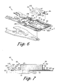
- FIG. 6 is an exploded view of a portion of a head gimbal assembly similar to FIG. 3 , however, according to another embodiment of an aspect of the present invention.
- FIG. 7 is an enlarged side view of the portion of the head gimbal assembly of FIG. 6 as seen along axis 7 — 7 , however, with the head gimbal assembly being assembled and electrical connections shown;
- FIG. 8 is an exploded view of a portion of a head gimbal assembly similar to FIG. 3 , however, according to another embodiment of an aspect of the present invention.
- FIG. 9 is an enlarged side view of the portion of the head gimbal assembly of FIG. 8 as send along axis 9 — 9 , however, with the head gimbal assembly being assembled and electrical connections shown.
- FIGS. 1–9 illustrate a disk drive including a head stack assembly in accordance with the aspects of the present invention.
- the disk drive 10 includes a head disk assembly (HDA) and a printed circuit board assembly (PCBA).
- the head disk assembly includes a disk drive base 12 and a cover 14 that collectively house at least one magnetic disk 16 .
- the disk 16 contains a plurality of tracks for storing data. The tracks are disposed upon opposing first and second disk surfaces 18 , 20 of the disk 16 that extend between an inner disk edge 22 (associated with the inner diameter) and an outer disk edge 24 (associated with the outer diameter) of the disk 16 .
- the head disk assembly further includes a spindle motor 26 for rotating the disk 16 .
- the head disk assembly further includes a head stack assembly 28 rotatably attached to the disk drive base 12 in operable communication with the disk 16 .
- the head stack assembly 28 includes a rotatable actuator 30 .
- the actuator 30 includes an actuator body 32 and actuator arms 34 , 36 that extend from the actuator body 32 .
- Distally attached to the actuator arms 34 , 36 are head gimbal assemblies 38 , 40 .
- the head gimbal assemblies 38 , 40 respectively support sliders 42 , 44 . It is contemplated that the number of actuator arms may vary depending upon the number of disks and disk surfaces utilized.
- the actuator body 32 includes a bore, and the actuator 30 further includes a pivot bearing cartridge 46 engaged within the bore for facilitating the actuator body 32 to rotate between limited positions about an axis of rotation 48 .
- the actuator 30 further includes a coil support 50 that extends from one side of the actuator body 32 opposite the actuator arms 34 , 36 .
- the coil support 50 is configured to support a coil 52 .
- a pair of magnetic elements 54 , 56 is supported by mounts 58 , 60 which are attached to the disk drive base 12 (magnetic element 56 is indicated by the dashed lead line and it is understood the magnetic element 56 is disposed underneath the mount 60 ).
- the magnetic elements 54 , 56 may be attached to the disk drive base 12 through other arrangements, such as the magnetic element 56 being directly mounted to the cover 12 which is mechanically engaged with the disk drive base 12 .
- the coil 52 interacts with the magnetic elements 54 , 56 to form a voice coil motor for controllably rotating the actuator 30 .
- FIG. 2 is an enlarged perspective view of a portion of the head gimbal assembly 40 of FIG. 1 .
- FIG. 3 is an enlarged exploded view of the portion of the head gimbal assembly 40 of FIG. 2 .
- FIG. 4 is an enlarged side view of the portion of the head gimbal assembly 40 of FIG. 2 as seen along axis 4 — 4 .
- FIG. 5 depicts the side view of the portion of the head gimbal assembly 40 of FIG. 4 with electrical connections shown.
- the head stack assembly 28 includes the actuator 30 including an actuator arm, such as actuator arm 36 .
- the head stack assembly 28 further includes a load beam 62 coupled to the actuator arm 36 .
- the load beam 62 is formed of an electrically conductive material.
- the head stack assembly 28 further includes a gimbal 64 coupled to the load beam 62 .
- the gimbal 64 is formed of an electrically conductive material.
- the head stack assembly 28 further includes a dielectric layer 66 disposed upon the gimbal 64 .
- the head stack assembly 28 further includes the slider 44 supported by the gimbal 64 .
- the head stack assembly 28 further includes slider conductive pads 68 disposed upon the dielectric layer 66 with the dielectric layer 66 interposed between the slider conductive pads 68 and the gimbal 64 .
- the slider conductive pads 68 are electrically connected to the slider 44 .
- the head stack assembly 28 further includes a ground conductive pad 70 disposed upon the dielectric layer 66 with the dielectric layer 66 interposed between the ground conductive pad 70 and the gimbal 64 .
- the ground conductive pad 70 is electrically connected to the slider 44 and the gimbal 64 for electrically grounding the slider 44 to the gimbal 64 .
- the head stack assembly 28 includes the actuator arm 36 and the attached head gimbal assembly 40 .
- the head gimbal assembly 40 includes the load beam 62 , the dielectric layer 64 , the slider 44 , the slider conductive pads 68 , and the ground conductive pad 70 as described above.
- the disk drive 10 including the disk drive base 12 and the head stack assembly 28 rotatably coupled to the disk drive base 12 .
- the load beam 62 and the gimbal 64 may be formed of an electrically conductive material such as stainless steel.
- the actuator arm 36 which is coupled to the disk drive base 12 and supports the load beam 62 may further be electrically conductive.
- electrical connection between the gimbal 64 and the slider 44 facilitates an electrical path to ground for the slider 44 .
- the gimbal 64 may include a gimbal body 72 which is supported by gimbal outriggers 74 in a hinge-like manner to allow the gimbal body 72 to move during “flight”.
- the dielectric layer may include dielectric layer pads 76 disposed upon the gimbal body 72 .
- the slider 44 may be supported by the gimbal 64 through attachment of the slider 44 to the gimbal body 72 .
- the slider 44 may be disposed upon the dielectric layer pads 76 .
- structural epoxy may be used for secure attachment of the slider 44 to the gimbal 64 while electrically insulating the slider 44 and the gimbal 64 .
- the slider 44 includes a transducer head 78 disposed within the slider 44 (as indicated in dashed line).
- the slider 44 may further include electrical connections 80 which are electrically connected to the transducer head 78 internally within the slider 44 .
- the slider 44 may include a ground connection 82 .
- the slider 44 may include a leading end 84 and an opposing trailing end 86 . In the embodiment shown, the electrical connections 80 and the ground connection 82 are disposed at the trailing end 86 of the slider 44 .
- the slider 44 may be electrically connected to the ground conductive pad 70 with the ground connection 82 electrically connected to the ground conductive pad 70 such as through ball bonding, solder ball bonding or wire bonding. As shown in FIG. 5 , a gold ball bond 88 may be utilized. Similarly, the slider 44 may be electrically connected to the slider conductive pads 68 with the electrical connections 80 electrically connected to the slider conductive pads 68 such as through ball bonding, solder ball bonding or wire bonding. Referring to FIG. 5 , gold ball bonds 90 may be utilized (as indicated in FIG. 5 in dashed lead line as the gold ball bond 90 is disposed behind the gold ball bond 88 in this view).
- the slider conductive pads 68 and the ground conductive pad 70 may be metal traces formed upon the dielectric layer 66 . These may be formed of copper and deposited and/or etched upon the dielectric layer 66 .
- the dielectric layer 66 may include a dielectric layer opening 92 formed through the dielectric layer 66 .
- the dielectric layer opening 92 may be circular, however other shapes are contemplated.
- the dielectric layer opening 92 is formed to expose the underlying gimbal 64 .
- a conductive ring 94 may extend from the ground conductive pad 70 and may be formed about the dielectric layer opening 92 .
- the ground conductive pad 70 may be electrically connected to the gimbal 64 through an electrically conductive material 96 disposed within the dielectric layer opening 66 .
- the conductive ring 94 and the dielectric layer opening 66 may form a cup-like boundary for containing the conductive material 96 .
- the conductive material 96 may take the form of a conductive epoxy (such as a silver epoxy).
- the dielectric layer opening 66 may be filled with conductive epoxy such as through a syringe or using a mask and screening technique. Once the conductive epoxy is cured, a voltage may be applied across the conductive epoxy in excess of the associated breakdown voltage for establishing a controlled impedance within the epoxy. Subsequently, the slider 44 may be attached to the gimbal 64 .
- the conductive material 96 may take other forms such as solder or even gold plating.
- FIG. 6 is an exploded view of a portion of the head gimbal assembly 40 similar to FIG. 3 however with the differences noted.
- FIG. 7 is an enlarged side view of the portion of the head gimbal assembly 40 of FIG. 6 as seen along axis 7 — 7 , however with the head gimbal assembly 40 being assembled and electrical connections shown.
- the slider 44 includes a ground conductive pad 98 similar to the ground conductive pad 70 , however the ground conductive pad 98 is disposed at the leading end 84 of the slider 44 .
- the slider 44 may include a ground connection 102 similar to the ground connection 82 , however the ground connection 102 is disposed at the leading end 84 of the slider 44 .
- a dielectric layer opening 104 may be disposed at the leading end 84 .
- the ground connection 102 is electrically connected to the ground conductive pad 98 with an electrically conductive material such as a gold ball bond 104 .
- a conductive ring 106 may extend from the ground conductive pad 98 .
- An electrically conductive material 108 such as silver epoxy, solder or gold plating, may be disposed within the conductive ring 106 and a dielectric layer opening 110 for electrically connecting the gimbal 64 to the ground conductive pad 98 .
- FIG. 8 is an exploded view of a portion of the head gimbal assembly 40 similar to FIG. 3 , however with the differences noted.
- FIG. 9 is an enlarged side view of the portion of the head gimbal assembly 40 of FIG. 8 as seen along axis 9 — 9 , however, with the head gimbal assembly 40 being assembled and electrical connections shown.
- the slider 44 is supported by the gimbal body 72 .
- the dielectric layer 112 is similar to the dielectric layer 66 , however, the dielectric layer 112 may extend along the gimbal body 72 from the trailing end 86 to the leading end 84 of where the slider 44 is supported by the gimbal body 72 .
- a ground conductive strip 114 is disposed upon the dielectric layer 112 .
- the ground conductive strip 114 includes a conductive ring 116 .
- the trailing end 86 of the slider 44 may be disposed generally adjacent the conductive ring 116 .
- the dielectric layer 112 may include a dielectric layer opening 118 .
- the conductive ring 116 may be disposed about the dielectric layer opening 118 . It is contemplated that the conductive ring 116 and the dielectric layer opening 118 may be disposed at other locations with respect to the slider 44 , such as adjacent the leading end 84 of the slider 44 for example.
- An electrically conductive material 120 such as silver epoxy, solder, or gold plating, may be disposed within the conductive ring 116 and the dielectric layer opening 118 for electrically connecting the gimbal 66 to the ground conductive strip 114 .
- the slider 44 may include a ground connection 122 disposed at the leading end 84 of the slider 44 .
- the ground conductive strip 114 may include a ground conductive pad 124 disposed at an opposing end of the ground conductive strip 114 from the conductive ring 116 .
- the ground connection 122 is electrically connected to the ground conductive pad 124 with an electrically conductive material such as a gold ball bond 126 .
- the slider 44 may be electrically grounded to the gimbal 64 through the gold ball bond 126 .
- the slider 44 is contemplated to be in contact with the ground conductive strip 114 .
- the slider 44 may be additionally electrically grounded to the gimbal 64 through such contact.
- the dielectric layer 112 may include slider support portions 128 .
- Slider support layers 130 may be disposed upon the slider support portions 128 .
- the slider support layers 130 may be formed of the same material used to form the ground conductive strip 114 and may be disposed upon the slider support portions 128 .
- the slider support layers 130 may be formed to the same height as the ground conductive strip 114 .
- the slider 44 may be disposed upon the slider support layers 130 and the ground conductive strip 114 .
- a structural epoxy may be used to attach the slider 44 and may reside upon the gimbal body 72 in those regions between the slider support layers 130 and the ground conductive strip 114 .
Abstract
Description
Claims (24)
Priority Applications (1)
| Application Number | Priority Date | Filing Date | Title |
|---|---|---|---|
| US10/386,259 US7006330B1 (en) | 2003-03-10 | 2003-03-10 | Head stack assembly including a ground conductive pad for grounding a slider to a gimbal |
Applications Claiming Priority (1)
| Application Number | Priority Date | Filing Date | Title |
|---|---|---|---|
| US10/386,259 US7006330B1 (en) | 2003-03-10 | 2003-03-10 | Head stack assembly including a ground conductive pad for grounding a slider to a gimbal |
Publications (1)
| Publication Number | Publication Date |
|---|---|
| US7006330B1 true US7006330B1 (en) | 2006-02-28 |
Family
ID=35922810
Family Applications (1)
| Application Number | Title | Priority Date | Filing Date |
|---|---|---|---|
| US10/386,259 Expired - Lifetime US7006330B1 (en) | 2003-03-10 | 2003-03-10 | Head stack assembly including a ground conductive pad for grounding a slider to a gimbal |
Country Status (1)
| Country | Link |
|---|---|
| US (1) | US7006330B1 (en) |
Cited By (63)
| Publication number | Priority date | Publication date | Assignee | Title |
|---|---|---|---|---|
| US20050068681A1 (en) * | 2003-09-27 | 2005-03-31 | Yao Ming Gao | Method and system of partial potting head slider to head suspension |
| US20060285252A1 (en) * | 2005-06-15 | 2006-12-21 | Shinobu Hagiya | Head assembly with reduced PSA tilt |
| US20060285250A1 (en) * | 2005-06-15 | 2006-12-21 | Shinobu Hagiya | Method for reducing PSA tilt through increased flexibility of contact pads |
| US20060285251A1 (en) * | 2005-06-15 | 2006-12-21 | Shinobu Hagiya | Method for reducing PSA tilt through standoff relocation |
| US20060285249A1 (en) * | 2005-06-15 | 2006-12-21 | Shinobu Hagiya | Method for reducing PSA tilt in Femto format sliders through increased adhesive area |
| US20070297094A1 (en) * | 2006-06-27 | 2007-12-27 | Seagate Technology Llc | Slider suspension assembly |
| US20080049361A1 (en) * | 2006-08-09 | 2008-02-28 | Fujitsu Limited | Head suspension and head gimbal assembly |
| US20080266714A1 (en) * | 2007-04-30 | 2008-10-30 | Sae Magnetics (H.K) Ltd. | Suspension and fabricating method thereof, head gimbal assembly and disk drive device |
| US20090086374A1 (en) * | 2007-10-01 | 2009-04-02 | Seagate Technology Llc | High density electrical interconnect assembly |
| US7532438B1 (en) * | 2005-05-16 | 2009-05-12 | Magnecomp Corporation | Wireless flexure with curved trace geometry against pitch and roll adjustment springback |
| US7567410B1 (en) | 2006-10-31 | 2009-07-28 | Western Digital Technologies, Inc. | Flexure including a heat sink and a dielectric layer under trace termination pads |
| US7593190B1 (en) | 2001-12-21 | 2009-09-22 | Western Digital (Fremont), Llc | Flexure design and assembly process for attachment of slider using solder and laser reflow |
| US7729089B1 (en) | 2006-10-13 | 2010-06-01 | Western Digital Technologies, Inc. | Head-gimbal assembly including a flexure tongue with stand-offs arranged to facilitate lateral light entry |
| US7995310B1 (en) | 2006-11-09 | 2011-08-09 | Western Digital Technologies, Inc. | Head-gimbal assembly including a flexure tongue with adhesive receptacles disposed adjacent to stand-offs |
| US8094413B1 (en) * | 2008-10-21 | 2012-01-10 | Hutchinson Technology Incorporated | Disk drive head suspension flexure with stacked traces having differing configurations on gimbal and beam regions |
| US8164858B1 (en) | 2009-11-04 | 2012-04-24 | Western Digital (Fremont), Llc | Read head having conductive filler in insulated hole through substrate |
| US8218268B1 (en) | 2009-05-27 | 2012-07-10 | Western Digital Technologies, Inc. | Head gimbal assembly having a load beam aperature over conductive heating pads that are offset from head bonding pads |
| US8730621B2 (en) * | 2012-07-09 | 2014-05-20 | Seagate Technology Llc | Solder ball bridge, and methods of making |
| US8792212B1 (en) | 2010-09-14 | 2014-07-29 | Western Digital (Fremont), Llc | Robust gimbal design for head gimbal assembly |
| US8792213B1 (en) * | 2013-02-20 | 2014-07-29 | Western Digital Technologies, Inc. | Tethered gimbal on suspension for improved flyability |
| US8797691B1 (en) | 2013-05-21 | 2014-08-05 | Western Digital Technologies, Inc. | Disk drive head suspension with a single piezoelectric element adhered to rotary-actuated and non-actuated portions of a structural layer of a tongue of a laminated flexure |
| US8929180B1 (en) | 2013-04-25 | 2015-01-06 | Western Digital Technologies, Inc. | Energy-assisted magnetic recording device having laser driving signal and magnetic write signal sharing same electrical conductor |
| US8934199B1 (en) | 2014-03-31 | 2015-01-13 | Western Digital Technologies, Inc. | Disk drive head suspension tail with bond pad edge alignment features |
| US8976491B1 (en) | 2013-05-09 | 2015-03-10 | Western Digital Technologies, Inc. | Disk drive head suspension distal non-op shock limiter with branched arms |
| US8982513B1 (en) | 2013-05-21 | 2015-03-17 | Western Digital Technologies, Inc. | Disk drive head suspension with dual piezoelectric elements adhered to rotary-actuated and non-actuated portions of a structural layer of a tongue of a laminated flexure |
| US8988830B1 (en) | 2013-05-13 | 2015-03-24 | Western Digital (Fremont), Llc | Air bearing design to mitigate lube waterfall effect |
| US9025283B1 (en) * | 2013-09-18 | 2015-05-05 | Western Digital Technologies, Inc. | Laminated suspension flexure with open polyimide base |
| US9042048B1 (en) | 2014-09-30 | 2015-05-26 | Western Digital (Fremont), Llc | Laser-ignited reactive HAMR bonding |
| US20150156892A1 (en) * | 2013-12-04 | 2015-06-04 | Nitto Denko Corporation | Producing method of suspension board with circuit |
| US9064513B1 (en) | 2014-03-07 | 2015-06-23 | Western Digital Technologies, Inc. | Disk drive suspension assembly with flexure having dual conductive layers with staggered traces |
| US9070387B1 (en) | 2013-08-23 | 2015-06-30 | Western Digital Technologies, Inc. | Integrated heat-assisted magnetic recording head/laser assembly |
| US9093102B1 (en) | 2013-03-12 | 2015-07-28 | Western Digital Technologies, Inc. | Systems and methods for tuning seed layer hardness in components of magnetic recording systems |
| US9099145B1 (en) | 2013-12-24 | 2015-08-04 | Western Digital (Fremont), Llc | High contrast alignment marker |
| US9105282B1 (en) | 2013-05-20 | 2015-08-11 | Western Digital Technologies, Inc. | Head gimbal assembly carrier with adjustable protective bar |
| US9135935B1 (en) | 2013-10-11 | 2015-09-15 | Western Digital Technologies, Inc. | Customized head gimbal assembly bonding skew angle for adjusting two-dimensional magnetic recording reader alignment |
| US9165579B1 (en) | 2014-09-26 | 2015-10-20 | Western Digital (Fremont), Llc | Air bearing area configuration for reducing flying height hump across a stroke |
| US9171562B1 (en) | 2015-03-19 | 2015-10-27 | Western Digital (Fremont), Llc | Patterned metal layer to control solder connection between laser and submount in a magnetic head |
| US9171561B1 (en) * | 2014-05-14 | 2015-10-27 | Seagate Technology Llc | Assemblies and methods for slider electrical connection containing through circuit electrical connections |
| US9183859B1 (en) | 2014-11-11 | 2015-11-10 | Western Digital (Fremont), Llc | HAMR writer pole length characterization |
| US9190090B1 (en) | 2014-12-24 | 2015-11-17 | Western Digital (Fremont), Llc | Multi step lube blocking air bearing area configuration |
| US9190089B1 (en) | 2014-12-24 | 2015-11-17 | Western Digital (Fremont), Llc | Air bearing area configuration for contaminating particle removal |
| US9202478B1 (en) | 2015-02-10 | 2015-12-01 | Western Digital (Fremont), Llc | Method and structure for soldering a laser submount to a mounting face of a slider |
| US9230580B1 (en) | 2010-06-30 | 2016-01-05 | Western Digital Technologies, Inc. | Suspension assembly having a microactuator grounded to a flexure |
| US9242340B1 (en) | 2013-03-12 | 2016-01-26 | Western Digital Technologies, Inc. | Method to stress relieve a magnetic recording head transducer utilizing ultrasonic cavitation |
| US9257138B1 (en) | 2014-10-28 | 2016-02-09 | Western Digital (Fremont), Llc | Slider assembly and method of manufacturing same |
| US9293157B1 (en) | 2012-06-28 | 2016-03-22 | Western Digital Technologies, Inc. | Automated active feedback slice and view milling of magnetic head cross-sections |
| US9315008B1 (en) | 2013-07-16 | 2016-04-19 | Western Digital Technologies, Inc. | Method and apparatus for aligning an illumination unit to a slider for a magnetic recording device |
| US9343084B2 (en) | 2012-03-14 | 2016-05-17 | Western Digital Technologies, Inc. | Systems and methods for correcting slider parallelism error using compensation lapping |
| US9361916B1 (en) | 2014-03-13 | 2016-06-07 | Western Digital (Fremont) | Electrical lapping guide for dimensional control of back side of heat assisted magnetic recording device |
| US9368139B1 (en) | 2015-03-20 | 2016-06-14 | Western Digital (Fremont), Llc | Slider back side etching to increase shear strength between suspension and slider |
| US9372078B1 (en) | 2014-06-20 | 2016-06-21 | Western Digital (Fremont), Llc | Detecting thickness variation and quantitative depth utilizing scanning electron microscopy with a surface profiler |
| US9387568B1 (en) | 2013-02-27 | 2016-07-12 | Western Digital Technologies, Inc. | Systems and methods for correcting fabrication error in magnetic recording heads using magnetic write width measurements |
| US9431044B1 (en) | 2014-05-07 | 2016-08-30 | Western Digital (Fremont), Llc | Slider having shock and particle resistance |
| US9431037B2 (en) | 2013-03-12 | 2016-08-30 | Western Digitatl (Fremont), LLC | Systems and methods for monitoring the power of a light source utilized in energy-assisted magnetic recording |
| US9583125B1 (en) * | 2009-12-16 | 2017-02-28 | Magnecomp Corporation | Low resistance interface metal for disk drive suspension component grounding |
| US9659587B1 (en) | 2015-11-06 | 2017-05-23 | Western Digital (Fremont), Llc | Magnetic head having a reader overcoat with DLC and a recessed writer overcoat without DLC |
| US9659589B2 (en) | 2015-09-29 | 2017-05-23 | Western Digital (Fremont), Llc | Free-standing reflector usable in heat assisted magnetic recording technology |
| US9685187B1 (en) | 2014-09-26 | 2017-06-20 | Western Digital (Fremont), Llc | Bonding tool and method for high accuracy chip-to-chip bonding |
| US9805748B1 (en) | 2014-06-24 | 2017-10-31 | Western Digital (Fremont), Llc | System and method for providing a protective layer having a graded intermediate layer |
| US9870788B2 (en) | 2014-01-08 | 2018-01-16 | Western Digital (Fremont), Llc | Method of adjusting tilt using magnetic erase width feedback |
| US9953666B2 (en) * | 2015-11-18 | 2018-04-24 | Seagate Technology Llc | Gimbal deflection inhibitor for head gimbal assembly |
| US20200098388A1 (en) * | 2018-09-24 | 2020-03-26 | Seagate Technology Llc | Slider with bondable surface opposite suspension trace |
| US10720179B1 (en) * | 2019-04-03 | 2020-07-21 | Western Digital Technologies, Inc. | Hard disk drive head assembly with tilt-preventing standoff formed on flexure cover beneath slider |
Citations (6)
| Publication number | Priority date | Publication date | Assignee | Title |
|---|---|---|---|---|
| US5657186A (en) * | 1994-09-01 | 1997-08-12 | Tdk Corporation | Device for supporting a magnetic head slider and magnetic head apparatus provided with the device including grounding electrical connection |
| US5864445A (en) * | 1994-04-15 | 1999-01-26 | Hutchinson Technology Incorporated | Hygrothermal load compensating structures in an integrated lead suspension |
| US5896248A (en) * | 1997-09-05 | 1999-04-20 | Read-Rite Corporation | Bond pads for metal welding of flexure to air bearing slider and grounding configuration thereof |
| US6515832B1 (en) * | 2000-04-19 | 2003-02-04 | Applied Kinetics, Inc. | Gimbal stiffness control for head suspension assemblies |
| US6621661B1 (en) * | 1998-11-13 | 2003-09-16 | Tdk Corporation | Write/read head supporting mechanism including a microactuator and a slider connected to a ground region of a suspension |
| US6700748B1 (en) * | 2000-04-28 | 2004-03-02 | International Business Machines Corporation | Methods for creating ground paths for ILS |
-
2003
- 2003-03-10 US US10/386,259 patent/US7006330B1/en not_active Expired - Lifetime
Patent Citations (6)
| Publication number | Priority date | Publication date | Assignee | Title |
|---|---|---|---|---|
| US5864445A (en) * | 1994-04-15 | 1999-01-26 | Hutchinson Technology Incorporated | Hygrothermal load compensating structures in an integrated lead suspension |
| US5657186A (en) * | 1994-09-01 | 1997-08-12 | Tdk Corporation | Device for supporting a magnetic head slider and magnetic head apparatus provided with the device including grounding electrical connection |
| US5896248A (en) * | 1997-09-05 | 1999-04-20 | Read-Rite Corporation | Bond pads for metal welding of flexure to air bearing slider and grounding configuration thereof |
| US6621661B1 (en) * | 1998-11-13 | 2003-09-16 | Tdk Corporation | Write/read head supporting mechanism including a microactuator and a slider connected to a ground region of a suspension |
| US6515832B1 (en) * | 2000-04-19 | 2003-02-04 | Applied Kinetics, Inc. | Gimbal stiffness control for head suspension assemblies |
| US6700748B1 (en) * | 2000-04-28 | 2004-03-02 | International Business Machines Corporation | Methods for creating ground paths for ILS |
Cited By (74)
| Publication number | Priority date | Publication date | Assignee | Title |
|---|---|---|---|---|
| US7593190B1 (en) | 2001-12-21 | 2009-09-22 | Western Digital (Fremont), Llc | Flexure design and assembly process for attachment of slider using solder and laser reflow |
| US20050068681A1 (en) * | 2003-09-27 | 2005-03-31 | Yao Ming Gao | Method and system of partial potting head slider to head suspension |
| US7532438B1 (en) * | 2005-05-16 | 2009-05-12 | Magnecomp Corporation | Wireless flexure with curved trace geometry against pitch and roll adjustment springback |
| US20060285249A1 (en) * | 2005-06-15 | 2006-12-21 | Shinobu Hagiya | Method for reducing PSA tilt in Femto format sliders through increased adhesive area |
| US20060285252A1 (en) * | 2005-06-15 | 2006-12-21 | Shinobu Hagiya | Head assembly with reduced PSA tilt |
| US20060285251A1 (en) * | 2005-06-15 | 2006-12-21 | Shinobu Hagiya | Method for reducing PSA tilt through standoff relocation |
| US20060285250A1 (en) * | 2005-06-15 | 2006-12-21 | Shinobu Hagiya | Method for reducing PSA tilt through increased flexibility of contact pads |
| US7545605B2 (en) * | 2005-06-15 | 2009-06-09 | Hitachi Global Storage Technologies Netherlands B.V. | Method for reducing PSA tilt through standoff relocation |
| US20070297094A1 (en) * | 2006-06-27 | 2007-12-27 | Seagate Technology Llc | Slider suspension assembly |
| US7852604B2 (en) * | 2006-06-27 | 2010-12-14 | Seagate Technology Llc | Slider suspension assembly including a flex circuit arm with a flex circuit tab attached to a gimbal spring arm |
| US20080049361A1 (en) * | 2006-08-09 | 2008-02-28 | Fujitsu Limited | Head suspension and head gimbal assembly |
| US7729089B1 (en) | 2006-10-13 | 2010-06-01 | Western Digital Technologies, Inc. | Head-gimbal assembly including a flexure tongue with stand-offs arranged to facilitate lateral light entry |
| US7567410B1 (en) | 2006-10-31 | 2009-07-28 | Western Digital Technologies, Inc. | Flexure including a heat sink and a dielectric layer under trace termination pads |
| US7995310B1 (en) | 2006-11-09 | 2011-08-09 | Western Digital Technologies, Inc. | Head-gimbal assembly including a flexure tongue with adhesive receptacles disposed adjacent to stand-offs |
| US20080266714A1 (en) * | 2007-04-30 | 2008-10-30 | Sae Magnetics (H.K) Ltd. | Suspension and fabricating method thereof, head gimbal assembly and disk drive device |
| US7924531B2 (en) * | 2007-04-30 | 2011-04-12 | Sae Magnetics (H. K) Ltd. | Suspension and fabricating method thereof, head gimbal assembly and disk drive device |
| US20090086374A1 (en) * | 2007-10-01 | 2009-04-02 | Seagate Technology Llc | High density electrical interconnect assembly |
| US7952833B2 (en) * | 2007-10-01 | 2011-05-31 | Seagate Technology Llc | High density electrical interconnect assembly |
| US8094413B1 (en) * | 2008-10-21 | 2012-01-10 | Hutchinson Technology Incorporated | Disk drive head suspension flexure with stacked traces having differing configurations on gimbal and beam regions |
| US8218268B1 (en) | 2009-05-27 | 2012-07-10 | Western Digital Technologies, Inc. | Head gimbal assembly having a load beam aperature over conductive heating pads that are offset from head bonding pads |
| US8325447B1 (en) | 2009-05-27 | 2012-12-04 | Western Digital Technologies, Inc. | Head gimbal assembly having a load beam aperature over conductive heating pads that are offset from head bonding pads |
| US8756795B1 (en) | 2009-11-04 | 2014-06-24 | Western Digital (Fremont), Llc | Method for manufacturing a read head having conductive filler in insulated hole through substrate |
| US8164858B1 (en) | 2009-11-04 | 2012-04-24 | Western Digital (Fremont), Llc | Read head having conductive filler in insulated hole through substrate |
| US9583125B1 (en) * | 2009-12-16 | 2017-02-28 | Magnecomp Corporation | Low resistance interface metal for disk drive suspension component grounding |
| US10876216B2 (en) | 2009-12-16 | 2020-12-29 | Magnecomp Corporation | Low resistance interface metal for disk drive suspension component grounding |
| US9230580B1 (en) | 2010-06-30 | 2016-01-05 | Western Digital Technologies, Inc. | Suspension assembly having a microactuator grounded to a flexure |
| US8792212B1 (en) | 2010-09-14 | 2014-07-29 | Western Digital (Fremont), Llc | Robust gimbal design for head gimbal assembly |
| US9343084B2 (en) | 2012-03-14 | 2016-05-17 | Western Digital Technologies, Inc. | Systems and methods for correcting slider parallelism error using compensation lapping |
| US9293157B1 (en) | 2012-06-28 | 2016-03-22 | Western Digital Technologies, Inc. | Automated active feedback slice and view milling of magnetic head cross-sections |
| US8730621B2 (en) * | 2012-07-09 | 2014-05-20 | Seagate Technology Llc | Solder ball bridge, and methods of making |
| US8792213B1 (en) * | 2013-02-20 | 2014-07-29 | Western Digital Technologies, Inc. | Tethered gimbal on suspension for improved flyability |
| US9387568B1 (en) | 2013-02-27 | 2016-07-12 | Western Digital Technologies, Inc. | Systems and methods for correcting fabrication error in magnetic recording heads using magnetic write width measurements |
| US9449631B2 (en) | 2013-03-12 | 2016-09-20 | Western Digital Technologies, Inc. | Slider for magnetic recording system |
| US9431037B2 (en) | 2013-03-12 | 2016-08-30 | Western Digitatl (Fremont), LLC | Systems and methods for monitoring the power of a light source utilized in energy-assisted magnetic recording |
| US9093102B1 (en) | 2013-03-12 | 2015-07-28 | Western Digital Technologies, Inc. | Systems and methods for tuning seed layer hardness in components of magnetic recording systems |
| US9242340B1 (en) | 2013-03-12 | 2016-01-26 | Western Digital Technologies, Inc. | Method to stress relieve a magnetic recording head transducer utilizing ultrasonic cavitation |
| US8929180B1 (en) | 2013-04-25 | 2015-01-06 | Western Digital Technologies, Inc. | Energy-assisted magnetic recording device having laser driving signal and magnetic write signal sharing same electrical conductor |
| US8976491B1 (en) | 2013-05-09 | 2015-03-10 | Western Digital Technologies, Inc. | Disk drive head suspension distal non-op shock limiter with branched arms |
| US8988830B1 (en) | 2013-05-13 | 2015-03-24 | Western Digital (Fremont), Llc | Air bearing design to mitigate lube waterfall effect |
| US9105282B1 (en) | 2013-05-20 | 2015-08-11 | Western Digital Technologies, Inc. | Head gimbal assembly carrier with adjustable protective bar |
| US8982513B1 (en) | 2013-05-21 | 2015-03-17 | Western Digital Technologies, Inc. | Disk drive head suspension with dual piezoelectric elements adhered to rotary-actuated and non-actuated portions of a structural layer of a tongue of a laminated flexure |
| US8797691B1 (en) | 2013-05-21 | 2014-08-05 | Western Digital Technologies, Inc. | Disk drive head suspension with a single piezoelectric element adhered to rotary-actuated and non-actuated portions of a structural layer of a tongue of a laminated flexure |
| US9315008B1 (en) | 2013-07-16 | 2016-04-19 | Western Digital Technologies, Inc. | Method and apparatus for aligning an illumination unit to a slider for a magnetic recording device |
| US9070387B1 (en) | 2013-08-23 | 2015-06-30 | Western Digital Technologies, Inc. | Integrated heat-assisted magnetic recording head/laser assembly |
| US9025283B1 (en) * | 2013-09-18 | 2015-05-05 | Western Digital Technologies, Inc. | Laminated suspension flexure with open polyimide base |
| US9135935B1 (en) | 2013-10-11 | 2015-09-15 | Western Digital Technologies, Inc. | Customized head gimbal assembly bonding skew angle for adjusting two-dimensional magnetic recording reader alignment |
| US9693467B2 (en) * | 2013-12-04 | 2017-06-27 | Nitto Denko Corporation | Producing method of suspension board with circuit |
| US20150156892A1 (en) * | 2013-12-04 | 2015-06-04 | Nitto Denko Corporation | Producing method of suspension board with circuit |
| US9099145B1 (en) | 2013-12-24 | 2015-08-04 | Western Digital (Fremont), Llc | High contrast alignment marker |
| US9870788B2 (en) | 2014-01-08 | 2018-01-16 | Western Digital (Fremont), Llc | Method of adjusting tilt using magnetic erase width feedback |
| US9064513B1 (en) | 2014-03-07 | 2015-06-23 | Western Digital Technologies, Inc. | Disk drive suspension assembly with flexure having dual conductive layers with staggered traces |
| US9361916B1 (en) | 2014-03-13 | 2016-06-07 | Western Digital (Fremont) | Electrical lapping guide for dimensional control of back side of heat assisted magnetic recording device |
| US8934199B1 (en) | 2014-03-31 | 2015-01-13 | Western Digital Technologies, Inc. | Disk drive head suspension tail with bond pad edge alignment features |
| US9431044B1 (en) | 2014-05-07 | 2016-08-30 | Western Digital (Fremont), Llc | Slider having shock and particle resistance |
| US9171561B1 (en) * | 2014-05-14 | 2015-10-27 | Seagate Technology Llc | Assemblies and methods for slider electrical connection containing through circuit electrical connections |
| US9372078B1 (en) | 2014-06-20 | 2016-06-21 | Western Digital (Fremont), Llc | Detecting thickness variation and quantitative depth utilizing scanning electron microscopy with a surface profiler |
| US9805748B1 (en) | 2014-06-24 | 2017-10-31 | Western Digital (Fremont), Llc | System and method for providing a protective layer having a graded intermediate layer |
| US9165579B1 (en) | 2014-09-26 | 2015-10-20 | Western Digital (Fremont), Llc | Air bearing area configuration for reducing flying height hump across a stroke |
| US9685187B1 (en) | 2014-09-26 | 2017-06-20 | Western Digital (Fremont), Llc | Bonding tool and method for high accuracy chip-to-chip bonding |
| US9042048B1 (en) | 2014-09-30 | 2015-05-26 | Western Digital (Fremont), Llc | Laser-ignited reactive HAMR bonding |
| US9257138B1 (en) | 2014-10-28 | 2016-02-09 | Western Digital (Fremont), Llc | Slider assembly and method of manufacturing same |
| US9183859B1 (en) | 2014-11-11 | 2015-11-10 | Western Digital (Fremont), Llc | HAMR writer pole length characterization |
| US9190090B1 (en) | 2014-12-24 | 2015-11-17 | Western Digital (Fremont), Llc | Multi step lube blocking air bearing area configuration |
| US9190089B1 (en) | 2014-12-24 | 2015-11-17 | Western Digital (Fremont), Llc | Air bearing area configuration for contaminating particle removal |
| US9202478B1 (en) | 2015-02-10 | 2015-12-01 | Western Digital (Fremont), Llc | Method and structure for soldering a laser submount to a mounting face of a slider |
| US9171562B1 (en) | 2015-03-19 | 2015-10-27 | Western Digital (Fremont), Llc | Patterned metal layer to control solder connection between laser and submount in a magnetic head |
| US9368139B1 (en) | 2015-03-20 | 2016-06-14 | Western Digital (Fremont), Llc | Slider back side etching to increase shear strength between suspension and slider |
| US9659589B2 (en) | 2015-09-29 | 2017-05-23 | Western Digital (Fremont), Llc | Free-standing reflector usable in heat assisted magnetic recording technology |
| US9659587B1 (en) | 2015-11-06 | 2017-05-23 | Western Digital (Fremont), Llc | Magnetic head having a reader overcoat with DLC and a recessed writer overcoat without DLC |
| US9953666B2 (en) * | 2015-11-18 | 2018-04-24 | Seagate Technology Llc | Gimbal deflection inhibitor for head gimbal assembly |
| US10242701B2 (en) | 2015-11-18 | 2019-03-26 | Seagate Technology Llc | Gimbal detection inhibitor for head gimbal assembly |
| US20200098388A1 (en) * | 2018-09-24 | 2020-03-26 | Seagate Technology Llc | Slider with bondable surface opposite suspension trace |
| US10643645B2 (en) * | 2018-09-24 | 2020-05-05 | Seagate Technology Llc | Slider with bondable surface opposite suspension trace |
| US10720179B1 (en) * | 2019-04-03 | 2020-07-21 | Western Digital Technologies, Inc. | Hard disk drive head assembly with tilt-preventing standoff formed on flexure cover beneath slider |
Similar Documents
| Publication | Publication Date | Title |
|---|---|---|
| US7006330B1 (en) | Head stack assembly including a ground conductive pad for grounding a slider to a gimbal | |
| US7099117B1 (en) | Head stack assembly including a trace suspension assembly backing layer and a ground trace for grounding a slider | |
| US7027264B1 (en) | Slider with a slider ground pad electrically connected to write head poles and read head shields | |
| US7006331B1 (en) | Head gimbal assembly including a trace suspension assembly backing layer with a conductive layer formed upon a gimbal having a lower oxidation rate | |
| US7595963B1 (en) | Head gimbal assembly including a flexure with a first conductive trace disposed between a slider and a dielectric layer | |
| US9472218B2 (en) | Suspension assembly having a microactuator electrically connected to a gold coating on a stainless steel surface | |
| US6522504B1 (en) | Head stack assembly and disk drive using a reversed direction head gimbal assembly | |
| US7280319B1 (en) | Suspension assembly with piezoelectric microactuators electrically connected to a folded flex circuit segment | |
| CN102314888B (en) | There is the suspension module of the micro-actuator being grounding to flex member | |
| US8045295B2 (en) | Method and apparatus for providing an additional ground pad and electrical connection for grounding a magnetic recording head | |
| US8339748B2 (en) | Suspension assembly having a microactuator bonded to a flexure | |
| US7403357B1 (en) | Disk drive flexure assembly with a plurality of support bond pad apertures with a bond pad disposed over a bond pad support and part of each support bond pad aperture | |
| US8605389B1 (en) | Head gimbal assembly including a conductive trace disposed upon a continuous dielectric layer segment without overlying a gimbal arm | |
| US6967800B1 (en) | Disk drive suspension assembly including a base plate with mass reduction openings at distal corners | |
| US5754369A (en) | Head suspension with self-shielding integrated conductor trace array | |
| US6704165B2 (en) | Attachment of a head-gimbal assembly to a printed circuit board actuator arm using Z-axis conductive adhesive film | |
| US7110222B2 (en) | System and apparatus for assembling hard disk drive integrated lead suspensions to arm electronics cables via additional degrees of freedom at the tail termination and impedance grooming thereof | |
| US7113372B2 (en) | HGA plateau gimbal design | |
| JP3342638B2 (en) | Head gimbal assembly and information storage system | |
| US20030128474A1 (en) | Low electrical impedance slider grounding | |
| JP2012123896A (en) | Integrated lead suspension (ils) for use with dual stage actuator (dsa) | |
| JP2000215428A (en) | Head slider support and head device and their manufacturing method | |
| US20110090601A1 (en) | Suspension with flexure tail and manufacturing method thereof, head stack assembly and disk drive unit with the same | |
| US20060087768A1 (en) | Method and apparatus for electrically coupling a slider to a wireless suspension substrate | |
| US6233117B1 (en) | Electrically conductive path between head assembly and gimbal assembly in magnetic disc drive |
Legal Events
| Date | Code | Title | Description |
|---|---|---|---|
| AS | Assignment |
Owner name: WESTERN DIGITAL TECHNOLOGIES, INC., CALIFORNIA Free format text: ASSIGNMENT OF ASSIGNORS INTEREST;ASSIGNORS:SUBRAHMANYAM, JAI N.;PALMER, DARRELL D.;REEL/FRAME:014202/0427 Effective date: 20030617 |
|
| AS | Assignment |
Owner name: GENERAL ELECTRIC CAPITAL CORPORATION, AS AGENT, CA Free format text: SECURITY INTEREST;ASSIGNORS:WESTERN DIGITAL TECHNOLOGIES, INC.;WESTERN DIGITAL (FREMONT), INC.;REEL/FRAME:014830/0957 Effective date: 20030919 |
|
| STCF | Information on status: patent grant |
Free format text: PATENTED CASE |
|
| AS | Assignment |
Owner name: WESTERN DIGITAL TECHNOLOGIES, INC., CALIFORNIA Free format text: RELEASE BY SECURED PARTY;ASSIGNOR:GENERAL ELECTRIC CAPITAL CORPORATION, AS AGENT;REEL/FRAME:020599/0489 Effective date: 20070809 Owner name: WESTERN DIGITAL (FREMONT), INC., CALIFORNIA Free format text: RELEASE BY SECURED PARTY;ASSIGNOR:GENERAL ELECTRIC CAPITAL CORPORATION, AS AGENT;REEL/FRAME:020599/0489 Effective date: 20070809 |
|
| FPAY | Fee payment |
Year of fee payment: 4 |
|
| FPAY | Fee payment |
Year of fee payment: 8 |
|
| AS | Assignment |
Owner name: U.S. BANK NATIONAL ASSOCIATION, AS COLLATERAL AGENT, CALIFORNIA Free format text: SECURITY AGREEMENT;ASSIGNOR:WESTERN DIGITAL TECHNOLOGIES, INC.;REEL/FRAME:038744/0281 Effective date: 20160512 Owner name: JPMORGAN CHASE BANK, N.A., AS COLLATERAL AGENT, ILLINOIS Free format text: SECURITY AGREEMENT;ASSIGNOR:WESTERN DIGITAL TECHNOLOGIES, INC.;REEL/FRAME:038744/0481 Effective date: 20160512 Owner name: JPMORGAN CHASE BANK, N.A., AS COLLATERAL AGENT, ILLINOIS Free format text: SECURITY AGREEMENT;ASSIGNOR:WESTERN DIGITAL TECHNOLOGIES, INC.;REEL/FRAME:038722/0229 Effective date: 20160512 Owner name: JPMORGAN CHASE BANK, N.A., AS COLLATERAL AGENT, IL Free format text: SECURITY AGREEMENT;ASSIGNOR:WESTERN DIGITAL TECHNOLOGIES, INC.;REEL/FRAME:038722/0229 Effective date: 20160512 Owner name: JPMORGAN CHASE BANK, N.A., AS COLLATERAL AGENT, IL Free format text: SECURITY AGREEMENT;ASSIGNOR:WESTERN DIGITAL TECHNOLOGIES, INC.;REEL/FRAME:038744/0481 Effective date: 20160512 Owner name: U.S. BANK NATIONAL ASSOCIATION, AS COLLATERAL AGEN Free format text: SECURITY AGREEMENT;ASSIGNOR:WESTERN DIGITAL TECHNOLOGIES, INC.;REEL/FRAME:038744/0281 Effective date: 20160512 |
|
| FPAY | Fee payment |
Year of fee payment: 12 |
|
| AS | Assignment |
Owner name: WESTERN DIGITAL TECHNOLOGIES, INC., CALIFORNIA Free format text: RELEASE BY SECURED PARTY;ASSIGNOR:U.S. BANK NATIONAL ASSOCIATION, AS COLLATERAL AGENT;REEL/FRAME:045501/0714 Effective date: 20180227 |
|
| AS | Assignment |
Owner name: WESTERN DIGITAL TECHNOLOGIES, INC., CALIFORNIA Free format text: RELEASE OF SECURITY INTEREST AT REEL 038744 FRAME 0481;ASSIGNOR:JPMORGAN CHASE BANK, N.A.;REEL/FRAME:058982/0556 Effective date: 20220203 |
|
| AS | Assignment |
Owner name: JPMORGAN CHASE BANK, N.A., ILLINOIS Free format text: PATENT COLLATERAL AGREEMENT - A&R LOAN AGREEMENT;ASSIGNOR:WESTERN DIGITAL TECHNOLOGIES, INC.;REEL/FRAME:064715/0001 Effective date: 20230818 Owner name: JPMORGAN CHASE BANK, N.A., ILLINOIS Free format text: PATENT COLLATERAL AGREEMENT - DDTL LOAN AGREEMENT;ASSIGNOR:WESTERN DIGITAL TECHNOLOGIES, INC.;REEL/FRAME:067045/0156 Effective date: 20230818 |