US7007694B2 - Nasal cannula - Google Patents
Nasal cannula Download PDFInfo
- Publication number
- US7007694B2 US7007694B2 US11/053,587 US5358705A US7007694B2 US 7007694 B2 US7007694 B2 US 7007694B2 US 5358705 A US5358705 A US 5358705A US 7007694 B2 US7007694 B2 US 7007694B2
- Authority
- US
- United States
- Prior art keywords
- tubing
- nasal
- cannula
- filter
- patient
- Prior art date
- Legal status (The legal status is an assumption and is not a legal conclusion. Google has not performed a legal analysis and makes no representation as to the accuracy of the status listed.)
- Active
Links
Images


Classifications
-
- A—HUMAN NECESSITIES
- A61—MEDICAL OR VETERINARY SCIENCE; HYGIENE
- A61M—DEVICES FOR INTRODUCING MEDIA INTO, OR ONTO, THE BODY; DEVICES FOR TRANSDUCING BODY MEDIA OR FOR TAKING MEDIA FROM THE BODY; DEVICES FOR PRODUCING OR ENDING SLEEP OR STUPOR
- A61M16/00—Devices for influencing the respiratory system of patients by gas treatment, e.g. mouth-to-mouth respiration; Tracheal tubes
- A61M16/06—Respiratory or anaesthetic masks
- A61M16/0666—Nasal cannulas or tubing
-
- A—HUMAN NECESSITIES
- A61—MEDICAL OR VETERINARY SCIENCE; HYGIENE
- A61M—DEVICES FOR INTRODUCING MEDIA INTO, OR ONTO, THE BODY; DEVICES FOR TRANSDUCING BODY MEDIA OR FOR TAKING MEDIA FROM THE BODY; DEVICES FOR PRODUCING OR ENDING SLEEP OR STUPOR
- A61M16/00—Devices for influencing the respiratory system of patients by gas treatment, e.g. mouth-to-mouth respiration; Tracheal tubes
- A61M16/10—Preparation of respiratory gases or vapours
- A61M16/105—Filters
- A61M16/1055—Filters bacterial
-
- A—HUMAN NECESSITIES
- A61—MEDICAL OR VETERINARY SCIENCE; HYGIENE
- A61M—DEVICES FOR INTRODUCING MEDIA INTO, OR ONTO, THE BODY; DEVICES FOR TRANSDUCING BODY MEDIA OR FOR TAKING MEDIA FROM THE BODY; DEVICES FOR PRODUCING OR ENDING SLEEP OR STUPOR
- A61M2210/00—Anatomical parts of the body
- A61M2210/06—Head
- A61M2210/0625—Mouth
Definitions
- Embodiments of the invention are directed to nasal and oro-nasal cannulas.
- a “single lumen” cannula provides a single fluid connection from a patient's nares to a respiratory device, such as an oxygen concentrator. Each piece of tubing extending over a patient's ears fluidly merge, such as under the patient's chin or behind the patient's head.
- a single lumen cannula only a single flow path exists between the patient and a respiratory device in spite of the fact that the cannula may have two nasal prongs, one for each naris.
- “Dual lumen,” “bifurcated” or divided nasal cannulas have to two independent flow paths, one each for each naris of a patient. Much like the single lumen cannula, a dual lumen cannula may have two nasal prongs. In a dual lumen cannula, however, the flow pathways to each naris may be separated by a barrier or bifurcation.
- Nasal cannulas of any variety are a very personal item, and not generally shared with others. In fact, sharing of a nasal cannula could result in a transmission of various ailments from person to person, such as tuberculosis.
- the respiratory devices to which the cannulas connect may also pose a risk of transmitting various ailments.
- a conserver device which senses inhalation of a patient and delivers a bolus of therapeutic gas, may be transferred from patient to patient. Even if a new nasal cannula is used for each patient, the conserver may carry viruses and/or bacteria from one patient to the next. This risk is minimal for respiratory devices where patient airflow does not flow through the device.
- the respiratory devices are used by multiple patients, they run the risk of becoming a vehicle for the transfer of various viruses and/or bacteria.
- many of the devices developed by at least some of the inventors of the present specification need to measure airflow and/or pressure of each breathing orifice individually, but these measurements are difficult using related art single lumen and/or dual lumen nasal cannulas, especially with regard to oro-nasal measurements.
- Some illustrative embodiments are a cannula comprising a first nasal tube having a device end and an aperture end (wherein the cannula is configured to place the aperture end in fluid communication with the first naris of a patient), a second nasal tubing having a device end and an aperture end (wherein the cannula is configured to place the aperture end of the second nasal tubing in fluid communication with a second naris of the patient), and an oral tubing having a device end and an aperture end, and the oral tubing mechanically coupled to at least one of the first or second nasal tubing (wherein the cannula is configured to place the aperture end of the oral tubing in fluid communication with the mouth of a patient).
- the first nasal tubing, the second nasal tubing and the oral tubing are fluidly independent between their aperture ends and their device ends.
- illustrative embodiments may be a cannula comprising a first nasal tubing (wherein the cannula is configured to place a patient end of the first nasal tubing in fluid communication with a first naris of a patient), a first inline filter within the flow path of the first nasal tubing, a second nasal tubing mechanically coupled to the first nasal tubing (wherein the cannula is configured to place a patient end of the second nasal tubing in fluid communication with the second naris of the patient), and a second inline filter within the flow path of the second nasal tubing.
- the first and second nasal tubings are fluidly independent.
- Yet further illustrative embodiments may be a respiratory air filter comprising a first flow pathway comprising an inlet port and an outlet port fluidly coupled to a first cavity (the first cavity defined, at least in part, by an outer housing), a second flow pathway comprising an inlet port and an outlet port fluidly coupled to a second cavity (the second cavity defined, at least in part, by an outer housing), a first filter within the first cavity, and a second filter within the second cavity. At least a portion of the outer housing defining the first cavity is mechanically coupled to the outer housing defining the second cavity.
- FIG. 1 illustrates a three tube cannula assembly in accordance with embodiments of the invention
- FIG. 2 illustrates alternative embodiments of a three tube cannula assembly in accordance with embodiments of the invention
- FIG. 3 illustrates alternative embodiments comprising a dual lumen cannula in accordance with embodiments of the invention
- FIG. 4 illustrates non-integral filter assemblies in accordance with embodiments of the invention
- FIG. 5 illustrates non-integral filter assemblies in accordance with alternative embodiments of the invention
- FIG. 6 illustrates an integral filter assembly in accordance with embodiments of the invention
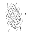
- FIG. 7 illustrates, in greater detail, an integral filter assembly in accordance with embodiments of the invention
- FIG. 8 shows an elevational cross-sectional view of a filter assembly taken along line 8 — 8 of FIG. 7 ;
- FIG. 9 illustrates, in greater detail, the relationship of the nasal prongs and oral interface in accordance with at least embodiments of the invention.
- the terms “including” and “comprising” are used in an open-ended fashion, and thus should be interpreted to mean “including, but not limited to . . . ”.
- the term “couple” or “couples” is intended to mean either an indirect or direct connection. Thus, if a first device couples to a second device, that connection may be through a direct connection, or through an indirect connection via other devices and connections.
- FIG. 1 illustrates a three tube cannula assembly 10 comprising a first nasal tubing assembly 12 , a second nasal tubing assembly 14 , and an oral tubing assembly 16 .
- First nasal tubing assembly 12 comprises a tube 18 having a nasal interface or prong 20 on the aperture or patient end, and a connector 22 on a device end.
- Second nasal tubing assembly 14 comprises a tube 24 having a nasal prong 26 on the aperture or patient end, and a connector 28 on a device end.
- Oral tubing assembly 16 comprises tube 30 having an oral interface 32 on the aperture or patient end, and a connector 34 on the device end.
- Each tubing assembly 12 , 14 and 16 provides an independent and isolated fluid flow pathway from their patient interfaces (nasal prongs 20 , 26 and oral interface 32 ) to their connectors 22 , 28 and 34 through their respective tubing, which tubing may have an inner diameter approximately equal to 1/16 inch in some embodiments.
- nasal tubing assemblies 12 and 14 are mechanically connected near the prongs 20 and 26 , although they are not in fluid communication with each other.
- a permanent barrier or bifurcation 36 fluidly isolates the tubings 18 and 24 .
- oral tubing 30 runs parallel to nasal tubing 24 .
- the oral tubing is mechanically coupled to the illustrative nasal tubing 24 , such as by a bonding agent, or mechanical device or devices that hold the two tubings together.
- FIG. 1 shows the oral tubing 30 hooked behind the patient's left ear, through oral tubing 30 may equivalently run parallel to the nasal tubing 18 over the patient's right ear.
- FIG. 1 shows the nasal tubings 18 and 24 , along with the oral tubing 30 , converging below the patient's chin, the convergence point may be equivalently behind the patient's head (not specifically shown).
- the illustrative three tube cannula assembly 10 of FIG. 1 may be used, for example, in individually measuring attributes of airflow through each of a patient's breathing orifices, such as described in co-pending U.S. patent application Ser. No. 10/616,042, titled “Method and System for Measuring Air Flow of Nares,” filed Jul. 9, 2003 and incorporated by reference herein as if reproduced in full below.
- the illustrative three tube cannula assembly 10 provides a convenient mechanism for fluidly coupling the various orifices to the illustrative respiratory devices by way of a single, integral assembly 10 not heretofore seen or contemplated in the related art.
- FIG. 2 illustrates alternative embodiments of the three tube cannula assembly 10 that comprises an integral filter assembly 50 fluidly coupled within each of the flow pathways of the three tube cannula assembly 10 .
- the integral filter assembly 50 comprises a first filter assembly 52 , a second filter assembly 54 and a third filter assembly 56 .
- Each of the filter assemblies may comprise a microbial and/or hydrophobic filter element. Illustrative embodiments of an integral filter assembly 50 are discussed more fully with respect to FIG. 7 .
- FIG. 1 illustrates alternative embodiments of the three tube cannula assembly 10 that comprises an integral filter assembly 50 fluidly coupled within each of the flow pathways of the three tube cannula assembly 10 .
- the integral filter assembly 50 comprises a first filter assembly 52 , a second filter assembly 54 and a third filter assembly 56 .
- Each of the filter assemblies may comprise a microbial and/or hydrophobic filter element. Illustrative embodiments of an integral filter assembly 50 are discussed more fully with respect to FIG. 7 .
- each tube of the three tube cannula assembly 10 comprises its own filter inline with the fluid flow pathway, fluidly independent from the fluid flow pathways of the other tubes and other filters.
- Devices that use mass flow sensors are protected from becoming carriers of viruses and/or bacteria, as the viruses and/or bacteria are kept out of the devices by way of the filters.
- the microbial filter ensures that these microbes are not inhaled by the patient.
- FIG. 3 illustrates alternative embodiments of the invention comprising a dual lumen or bifurcated cannula assembly with an integral filter assembly 62 coupled within the fluid flow pathway.
- the illustrative bifurcated nasal cannula comprises a first tubing 64 fluidly coupled within the patient's right naris by way of a nasal prong 66 .
- the bifurcated nasal cannula 60 comprises a second tubing 68 coupled to the patient's left naris by way of a second nasal prong 70 .
- the tubing 64 and nasal prong 66 are in fluid communication with the connector 72 through a first filter assembly 74 of the illustrative integral filter assembly 62 .
- the second tubing 68 and corresponding nasal prong 70 are in fluid communication with the connector 76 by way of a second filter assembly 78 , being part of the integral filter assembly 62 .
- Each of the filter assemblies 74 , 78 may comprise a microbial and/or hydrophobic filter element.
- FIG. 4 illustrates alternative embodiments of the invention comprising non-integral filter assemblies.
- FIG. 4 illustrates, for the case of a three tube cannula assembly, a first filter assembly 90 , a second filter assembly 92 , and a third filter assembly 94 .
- FIG. 4 thus illustrates that the filters need not necessarily be an integral unit with fluidly divided cavities containing microbial and/or hydrophobic filter elements.
- FIG. 4 illustrates that the filters need not necessarily be an integral unit with fluidly divided cavities containing microbial and/or hydrophobic filter elements.
- each of the filter assemblies 90 , 92 and 94 are shown to be between the patient end of the nasal cannula and the device end.
- the non-integral filter assemblies 90 , 92 and 94 may be proximate to connectors, generically labeled 96 .
- each of the filter assemblies 90 , 92 and 94 may be integral with their respective connectors, and thus at least in part form the device end of the cannula.
- FIG. 6 illustrates yet further alternative embodiments wherein an integral filter assembly 50 may itself perform a dual function of filtering the air and being a connector by which the nasal cannula couples to respiratory devices.
- FIGS. 4 , 5 and 6 may plug directly into an illustrative device, such as a device to determine nasal resistance, without the need of further tubing and/or connectors.
- FIGS. 4 , 5 and 6 show three independent flow pathways, and thus are applicable for a three tube cannula assembly 10 , the descriptions are equally applicable for a bifurcated nasal cannula, such as illustrative bifurcated cannula 60 of FIG. 3 .
- the integral filter assembly 50 comprises three fluidly isolated cavities 100 , 102 and 104 defined, respectively, by three outer housings 101 , 103 and 105 .
- Each cavity fluidly couples to an inlet port, which couples to the patient, and an outlet port, which couples to a sensing device.
- an inlet port which couples to the patient
- an outlet port which couples to a sensing device.
- Cavity 100 is fluidly coupled to an inlet port 106 and an outlet port 108 .
- cavity 102 is fluidly coupled to an inlet port 110 and an outlet port 112 .
- cavity 104 is fluidly coupled to inlet an port 114 and an outlet port 116 .
- the inlet ports 106 , 110 and 114 are coplanar.
- the outlet ports 108 , 112 and 116 are coplanar, and the planes defined by the inlet ports and the outlet ports are substantially parallel.
- FIG. 8 illustrates a cross-sectional elevational view of a cavity and corresponding inlet and outlet ports taken along line 8 — 8 of FIG. 7 .
- FIG. 8 is discussed in relation to cavity 100 defined by outer housing 101 ; however, it will be understood that the discussion is equally applicable to the flow pathways through cavities 102 and 104 .
- cavity 100 fluidly couples to inlet port 106 and outlet port 108 .
- the cavity 100 is bisected or divided by a hydrophobic and/or microbial filter 120 , and thus the airflow through inlet port 106 and outlet port 108 (in either direction) flows through the filter 120 .
- airflow may move through the filter assembly in the direction indicated by arrow 130 .
- the filter 120 may be any suitable material for filtering moisture, bacteria and/or viruses, such as filter material provided by Whatman International, Ltd. of Maidstone, England or Porous Media of St. Paul, Minn.
- the filter material 120 may be held in place by internal members 122 and 124 , each having at least one aperture 126 and 128 respectively therethrough. The apertures allow airflow through the filter.
- the plane defined by the filter material 120 may be substantially parallel to a plane defined by the inlet ports.
- the filter material 120 may be substantially parallel to a plane defined by the outlet ports 108 . While aligning the filter material 120 in a plane substantially parallel to a plane defined by the inlet ports and outlet ports is not strictly required to practice embodiments of the invention, such an alignment reduces the thickness “T” ( FIG. 8 ) of the overall assembly. In some embodiments, the thickness may be 1 ⁇ 2 inch or less. The thickness may be reduced further as the outside diameters (OD) of the inlet port and outlet port 106 and 108 respectively reduces from the preferred 1 ⁇ 4 inch.
- the relatively small thickness “T” provides for an unobtrusive presence of the filter assembly, such by affixing the filter assembly to the garment on the patient's chest.
- FIG. 9 illustrates in greater detail the relationship of the nasal prongs and oral interface in accordance with at least some embodiments of the invention.
- FIG. 9 shows right nasal prong 20 , left nasal prong 26 and oral interface 32 .
- the right nasal prong 20 is placed in fluid communication with patient's right naris
- the left nasal prong 26 is placed in fluid communication with the patient's left naris
- the oral interface 32 is placed in fluid communication with the patient's mouth.
- the prongs 20 , 26 , as well as the oral interface 32 have a length at least as long as may be needed for any patient, and the prongs and interface may then be trimmed to precisely fit each particular patient.
- the apertures of the nasal prongs are placed just below the nasal openings.
- the nasal prongs 20 and 26 may be removed completely and/or not provided, and in these embodiments an aperture into the respective tubings may be the mechanism by which the patient is fluidly coupled to the independent flow paths of the cannula.
- a non-bifurcated oral tube may extend over each ear, merging below the patient's chin or behind the patient's head.
Abstract
Description
Claims (12)
Priority Applications (5)
| Application Number | Priority Date | Filing Date | Title |
|---|---|---|---|
| US11/053,587 US7007694B2 (en) | 2004-05-21 | 2005-02-08 | Nasal cannula |
| EP05748754A EP1755717A4 (en) | 2004-05-21 | 2005-05-16 | Nasal cannula |
| JP2007527326A JP2008500132A (en) | 2004-05-21 | 2005-05-16 | Nasal cannula |
| AU2005247389A AU2005247389A1 (en) | 2004-05-21 | 2005-05-16 | Nasal cannula |
| PCT/US2005/016936 WO2005115519A2 (en) | 2004-05-21 | 2005-05-16 | Nasal cannula |
Applications Claiming Priority (2)
| Application Number | Priority Date | Filing Date | Title |
|---|---|---|---|
| US57356604P | 2004-05-21 | 2004-05-21 | |
| US11/053,587 US7007694B2 (en) | 2004-05-21 | 2005-02-08 | Nasal cannula |
Publications (2)
| Publication Number | Publication Date |
|---|---|
| US20050257794A1 US20050257794A1 (en) | 2005-11-24 |
| US7007694B2 true US7007694B2 (en) | 2006-03-07 |
Family
ID=35374006
Family Applications (1)
| Application Number | Title | Priority Date | Filing Date |
|---|---|---|---|
| US11/053,587 Active US7007694B2 (en) | 2004-05-21 | 2005-02-08 | Nasal cannula |
Country Status (5)
| Country | Link |
|---|---|
| US (1) | US7007694B2 (en) |
| EP (1) | EP1755717A4 (en) |
| JP (1) | JP2008500132A (en) |
| AU (1) | AU2005247389A1 (en) |
| WO (1) | WO2005115519A2 (en) |
Cited By (62)
| Publication number | Priority date | Publication date | Assignee | Title |
|---|---|---|---|---|
| US20050284484A1 (en) * | 1997-04-29 | 2005-12-29 | Curti James N | Nasal cannula for acquiring breathing information |
| US20060042632A1 (en) * | 2004-08-31 | 2006-03-02 | Bishop Gregory D | Apparatus for monitoring a patient during drug delivery |
| US20060130840A1 (en) * | 2004-11-22 | 2006-06-22 | Oridion Medical (1987) Ltd. | Oral nasal cannula |
| US20060169281A1 (en) * | 2005-02-03 | 2006-08-03 | Aylsworth Alonzo C | Continuous flow selective delivery of therapeutic gas |
| US20060174883A1 (en) * | 2005-02-09 | 2006-08-10 | Acoba, Llc | Method and system of leak detection in application of positive airway pressure |
| US20070113847A1 (en) * | 2005-11-22 | 2007-05-24 | General Electric Company | Respiratory monitoring with cannula receiving first respiratory airflows and second respiratory airflows |
| US20070113848A1 (en) * | 2005-11-22 | 2007-05-24 | General Electric Company | Respiratory monitoring with cannula receiving respiratory airflows and exhaled gases |
| US20070113856A1 (en) * | 2005-11-22 | 2007-05-24 | General Electric Company | Respiratory monitoring with cannula receiving respiratory airflows |
| US20070113850A1 (en) * | 2005-11-22 | 2007-05-24 | General Electric Company | Respiratory monitoring with cannula receiving respiratory airflows and differential pressure transducer |
| US20070125380A1 (en) * | 2005-11-22 | 2007-06-07 | General Electric Company | Respiratory monitoring with differential pressure transducer |
| US20070175473A1 (en) * | 2005-09-12 | 2007-08-02 | Lewis Charles A | High flow therapy device utilizing a non-sealing respiratory interface and related methods |
| US20080051674A1 (en) * | 2003-07-28 | 2008-02-28 | Davenport James M | Respiratory Therapy System Including a Nasal Cannula Assembly |
| US20080078393A1 (en) * | 2005-11-22 | 2008-04-03 | General Electric Company | Respiratory monitoring with cannula receiving respiratory airflows, differential pressure transducer, and ventilator |
| US20080190436A1 (en) * | 2006-08-04 | 2008-08-14 | Jaffe Michael B | Nasal and oral patient interface |
| US20090101147A1 (en) * | 2005-09-12 | 2009-04-23 | Mergenet Medical, Inc. | High Flow Therapy Artificial Airway Interfaces and Related Methods |
| US20090159084A1 (en) * | 2007-12-21 | 2009-06-25 | Mergenet Solutions | System, method and ventilation interface for providing pressurized breathable gas to the mouth and nose separately |
| US20100113955A1 (en) * | 2008-10-30 | 2010-05-06 | Joshua Lewis Colman | Oral-nasal cannula system enabling co2 and breath flow measurement |
| US20100113956A1 (en) * | 1997-04-29 | 2010-05-06 | Salter Labs | Nasal cannula for acquiring breathing information |
| US20100206312A1 (en) * | 2009-02-18 | 2010-08-19 | O'leary John P | Apparatus for positioning a nasal cannula |
| RU2447871C2 (en) * | 2006-08-04 | 2012-04-20 | РИК ИНВЕСТМЕНТС ЭлЭлСи. | Nasal and oral patient interface |
| US20120111331A1 (en) * | 2008-12-30 | 2012-05-10 | Koninklijke Philips Electronics N.V. | System and respiration appliance for supporting the airway of a subject |
| US8603228B2 (en) | 2010-09-07 | 2013-12-10 | Inova Labs, Inc. | Power management systems and methods for use in an oxygen concentrator |
| US8616207B2 (en) | 2010-09-07 | 2013-12-31 | Inova Labs, Inc. | Oxygen concentrator heat management system and method |
| US8746251B2 (en) | 2010-05-10 | 2014-06-10 | Kurt Besch | Protective storage for a nasal cannula assembly |
| US8770199B2 (en) | 2012-12-04 | 2014-07-08 | Ino Therapeutics Llc | Cannula for minimizing dilution of dosing during nitric oxide delivery |
| US8794237B2 (en) | 2007-09-06 | 2014-08-05 | Inova Labs, Inc. | Oxygen concentrator apparatus and method having flow restricted coupling of the canisters |
| US9205216B2 (en) | 2010-12-31 | 2015-12-08 | 0200L, Llc | Apparatus for positioning a nasal cannula |
| US9440179B2 (en) | 2014-02-14 | 2016-09-13 | InovaLabs, LLC | Oxygen concentrator pump systems and methods |
| US9440180B2 (en) | 2012-10-12 | 2016-09-13 | Inova Labs, Llc | Oxygen concentrator systems and methods |
| US9440036B2 (en) | 2012-10-12 | 2016-09-13 | InovaLabs, LLC | Method and systems for the delivery of oxygen enriched gas |
| US9717454B2 (en) | 2014-07-11 | 2017-08-01 | Inspired Technologies, Inc. | Method of ruling out Alzheimer's disease |
| US9717876B2 (en) | 2012-10-12 | 2017-08-01 | Inova Labs, Inc. | Dual oxygen concentrator systems and methods |
| US9795756B2 (en) | 2012-12-04 | 2017-10-24 | Mallinckrodt Hospital Products IP Limited | Cannula for minimizing dilution of dosing during nitric oxide delivery |
| US9801581B2 (en) | 2013-10-22 | 2017-10-31 | Inspired Technologies, Inc. | Devices, systems and methods for detecting a bilateral differential in olfactory threshold for pure odorants |
| US20170333658A1 (en) * | 2014-02-18 | 2017-11-23 | Koninklijke Philips N.V. | Headgear tubing assembly and integrated pressure sensing |
| US9888867B2 (en) | 2013-03-15 | 2018-02-13 | Airway Control Technologies, Llc | Medical breathing apparatus |
| US10010692B2 (en) | 2013-07-08 | 2018-07-03 | Virginia Commonwealth University | Systems, devices, and methods for changing therapeutic aerosol size and improving efficiency of ventilation and aerosol drug delivery |
| US10080859B1 (en) | 2014-11-12 | 2018-09-25 | Samuel Hall | Shoulder strap with raceway for medical tubing |
| US10953172B2 (en) | 2014-10-07 | 2021-03-23 | Incoba, Llc | Method and system of sensing airflow and delivering therapeutic gas to a patient |
| US10987480B1 (en) * | 2020-06-24 | 2021-04-27 | 3B Medical, Inc. | Nasal cannula without nostril prongs |
| USD933206S1 (en) | 2020-03-04 | 2021-10-12 | 3B Medical, Inc. | Nasal fitting |
| US11291789B2 (en) | 2016-06-30 | 2022-04-05 | Vapotherm, Inc. | Cannula device for high flow therapy |
| USD948027S1 (en) | 2019-09-10 | 2022-04-05 | Fisher & Paykel Healthcare Limited | Connector for a breathing conduit |
| US11318267B2 (en) | 2006-09-12 | 2022-05-03 | ResMed Pty Ltd | High flow therapy device utilizing a non-sealing respiratory interface and related methods |
| US11364358B2 (en) | 2015-06-30 | 2022-06-21 | Vapotherm, Inc. | Nasal cannula for continuous and simultaneous delivery of aerosolized medicament and high flow therapy |
| US11406777B2 (en) | 2005-09-12 | 2022-08-09 | ResMed Pty Ltd | High flow therapy device utilizing a non-sealing respiratory interface and related methods |
| US11439784B2 (en) * | 2012-10-31 | 2022-09-13 | Vapotherm, Inc. | Quiet nasal cannula |
| US11446462B2 (en) | 2015-03-31 | 2022-09-20 | Fisher & Paykel Healthcare Limited | Apparatus for use in a respiratory support system |
| US11458274B2 (en) | 2016-05-03 | 2022-10-04 | Inova Labs, Inc. | Method and systems for the delivery of oxygen enriched gas |
| US11458270B2 (en) | 2005-09-12 | 2022-10-04 | ResMed Pty Ltd | High flow therapy device utilizing a non-sealing respiratory interface and related methods |
| US11497407B2 (en) | 2005-09-12 | 2022-11-15 | ResMed Pty Ltd | High flow therapy device utilizing a non-sealing respiratory interface and related methods |
| USD974551S1 (en) | 2020-12-09 | 2023-01-03 | Fisher & Paykel Healthcare Limited | Connector assembly and connector |
| US11583650B2 (en) | 2019-06-28 | 2023-02-21 | Vapotherm, Inc. | Variable geometry cannula |
| US11666722B2 (en) | 2020-03-04 | 2023-06-06 | 3B Medical, Inc. | Nasal cannula without nostril prongs |
| US11690995B2 (en) | 2011-08-10 | 2023-07-04 | Fisher & Paykel Healthcare Limited | Conduit connector for a patient breathing device |
| US11696992B2 (en) | 2005-09-12 | 2023-07-11 | ResMed Pty Ltd | High flow therapy device utilizing a non-sealing respiratory interface and related methods |
| US11717174B2 (en) | 2005-09-12 | 2023-08-08 | ResMed Pty Ltd | High flow therapy device utilizing a non-sealing respiratory interface and related methods |
| USD995758S1 (en) | 2021-06-11 | 2023-08-15 | Fisher & Paykel Healthcare Limited | Tube assembly and connector |
| US11724056B2 (en) | 2017-09-08 | 2023-08-15 | Vapotherm, Inc. | Birfurcated cannula device |
| USD1006981S1 (en) | 2019-09-06 | 2023-12-05 | Fisher & Paykel Healthcare Limited | Breathing conduit |
| US11878115B2 (en) | 2019-09-26 | 2024-01-23 | Vapotherm, Inc. | Internal cannula mounted nebulizer |
| US11878120B2 (en) | 2020-08-11 | 2024-01-23 | 3B Medical, Inc. | Control system for portable oxygen concentrator |
Families Citing this family (13)
| Publication number | Priority date | Publication date | Assignee | Title |
|---|---|---|---|---|
| US7866320B2 (en) * | 2005-06-08 | 2011-01-11 | Nichols Heath C | Nasal canula and mouthpiece assembly and method |
| US20070272251A1 (en) * | 2006-05-23 | 2007-11-29 | John Hodge | Retainer for intubation tubes |
| CA2713012A1 (en) * | 2008-01-25 | 2009-07-30 | Salter Labs | Respiratory therapy system including a nasal cannula assembly |
| JP5576695B2 (en) | 2009-10-28 | 2014-08-20 | 日本光電工業株式会社 | Oxygen mask |
| WO2011141841A1 (en) * | 2010-05-14 | 2011-11-17 | Koninklijke Philips Electronics N.V. | System and method of delivering positive airway pressure therapy to individual airway orifices of a subject |
| EP3556416B1 (en) * | 2010-10-18 | 2023-11-29 | Fisher & Paykel Healthcare Limited | A nasal cannula, conduit and securement system |
| US9272115B2 (en) | 2012-11-26 | 2016-03-01 | Hill-Rom Services Pte Ltd. | Respiratory therapy device and filtration units therefor |
| US20150065902A1 (en) * | 2013-08-30 | 2015-03-05 | Capnia, Inc. | Columnar flow gas sampling and measurement system |
| USD834196S1 (en) | 2016-03-29 | 2018-11-20 | Hill-Rom Services, Pte Limited | Filter housing with tube ports |
| US11253666B2 (en) | 2016-07-22 | 2022-02-22 | Nihon Kohden America, Inc. | Masks, systems, and methods for assisting respiration including scattering chamber |
| JP2019217085A (en) * | 2018-06-21 | 2019-12-26 | アトムメディカル株式会社 | Respiration humidification gas supply tool and cannula |
| CN109602986A (en) * | 2019-01-18 | 2019-04-12 | 浙江美迪泰医疗器械有限公司 | A kind of duplex osing oxygen is directly into oxygen method and duplex nasal oxygen tube |
| USD985758S1 (en) | 2019-11-12 | 2023-05-09 | Hill-Rom Services Pte. Ltd. | End piece of a pneumatic patient circuit |
Citations (21)
| Publication number | Priority date | Publication date | Assignee | Title |
|---|---|---|---|---|
| US2931358A (en) * | 1958-07-30 | 1960-04-05 | David S Sheridan | Nasal cannulae |
| US4278082A (en) * | 1979-05-11 | 1981-07-14 | Blackmer Richard H | Adjustable nasal cannula |
| US5046491A (en) * | 1990-03-27 | 1991-09-10 | Derrick Steven J | Apparatus and method for respired gas collection and analysis |
| US5113857A (en) * | 1990-08-27 | 1992-05-19 | Stair Dickerman | Breathing gas delivery system and holding clip member therefor |
| US5137017A (en) * | 1989-04-13 | 1992-08-11 | Salter Labs | Demand oxygen system |
| US5509409A (en) | 1994-09-12 | 1996-04-23 | The Living Trust Of Marjorie F. Weatherholt | Nasal cannula assembly |
| US5533506A (en) | 1995-01-13 | 1996-07-09 | Medlife, Inc. | Nasal tube assembly |
| US6155986A (en) * | 1995-06-08 | 2000-12-05 | Resmed Limited | Monitoring of oro-nasal respiration |
| US6213955B1 (en) * | 1998-10-08 | 2001-04-10 | Sleep Solutions, Inc. | Apparatus and method for breath monitoring |
| US6298850B1 (en) | 1999-08-05 | 2001-10-09 | Gloria Jean Argraves | Nasal cannula assembly and securing device |
| US6439234B1 (en) * | 1998-04-03 | 2002-08-27 | Salter Labs | Nasal cannula |
| US20020122746A1 (en) * | 2001-03-08 | 2002-09-05 | Nihon Kohden Corporation | Sensor for measuring carbon dioxide in respiratory gas |
| US6478026B1 (en) * | 1999-03-13 | 2002-11-12 | Thomas J. Wood | Nasal ventilation interface |
| US20030111081A1 (en) * | 2001-12-19 | 2003-06-19 | Gupta Parshotam C. | Detachable nasal cannula assembly |
| US6679265B2 (en) | 2001-10-25 | 2004-01-20 | Worldwide Medical Technologies | Nasal cannula |
| US6684883B1 (en) * | 2001-08-21 | 2004-02-03 | Bonnie C. Burns | Nasal cannula headband apparatus |
| US6763832B1 (en) * | 1999-04-27 | 2004-07-20 | Loma Linda University Medical Center | Device and method for the administration of oxygen |
| US6776163B2 (en) | 2002-03-06 | 2004-08-17 | The Boc Group, Plc | Nasal cannulae |
| US6783573B2 (en) * | 2002-09-27 | 2004-08-31 | Welch Allyn Protocol, Inc. | Gas sampling system |
| US6799575B1 (en) | 2001-04-21 | 2004-10-05 | Aaron Carter | Cannula for the separation of inhaled and exhaled gases |
| US20050066976A1 (en) * | 2003-08-18 | 2005-03-31 | Wondka Anthony D. | Method and device for non-invasive ventilation with nasal interface |
Family Cites Families (2)
| Publication number | Priority date | Publication date | Assignee | Title |
|---|---|---|---|---|
| US6379312B2 (en) * | 1999-12-28 | 2002-04-30 | O'toole James | End tidal carbon dioxide sampling device |
| US6938619B1 (en) * | 2000-06-13 | 2005-09-06 | Scott Laboratories, Inc. | Mask free delivery of oxygen and ventilatory monitoring |
-
2005
- 2005-02-08 US US11/053,587 patent/US7007694B2/en active Active
- 2005-05-16 EP EP05748754A patent/EP1755717A4/en not_active Withdrawn
- 2005-05-16 WO PCT/US2005/016936 patent/WO2005115519A2/en not_active Application Discontinuation
- 2005-05-16 JP JP2007527326A patent/JP2008500132A/en active Pending
- 2005-05-16 AU AU2005247389A patent/AU2005247389A1/en not_active Abandoned
Patent Citations (22)
| Publication number | Priority date | Publication date | Assignee | Title |
|---|---|---|---|---|
| US2931358A (en) * | 1958-07-30 | 1960-04-05 | David S Sheridan | Nasal cannulae |
| US4278082A (en) * | 1979-05-11 | 1981-07-14 | Blackmer Richard H | Adjustable nasal cannula |
| US5137017A (en) * | 1989-04-13 | 1992-08-11 | Salter Labs | Demand oxygen system |
| US5046491A (en) * | 1990-03-27 | 1991-09-10 | Derrick Steven J | Apparatus and method for respired gas collection and analysis |
| US5113857A (en) * | 1990-08-27 | 1992-05-19 | Stair Dickerman | Breathing gas delivery system and holding clip member therefor |
| US5509409A (en) | 1994-09-12 | 1996-04-23 | The Living Trust Of Marjorie F. Weatherholt | Nasal cannula assembly |
| US5533506A (en) | 1995-01-13 | 1996-07-09 | Medlife, Inc. | Nasal tube assembly |
| US6155986A (en) * | 1995-06-08 | 2000-12-05 | Resmed Limited | Monitoring of oro-nasal respiration |
| US6439234B1 (en) * | 1998-04-03 | 2002-08-27 | Salter Labs | Nasal cannula |
| US6655385B1 (en) | 1998-04-03 | 2003-12-02 | Salter Labs | Nasal cannula |
| US6213955B1 (en) * | 1998-10-08 | 2001-04-10 | Sleep Solutions, Inc. | Apparatus and method for breath monitoring |
| US6478026B1 (en) * | 1999-03-13 | 2002-11-12 | Thomas J. Wood | Nasal ventilation interface |
| US6763832B1 (en) * | 1999-04-27 | 2004-07-20 | Loma Linda University Medical Center | Device and method for the administration of oxygen |
| US6298850B1 (en) | 1999-08-05 | 2001-10-09 | Gloria Jean Argraves | Nasal cannula assembly and securing device |
| US20020122746A1 (en) * | 2001-03-08 | 2002-09-05 | Nihon Kohden Corporation | Sensor for measuring carbon dioxide in respiratory gas |
| US6799575B1 (en) | 2001-04-21 | 2004-10-05 | Aaron Carter | Cannula for the separation of inhaled and exhaled gases |
| US6684883B1 (en) * | 2001-08-21 | 2004-02-03 | Bonnie C. Burns | Nasal cannula headband apparatus |
| US6679265B2 (en) | 2001-10-25 | 2004-01-20 | Worldwide Medical Technologies | Nasal cannula |
| US20030111081A1 (en) * | 2001-12-19 | 2003-06-19 | Gupta Parshotam C. | Detachable nasal cannula assembly |
| US6776163B2 (en) | 2002-03-06 | 2004-08-17 | The Boc Group, Plc | Nasal cannulae |
| US6783573B2 (en) * | 2002-09-27 | 2004-08-31 | Welch Allyn Protocol, Inc. | Gas sampling system |
| US20050066976A1 (en) * | 2003-08-18 | 2005-03-31 | Wondka Anthony D. | Method and device for non-invasive ventilation with nasal interface |
Cited By (112)
| Publication number | Priority date | Publication date | Assignee | Title |
|---|---|---|---|---|
| US20100113956A1 (en) * | 1997-04-29 | 2010-05-06 | Salter Labs | Nasal cannula for acquiring breathing information |
| US7640932B2 (en) | 1997-04-29 | 2010-01-05 | Salter Labs | Nasal cannula for acquiring breathing information |
| US20050284484A1 (en) * | 1997-04-29 | 2005-12-29 | Curti James N | Nasal cannula for acquiring breathing information |
| US8225796B2 (en) | 2003-07-28 | 2012-07-24 | Salter Labs | Respiratory therapy system including a nasal cannula assembly |
| US20080051674A1 (en) * | 2003-07-28 | 2008-02-28 | Davenport James M | Respiratory Therapy System Including a Nasal Cannula Assembly |
| US7727194B2 (en) | 2004-08-31 | 2010-06-01 | Ethicon Endo-Surgery, Inc. | Drug delivery cassette |
| US7935081B2 (en) | 2004-08-31 | 2011-05-03 | Ethicon Endo-Surgery, Inc. | Drug delivery cassette and a medical effector system |
| US20060081257A1 (en) * | 2004-08-31 | 2006-04-20 | Ross Krogh | Single use drug delivery components |
| US20060081259A1 (en) * | 2004-08-31 | 2006-04-20 | Bruggeman Paul J | Medical effector system |
| US20060081258A1 (en) * | 2004-08-31 | 2006-04-20 | Nalagatla Anil K | Drug delivery cassette |
| US20060106345A1 (en) * | 2004-08-31 | 2006-05-18 | Flaker Richard W | Drug delivery cassette and a medical effector system |
| US20060042632A1 (en) * | 2004-08-31 | 2006-03-02 | Bishop Gregory D | Apparatus for monitoring a patient during drug delivery |
| US20060042634A1 (en) * | 2004-08-31 | 2006-03-02 | Nalagatla Anil K | Device for connecting a cannula to a medical effector system |
| US20060042638A1 (en) * | 2004-08-31 | 2006-03-02 | Niklewski Paul J | Apparatus for delivering oxygen to a patient undergoing a medical procedure |
| US20060042631A1 (en) * | 2004-08-31 | 2006-03-02 | Martin James F | Apparatus to deliver oxygen to a patient |
| US7837651B2 (en) | 2004-08-31 | 2010-11-23 | Ethicon Endo-Surgery, Inc. | Infusion pump |
| US7970631B2 (en) | 2004-08-31 | 2011-06-28 | Ethicon Endo-Surgery, Inc. | Medical effector system |
| US8146591B2 (en) | 2004-08-31 | 2012-04-03 | Ethicon Endo-Surgery, Inc. | Capnometry system for use with a medical effector system |
| US20090133699A1 (en) * | 2004-08-31 | 2009-05-28 | Nalagatla Anil K | Oral nasal cannula |
| US20060042636A1 (en) * | 2004-08-31 | 2006-03-02 | Nalagatla Anil K | Oral nasal cannula |
| US20060042633A1 (en) * | 2004-08-31 | 2006-03-02 | Bishop Gregory D | Infusion pump |
| US7383839B2 (en) * | 2004-11-22 | 2008-06-10 | Oridion Medical (1987) Ltd. | Oral nasal cannula |
| US20060130840A1 (en) * | 2004-11-22 | 2006-06-22 | Oridion Medical (1987) Ltd. | Oral nasal cannula |
| US20060169281A1 (en) * | 2005-02-03 | 2006-08-03 | Aylsworth Alonzo C | Continuous flow selective delivery of therapeutic gas |
| US20060174883A1 (en) * | 2005-02-09 | 2006-08-10 | Acoba, Llc | Method and system of leak detection in application of positive airway pressure |
| US11497407B2 (en) | 2005-09-12 | 2022-11-15 | ResMed Pty Ltd | High flow therapy device utilizing a non-sealing respiratory interface and related methods |
| US20090101147A1 (en) * | 2005-09-12 | 2009-04-23 | Mergenet Medical, Inc. | High Flow Therapy Artificial Airway Interfaces and Related Methods |
| US8333199B2 (en) * | 2005-09-12 | 2012-12-18 | Mergenet Medical, Inc. | High flow therapy artificial airway interfaces and related methods |
| US8333194B2 (en) * | 2005-09-12 | 2012-12-18 | Mergenet Medical, Inc. | High flow therapy device utilizing a non-sealing respiratory interface and related methods |
| US11833301B2 (en) | 2005-09-12 | 2023-12-05 | ResMed Pty Ltd | High flow therapy device utilizing a non-sealing respiratory interface and related methods |
| US20070175473A1 (en) * | 2005-09-12 | 2007-08-02 | Lewis Charles A | High flow therapy device utilizing a non-sealing respiratory interface and related methods |
| US11717174B2 (en) | 2005-09-12 | 2023-08-08 | ResMed Pty Ltd | High flow therapy device utilizing a non-sealing respiratory interface and related methods |
| US11696992B2 (en) | 2005-09-12 | 2023-07-11 | ResMed Pty Ltd | High flow therapy device utilizing a non-sealing respiratory interface and related methods |
| US11458270B2 (en) | 2005-09-12 | 2022-10-04 | ResMed Pty Ltd | High flow therapy device utilizing a non-sealing respiratory interface and related methods |
| US11406777B2 (en) | 2005-09-12 | 2022-08-09 | ResMed Pty Ltd | High flow therapy device utilizing a non-sealing respiratory interface and related methods |
| US20070113850A1 (en) * | 2005-11-22 | 2007-05-24 | General Electric Company | Respiratory monitoring with cannula receiving respiratory airflows and differential pressure transducer |
| US20070113847A1 (en) * | 2005-11-22 | 2007-05-24 | General Electric Company | Respiratory monitoring with cannula receiving first respiratory airflows and second respiratory airflows |
| US9259542B2 (en) | 2005-11-22 | 2016-02-16 | General Electric Company | Respiratory monitoring with differential pressure transducer |
| US20070125380A1 (en) * | 2005-11-22 | 2007-06-07 | General Electric Company | Respiratory monitoring with differential pressure transducer |
| US20080078393A1 (en) * | 2005-11-22 | 2008-04-03 | General Electric Company | Respiratory monitoring with cannula receiving respiratory airflows, differential pressure transducer, and ventilator |
| US20070113856A1 (en) * | 2005-11-22 | 2007-05-24 | General Electric Company | Respiratory monitoring with cannula receiving respiratory airflows |
| US20070113848A1 (en) * | 2005-11-22 | 2007-05-24 | General Electric Company | Respiratory monitoring with cannula receiving respiratory airflows and exhaled gases |
| US8616203B2 (en) | 2006-08-04 | 2013-12-31 | Ric Investments, Llc | Nasal and oral patient interfaces |
| US20080190436A1 (en) * | 2006-08-04 | 2008-08-14 | Jaffe Michael B | Nasal and oral patient interface |
| RU2447871C2 (en) * | 2006-08-04 | 2012-04-20 | РИК ИНВЕСТМЕНТС ЭлЭлСи. | Nasal and oral patient interface |
| CN101516300B (en) * | 2006-08-04 | 2013-06-19 | Ric投资有限责任公司 | Nasal and oral patient interface |
| WO2008019294A3 (en) * | 2006-08-04 | 2008-11-13 | Ric Investments Llc | Nasal and oral patient interface |
| US8161971B2 (en) * | 2006-08-04 | 2012-04-24 | Ric Investments, Llc | Nasal and oral patient interface |
| US10105099B2 (en) | 2006-08-04 | 2018-10-23 | Koninklijke Philips N.V. | Nasal and oral patient interfaces |
| US11318267B2 (en) | 2006-09-12 | 2022-05-03 | ResMed Pty Ltd | High flow therapy device utilizing a non-sealing respiratory interface and related methods |
| US8794237B2 (en) | 2007-09-06 | 2014-08-05 | Inova Labs, Inc. | Oxygen concentrator apparatus and method having flow restricted coupling of the canisters |
| US8915248B2 (en) | 2007-09-06 | 2014-12-23 | Inova Labs, Inc. | Oxygen concentrator apparatus and method with an oxygen assisted venting system |
| US9649465B2 (en) | 2007-09-06 | 2017-05-16 | Inova Labs, Inc. | Oxygen concentrator apparatus and method having variable operation modes |
| US9649464B2 (en) | 2007-09-06 | 2017-05-16 | Inova Labs, Inc. | Oxygen concentrator apparatus and method having an ultrasonic detector |
| US9956370B2 (en) | 2007-09-06 | 2018-05-01 | Inova, Labs, LLC. | Oxygen concentrator apparatus and method having flow restricted coupling of the canisters |
| US8397724B2 (en) * | 2007-12-21 | 2013-03-19 | Mergent Solutions | System, method and ventilation interface for providing pressurized breathable gas to the mouth and nose separately |
| US8881728B2 (en) | 2007-12-21 | 2014-11-11 | Mergenet Solutions, Inc. | System, method and ventilation interface for providing pressurized breathable gas to the mouth and nose separately |
| US20090159084A1 (en) * | 2007-12-21 | 2009-06-25 | Mergenet Solutions | System, method and ventilation interface for providing pressurized breathable gas to the mouth and nose separately |
| US20100113955A1 (en) * | 2008-10-30 | 2010-05-06 | Joshua Lewis Colman | Oral-nasal cannula system enabling co2 and breath flow measurement |
| US9044565B2 (en) | 2008-10-30 | 2015-06-02 | Oridion Medical (1987) Ltd. | Oral-nasal cannula system enabling CO2 and breath flow measurement |
| US9027553B2 (en) * | 2008-12-30 | 2015-05-12 | Koninklijke Philips N.V. | System and respiration appliance for supporting the airway of a subject |
| US20120111331A1 (en) * | 2008-12-30 | 2012-05-10 | Koninklijke Philips Electronics N.V. | System and respiration appliance for supporting the airway of a subject |
| US20100206312A1 (en) * | 2009-02-18 | 2010-08-19 | O'leary John P | Apparatus for positioning a nasal cannula |
| US8453649B2 (en) | 2009-02-18 | 2013-06-04 | 0200L, Llc | Apparatus for positioning a nasal cannula |
| US8746251B2 (en) | 2010-05-10 | 2014-06-10 | Kurt Besch | Protective storage for a nasal cannula assembly |
| US8616207B2 (en) | 2010-09-07 | 2013-12-31 | Inova Labs, Inc. | Oxygen concentrator heat management system and method |
| US8603228B2 (en) | 2010-09-07 | 2013-12-10 | Inova Labs, Inc. | Power management systems and methods for use in an oxygen concentrator |
| US9205216B2 (en) | 2010-12-31 | 2015-12-08 | 0200L, Llc | Apparatus for positioning a nasal cannula |
| US11690995B2 (en) | 2011-08-10 | 2023-07-04 | Fisher & Paykel Healthcare Limited | Conduit connector for a patient breathing device |
| US9717876B2 (en) | 2012-10-12 | 2017-08-01 | Inova Labs, Inc. | Dual oxygen concentrator systems and methods |
| US9440180B2 (en) | 2012-10-12 | 2016-09-13 | Inova Labs, Llc | Oxygen concentrator systems and methods |
| US11364359B2 (en) | 2012-10-12 | 2022-06-21 | Inova Labs, Inc. | Method and systems for the delivery of oxygen enriched gas |
| US11684744B2 (en) | 2012-10-12 | 2023-06-27 | Inova Labs, Inc. | Method and systems for the delivery of oxygen enriched gas |
| US9440036B2 (en) | 2012-10-12 | 2016-09-13 | InovaLabs, LLC | Method and systems for the delivery of oxygen enriched gas |
| US11439784B2 (en) * | 2012-10-31 | 2022-09-13 | Vapotherm, Inc. | Quiet nasal cannula |
| US9032959B2 (en) * | 2012-12-04 | 2015-05-19 | Ino Therapeutics Llc | Cannula for minimizing dilution of dosing during nitric oxide delivery |
| US20150238720A1 (en) * | 2012-12-04 | 2015-08-27 | Ino Therapeutics Llc | Cannula For Minimizing Dilution Of Dosing During Nitric Oxide Delivery |
| US9550039B2 (en) | 2012-12-04 | 2017-01-24 | Mallinckrodt Hospital Products IP Limited | Cannula for minimizing dilution of dosing during nitric oxide delivery |
| US10130783B2 (en) * | 2012-12-04 | 2018-11-20 | Mallinckrodt Hospital Products IP Limited | Cannula for minimizing dilution of dosing during nitric oxide delivery |
| US9795756B2 (en) | 2012-12-04 | 2017-10-24 | Mallinckrodt Hospital Products IP Limited | Cannula for minimizing dilution of dosing during nitric oxide delivery |
| US8770199B2 (en) | 2012-12-04 | 2014-07-08 | Ino Therapeutics Llc | Cannula for minimizing dilution of dosing during nitric oxide delivery |
| US10556082B2 (en) | 2012-12-04 | 2020-02-11 | Mallinckrodt Hospital Products IP Limited | Cannula for minimizing dilution of dosing during nitric oxide delivery |
| US10918819B2 (en) | 2012-12-04 | 2021-02-16 | Mallinckrodt Hospital Products IP Limited | Cannula for minimizing dilution of dosing during nitric oxide delivery |
| US9888867B2 (en) | 2013-03-15 | 2018-02-13 | Airway Control Technologies, Llc | Medical breathing apparatus |
| US10010266B2 (en) | 2013-03-15 | 2018-07-03 | Airway Control Technologies, Llc | Medical breathing apparatus |
| US10010692B2 (en) | 2013-07-08 | 2018-07-03 | Virginia Commonwealth University | Systems, devices, and methods for changing therapeutic aerosol size and improving efficiency of ventilation and aerosol drug delivery |
| US9801581B2 (en) | 2013-10-22 | 2017-10-31 | Inspired Technologies, Inc. | Devices, systems and methods for detecting a bilateral differential in olfactory threshold for pure odorants |
| US9440179B2 (en) | 2014-02-14 | 2016-09-13 | InovaLabs, LLC | Oxygen concentrator pump systems and methods |
| US10493227B2 (en) * | 2014-02-18 | 2019-12-03 | Koninklijke Philips N.V. | Headgear tubing assembly and integrated pressure sensing |
| US20170333658A1 (en) * | 2014-02-18 | 2017-11-23 | Koninklijke Philips N.V. | Headgear tubing assembly and integrated pressure sensing |
| US9717454B2 (en) | 2014-07-11 | 2017-08-01 | Inspired Technologies, Inc. | Method of ruling out Alzheimer's disease |
| US9936913B2 (en) | 2014-07-11 | 2018-04-10 | Inspired Technologies, Inc. | Methods for cascading pure odorants to the nostrils of patients |
| US10426395B2 (en) | 2014-07-11 | 2019-10-01 | Inspired Technologies, Inc. | Method for screening a patient for alzheimer's disease |
| US10953172B2 (en) | 2014-10-07 | 2021-03-23 | Incoba, Llc | Method and system of sensing airflow and delivering therapeutic gas to a patient |
| US11904091B2 (en) | 2014-10-07 | 2024-02-20 | Incoba, Llc | Method and system of sensing airflow and delivering therapeutic gas to a patient |
| US10080859B1 (en) | 2014-11-12 | 2018-09-25 | Samuel Hall | Shoulder strap with raceway for medical tubing |
| US11446462B2 (en) | 2015-03-31 | 2022-09-20 | Fisher & Paykel Healthcare Limited | Apparatus for use in a respiratory support system |
| US11364358B2 (en) | 2015-06-30 | 2022-06-21 | Vapotherm, Inc. | Nasal cannula for continuous and simultaneous delivery of aerosolized medicament and high flow therapy |
| US11458274B2 (en) | 2016-05-03 | 2022-10-04 | Inova Labs, Inc. | Method and systems for the delivery of oxygen enriched gas |
| US11291789B2 (en) | 2016-06-30 | 2022-04-05 | Vapotherm, Inc. | Cannula device for high flow therapy |
| US11724056B2 (en) | 2017-09-08 | 2023-08-15 | Vapotherm, Inc. | Birfurcated cannula device |
| US11583650B2 (en) | 2019-06-28 | 2023-02-21 | Vapotherm, Inc. | Variable geometry cannula |
| USD1006981S1 (en) | 2019-09-06 | 2023-12-05 | Fisher & Paykel Healthcare Limited | Breathing conduit |
| USD983353S1 (en) | 2019-09-10 | 2023-04-11 | Fisher & Paykel Healthcare Limited | Connector for a breathing conduit |
| USD948027S1 (en) | 2019-09-10 | 2022-04-05 | Fisher & Paykel Healthcare Limited | Connector for a breathing conduit |
| US11878115B2 (en) | 2019-09-26 | 2024-01-23 | Vapotherm, Inc. | Internal cannula mounted nebulizer |
| US11666722B2 (en) | 2020-03-04 | 2023-06-06 | 3B Medical, Inc. | Nasal cannula without nostril prongs |
| USD933206S1 (en) | 2020-03-04 | 2021-10-12 | 3B Medical, Inc. | Nasal fitting |
| US10987480B1 (en) * | 2020-06-24 | 2021-04-27 | 3B Medical, Inc. | Nasal cannula without nostril prongs |
| US11878120B2 (en) | 2020-08-11 | 2024-01-23 | 3B Medical, Inc. | Control system for portable oxygen concentrator |
| USD974551S1 (en) | 2020-12-09 | 2023-01-03 | Fisher & Paykel Healthcare Limited | Connector assembly and connector |
| USD995758S1 (en) | 2021-06-11 | 2023-08-15 | Fisher & Paykel Healthcare Limited | Tube assembly and connector |
Also Published As
| Publication number | Publication date |
|---|---|
| US20050257794A1 (en) | 2005-11-24 |
| AU2005247389A1 (en) | 2005-12-08 |
| EP1755717A2 (en) | 2007-02-28 |
| WO2005115519A2 (en) | 2005-12-08 |
| WO2005115519A3 (en) | 2006-06-01 |
| JP2008500132A (en) | 2008-01-10 |
| EP1755717A4 (en) | 2009-06-03 |
Similar Documents
| Publication | Publication Date | Title |
|---|---|---|
| US7007694B2 (en) | Nasal cannula | |
| US20210353893A1 (en) | Nasal cannula | |
| AU2006244099B2 (en) | Patient interface with respiratory gas measurement component | |
| US8171935B2 (en) | Nasal cannula with reduced heat loss to reduce rainout | |
| US8475369B2 (en) | Integrated pressure and temperature cannula | |
| US7640932B2 (en) | Nasal cannula for acquiring breathing information | |
| CA2457277A1 (en) | Breathing assistance apparatus | |
| US20220339388A1 (en) | Dual-connector wye piece | |
| US10695518B2 (en) | Oral cannula | |
| US20210128863A1 (en) | Nasal cannula and tubing with ventilator system | |
| US10869985B2 (en) | Flow member | |
| US11666722B2 (en) | Nasal cannula without nostril prongs | |
| US20170304575A1 (en) | Nasal high flow therapy device and method | |
| CN1984692A (en) | Nasal cannula | |
| US20230201508A1 (en) | Nasal cannula | |
| CN215608564U (en) | Nasal oxygen tube structure and ventilation treatment equipment | |
| CN219398567U (en) | Mouth-biting type nasal catheter with terminal carbon dioxide monitoring function |
Legal Events
| Date | Code | Title | Description |
|---|---|---|---|
| AS | Assignment |
Owner name: ACOBA, LLC, MISSOURI Free format text: ASSIGNMENT OF ASSIGNORS INTEREST;ASSIGNORS:AYLSWORTH, ALONZO C.;AYLSWORTH, CHARLES R.;SPECTOR, LAWRENCE C.;REEL/FRAME:016259/0138 Effective date: 20050207 |
|
| STCF | Information on status: patent grant |
Free format text: PATENTED CASE |
|
| FEPP | Fee payment procedure |
Free format text: PAYOR NUMBER ASSIGNED (ORIGINAL EVENT CODE: ASPN); ENTITY STATUS OF PATENT OWNER: SMALL ENTITY |
|
| REMI | Maintenance fee reminder mailed | ||
| FPAY | Fee payment |
Year of fee payment: 4 |
|
| SULP | Surcharge for late payment | ||
| REMI | Maintenance fee reminder mailed | ||
| FPAY | Fee payment |
Year of fee payment: 8 |
|
| SULP | Surcharge for late payment |
Year of fee payment: 7 |
|
| FEPP | Fee payment procedure |
Free format text: MAINTENANCE FEE REMINDER MAILED (ORIGINAL EVENT CODE: REM.) |
|
| FEPP | Fee payment procedure |
Free format text: 11.5 YR SURCHARGE- LATE PMT W/IN 6 MO, SMALL ENTITY (ORIGINAL EVENT CODE: M2556) |
|
| MAFP | Maintenance fee payment |
Free format text: PAYMENT OF MAINTENANCE FEE, 12TH YR, SMALL ENTITY (ORIGINAL EVENT CODE: M2553) Year of fee payment: 12 |