US7007817B2 - Container closure - Google Patents
Container closure Download PDFInfo
- Publication number
- US7007817B2 US7007817B2 US10/669,765 US66976503A US7007817B2 US 7007817 B2 US7007817 B2 US 7007817B2 US 66976503 A US66976503 A US 66976503A US 7007817 B2 US7007817 B2 US 7007817B2
- Authority
- US
- United States
- Prior art keywords
- cap
- annular
- top wall
- grip
- grip support
- Prior art date
- Legal status (The legal status is an assumption and is not a legal conclusion. Google has not performed a legal analysis and makes no representation as to the accuracy of the status listed.)
- Expired - Fee Related, expires
Links
Images


Classifications
-
- B—PERFORMING OPERATIONS; TRANSPORTING
- B65—CONVEYING; PACKING; STORING; HANDLING THIN OR FILAMENTARY MATERIAL
- B65D—CONTAINERS FOR STORAGE OR TRANSPORT OF ARTICLES OR MATERIALS, e.g. BAGS, BARRELS, BOTTLES, BOXES, CANS, CARTONS, CRATES, DRUMS, JARS, TANKS, HOPPERS, FORWARDING CONTAINERS; ACCESSORIES, CLOSURES, OR FITTINGS THEREFOR; PACKAGING ELEMENTS; PACKAGES
- B65D41/00—Caps, e.g. crown caps or crown seals, i.e. members having parts arranged for engagement with the external periphery of a neck or wall defining a pouring opening or discharge aperture; Protective cap-like covers for closure members, e.g. decorative covers of metal foil or paper
- B65D41/02—Caps or cap-like covers without lines of weakness, tearing strips, tags, or like opening or removal devices
- B65D41/04—Threaded or like caps or cap-like covers secured by rotation
- B65D41/0435—Threaded or like caps or cap-like covers secured by rotation with separate sealing elements
-
- B—PERFORMING OPERATIONS; TRANSPORTING
- B29—WORKING OF PLASTICS; WORKING OF SUBSTANCES IN A PLASTIC STATE IN GENERAL
- B29C—SHAPING OR JOINING OF PLASTICS; SHAPING OF MATERIAL IN A PLASTIC STATE, NOT OTHERWISE PROVIDED FOR; AFTER-TREATMENT OF THE SHAPED PRODUCTS, e.g. REPAIRING
- B29C37/00—Component parts, details, accessories or auxiliary operations, not covered by group B29C33/00 or B29C35/00
- B29C37/0078—Measures or configurations for obtaining anchoring effects in the contact areas between layers
- B29C37/0082—Mechanical anchoring
- B29C37/0085—Mechanical anchoring by means of openings in the layers
-
- B—PERFORMING OPERATIONS; TRANSPORTING
- B29—WORKING OF PLASTICS; WORKING OF SUBSTANCES IN A PLASTIC STATE IN GENERAL
- B29L—INDEXING SCHEME ASSOCIATED WITH SUBCLASS B29C, RELATING TO PARTICULAR ARTICLES
- B29L2031/00—Other particular articles
- B29L2031/56—Stoppers or lids for bottles, jars, or the like, e.g. closures
- B29L2031/565—Stoppers or lids for bottles, jars, or the like, e.g. closures for containers
-
- B—PERFORMING OPERATIONS; TRANSPORTING
- B65—CONVEYING; PACKING; STORING; HANDLING THIN OR FILAMENTARY MATERIAL
- B65D—CONTAINERS FOR STORAGE OR TRANSPORT OF ARTICLES OR MATERIALS, e.g. BAGS, BARRELS, BOTTLES, BOXES, CANS, CARTONS, CRATES, DRUMS, JARS, TANKS, HOPPERS, FORWARDING CONTAINERS; ACCESSORIES, CLOSURES, OR FITTINGS THEREFOR; PACKAGING ELEMENTS; PACKAGES
- B65D2251/00—Details relating to container closures
- B65D2251/02—Grip means
- B65D2251/026—Grip means made of material having a high friction coefficient and preventing slippage during removal by hand, e.g. band, coating
Definitions
- the present disclosure relates to a closure for a liquid container, and particularly to a closure configured to close an open mouth formed in a threaded neck of a beverage container. More particularly, the present disclosure relates to a container closure including a sealing liner.
- Milk, juice, and other beverages are dispensed into jugs or containers at a bottling plant.
- a closure is then mounted on the container neck to close a liquid inlet/outlet opening formed in the container neck.
- Closures are sized and shaped to mate with container necks to minimize leakage of liquid from a closed container during shipment of filled containers from a bottling plant to a wholesale or retail store.
- beverage containers such as one gallon milk or orange juice jugs
- Some beverage containers are extrusion blow-molded using a polyethylene plastics material.
- Other beverage containers of the type used to store “sport” drinks are stretch blow-molded using a PET plastics material.
- external threads are formed on the open-mouth necks of these containers to mate with a container closure formed to include mating internal threads.
- Container closures are usually made of low-density polyethylene (LDPE), high-density polyethylene (HDPE), or polypropylene (PP) and some closures are configured to be snapped onto the neck using a capping machine at the bottling plant and screwed on and off the neck by a consumer at home or elsewhere.
- LDPE low-density polyethylene
- HDPE high-density polyethylene
- PP polypropylene
- Such “snap-on, screw-off” style closures often include many fine interior threads with many separate thread leads to enable a bottler to close the open mouth formed in the container neck by applying downward pressure on the closure to “snap” it into place on the neck of a filled container. Nevertheless, a consumer is able to twist and unscrew the threaded closure to remove it from the threaded neck of the container to access the liquid in the container.
- a liquid container closure comprises a cap and a monolithic compliant member.
- the monolithic compliant member includes a cap liner on an interior surface of the cap, a grip portion on an exterior surface of the cap, and a tether extending through an opening formed in the cap to tether the cap liner to the grip portion and retain the monolithic compliant member on the cap.
- the cap includes a top wall and an annular skirt and a grip support located between the top wall and the annular skirt.
- the tether-receiving opening in the cap is defined by several holes formed in the grip support and arranged to lie in spaced-apart relation to one another.
- the tether is defined by several posts, each post being coupled at one end to the cap liner and at another end to the grip portion and arranged to extend through one of the several holes.
- FIG. 1 is a perspective view of a closure in accordance with a first embodiment of the present disclosure showing a cap mounted on a neck of a container and showing a grip ring carried in an annular channel formed in a top perimeter portion of the cap to form the closure;
- FIG. 2 is an exploded perspective assembly view of the closure and container neck of FIG. 1 showing formation of a series of extrusion holes formed in a top surface of the cap and showing a monolithic compliant member comprising a grip ring (to the right of the cap) and a cap liner coupled to the grip ring by a series of circumferentially spaced-apart extrusion posts that are arranged to extend through the extrusion holes formed in the cap when the monolithic compliant member is overmolded onto the cap as suggested in FIGS. 9–12 to produce the closure shown in FIGS. 1 and 13 – 17 ;
- FIG. 3 is a perspective view similar to FIG. 2 showing the closure mounted on the container neck and showing the monolithic compliant member formed on the cap to provide an inner cap liner coupled to an outer grip ring by extrusion posts;
- FIG. 4 is a perspective view of the cap of FIGS. 1–3 ;
- FIG. 5 is a side elevation view of the cap of FIG. 4 ;
- FIG. 6 is a top plan view of the cap of FIGS. 4 and 5 ;
- FIG. 7 is a bottom view of the cap of FIGS. 4–6 ;
- FIG. 8 is an enlarged sectional view taken along line 8 — 8 of FIG. 6 ;
- FIG. 9 is a block diagram illustrating a process for using compression molding apparatus to form a monolithic compliant member comprising a grip ring and a cap liner on a cap to produce a closure;
- FIG. 10 is a diagrammatic view showing a system for applying a plastics material to the cap preparatory to compression of that plastics material to form a monolithic grip ring and cap liner on the cap;
- FIG. 11 is a diagrammatic view showing components in a compression molding apparatus before movement of a punch to compress plastics material applied to the cap;
- FIG. 12 is a diagrammatic view similar to FIG. 11 after movement of the punch to compress plastics material applied to the cap to form a monolithic grip ring and cap liner component on the cap;
- FIG. 13 is a perspective view of the closure of FIGS. 1–3 ;
- FIG. 14 is a side elevation view of the closure of FIG. 13 ;
- FIG. 15 is a top plan view of the closure of FIGS. 13 and 14 ;
- FIG. 16 is a bottom view of the closure of FIGS. 13–15 ;
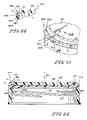
- FIG. 17 is an enlarged sectional view taken along line 17 — 17 of FIG. 15 showing the formation of the monolithic compliant member on the cap to form the inner cap liner and the outer grip ring;
- FIG. 18 is a perspective view of a closure in accordance with another embodiment of the disclosure.
- FIG. 19 is a sectional view taken along line 19 — 19 of FIG. 18 ;
- FIG. 20 is a perspective view of a closure base included in the closure of FIG. 14 before a monolithic compliant member is overmolded onto the cap;
- FIG. 21 is a sectional view taken along line 21 — 21 of FIG. 20 ;
- FIG. 22 is a sectional view (similar to FIG. 19 ) of a closure in accordance with another embodiment of the disclosure.
- FIG. 23 is a partial perspective view of a cap included in the closure of FIG. 22 before a monolithic compliant member is overmolded onto the cap;
- FIG. 24 is a sectional view taken along line 24 — 24 of FIG. 23 .
- a monolithic compliant member 10 is coupled to a cap 12 to provide a liquid container closure 14 as suggested, for example, in FIGS. 1–3 and FIGS. 13–17 .
- Closure 14 mounts on a neck 16 of a container 18 to close an open mouth 20 formed in neck 16 .
- An illustrative compression-molding process for forming monolithic compliant member 10 on cap 12 is shown in FIGS. 9–12
- Monolithic compliant member 10 includes a cap liner 11 , a grip portion 13 illustratively shaped to form a ring, and a series of posts 15 coupled at one end to cap liner 11 and at another end to grip portion 13 as suggested, for example, in FIGS. 2 and 3 .
- Each post 15 is arranged to extend through a companion hole 17 formed in cap 12 to tether cap liner 11 to grip portion 13 to retain monolithic compliant member 10 on cap 12 in a manner shown, for example, in FIG. 3 . It is within the scope of this disclosure to form grip portion 13 in suitable shapes other than a ring.
- Monolithic compliant member 10 is made of a compliant material that yields elastically when a force is applied and thus is deformable to allow cap liner 11 to establish a sealed barrier located, for example, between cap 12 and neck 16 of container 18 upon installation of closure 14 on neck 16 as suggested in FIGS. 1 and 3 .
- Grip portion 13 is made of that same compliant material.
- One characteristic of the compliant material is that it is adapted to move into and through voids formed in cap 12 or associated with molds used to overmold monolithic compliant member 10 onto cap 12 .
- the compliant material used to form grip portion 13 is “softer” than the material used to form cap 12 .
- grip portion 13 provides a high-friction, low-abrasion surface for contact with an end user during contact with closure 14 to open and close container 18 . It is within the scope of this disclosure to use a material having one color to form monolithic compliant member 10 and a material having another color to form cap 12 .
- cap liner 11 includes concentric first and second seal rings 21 , 22 that contact an upwardly facing surface 23 of an annular rim 24 included in neck 16 to establish an “annular seal” therebetween when cap 12 is coupled to neck 16 (as shown in FIGS. 1 , 3 , and 12 ) so that leakage of liquid (not shown) from container 18 through open mouth 20 is blocked.
- Cap liner 11 also includes a mount 26 having a top surface 28 arranged to mate with cap 12 and an opposite bottom surface 30 arranged to support the concentric first and second seal rings 21 , 22 as suggested in FIGS. 4–6 .
- mount 26 is shaped to provide a round disk. It is within the scope of this disclosure to omit seal rings 21 , 22 (and use a portion of mount 26 to effect a seal) or employ one or more seal rings or members in cap liner 11 .
- Mount 26 of cap liner 11 includes a round inner web 32 and an annular outer web 34 surrounding round inner web 32 as suggested in FIGS. 2 and 19 .
- Concentric first and second seal rings 21 , 22 depend from annular outer web 34 as suggested in FIG. 19 .
- Inner web 32 includes an outer peripheral portion terminating at first seal ring 21 to cause first seal ring 21 to surround inner web 32 .
- Inner web 32 includes a central dome 36 formed to include a dome receiver cavity 38 having an opening in top surface 28 .
- Inner web 32 also includes a web membrane 40 arranged to surround central dome 36 and extend radially outwardly from central dome 36 to first seal ring 21 .
- Monolithic compliant member 10 is formed from a compliant material with a preferred Shore A durometer hardness of 58 ⁇ 3, although materials with hardness readings ranging from 24 to 95 are suitable.
- the preferred compliant material is sold as ALPHA SEAL #01-372, available from AlphaGary Corporation of Leominster, Mass.
- suitable materials for use in monolithic compliant member 10 include synthetic or natural rubber, ethylene vinyl alcohol (EVA), linear low-density polyethylene, thermoplastic elastomers, and/or soft polypropylene.
- EVA ethylene vinyl alcohol
- the material may be a laminate of one or more of such compounds or mixtures of one or more of such compounds.
- Cap 12 includes a top wall 62 , a grip support 63 extending around top wall 62 , and an annular skirt 64 depending from grip support 63 to form an interior region 66 of cap 12 as shown, for example, in FIGS. 2 and 10 – 12 .
- Cap 12 also includes, for example, a tamper band 68 coupled to annular skirt 64 by means of frangible bridges 69 or other suitable frangible connectors. It is within the scope of this disclosure to omit tamper band 68 from cap 12 .
- Grip support 63 and top wall 62 cooperate to form a channel 65 receiving grip portion 13 of monolithic compliant member 10 as shown, for example, in FIG. 4 .
- Grip portion 13 is located outside of interior region 66 of cap 12 and arranged to engage an exterior surface of cap 12 as suggested, for example, in FIG. 13 . In the illustrated embodiment, that exterior surface is defined by portions of grip support 63 and top wall 62 .
- grip support 63 and a perimeter edge 61 of top wall 62 cooperate to form an annular channel 65 and grip portion 13 is ring-shaped and located in annular channel 65 . It is within the scope of this disclosure to form grip portion 13 to establish an “endless” grip ring (as illustrated in FIGS. 1 and 2 ) or as one or more segments located on an exterior surface of cap 12 and linked to cap liner 11 .
- annular skirt 64 includes an upper edge 80 .
- Grip support 63 includes an annular lateral wall 81 extending away from perimeter edge 61 of top wall 62 and mating with annular upper edge 80 of annular skirt 64 .
- Annular upper edge 80 and an exterior surface of annular lateral wall 81 cooperate to define a boundary of annular channel 65 formed in cap 12 and engage grip ring 13 located in annular channel 65 as suggested in FIGS. 2 and 3 .
- Annular skirt 64 is arranged as suggested in FIG. 8 to extend in a vertical direction and annular lateral wall 81 is arranged to extend in a horizontal direction to lie in orthogonal relation to annular skirt 64 .
- Annular lateral wall 81 of grip support 63 is formed to include “extrusion” holes 17 as suggested in FIGS. 2 , 4 , 6 , 8 , and 17 . As disclosed herein, plastics material is moved or otherwise extruded through holes 17 during formation of monolithic compliant member 10 on cap 12 to form closure 14 .
- extrusion holes 17 are formed to lie in circumferentially spaced-apart relation to one another in a circular pattern around perimeter edge 61 of top wall 62 . It is within the scope of this disclosure to vary, for example, the size, spacing, and number of these extrusion holes 17 .
- Extrusion holes 17 provide passageways through cap 12 for conducting plastics material between annular channel 65 and interior region 66 during creation of monolithic compliant member 10 on cap 12 .
- extrusion posts 15 extend through extrusion holes 17 to link cap liner 11 to grip portion 13 .
- extrusion posts 15 provides means for tethering grip portion 13 to cap liner 11 to retain monolithic compliant member 10 on cap 12 .
- extrusion posts 15 are arranged to extend vertically to lie in spaced-apart relation to one another.
- annular skirt 64 of cap 12 has a total of four threads 70 with four leads 71 formed in the inner surface 72 of annular skirt 64 .
- the multiple threads and multiple thread leads assist in providing skirt 64 with sufficient flexibility to provide a snap-on/twist-off capability.
- the multiple threads 70 are preferably sized, angled, and pitched so that they can slide over container neck threads 73 in response to downward axial pressure applied during bottling.
- a wide variety of numbers of threads having differing length, height, pitch, and angle of opposite faces may be used in skirt 64 .
- cap 12 is made of high-density polyethylene (HDPE) resin having a density of about 0.95. It is further contemplated that caps 12 may be formed from LDPE, a blend or copolymer of LDPE and HDPE polypropylene (PP), or other lightweight, inexpensive thermoplastic materials suitable for use in compression molding.
- HDPE high-density polyethylene
- frangible bridges 69 include both angled bridges 69 a and vertical bridges 69 b connecting annular skirt 64 to tamper band 68 .
- band 68 included at least eight bridges, including two pairs of angled bridges and two pairs of vertical bridges, although other combinations of bridges may be used.
- the lower edge of annular skirt 64 is defined by a shelf extending axially outwardly so that it has a slightly greater exterior diameter than the remainder of annular skirt 64 .
- a plurality of spaced-apart pads 59 extend down from the lower edge of annular skirt 64 .
- the outer diameter of pads 59 preferably match the outer diameter of the band 68 .
- Pads 59 provide a surface for the upper edge of band 68 to bear against when downward axial pressure is applied to the cap during bottling and when upward axial pressure is applied to the bottom edge of band 68 to assist in ejection of skirt 64 from an injection mold.
- tamper band 68 The exterior and interior diameters of tamper band 68 are slightly larger than those of annular skirt 64 (other than at pads 59 ) to allow band 68 to fit over annular rim 24 on container neck 16 .
- Band 68 has a plurality of ridges 75 formed on its interior surface 76 . Ridges 75 have an angled lower surface 77 and a bridge-severing surface 78 extending transversely from interior surface 50 . Lower surface 77 of ridges 75 are angled to ease passage of skirt 64 and band 68 over rim 24 on neck 16 during the application of downward axial pressure on cap 12 in the course of bottling.
- Bridge-severing surface 78 of ridges 75 are designed to engage rim 24 on neck 16 of container 18 when cap 12 is twisted for removal.
- bridge-severing surface 78 is shown as being disposed on a series of spaced-apart ridges, it is contemplated that a continuous bridge-severing surface could be provided by use of a continuous rim extending transversely from the interior surface of band 68 , rather than spaced-apart ridges.
- a closure 114 includes a cap 112 and a monolithic compliant member 110 formed to include external grip fingers 101 depending from a radially outwardly facing portion 102 of grip portion 13 .
- Cap 112 includes a top wall 62 , an annular skirt 164 , and a tamper band 168 .
- Annular skirt 94 is formed to include upright channels 103 for receiving plastics material to define grip fingers 101 therein.
- Grip fingers 101 are illustratively arranged to lie in circumferentially spaced-apart relation to one another in a frustoconical array as suggested in FIGS. 18 and 19 .
- a closure 214 includes a cap 212 and a monolithic compliant member 210 .
- cap 212 includes a grip support 263 including an annular lateral wall 281 and an annular upright wall 283 .
- Annular lateral wall 281 extends from perimeter edge 61 of top wall 62 .
- Annular upright wall 283 extends from the outer edge of annular lateral wall 281 downwardly to mate with an annular upper edge 280 of annular skirt 264 .
- perimeter edge 61 of top wall 62 , exterior surfaces of annular lateral and upright walls 281 , 283 , and annular upper edge 280 of annular skirt 264 cooperate to define a boundary of annular channel 265 formed in cap 212 and engage grip portion 213 located in annular channel 265 .
- annular upright wall 283 is formed to include extrusion holes 17 .
- Extrusion holes 17 are formed to extend in radially outwardly extending directions from a central vertical axis 201 extending through top wall 62 .
- Each extrusion post 15 extends through one of extrusion holes 17 to tether cap liner 211 to grip portion 213 to retain monolithic compliant member 210 on cap 212 . It is within the scope of this disclosure to form extrusion holes 17 in annular lateral wall 281 .
- a sealing ring 221 is included in cap liner 211 .
- a method of producing a liquid container closure in accordance with the present disclosure comprises the steps for providing a cap 12 having an interior surface defining an interior region 66 , an exterior surface lying outside interior region 66 , and at least one hole or opening 17 extending from the interior surface to the exterior surface and then moving a plastics material through the at least one hole 17 to create a monolithic compliant member 10 having (1) a cap liner 11 located on the interior surface of cap 12 and adapted to mate with a neck 16 of a liquid container 18 received in interior region 66 of cap 12 and (2) a grip portion 13 on the exterior surface of cap 12 .
- a cap liner 11 located on the interior surface of cap 12 and adapted to mate with a neck 16 of a liquid container 18 received in interior region 66 of cap 12 and (2) a grip portion 13 on the exterior surface of cap 12 .
- the moving step includes the steps for applying a plastics material 306 to the interior surface of cap 12 and the compressing plastics material 306 to form cap liner 11 in interior region 66 of cap 12 and to form grip portion 13 on the exterior surface of cap 12 .
- the moving step comprises the steps of placing cap 12 in a mold cavity and injecting a plastics material into a void created in the mold cavity between cap 12 and the companion mold to form monolithic compliant member 10 on cap 12 .
- plastics material used to form monolithic compliant member 10 is heated to a predetermined temperature before it is moved to contact cap 12 .
- FIGS. 9–12 Various illustrative aspects of a compression-molding process for creating a monolithic compliant member on a cap are shown diagrammatically in FIGS. 9–12 .
- a cap e.g., cap 12
- Cap 12 is then transported by conveyor 300 a to a second station 302 so that a plastics material formable (at a later stage) to establish a monolithic compliant member (e.g., member 10 ) can be applied to cap 12 .
- Cap 12 and the plastics material applied thereto are then transported by conveyor 300 b to a third station 303 so that the plastics material applied to cap 12 can be compressed to form, for example, cap liner 11 in the interior region 66 of cap 12 and form grip portion 13 on an exterior surface of cap 12 .
- a liquid container closure 14 comprising a cap 12 , cap liner 11 , and grip portion 13 is now transported by conveyor 300 c to inventory 304 or other satisfactory destination.
- Monolithic compliant member 10 is formed using a compression-molding method which includes extrusion of a plastics material 306 by an extruder 308 (or other suitable dispenser) onto the center of an underside of a cap through a pick-up nozzle provided by extruder 308 as suggested diagrammatically in FIG. 10 .
- a sensor 310 measures the gram weight of the plastics material 306 extruded and provides a signal via controller 312 to cease flow of plastics material 306 from extruder 308 at a predetermined level, typically between 0.440 to 0.460 grams, for a 38 mm opening cap.
- Cap 12 and plastics material 306 cools during transportation via conveyor 300 b to a compression station 303 . Just prior to compression, plastics material 306 has cooled to about 215° C. and is semi-solid.
- a compression punch 314 is then brought down upon the plastics material 306 under high pressure generated by punch mover 316 as suggested diagrammatically in FIGS. 11 and 12 .
- Compression punch 314 has a profile which is machined to be a mirror image of cap liner 11 having one or more sealing surfaces as described herein.
- Plastics material 306 illustratively adheres to cap 12 without use of adhesives or any further addition of heat to cap liner 11 , cap 12 , or grip portion 13 . It is within the scope of this disclosure to adhere cap liner 11 and grip portion 13 to cap 12 so as to cause cap liner 11 and grip portion 13 to hold fast or stick onto cap 12 by or as if by gluing, suction, grasping, or fusing.
- An illustrative apparatus for performing this method of forming a monolithic compliant member is in the KDP50-24 Plastic Liner Molding Machine sold by Oberburg Engineering AG, Ementalstrasse 137, CH-3414, Oberburg, Switzerland. Another illustrative machine would e a Sacmi lining machine PMV238 from Sacmi of Italy.
- Plastics material 306 is applied to the interior surface of cap 12 as suggested in FIG. 11 and then compressed as suggested in FIG. 12 to form cap liner 11 in interior region 66 of cap 12 and form grip portion 36 on the exterior surface of cap 12 .
- the applying step includes the steps of extruding plastics material 306 onto the interior surface of cap 12 , determining the weight of plastics material 306 being extruded onto the interior surface of cap 12 and ceasing the extruding step once the weight of plastics material 306 extruded onto the interior surface reaches a predetermined weight detected during the determining step as suggested in FIGS. 10 and 11 .
- Cap 12 includes a top wall 62 and an annular skirt 64 cooperating with top wall 62 to define interior region 66 and plastics material 306 is applied to a portion of the interior surface located on top wall 62 as suggested in FIG. 11 .
- a molten plastics material is extruded, then cut to form a molten “pellet,” and the pellet is then placed on the cap and arranged to be compressed.
- punch 314 is moved by punch mover 316 into interior region 66 of cap 12 to form cap liner 11 on the interior surface and to move plastics material 306 through an opening 17 formed in cap 12 and plastics material 306 moved through the opening is collected to establish grip portion 13 on the exterior surface of cap 12 .
Abstract
Description
Claims (8)
Priority Applications (2)
| Application Number | Priority Date | Filing Date | Title |
|---|---|---|---|
| US10/669,765 US7007817B2 (en) | 2003-09-24 | 2003-09-24 | Container closure |
| EP04255850A EP1518793A1 (en) | 2003-09-24 | 2004-09-24 | Container closure |
Applications Claiming Priority (1)
| Application Number | Priority Date | Filing Date | Title |
|---|---|---|---|
| US10/669,765 US7007817B2 (en) | 2003-09-24 | 2003-09-24 | Container closure |
Publications (2)
| Publication Number | Publication Date |
|---|---|
| US20050061766A1 US20050061766A1 (en) | 2005-03-24 |
| US7007817B2 true US7007817B2 (en) | 2006-03-07 |
Family
ID=34313751
Family Applications (1)
| Application Number | Title | Priority Date | Filing Date |
|---|---|---|---|
| US10/669,765 Expired - Fee Related US7007817B2 (en) | 2003-09-24 | 2003-09-24 | Container closure |
Country Status (1)
| Country | Link |
|---|---|
| US (1) | US7007817B2 (en) |
Cited By (23)
| Publication number | Priority date | Publication date | Assignee | Title |
|---|---|---|---|---|
| US20040245207A1 (en) * | 1998-10-19 | 2004-12-09 | Playtex Products, Inc. | Container assembly and bottom cap therefor |
| US20070205229A1 (en) * | 2002-07-22 | 2007-09-06 | Schmeisser William C | Multiple Layer Beverage Closure |
| US20070289936A1 (en) * | 2006-06-15 | 2007-12-20 | Owens-Illinois Closure Inc. | Dispensing closure, package and method of manufacture |
| US20080011703A1 (en) * | 2006-04-25 | 2008-01-17 | Schmeisser William C | Overmolded Beverage Closure |
| US20080035674A1 (en) * | 2006-04-25 | 2008-02-14 | Stoneberg Thomas C | Mold-In-Place Two Shot Seal |
| US20080257850A1 (en) * | 2004-11-05 | 2008-10-23 | O'keefe-Broadbent Tara | Container lid with integral gripping surface |
| US20080302753A1 (en) * | 2007-06-08 | 2008-12-11 | Berry Plastics Corporation | Apparatus and method for producing a container closure |
| US20090090721A1 (en) * | 2007-10-09 | 2009-04-09 | Gerard Laurent Buisson | Packaging System With an Overcap |
| US20100308069A1 (en) * | 2007-12-04 | 2010-12-09 | Andrew Peter Sharpe | Cap for a container |
| US8109396B1 (en) | 2006-03-31 | 2012-02-07 | Rexam Healthcare Packaging Inc. | Slide rails and friction surfaces for closure |
| US8167490B2 (en) | 2009-04-22 | 2012-05-01 | Reynolds Consumer Products Inc. | Multilayer stretchy drawstring |
| US8925755B2 (en) | 2010-04-13 | 2015-01-06 | Ipl, Inc. | Tamper evident system and method |
| US20150336716A1 (en) * | 2012-12-31 | 2015-11-26 | Societe Anonyme Des Eaux Minerales D'evian Saeme | Cap for closing a container comprising a neck delimiting an opening and method for manufacturing the same |
| USD760911S1 (en) | 2011-12-15 | 2016-07-05 | Shahid Sheikh | Ice bag cap |
| USD766717S1 (en) | 2011-12-15 | 2016-09-20 | Shahid Sheikh | Ice bag cap |
| US9650179B2 (en) | 2011-12-15 | 2017-05-16 | Proseries Llc | Cap with overmolded gasket anchoring system |
| USD805634S1 (en) * | 2015-08-20 | 2017-12-19 | Emanuele A Mangiafico | Specimen cup and transfer apparatus |
| US20180361003A1 (en) * | 2017-06-15 | 2018-12-20 | 3M Innovative Properties Company | Disinfectant caps |
| US10493447B2 (en) | 2015-08-20 | 2019-12-03 | Allegiance Corporation | Specimen cup and transfer apparatus |
| US11097457B2 (en) * | 2015-02-05 | 2021-08-24 | Obrist Closures Switzerland Gmbh | Method of forming a closure |
| US20230021092A1 (en) * | 2021-07-15 | 2023-01-19 | The Coleman Company, Inc. | Overmolded seal member |
| US11623791B2 (en) * | 2020-12-26 | 2023-04-11 | Zhejiang Haoda Science & Technology Co., Ltd | Container lid and container |
| USD988863S1 (en) | 2020-08-11 | 2023-06-13 | Vanessa Simkins | Silicone bottle lid with straw opening |
Families Citing this family (18)
| Publication number | Priority date | Publication date | Assignee | Title |
|---|---|---|---|---|
| MXPA06014860A (en) * | 2004-06-18 | 2007-03-21 | Silgan Closures Llc | Composite closure with barrier end panel. |
| US20060070996A1 (en) * | 2004-10-06 | 2006-04-06 | Boyle Justin E | Dual material bottle cap |
| US7578404B2 (en) * | 2005-02-04 | 2009-08-25 | Phoenix Closures, Inc. | Tamper evident band closure assembly |
| US8596477B2 (en) * | 2005-12-28 | 2013-12-03 | Silgan White Cap LLC | Retortable package with plastic closure cap |
| US20080072989A1 (en) * | 2006-09-22 | 2008-03-27 | Lepe Jose A | Squeeze resistant flange cover and method of making same |
| JP2008296931A (en) * | 2007-05-30 | 2008-12-11 | Shinko Chemical Co Ltd | Lid body of container |
| FR2921581B1 (en) * | 2007-09-28 | 2009-11-20 | Alcan Packaging Beauty Serv | METHOD AND TOOLS FOR MANUFACTURING A COMPOSITE PIECE, COMPOSITE CAP OBTAINED BY SUCH A METHOD OR TO SUCH TOOLS |
| EP2058379A1 (en) | 2007-11-09 | 2009-05-13 | ACTEGA DS GmbH | Method for manufacturing a closure |
| US20090166240A1 (en) * | 2007-12-26 | 2009-07-02 | Scarola Leonard S | Container with grippable body and lid |
| US20090200324A1 (en) * | 2008-02-07 | 2009-08-13 | Extron International Limited | Foodware Set That Includes A Multifunction Cover-Base Assembly |
| DE102008036096B4 (en) * | 2008-08-04 | 2016-05-19 | Mn-Beteiligungs-Gmbh | Filtration system with fluid couplings |
| ITVE20080076A1 (en) * | 2008-10-14 | 2010-04-15 | Biosigma Srl | SCREW CAP FOR TUBES, PARTICULARLY FOR CRYOGENIC USE.- |
| US20100308003A1 (en) * | 2009-06-04 | 2010-12-09 | Adiri, Inc. | Modular and Natural Infant Feeding Container |
| RU2011143963A (en) * | 2011-11-01 | 2013-05-10 | Дмитрий Владимирович Вихорев | METHOD FOR INCREASING CLUTCH ON PET COVERS |
| WO2015195516A1 (en) * | 2014-06-19 | 2015-12-23 | Sheikh Shahid | Cap with overmolded gasket anchoring system |
| SE542073C2 (en) * | 2015-11-10 | 2020-02-18 | Trelleborg Sealing Solutions Kalmar Ab | Sealing cap and method for manufacturing a sealing cap |
| US10961024B2 (en) | 2018-04-09 | 2021-03-30 | Berry Global, Inc. | Closure |
| EP3647221A1 (en) * | 2018-10-29 | 2020-05-06 | Tetra Laval Holdings & Finance S.A. | Cap angular orientation |
Citations (30)
| Publication number | Priority date | Publication date | Assignee | Title |
|---|---|---|---|---|
| US2074830A (en) * | 1934-11-27 | 1937-03-23 | Colt S Mfg Co | Container closure |
| US2394135A (en) * | 1942-12-24 | 1946-02-05 | Max E Baar | Container closure |
| US2752059A (en) | 1950-11-08 | 1956-06-26 | Continental Can Co | Closure with sealing pad having concentric ribs |
| US2768762A (en) | 1952-10-01 | 1956-10-30 | William Herter | Sealing members or elements |
| US3095991A (en) | 1961-11-17 | 1963-07-02 | Paniagua Juan Garcia | Combination bottle cap seal and opener |
| US3195754A (en) | 1963-03-18 | 1965-07-20 | Continental Can Co | Aluminum containing seal liners for beer containers and like substances |
| US3628704A (en) | 1969-12-10 | 1971-12-21 | Diamond Int Corp | Container with venting gasket |
| US4379512A (en) | 1979-11-24 | 1983-04-12 | Toyo Seikan Kaisha, Ltd. | Closure having an improved liner |
| US4429802A (en) | 1982-05-28 | 1984-02-07 | Anchor Hocking Corporation | Linerless closure cap |
| US4440820A (en) * | 1980-12-24 | 1984-04-03 | Fujitsu Limited | Plastic molding |
| US4444329A (en) * | 1982-09-29 | 1984-04-24 | Vollers Gary L | Container cap and seal formation of indicia |
| US4488676A (en) | 1983-07-19 | 1984-12-18 | Tri-Plas Inc. | Container lid |
| US4625875A (en) | 1985-02-04 | 1986-12-02 | Carr Joseph J | Tamper-evident closure |
| US4658976A (en) | 1983-04-15 | 1987-04-21 | Aluminum Company Of America | Lined plastic closure |
| FR2593148A1 (en) | 1986-01-22 | 1987-07-24 | Retief Charles | CLOSURE FOR CONTAINERS, AND METHOD FOR MANUFACTURING SUCH CLOSURE. |
| US4741447A (en) | 1987-04-27 | 1988-05-03 | American National Can Company | Linerless cap closure |
| US4744481A (en) | 1987-04-06 | 1988-05-17 | Poly-Seal Corporation | Closure for containers |
| US4878589A (en) | 1987-04-27 | 1989-11-07 | American National Can Company | Linerless cap closure |
| US5042680A (en) | 1990-08-03 | 1991-08-27 | Tri-Plas, Inc. | Reclosable container assembly |
| US5213224A (en) | 1990-08-09 | 1993-05-25 | Portola Packaging, Inc. | Snap-on, screw-off cap and container neck |
| US5439124A (en) | 1991-09-17 | 1995-08-08 | Tetra Laval Holdings & Finance S.A. | Closure unit on flowable product container |
| US5553727A (en) | 1995-04-27 | 1996-09-10 | Consumer Cap Corporation | Tamper-evident cap and neck finish |
| US5762218A (en) | 1994-10-06 | 1998-06-09 | Franz Rossberg | Plastic closure retained by snapping over bottle neck bead |
| FR2759351A1 (en) | 1997-02-11 | 1998-08-14 | Axia Cap | Container dispenser cap for liquid or paste product |
| US5868273A (en) * | 1996-10-11 | 1999-02-09 | Dart Industries Inc. | Canister with pressure resistant sealing lid |
| US5979690A (en) | 1997-11-19 | 1999-11-09 | Berry Plastic Corporation | Reclosable rectangular container assembly with tamper indicator |
| US6142325A (en) * | 1998-10-19 | 2000-11-07 | Playtex Products, Inc. | Container assembly and bottom cap therefor |
| EP1065149A2 (en) | 1999-07-01 | 2001-01-03 | Dragon Plastics Limited | Moulded closure and method of manufacture |
| US20020113032A1 (en) | 2001-02-22 | 2002-08-22 | Blomdahl Cori M. | Non-dispensing closure |
| US20020162818A1 (en) * | 2001-05-04 | 2002-11-07 | Williams Charles L. | Beverage container closure |
Family Cites Families (1)
| Publication number | Priority date | Publication date | Assignee | Title |
|---|---|---|---|---|
| SE423659B (en) * | 1980-09-26 | 1982-05-17 | Ericsson Telefon Ab L M | COUPLING |
-
2003
- 2003-09-24 US US10/669,765 patent/US7007817B2/en not_active Expired - Fee Related
Patent Citations (33)
| Publication number | Priority date | Publication date | Assignee | Title |
|---|---|---|---|---|
| US2074830A (en) * | 1934-11-27 | 1937-03-23 | Colt S Mfg Co | Container closure |
| US2394135A (en) * | 1942-12-24 | 1946-02-05 | Max E Baar | Container closure |
| US2752059A (en) | 1950-11-08 | 1956-06-26 | Continental Can Co | Closure with sealing pad having concentric ribs |
| US2768762A (en) | 1952-10-01 | 1956-10-30 | William Herter | Sealing members or elements |
| US3095991A (en) | 1961-11-17 | 1963-07-02 | Paniagua Juan Garcia | Combination bottle cap seal and opener |
| US3195754A (en) | 1963-03-18 | 1965-07-20 | Continental Can Co | Aluminum containing seal liners for beer containers and like substances |
| US3628704A (en) | 1969-12-10 | 1971-12-21 | Diamond Int Corp | Container with venting gasket |
| US4379512A (en) | 1979-11-24 | 1983-04-12 | Toyo Seikan Kaisha, Ltd. | Closure having an improved liner |
| US4440820A (en) * | 1980-12-24 | 1984-04-03 | Fujitsu Limited | Plastic molding |
| US4429802A (en) | 1982-05-28 | 1984-02-07 | Anchor Hocking Corporation | Linerless closure cap |
| US4444329A (en) * | 1982-09-29 | 1984-04-24 | Vollers Gary L | Container cap and seal formation of indicia |
| US4658976A (en) | 1983-04-15 | 1987-04-21 | Aluminum Company Of America | Lined plastic closure |
| US4488676A (en) | 1983-07-19 | 1984-12-18 | Tri-Plas Inc. | Container lid |
| US4625875A (en) | 1985-02-04 | 1986-12-02 | Carr Joseph J | Tamper-evident closure |
| FR2593148A1 (en) | 1986-01-22 | 1987-07-24 | Retief Charles | CLOSURE FOR CONTAINERS, AND METHOD FOR MANUFACTURING SUCH CLOSURE. |
| US4754892A (en) * | 1986-01-22 | 1988-07-05 | Retief Charles T | Closure for a container |
| US4744481A (en) | 1987-04-06 | 1988-05-17 | Poly-Seal Corporation | Closure for containers |
| US4878589A (en) | 1987-04-27 | 1989-11-07 | American National Can Company | Linerless cap closure |
| US4741447A (en) | 1987-04-27 | 1988-05-03 | American National Can Company | Linerless cap closure |
| US5042680A (en) | 1990-08-03 | 1991-08-27 | Tri-Plas, Inc. | Reclosable container assembly |
| US5213224A (en) | 1990-08-09 | 1993-05-25 | Portola Packaging, Inc. | Snap-on, screw-off cap and container neck |
| US5439124A (en) | 1991-09-17 | 1995-08-08 | Tetra Laval Holdings & Finance S.A. | Closure unit on flowable product container |
| US5762218A (en) | 1994-10-06 | 1998-06-09 | Franz Rossberg | Plastic closure retained by snapping over bottle neck bead |
| US5553727C1 (en) | 1995-04-27 | 2001-09-04 | Rical Sa | Tamper-evident cap and neck finish |
| US5553727A (en) | 1995-04-27 | 1996-09-10 | Consumer Cap Corporation | Tamper-evident cap and neck finish |
| US5868273A (en) * | 1996-10-11 | 1999-02-09 | Dart Industries Inc. | Canister with pressure resistant sealing lid |
| FR2759351A1 (en) | 1997-02-11 | 1998-08-14 | Axia Cap | Container dispenser cap for liquid or paste product |
| US5979690A (en) | 1997-11-19 | 1999-11-09 | Berry Plastic Corporation | Reclosable rectangular container assembly with tamper indicator |
| US6142325A (en) * | 1998-10-19 | 2000-11-07 | Playtex Products, Inc. | Container assembly and bottom cap therefor |
| EP1065149A2 (en) | 1999-07-01 | 2001-01-03 | Dragon Plastics Limited | Moulded closure and method of manufacture |
| US20020113032A1 (en) | 2001-02-22 | 2002-08-22 | Blomdahl Cori M. | Non-dispensing closure |
| US6481589B2 (en) * | 2001-02-22 | 2002-11-19 | Seaquist Closures Foreign, Inc. | Non-dispensing closure |
| US20020162818A1 (en) * | 2001-05-04 | 2002-11-07 | Williams Charles L. | Beverage container closure |
Cited By (31)
| Publication number | Priority date | Publication date | Assignee | Title |
|---|---|---|---|---|
| US7370770B2 (en) * | 1998-10-19 | 2008-05-13 | Playtex Products, Inc. | Container assembly and bottom cap therefor |
| US20040245207A1 (en) * | 1998-10-19 | 2004-12-09 | Playtex Products, Inc. | Container assembly and bottom cap therefor |
| US20070205229A1 (en) * | 2002-07-22 | 2007-09-06 | Schmeisser William C | Multiple Layer Beverage Closure |
| US20080257850A1 (en) * | 2004-11-05 | 2008-10-23 | O'keefe-Broadbent Tara | Container lid with integral gripping surface |
| US8109396B1 (en) | 2006-03-31 | 2012-02-07 | Rexam Healthcare Packaging Inc. | Slide rails and friction surfaces for closure |
| US7887731B2 (en) | 2006-04-25 | 2011-02-15 | Rexam Closures And Containers Inc. | Method of molding an overmolded beverage closure |
| US20080011703A1 (en) * | 2006-04-25 | 2008-01-17 | Schmeisser William C | Overmolded Beverage Closure |
| US20080035674A1 (en) * | 2006-04-25 | 2008-02-14 | Stoneberg Thomas C | Mold-In-Place Two Shot Seal |
| US8608001B2 (en) | 2006-04-25 | 2013-12-17 | Berry Plastics Corporation | Mold-in-place two shot seal |
| US20070289936A1 (en) * | 2006-06-15 | 2007-12-20 | Owens-Illinois Closure Inc. | Dispensing closure, package and method of manufacture |
| US20080302753A1 (en) * | 2007-06-08 | 2008-12-11 | Berry Plastics Corporation | Apparatus and method for producing a container closure |
| US9242782B2 (en) | 2007-10-09 | 2016-01-26 | The Folger Coffee Company | Visual vacuum indicator |
| US20090110777A1 (en) * | 2007-10-09 | 2009-04-30 | Gerard Laurent Buisson | Visual Vacuum Indicator |
| US20090090721A1 (en) * | 2007-10-09 | 2009-04-09 | Gerard Laurent Buisson | Packaging System With an Overcap |
| US10081475B2 (en) * | 2007-10-09 | 2018-09-25 | The Folger Coffee Company | Packaging system with an overcap |
| US20100308069A1 (en) * | 2007-12-04 | 2010-12-09 | Andrew Peter Sharpe | Cap for a container |
| US8167490B2 (en) | 2009-04-22 | 2012-05-01 | Reynolds Consumer Products Inc. | Multilayer stretchy drawstring |
| US8925755B2 (en) | 2010-04-13 | 2015-01-06 | Ipl, Inc. | Tamper evident system and method |
| USD760911S1 (en) | 2011-12-15 | 2016-07-05 | Shahid Sheikh | Ice bag cap |
| USD766717S1 (en) | 2011-12-15 | 2016-09-20 | Shahid Sheikh | Ice bag cap |
| US9650179B2 (en) | 2011-12-15 | 2017-05-16 | Proseries Llc | Cap with overmolded gasket anchoring system |
| US20150336716A1 (en) * | 2012-12-31 | 2015-11-26 | Societe Anonyme Des Eaux Minerales D'evian Saeme | Cap for closing a container comprising a neck delimiting an opening and method for manufacturing the same |
| US10265897B2 (en) * | 2012-12-31 | 2019-04-23 | SOCIETE ANONYME DES EAUX MINERALES D'EVIAN et en abrégé “S.A.M.E” | Cap for closing a container comprising a neck delimiting an opening and method for manufacturing the same |
| US11097457B2 (en) * | 2015-02-05 | 2021-08-24 | Obrist Closures Switzerland Gmbh | Method of forming a closure |
| USD805634S1 (en) * | 2015-08-20 | 2017-12-19 | Emanuele A Mangiafico | Specimen cup and transfer apparatus |
| US10493447B2 (en) | 2015-08-20 | 2019-12-03 | Allegiance Corporation | Specimen cup and transfer apparatus |
| US10617780B2 (en) * | 2017-06-15 | 2020-04-14 | 3M Innovative Properties Company | Disinfectant caps |
| US20180361003A1 (en) * | 2017-06-15 | 2018-12-20 | 3M Innovative Properties Company | Disinfectant caps |
| USD988863S1 (en) | 2020-08-11 | 2023-06-13 | Vanessa Simkins | Silicone bottle lid with straw opening |
| US11623791B2 (en) * | 2020-12-26 | 2023-04-11 | Zhejiang Haoda Science & Technology Co., Ltd | Container lid and container |
| US20230021092A1 (en) * | 2021-07-15 | 2023-01-19 | The Coleman Company, Inc. | Overmolded seal member |
Also Published As
| Publication number | Publication date |
|---|---|
| US20050061766A1 (en) | 2005-03-24 |
Similar Documents
| Publication | Publication Date | Title |
|---|---|---|
| US7007817B2 (en) | Container closure | |
| US7097790B2 (en) | Method of producing a container closure | |
| US7588155B2 (en) | Beverage container closure | |
| US8071004B2 (en) | Closure having band with internal thread formed by impression | |
| US4573597A (en) | Containers | |
| US20190062007A1 (en) | Closure With Angled Plug Seal | |
| US4476987A (en) | Bottle caps | |
| US6871764B2 (en) | Beverage closure with open/close spout and protected seal surfaces | |
| CN101605699B (en) | Lightweight container | |
| US20080067142A1 (en) | Sealing Means for a Closure, Closure and Process | |
| US6102227A (en) | Snap-on cap with twist on/off reclosure lid | |
| US20080111276A1 (en) | Grip cap | |
| US20080302753A1 (en) | Apparatus and method for producing a container closure | |
| AU2005331483B2 (en) | Sealing means for a closure, closure and process | |
| AU2006290773A1 (en) | Closure with barrier liner | |
| EP1457423B1 (en) | Container main body made of synthetic resin and preforming mold device | |
| US20240101315A1 (en) | Single anchor closure | |
| US20070205229A1 (en) | Multiple Layer Beverage Closure | |
| EP0311693A1 (en) | Plastic cap | |
| EP1518793A1 (en) | Container closure | |
| US4951830A (en) | Snap-on closure with corking skirt | |
| US20210179324A1 (en) | Tethered container closure | |
| EP2033906B1 (en) | Anti-choking safety cap assembly for a container, containers therewith and method for production of a filled container with an anti-choking cap assembly | |
| US20040188375A1 (en) | Linerless plastic closure with a sealing lip | |
| AU725401B2 (en) | Hermetically sealed container with closure insert |
Legal Events
| Date | Code | Title | Description |
|---|---|---|---|
| AS | Assignment |
Owner name: BERRY PLASTICS CORPORATION, INDIANA Free format text: ASSIGNMENT OF ASSIGNORS INTEREST;ASSIGNOR:JOCHEM, DAVID J.;REEL/FRAME:014542/0324 Effective date: 20030917 |
|
| AS | Assignment |
Owner name: FLEET NATIONAL BANK, AS COLLATERAL AGENT, MASSACHU Free format text: SECURITY AGREEMENT;ASSIGNOR:BERRY PLASTICS CORPORATION;REEL/FRAME:016164/0241 Effective date: 20050603 |
|
| AS | Assignment |
Owner name: CREDIT SUISSE, AS ADMINISTRATIVE AGENT,NEW YORK Free format text: SECURITY AGREEMENT;ASSIGNOR:BERRY PLASTICS CORPORATION;REEL/FRAME:018291/0155 Effective date: 20060920 Owner name: CREDIT SUISSE, AS ADMINISTRATIVE AGENT, NEW YORK Free format text: SECURITY AGREEMENT;ASSIGNOR:BERRY PLASTICS CORPORATION;REEL/FRAME:018291/0155 Effective date: 20060920 |
|
| AS | Assignment |
Owner name: WELLS FARGO BANK, N.A., AS COLLATERAL AGENT,CONNEC Free format text: SECOND LIEN PATENT SECURITY AGREEMENT;ASSIGNORS:BERRY PLASTICS CORPORATION;BERRY STERLING CORPORATION;KERR GROUP, INC.;AND OTHERS;REEL/FRAME:018407/0074 Effective date: 20060920 Owner name: WELLS FARGO BANK, N.A., AS COLLATERAL AGENT, CONNE Free format text: SECOND LIEN PATENT SECURITY AGREEMENT;ASSIGNORS:BERRY PLASTICS CORPORATION;BERRY STERLING CORPORATION;KERR GROUP, INC.;AND OTHERS;REEL/FRAME:018407/0074 Effective date: 20060920 |
|
| AS | Assignment |
Owner name: BERRY PLASTICS CORPORATION,INDIANA Free format text: RELEASE OF SECURITY INTEREST IN PATENT COLLATERAL (REEL/FRAME NO. 018291/0155);ASSIGNOR:CREDIT SUISSE, CAYMAN ISLANDS BRANCH;REEL/FRAME:019111/0266 Effective date: 20070403 Owner name: BERRY PLASTICS CORPORATION, INDIANA Free format text: RELEASE OF SECURITY INTEREST IN PATENT COLLATERAL (REEL/FRAME NO. 018291/0155);ASSIGNOR:CREDIT SUISSE, CAYMAN ISLANDS BRANCH;REEL/FRAME:019111/0266 Effective date: 20070403 |
|
| AS | Assignment |
Owner name: BANK OF AMERICA, N.A., AS ABL COLLATERAL AGENT,NOR Free format text: SECOND AMENDED AND RESTATED FIRST LIEN INTELLECTUAL PROPERTY SECURITY AGREEMENT;ASSIGNOR:BERRY PLASTICS HOLDING CORPORATION;REEL/FRAME:019147/0479 Effective date: 20070403 Owner name: CREDIT SUISSE, CAYMAN ISLANDS BRANCH, AS TERM COLL Free format text: SECOND AMENDED AND RESTATED FIRST LIEN INTELLECTUAL PROPERTY SECURITY AGREEMENT;ASSIGNOR:BERRY PLASTICS HOLDING CORPORATION;REEL/FRAME:019147/0479 Effective date: 20070403 Owner name: BANK OF AMERICA, N.A., AS ABL COLLATERAL AGENT, NO Free format text: SECOND AMENDED AND RESTATED FIRST LIEN INTELLECTUAL PROPERTY SECURITY AGREEMENT;ASSIGNOR:BERRY PLASTICS HOLDING CORPORATION;REEL/FRAME:019147/0479 Effective date: 20070403 |
|
| AS | Assignment |
Owner name: BANK OF AMERICA, N.A., AS COLLATERAL AGENT, CALIFO Free format text: BRIDGE LOAN FIRST LIEN INTELLECTUAL PROPERTY SECURITY AGREEMENT;ASSIGNORS:BERRY PLASTICS CORPORATION;BERRY STERLING CORPORATION;CAPTIVE PLASTICS, INC.;AND OTHERS;REEL/FRAME:020638/0249 Effective date: 20080205 Owner name: BANK OF AMERICA, N.A., AS COLLATERAL AGENT,CALIFOR Free format text: BRIDGE LOAN FIRST LIEN INTELLECTUAL PROPERTY SECURITY AGREEMENT;ASSIGNORS:BERRY PLASTICS CORPORATION;BERRY STERLING CORPORATION;CAPTIVE PLASTICS, INC.;AND OTHERS;REEL/FRAME:020638/0249 Effective date: 20080205 |
|
| AS | Assignment |
Owner name: BERRY PLASTICS CORPORATION, INDIANA Free format text: RELEASE OF BRIDGE 1ST LIEN SECURITY AGREEMENT;ASSIGNOR:BANK OF AMERICA, N.A.;REEL/FRAME:020845/0198 Effective date: 20080421 Owner name: BERRY STERLING CORPORATION, INDIANA Free format text: RELEASE OF BRIDGE 1ST LIEN SECURITY AGREEMENT;ASSIGNOR:BANK OF AMERICA, N.A.;REEL/FRAME:020845/0198 Effective date: 20080421 Owner name: CAPTIVE PLASTICS, INC., NEW JERSEY Free format text: RELEASE OF BRIDGE 1ST LIEN SECURITY AGREEMENT;ASSIGNOR:BANK OF AMERICA, N.A.;REEL/FRAME:020845/0198 Effective date: 20080421 Owner name: GRAFCO INDUSTRIES LIMITED PARTNERSHIP, NEW JERSEY Free format text: RELEASE OF BRIDGE 1ST LIEN SECURITY AGREEMENT;ASSIGNOR:BANK OF AMERICA, N.A.;REEL/FRAME:020845/0198 Effective date: 20080421 Owner name: LANDIS PLASTICS, LLC, ILLINOIS Free format text: RELEASE OF BRIDGE 1ST LIEN SECURITY AGREEMENT;ASSIGNOR:BANK OF AMERICA, N.A.;REEL/FRAME:020845/0198 Effective date: 20080421 Owner name: SETCO, LLC, CALIFORNIA Free format text: RELEASE OF BRIDGE 1ST LIEN SECURITY AGREEMENT;ASSIGNOR:BANK OF AMERICA, N.A.;REEL/FRAME:020845/0198 Effective date: 20080421 Owner name: TUBED PRODUCTS, LLC, MASSACHUSETTS Free format text: RELEASE OF BRIDGE 1ST LIEN SECURITY AGREEMENT;ASSIGNOR:BANK OF AMERICA, N.A.;REEL/FRAME:020845/0198 Effective date: 20080421 Owner name: WELLS FARGO BANK, N.A., CONNECTICUT Free format text: SECURITY AGREEMENT;ASSIGNORS:BERRY PLASTICS CORPORATION;BERRY STERLING CORPORATION;CAPTIVE PLASTICS, INC.;AND OTHERS;REEL/FRAME:020845/0301 Effective date: 20080421 Owner name: BERRY PLASTICS CORPORATION,INDIANA Free format text: RELEASE OF BRIDGE 1ST LIEN SECURITY AGREEMENT;ASSIGNOR:BANK OF AMERICA, N.A.;REEL/FRAME:020845/0198 Effective date: 20080421 Owner name: BERRY STERLING CORPORATION,INDIANA Free format text: RELEASE OF BRIDGE 1ST LIEN SECURITY AGREEMENT;ASSIGNOR:BANK OF AMERICA, N.A.;REEL/FRAME:020845/0198 Effective date: 20080421 Owner name: CAPTIVE PLASTICS, INC.,NEW JERSEY Free format text: RELEASE OF BRIDGE 1ST LIEN SECURITY AGREEMENT;ASSIGNOR:BANK OF AMERICA, N.A.;REEL/FRAME:020845/0198 Effective date: 20080421 Owner name: GRAFCO INDUSTRIES LIMITED PARTNERSHIP,NEW JERSEY Free format text: RELEASE OF BRIDGE 1ST LIEN SECURITY AGREEMENT;ASSIGNOR:BANK OF AMERICA, N.A.;REEL/FRAME:020845/0198 Effective date: 20080421 Owner name: LANDIS PLASTICS, LLC,ILLINOIS Free format text: RELEASE OF BRIDGE 1ST LIEN SECURITY AGREEMENT;ASSIGNOR:BANK OF AMERICA, N.A.;REEL/FRAME:020845/0198 Effective date: 20080421 Owner name: SETCO, LLC,CALIFORNIA Free format text: RELEASE OF BRIDGE 1ST LIEN SECURITY AGREEMENT;ASSIGNOR:BANK OF AMERICA, N.A.;REEL/FRAME:020845/0198 Effective date: 20080421 Owner name: TUBED PRODUCTS, LLC,MASSACHUSETTS Free format text: RELEASE OF BRIDGE 1ST LIEN SECURITY AGREEMENT;ASSIGNOR:BANK OF AMERICA, N.A.;REEL/FRAME:020845/0198 Effective date: 20080421 Owner name: WELLS FARGO BANK, N.A.,CONNECTICUT Free format text: SECURITY AGREEMENT;ASSIGNORS:BERRY PLASTICS CORPORATION;BERRY STERLING CORPORATION;CAPTIVE PLASTICS, INC.;AND OTHERS;REEL/FRAME:020845/0301 Effective date: 20080421 |
|
| AS | Assignment |
Owner name: BERRY PLASTICS CORPORATION, INDIANA Free format text: RELEASE OF SECURITY INTEREST AT REEL 016164 FRAME 0241;ASSIGNOR:DEUTSCHE BANK TRUST COMPANY AMERICAS;REEL/FRAME:020866/0565 Effective date: 20060920 |
|
| FPAY | Fee payment |
Year of fee payment: 4 |
|
| REMI | Maintenance fee reminder mailed | ||
| LAPS | Lapse for failure to pay maintenance fees | ||
| STCH | Information on status: patent discontinuation |
Free format text: PATENT EXPIRED DUE TO NONPAYMENT OF MAINTENANCE FEES UNDER 37 CFR 1.362 |
|
| FP | Lapsed due to failure to pay maintenance fee |
Effective date: 20140307 |
|
| AS | Assignment |
Owner name: LANDIS PLASTICS, LLC, DELAWARE Free format text: RELEASE BY SECURED PARTY;ASSIGNOR:WELLS FARGO BANK, N.A., AS COLLATERAL AGENT;REEL/FRAME:049598/0731 Effective date: 20190625 Owner name: SETCO, LLC, CALIFORNIA Free format text: RELEASE BY SECURED PARTY;ASSIGNOR:WELLS FARGO BANK, N.A., AS COLLATERAL AGENT;REEL/FRAME:049598/0731 Effective date: 20190625 Owner name: BERRY GLOBAL, INC., INDIANA Free format text: RELEASE BY SECURED PARTY;ASSIGNOR:WELLS FARGO BANK, N.A., AS COLLATERAL AGENT;REEL/FRAME:049598/0731 Effective date: 20190625 Owner name: KERR GROUP, LLC, CALIFORNIA Free format text: RELEASE BY SECURED PARTY;ASSIGNOR:WELLS FARGO BANK, N.A., AS COLLATERAL AGENT;REEL/FRAME:049598/0731 Effective date: 20190625 Owner name: CAPTIVE PLASTICS, INC., NEW JERSEY Free format text: RELEASE BY SECURED PARTY;ASSIGNOR:WELLS FARGO BANK, N.A., AS COLLATERAL AGENT;REEL/FRAME:049598/0731 Effective date: 20190625 Owner name: GRAFCO INDUSTRIES LIMITED PARTNERSHIP, NEW JERSEY Free format text: RELEASE BY SECURED PARTY;ASSIGNOR:WELLS FARGO BANK, N.A., AS COLLATERAL AGENT;REEL/FRAME:049598/0731 Effective date: 20190625 Owner name: PESCOR, INC., TEXAS Free format text: RELEASE BY SECURED PARTY;ASSIGNOR:WELLS FARGO BANK, N.A., AS COLLATERAL AGENT;REEL/FRAME:049598/0731 Effective date: 20190625 Owner name: TUBED PRODUCTS LLC, MASSACHUSETTS Free format text: RELEASE BY SECURED PARTY;ASSIGNOR:WELLS FARGO BANK, N.A., AS COLLATERAL AGENT;REEL/FRAME:049598/0731 Effective date: 20190625 Owner name: BERRY STERLING CORPORATION, INDIANA Free format text: RELEASE BY SECURED PARTY;ASSIGNOR:WELLS FARGO BANK, N.A., AS COLLATERAL AGENT;REEL/FRAME:049598/0731 Effective date: 20190625 |