US7011170B2 - Increased projection for compacts of a rolling cone drill bit - Google Patents
Increased projection for compacts of a rolling cone drill bit Download PDFInfo
- Publication number
- US7011170B2 US7011170B2 US10/690,943 US69094303A US7011170B2 US 7011170 B2 US7011170 B2 US 7011170B2 US 69094303 A US69094303 A US 69094303A US 7011170 B2 US7011170 B2 US 7011170B2
- Authority
- US
- United States
- Prior art keywords
- bit
- holes
- cone
- depressions
- compacts
- Prior art date
- Legal status (The legal status is an assumption and is not a legal conclusion. Google has not performed a legal analysis and makes no representation as to the accuracy of the status listed.)
- Expired - Lifetime, expires
Links
- 238000005096 rolling process Methods 0.000 title abstract description 3
- 241000237942 Conidae Species 0.000 claims description 30
- 230000015572 biosynthetic process Effects 0.000 description 12
- 238000005755 formation reaction Methods 0.000 description 12
- 239000000463 material Substances 0.000 description 4
- 230000035515 penetration Effects 0.000 description 4
- 239000004927 clay Substances 0.000 description 3
- 239000000314 lubricant Substances 0.000 description 3
- 229910052751 metal Inorganic materials 0.000 description 3
- 239000002184 metal Substances 0.000 description 3
- 238000005553 drilling Methods 0.000 description 2
- 229910000831 Steel Inorganic materials 0.000 description 1
- 230000002706 hydrostatic effect Effects 0.000 description 1
- 238000003780 insertion Methods 0.000 description 1
- 230000037431 insertion Effects 0.000 description 1
- 238000003801 milling Methods 0.000 description 1
- 230000000149 penetrating effect Effects 0.000 description 1
- 239000011435 rock Substances 0.000 description 1
- 239000010959 steel Substances 0.000 description 1
- UONOETXJSWQNOL-UHFFFAOYSA-N tungsten carbide Chemical compound [W+]#[C-] UONOETXJSWQNOL-UHFFFAOYSA-N 0.000 description 1
Images


Classifications
-
- E—FIXED CONSTRUCTIONS
- E21—EARTH DRILLING; MINING
- E21B—EARTH DRILLING, e.g. DEEP DRILLING; OBTAINING OIL, GAS, WATER, SOLUBLE OR MELTABLE MATERIALS OR A SLURRY OF MINERALS FROM WELLS
- E21B10/00—Drill bits
- E21B10/08—Roller bits
-
- E—FIXED CONSTRUCTIONS
- E21—EARTH DRILLING; MINING
- E21B—EARTH DRILLING, e.g. DEEP DRILLING; OBTAINING OIL, GAS, WATER, SOLUBLE OR MELTABLE MATERIALS OR A SLURRY OF MINERALS FROM WELLS
- E21B10/00—Drill bits
- E21B10/08—Roller bits
- E21B10/16—Roller bits characterised by tooth form or arrangement
Definitions
- This invention relates in general to earth-boring rolling cone drill bits, and in particular to depressions milled on the surface of the cone shell between compacts to increase effective compact projection.
- One type of earth-boring drill bit particularly for oil and gas wells, has three rotating cones.
- the cones are mounted on bit legs that extend downward from a bit body. As the bit body rotates, each of the cones rotates about its own axis. Drilling mud pumped down the drill string flows out nozzles on the bit body.
- a plurality of teeth are formed on the cones.
- the teeth are hard metal compacts press-fitted into holes drilled in the cone shell.
- the compacts are arranged in circumferentially extending rows.
- Each compact has a cylindrical base and integral cutting tip, the cutting tip protruding from the cone shell.
- the lengths of the cutting tips and the density of the compacts within each row vary depending upon the type of formation being drilled. In medium and soft formations, typically the spacing between compacts and the projection of the cutting tips are greater than in hard formation bits. If the projection is too long, then the compacts tend to fracture.
- the clay can pack between the teeth, resulting in bit balling. Designing the nozzles of the bit properly reduces the tendency to bit ball. However, in some rock formations, the clay material sticks to the bottom of the borehole instead of sticking to the bit. This bottom balling is a result of the shale in the formation and reduces the rate of penetration.
- the bit of this invention has compacts with a slightly increased effective projection. Slightly increasing the effective projection of the compacts significantly increases the rate of penetration in formations that tend to cause bottom balling.
- the effective projection of the compacts is preferably increased by forming depressions on the cone shell between the holes within a row of compacts. These depressions are preferably milled in the cone shell. Each depression is preferably a flat surface that is located in a plane perpendicular to a radial line from the axis of rotation of the cone.
- the flats are located only on the leading and trailing sides on the holes in the preferred embodiment.
- the inward and outward sides, relative to the axis of the cone, preferably remain conical. Because of the flats, the compacts penetrate slightly deeper before the cone steel comes into contact with the formation or bottom balling material.
- FIG. 1 is a side view of an earth-boring bit constructed in accordance with this invention.
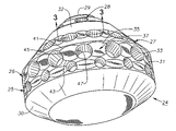
- FIG. 2 is an enlarged perspective view of one of the cone shells suitable for the bit of FIG. 1 , with the compacts and the trimmer inserts removed.
- FIG. 3 is a sectional view of a portion of the cone shell of FIG. 2 taken along the line 3 — 3 , but showing two of the compacts installed.
- bit 11 has a bit body 13 with a threaded section 14 on its upper end for attachment to a drill string.
- Bit body 13 has at least one bit leg 15 , and in this embodiment, three bit legs 15 (only two shown). Bit legs 15 are spaced 120° apart from each about the axis of rotation of bit body 13 .
- a cone 17 is rotatably mounted to a depending bearing pin (not shown) extending inward from each of the bit legs 15 .
- Cones 17 are generally conical and rotate on lubricated bearings.
- a lubricant compensator 19 for each bit leg 15 supplies lubricant to the bearings and reduces pressure differential between the lubricant and the hydrostatic pressure on the exterior.
- a plurality of compacts 21 are mounted to each cone 17 for disintegrating the earth formation.
- Compacts 21 are located in circumferential rows that extend around the axis of each cone 17 .
- Bit legs 15 are positioned so that compacts 21 on one cone 17 will intermesh with compacts 21 on adjacent cones 17 .
- the embodiment of FIG. 1 also shows a row 23 of trimmer inserts. Trimmer rows 23 are optional, however and not always utilized.
- cone shell 24 that is suitable for one of the cones 17 is shown without its compacts 21 ( FIG. 1 ) and without trimmer row 23 .
- cone shell 24 has a heel row 25 and a closely space adjacent row 26 . Adjacent row 26 is inward from heel row 25 relative to the axis of cone shell 24 and staggered.
- the compacts 21 ( FIG. 1 ) for heel row 25 are smaller than adjacent row 26 .
- Cone shell 24 also has an inner row 27 and a nose row 28 in this embodiment, both being inward of adjacent row 26 and closer to cone nose 29 than cone backface 30 .
- Each row 25 , 26 , 27 and 28 is located on a conical band 31 .
- Each conical band 31 is milled in the exterior surface of cone 17 .
- a circumferential groove 32 is typically located between two of the conical bands 31 for receiving the intermeshing row of an adjacent cone 17 ( FIG. 1 ).
- the outer conical band 31 contains both heel row 25 and adjacent row 26 .
- the other rows 27 and 28 are located on separate conical bands 31 .
- each row 25 , 26 , 27 and 28 has a plurality of holes 33 for receiving compacts 21 .
- Each hole 33 is a blind cylindrical hole of conventional depth, and each compact 21 ( FIG. 1 ) is of conventional length.
- a depression or flat 35 is formed between holes 33 in at least some of the rows 25 , 26 , 27 and 28 , or all of the rows as shown.
- Each flat 35 is formed in cone shell 24 in one of the conical bands 31 .
- Each flat 35 is preferably formed by a milling operation before insertion of compacts 21 .
- flats 35 join adjacent holes 33 , very little, if any metal is removed at the junction of flat 35 with holes 33 . Consequently, hole 33 remains the same depth measured at any point around its sidewall even though flats 35 are only on the leading and trailing sides of holes 33 , not on the inward and outward sides.
- Conical band 31 remains conical on the inward and outward sides of each hole 33 if the diameter of the holes 33 within the particular band 31 is less than the width of the band 31 . In some cases, the diameter of the holes 33 is approximately the same as the width of the band 31 , thus there is no portion of band 31 on the inward and outward sides.
- each flat 35 has a midpoint 37 located halfway between two adjacent holes 33 .
- a radial line 39 extending from the axis of rotation (not shown) of cone shell 24 passes through midpoint 37 .
- Each flat 35 is preferably located in a plane that is perpendicular to the radial line 39 that passes through its mid point 37 .
- each flat 37 has a generally elliptical perimeter with an inward edge 41 closer to nose 29 of cone shell 24 than an outward edge 43 .
- Outward edge 43 is closer to backface 30 than nose 29 .
- Inward and outward edges 41 , 43 are curved opposite to each other.
- Each flat 35 also has a leading edge 45 and a trailing edge 47 , considering the direction of rotation of cone shell 24 .
- Leading edge 45 and trailing edge 47 intersect adjacent holes 33 in the preferred embodiment.
- Each flat 35 thus has an elliptical perimeter with a minor axis passing through inward and outward edges 41 , 43 and a major axis passing through leading and trailing edges 45 , 47 .
- Edges 45 , 47 are truncated and concave, rather than convex as would exist in a full ellipse.
- the dimension measured along midpoint 37 from inward edge 41 to outward edge 43 is not greater than the width of the conical band 31 containing it. Also, the dimension between inward edge 41 and outward edge 43 is equal or slightly larger than the diameter of holes 33 that are located adjacent to it. The distance from the point that inward edge 41 intersects hole 33 to the point where outward edge 43 intersects the same hole 33 , measured along a straight line, is less than the diameter of hole 33 . Stated in another manner, the intersection of inward edge 41 with hole 33 to the intersection of outward edge 43 with hole 33 is less than 180°.
- each compact 21 has a barrel 49 that is cylindrical and press-fitted in one of the holes 33 .
- Each compact 21 is of a hard metal, typically tungsten carbide.
- a cutting tip 51 is integrally formed with compact 21 and protrudes outward from the exterior surface of cone shell 24 .
- Cutting tip 51 may be of a variety of shapes, such as chisel-shaped as shown or hemispherical, ovoid and the like. The junction of cutting tip 51 with barrel 49 is approximately at the upper edge of each hole 33 .
- each compact 21 may be the same as the prior art compact.
- the depth of each hole 33 may be the same as the prior art hole, thus the actual projection of each compact 21 is the same as in the prior art.
- the removal of conical portions of conical bands 31 to create flats 35 increases the effective projection of cutting tip 51 .
- the dotted lines in FIG. 3 represent the exterior of cone shell 24 prior to forming flats 35 ( FIG. 2 ).
- the difference 53 between the dotted lines and flat 35 creates an effective increase in projection.
- the invention has significant advantages.
- the effective increased projection increases the rate of penetration in formations subject to bottom balling.
- the compacts remain the same size as in the prior art, but achieve greater effective projection by the flats. No re-design of the bit is required because the intermesh between compacts on different cones does not change. This effective increased projection does not diminish the toughness of the compacts nor lead to more breakage because the compacts remain the same length and project the same amount.
Abstract
Description
Claims (17)
Priority Applications (1)
| Application Number | Priority Date | Filing Date | Title |
|---|---|---|---|
| US10/690,943 US7011170B2 (en) | 2003-10-22 | 2003-10-22 | Increased projection for compacts of a rolling cone drill bit |
Applications Claiming Priority (1)
| Application Number | Priority Date | Filing Date | Title |
|---|---|---|---|
| US10/690,943 US7011170B2 (en) | 2003-10-22 | 2003-10-22 | Increased projection for compacts of a rolling cone drill bit |
Publications (2)
| Publication Number | Publication Date |
|---|---|
| US20050087370A1 US20050087370A1 (en) | 2005-04-28 |
| US7011170B2 true US7011170B2 (en) | 2006-03-14 |
Family
ID=34521759
Family Applications (1)
| Application Number | Title | Priority Date | Filing Date |
|---|---|---|---|
| US10/690,943 Expired - Lifetime US7011170B2 (en) | 2003-10-22 | 2003-10-22 | Increased projection for compacts of a rolling cone drill bit |
Country Status (1)
| Country | Link |
|---|---|
| US (1) | US7011170B2 (en) |
Cited By (4)
| Publication number | Priority date | Publication date | Assignee | Title |
|---|---|---|---|---|
| WO2017003709A1 (en) * | 2015-07-02 | 2017-01-05 | Smith International, Inc. | Roller cone drill bit with evenly loaded cutting elements |
| US10119335B2 (en) | 2016-02-18 | 2018-11-06 | Baker Hughes Incorporated | Bearings for downhole tools, downhole tools incorporating such bearings, and related methods |
| US10519720B2 (en) | 2016-02-18 | 2019-12-31 | Baker Hughes, A Ge Company, Llc | Bearings for downhole tools, downhole tools incorporating such bearings, and related methods |
| US10767420B2 (en) | 2015-07-02 | 2020-09-08 | Smith International, Inc. | Roller cone drill bit with evenly loaded cutting elements |
Families Citing this family (27)
| Publication number | Priority date | Publication date | Assignee | Title |
|---|---|---|---|---|
| US7845435B2 (en) | 2007-04-05 | 2010-12-07 | Baker Hughes Incorporated | Hybrid drill bit and method of drilling |
| US7841426B2 (en) | 2007-04-05 | 2010-11-30 | Baker Hughes Incorporated | Hybrid drill bit with fixed cutters as the sole cutting elements in the axial center of the drill bit |
| US8678111B2 (en) | 2007-11-16 | 2014-03-25 | Baker Hughes Incorporated | Hybrid drill bit and design method |
| EP2222932B1 (en) | 2007-11-16 | 2013-04-24 | Baker Hughes Incorporated | Hybrid drill bit and design method |
| US20090272582A1 (en) * | 2008-05-02 | 2009-11-05 | Baker Hughes Incorporated | Modular hybrid drill bit |
| US7819208B2 (en) | 2008-07-25 | 2010-10-26 | Baker Hughes Incorporated | Dynamically stable hybrid drill bit |
| US8450637B2 (en) | 2008-10-23 | 2013-05-28 | Baker Hughes Incorporated | Apparatus for automated application of hardfacing material to drill bits |
| US9439277B2 (en) | 2008-10-23 | 2016-09-06 | Baker Hughes Incorporated | Robotically applied hardfacing with pre-heat |
| WO2010053710A2 (en) | 2008-10-29 | 2010-05-14 | Baker Hughes Incorporated | Method and apparatus for robotic welding of drill bits |
| US20100155146A1 (en) * | 2008-12-19 | 2010-06-24 | Baker Hughes Incorporated | Hybrid drill bit with high pilot-to-journal diameter ratio |
| US8047307B2 (en) | 2008-12-19 | 2011-11-01 | Baker Hughes Incorporated | Hybrid drill bit with secondary backup cutters positioned with high side rake angles |
| MX2011006187A (en) | 2008-12-31 | 2011-06-20 | Baker Hughes Inc | Method and apparatus for automated application of hardfacing material to rolling cutters of hybrid-type earth boring drill bits, hybrid drill bits comprising such hardfaced steel-toothed cutting elements, and methods of use thereof. |
| US8141664B2 (en) | 2009-03-03 | 2012-03-27 | Baker Hughes Incorporated | Hybrid drill bit with high bearing pin angles |
| US8056651B2 (en) | 2009-04-28 | 2011-11-15 | Baker Hughes Incorporated | Adaptive control concept for hybrid PDC/roller cone bits |
| US8459378B2 (en) | 2009-05-13 | 2013-06-11 | Baker Hughes Incorporated | Hybrid drill bit |
| US8157026B2 (en) | 2009-06-18 | 2012-04-17 | Baker Hughes Incorporated | Hybrid bit with variable exposure |
| WO2011035051A2 (en) | 2009-09-16 | 2011-03-24 | Baker Hughes Incorporated | External, divorced pdc bearing assemblies for hybrid drill bits |
| US8448724B2 (en) | 2009-10-06 | 2013-05-28 | Baker Hughes Incorporated | Hole opener with hybrid reaming section |
| US20110079442A1 (en) | 2009-10-06 | 2011-04-07 | Baker Hughes Incorporated | Hole opener with hybrid reaming section |
| CN105507817B (en) | 2010-06-29 | 2018-05-22 | 贝克休斯公司 | The hybrid bit of old slot structure is followed with anti-drill bit |
| US8978786B2 (en) | 2010-11-04 | 2015-03-17 | Baker Hughes Incorporated | System and method for adjusting roller cone profile on hybrid bit |
| US9782857B2 (en) | 2011-02-11 | 2017-10-10 | Baker Hughes Incorporated | Hybrid drill bit having increased service life |
| WO2012109234A2 (en) | 2011-02-11 | 2012-08-16 | Baker Hughes Incorporated | System and method for leg retention on hybrid bits |
| US9353575B2 (en) | 2011-11-15 | 2016-05-31 | Baker Hughes Incorporated | Hybrid drill bits having increased drilling efficiency |
| WO2015179792A2 (en) | 2014-05-23 | 2015-11-26 | Baker Hughes Incorporated | Hybrid bit with mechanically attached rolling cutter assembly |
| US11428050B2 (en) | 2014-10-20 | 2022-08-30 | Baker Hughes Holdings Llc | Reverse circulation hybrid bit |
| WO2017014730A1 (en) | 2015-07-17 | 2017-01-26 | Halliburton Energy Services, Inc. | Hybrid drill bit with counter-rotation cutters in center |
Citations (11)
| Publication number | Priority date | Publication date | Assignee | Title |
|---|---|---|---|---|
| US3922038A (en) * | 1973-08-10 | 1975-11-25 | Hughes Tool Co | Wear resistant boronized surfaces and boronizing methods |
| US4343372A (en) * | 1980-06-23 | 1982-08-10 | Hughes Tool Company | Gage row structure of an earth boring drill bit |
| US4679640A (en) * | 1986-02-21 | 1987-07-14 | Dresser Industries, Inc. | Method for case hardening rock bits and rock bits formed thereby |
| US5868213A (en) * | 1997-04-04 | 1999-02-09 | Smith International, Inc. | Steel tooth cutter element with gage facing knee |
| US6029759A (en) * | 1997-04-04 | 2000-02-29 | Smith International, Inc. | Hardfacing on steel tooth cutter element |
| US6196338B1 (en) * | 1998-01-23 | 2001-03-06 | Smith International, Inc. | Hardfacing rock bit cones for erosion protection |
| US20010015290A1 (en) * | 1998-01-23 | 2001-08-23 | Sue J. Albert | Hardfacing rock bit cones for erosion protection |
| US20030051922A1 (en) * | 2001-09-17 | 2003-03-20 | Baker Brian Andrew | Secondary cutting structure |
| US6598689B1 (en) * | 2000-08-17 | 2003-07-29 | Smith International, Inc. | Roller cone for drill bit having improved resistance to fatigue cracking |
| US20040003946A1 (en) * | 2002-07-03 | 2004-01-08 | Zhou Yong | Arcuate-shaped inserts for drill bits |
| US20050077092A1 (en) * | 2002-07-03 | 2005-04-14 | Smith International, Inc. | Arcuate-shaped inserts for drill bit |
-
2003
- 2003-10-22 US US10/690,943 patent/US7011170B2/en not_active Expired - Lifetime
Patent Citations (12)
| Publication number | Priority date | Publication date | Assignee | Title |
|---|---|---|---|---|
| US3922038A (en) * | 1973-08-10 | 1975-11-25 | Hughes Tool Co | Wear resistant boronized surfaces and boronizing methods |
| US4343372A (en) * | 1980-06-23 | 1982-08-10 | Hughes Tool Company | Gage row structure of an earth boring drill bit |
| US4679640A (en) * | 1986-02-21 | 1987-07-14 | Dresser Industries, Inc. | Method for case hardening rock bits and rock bits formed thereby |
| US5868213A (en) * | 1997-04-04 | 1999-02-09 | Smith International, Inc. | Steel tooth cutter element with gage facing knee |
| US6029759A (en) * | 1997-04-04 | 2000-02-29 | Smith International, Inc. | Hardfacing on steel tooth cutter element |
| US6196338B1 (en) * | 1998-01-23 | 2001-03-06 | Smith International, Inc. | Hardfacing rock bit cones for erosion protection |
| US20010015290A1 (en) * | 1998-01-23 | 2001-08-23 | Sue J. Albert | Hardfacing rock bit cones for erosion protection |
| US6598689B1 (en) * | 2000-08-17 | 2003-07-29 | Smith International, Inc. | Roller cone for drill bit having improved resistance to fatigue cracking |
| US20030051922A1 (en) * | 2001-09-17 | 2003-03-20 | Baker Brian Andrew | Secondary cutting structure |
| US6601661B2 (en) * | 2001-09-17 | 2003-08-05 | Baker Hughes Incorporated | Secondary cutting structure |
| US20040003946A1 (en) * | 2002-07-03 | 2004-01-08 | Zhou Yong | Arcuate-shaped inserts for drill bits |
| US20050077092A1 (en) * | 2002-07-03 | 2005-04-14 | Smith International, Inc. | Arcuate-shaped inserts for drill bit |
Cited By (4)
| Publication number | Priority date | Publication date | Assignee | Title |
|---|---|---|---|---|
| WO2017003709A1 (en) * | 2015-07-02 | 2017-01-05 | Smith International, Inc. | Roller cone drill bit with evenly loaded cutting elements |
| US10767420B2 (en) | 2015-07-02 | 2020-09-08 | Smith International, Inc. | Roller cone drill bit with evenly loaded cutting elements |
| US10119335B2 (en) | 2016-02-18 | 2018-11-06 | Baker Hughes Incorporated | Bearings for downhole tools, downhole tools incorporating such bearings, and related methods |
| US10519720B2 (en) | 2016-02-18 | 2019-12-31 | Baker Hughes, A Ge Company, Llc | Bearings for downhole tools, downhole tools incorporating such bearings, and related methods |
Also Published As
| Publication number | Publication date |
|---|---|
| US20050087370A1 (en) | 2005-04-28 |
Similar Documents
| Publication | Publication Date | Title |
|---|---|---|
| US7011170B2 (en) | Increased projection for compacts of a rolling cone drill bit | |
| US6601661B2 (en) | Secondary cutting structure | |
| US5697462A (en) | Earth-boring bit having improved cutting structure | |
| US7686104B2 (en) | Rolling cone drill bit having cutter elements positioned in a plurality of differing radial positions | |
| US7690442B2 (en) | Drill bit and cutting inserts for hard/abrasive formations | |
| US5323865A (en) | Earth-boring bit with an advantageous insert cutting structure | |
| US4058177A (en) | Asymmetric gage insert for an earth boring apparatus | |
| US6883624B2 (en) | Multi-lobed cutter element for drill bit | |
| US7624825B2 (en) | Drill bit and cutter element having aggressive leading side | |
| CA1064900A (en) | Asymmetric insert for inner row of an earth boring cutter | |
| US5201376A (en) | Rock bit with improved gage insert | |
| US4187922A (en) | Varied pitch rotary rock bit | |
| US7621345B2 (en) | High density row on roller cone bit | |
| US7690446B2 (en) | Single cone rock bit having inserts adapted to maintain hole gage during drilling | |
| US6651758B2 (en) | Rolling cone bit with elements fanned along the gage curve | |
| US7370711B2 (en) | Rolling cone drill bit having non-circumferentially arranged cutter elements | |
| US7025155B1 (en) | Rock bit with channel structure for retaining cutter segments | |
| US6719073B2 (en) | Single-cone rock bit having cutting structure adapted to improve hole cleaning, and to reduce tracking and bit balling | |
| US7673709B2 (en) | Earth-boring bit with shear cutting elements | |
| US6443246B1 (en) | Long barrel inserts for earth-boring bit | |
| US7066288B2 (en) | Asymmetric compact for drill bit | |
| US7096981B2 (en) | Alternating inclinations of compacts for drill bit | |
| US20100071963A1 (en) | Staggered Compact Row on Same Land | |
| CA1071184A (en) | Asymmetric gage insert for an earth boring apparatus |
Legal Events
| Date | Code | Title | Description |
|---|---|---|---|
| AS | Assignment |
Owner name: BAKER HUGHES INCORPORATED, TEXAS Free format text: ASSIGNMENT OF ASSIGNORS INTEREST;ASSIGNORS:LEDGERWOOD III, LEROY W.;MARVEL, TIMOTHY K.;REEL/FRAME:014632/0041;SIGNING DATES FROM 20030924 TO 20031016 |
|
| FEPP | Fee payment procedure |
Free format text: PAYOR NUMBER ASSIGNED (ORIGINAL EVENT CODE: ASPN); ENTITY STATUS OF PATENT OWNER: LARGE ENTITY |
|
| STCF | Information on status: patent grant |
Free format text: PATENTED CASE |
|
| FPAY | Fee payment |
Year of fee payment: 4 |
|
| FPAY | Fee payment |
Year of fee payment: 8 |
|
| MAFP | Maintenance fee payment |
Free format text: PAYMENT OF MAINTENANCE FEE, 12TH YEAR, LARGE ENTITY (ORIGINAL EVENT CODE: M1553) Year of fee payment: 12 |