US7039451B1 - Phase ordering with automatic window selection (PAWS) for motion resistant MRI - Google Patents
Phase ordering with automatic window selection (PAWS) for motion resistant MRI Download PDFInfo
- Publication number
- US7039451B1 US7039451B1 US10/049,899 US4989902A US7039451B1 US 7039451 B1 US7039451 B1 US 7039451B1 US 4989902 A US4989902 A US 4989902A US 7039451 B1 US7039451 B1 US 7039451B1
- Authority
- US
- United States
- Prior art keywords
- target object
- lines
- magnetic resonance
- sensor
- space
- Prior art date
- Legal status (The legal status is an assumption and is not a legal conclusion. Google has not performed a legal analysis and makes no representation as to the accuracy of the status listed.)
- Expired - Fee Related, expires
Links
- 238000003384 imaging method Methods 0.000 claims abstract description 27
- 230000029058 respiratory gaseous exchange Effects 0.000 claims abstract description 25
- 238000002595 magnetic resonance imaging Methods 0.000 claims abstract description 23
- 230000000737 periodic effect Effects 0.000 claims abstract description 4
- 238000000034 method Methods 0.000 claims description 74
- 238000004590 computer program Methods 0.000 claims 3
- 230000005284 excitation Effects 0.000 claims 1
- 238000001727 in vivo Methods 0.000 claims 1
- 210000000056 organ Anatomy 0.000 claims 1
- 230000009467 reduction Effects 0.000 abstract description 4
- 230000000747 cardiac effect Effects 0.000 description 19
- 230000000241 respiratory effect Effects 0.000 description 15
- 238000006073 displacement reaction Methods 0.000 description 8
- 238000013459 approach Methods 0.000 description 7
- 230000008901 benefit Effects 0.000 description 6
- 230000008859 change Effects 0.000 description 6
- 238000005259 measurement Methods 0.000 description 5
- 230000000694 effects Effects 0.000 description 3
- 238000000338 in vitro Methods 0.000 description 3
- 238000004458 analytical method Methods 0.000 description 2
- 210000004351 coronary vessel Anatomy 0.000 description 2
- 230000006872 improvement Effects 0.000 description 2
- 238000012935 Averaging Methods 0.000 description 1
- 230000004075 alteration Effects 0.000 description 1
- 238000010009 beating Methods 0.000 description 1
- 230000009286 beneficial effect Effects 0.000 description 1
- 230000001010 compromised effect Effects 0.000 description 1
- 238000007796 conventional method Methods 0.000 description 1
- ARUVKPQLZAKDPS-UHFFFAOYSA-L copper(II) sulfate Chemical compound [Cu+2].[O-][S+2]([O-])([O-])[O-] ARUVKPQLZAKDPS-UHFFFAOYSA-L 0.000 description 1
- 230000003247 decreasing effect Effects 0.000 description 1
- 230000001419 dependent effect Effects 0.000 description 1
- 238000011161 development Methods 0.000 description 1
- 238000002059 diagnostic imaging Methods 0.000 description 1
- 230000003292 diminished effect Effects 0.000 description 1
- 230000003467 diminishing effect Effects 0.000 description 1
- 230000002169 extracardiac Effects 0.000 description 1
- 238000010191 image analysis Methods 0.000 description 1
- 230000003993 interaction Effects 0.000 description 1
- 238000012544 monitoring process Methods 0.000 description 1
- 238000001208 nuclear magnetic resonance pulse sequence Methods 0.000 description 1
- 238000012805 post-processing Methods 0.000 description 1
- 230000008569 process Effects 0.000 description 1
- 230000000135 prohibitive effect Effects 0.000 description 1
- 239000007787 solid Substances 0.000 description 1
Images


Classifications
-
- G—PHYSICS
- G01—MEASURING; TESTING
- G01R—MEASURING ELECTRIC VARIABLES; MEASURING MAGNETIC VARIABLES
- G01R33/00—Arrangements or instruments for measuring magnetic variables
- G01R33/20—Arrangements or instruments for measuring magnetic variables involving magnetic resonance
- G01R33/44—Arrangements or instruments for measuring magnetic variables involving magnetic resonance using nuclear magnetic resonance [NMR]
- G01R33/48—NMR imaging systems
- G01R33/54—Signal processing systems, e.g. using pulse sequences ; Generation or control of pulse sequences; Operator console
- G01R33/56—Image enhancement or correction, e.g. subtraction or averaging techniques, e.g. improvement of signal-to-noise ratio and resolution
- G01R33/567—Image enhancement or correction, e.g. subtraction or averaging techniques, e.g. improvement of signal-to-noise ratio and resolution gated by physiological signals, i.e. synchronization of acquired MR data with periodical motion of an object of interest, e.g. monitoring or triggering system for cardiac or respiratory gating
- G01R33/5673—Gating or triggering based on a physiological signal other than an MR signal, e.g. ECG gating or motion monitoring using optical systems for monitoring the motion of a fiducial marker
Definitions
- This invention relates to the field of magnetic resonance imaging. More particularly, this invention relates to techniques for increasing motion resistance in magnetic resonance imaging.
- a change in the respiratory pattern may cause a window previously accepting data around the end-expiration position to be out of the new respiratory range.
- DVA Diminishing Variance Algorithm
- the decision-taking is based upon a compromise between the repeated acquisition of profiles within an acceptable measuring time and termination of the scan because the achieved image quality is already close to the desired one (see reference 11).
- the purpose of this invention is to seek to provide a technique which is resistant to changes in breathing whilst allowing the use of phase ordering to provide effective motion artefact reduction in a short time.
- Each position is regarded as equally relevant to the final image. The operator simply decides on the size of the acceptance window.
- the invention provides apparatus for magnetic resonance imaging a target object, said apparatus comprising:
- the first sensor may be an ECG sensor and the second sensor may be an MR sensor detecting diaphragm position.
- FIG. 1 shows how each index position is allotted a starting position in k-space, denoted by the solid circle.
- K-space is filled according to the direction of the arrows.
- the data acquisition scheme in the centre of k-space is more complex.
- the next phase encode line to the right of k-space would be chosen as window 4-5-6 is the closest to completion and there are more phase encode lines left to acquire between diaphragm positions 4 and 6.
- FIG. 2 shows how data acquisition is terminated once the whole of k-space has been acquired by 3 contiguous bins (a). The final displacement through k-space is ordered to reduce respiratory artefacts (b).
- FIG. 3 shows how if the bin size is increased, each individual bin is not ordered which could result in a loss of image quality.
- FIG. 4 shows how to limit motion in the centre of k-space, a weighted bins method can be employed.
- a bin size or 2 used for the two outer bins whilst the central bin size was one.
- FIG. 5 shows how the PAWS technique is more efficient than the DVA technique in this typical example. Notice the different windows each method uses.
- the DVA technique has included the extreme and expiration position whilst the PAWS technique has discarded this position and shifted the acceptance window by 1 mm to allow a more efficient scan time.
- FIG. 6 shows how after 128 cardiac cycles, the most frequent diaphragm position is 287.
- the DVA technique aims to narrow the range of motion around this position.
- the optimum scan time in this example is 260 cardiac cycles as it is only at this point that 128 diaphragm positions have been recorded within a 3 mm window.
- the PAWS technique therefore terminates and the window is set to the range 287–289.
- the DVA technique must continue as it is attempting to limit motion around 287 and as 289 is further away than 286 it is discarded.
- FIG. 7 illustrates how the grouping of diaphragm positions may result in scan inefficiencies.
- a weighted scheme is used of 2 for the outer bins and 1 for the central bin to produce a 5 mm acceptance window. Positions which have been grouped together are shown linked with a short bar in the graph above. In this example, 128 phase encode lines could be most quickly acquired within the window 287–291. However, as PAWS has grouped together positions 286–287 and 289–290, data acquisition continues until enough lines have been acquired in the window 286–290.
- FIG. 8 shows how when the breathing pattern is very variable it is difficult to select an appropriate window.
- the DVA method attempts to minimise motion around 276 (a). However, for the next 100 cardiac cycles, the breathing pattern changes so that very few positions are registered around 276 (b). It would not be beneficial to change the acceptance window at this stage as the breathing pattern continues to change over successive periods and again shifts back to a state similar to its original.
- the DVA technique requires 1025 cardiac cycles to complete whilst the PAWS technique completes in 819 cardiac cycles.
- the ‘ideal’ end-expiration window which has been retrospectively selected, completes after 919 cardiac cycles.
- FIG. 9 shows how an extremely variable breathing pattern makes selection of an acceptance window very difficult.
- the acceptance window selected by the DVA technique [a]and PAWS [b] is highlighted along with a desirable window around end-expiration [c].
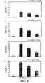
- FIG. 10 illustrates the phase ordering, alongside the improved scan efficiency of the PAWS technique, produces better images than the DVA technique in the same scan time. However, as the bin size is increased, particularly in the central region of k-space (c–d), the benefits of using phase ordering are reduced.
- FIG. 11 schematically illustrates a system of magnetic resonance imaging.
- PAWS Phase-ordering with Automatic Window Selection
- the initial position of the diaphragm is taken as the reference and all further diaphragm positions are given an index position which is the displacement from this reference.
- Each index position is allotted a region of k-space, hereafter called a “bin”, as shown in FIG. 1 .
- the k-space region is filled according to the direction of the arrows.
- Data acquisition for positions on the edges of k-space is straightforward, phase encode lines are acquired sequentially towards the centre of k-space. For positions which start in the centre of k-space, however, the data acquisition scheme is more complicated.
- Each diaphragm position can be used in one of a combination of 3 separate bins.
- the three possible combinations of bins which can complete k-space are: 2-3-4, 3-4-5 and 4-5-6. All three combinations are checked to determine which is closest to completion and this information is used to determine whether the right or left side of k-space is acquired. The side which has most unfilled k y lines remaining is acquired. This is demonstrated in FIG. 1 .
- the window nearest to completion at this moment in time is 4-5-6. As there are more unfilled phase encode lines remaining between 4–6 than 4–5, the phase encode line toward the diaphragm position 6 is acquired.
- Image acquisition is complete once the whole of k-space has been acquired by 3 contiguous bins. This is demonstrated in FIG. 2 .
- the final image is acquired in the shortest possible time and the phase encode lines have been ordered thus minimising motion artefacts.
- the final range of motion is only 3 mm as a bin size of 1 has been used with a navigator resolution of 1 mm.
- Scan time can further be reduced in two ways: the bin size can be increased, thus allowing more than one index position to map to each individual bin, or the navigator resolution can be decreased so that a wider range of positions map to the same index position.
- image quality may be compromised as the phase ordering within each individual bin is less well defined.
- FIG. 3 illustrates the final displacement graph for an image acquired with a bin size of 2 and a navigator resolution of 1 mm.
- the benefits of using phase ordering are reduced with an increased bin size or lower navigator resolution, within each individual bin the displacement between any phase encode lines is limited to the bin size. Therefore, although a bin size of 1 and a navigator resolution of 2 mm would produce a displacement graph as shown in FIG. 2 b , the range of motion in each bin is similar to that in FIG. 3 .
- a weighted bin scheme can be employed whereby an increased bin size is used for the two outer bins whilst the central bin size remains one.
- a typical displacement graph is shown in FIG. 4 .
- a bin size of 2 is used for the outer bins with a navigator resolution of 1 mm for all the bins which gives a window size of 5 mm.
- the PAWS technique was compared with the DVA.
- the DVA method allows a scan to be terminated after a specified time or when the desired range of motion has been achieved. Therefore the methods can be compared to see how long each takes to acquire an image in a specified acceptance window and how effective respiratory artefact reduction is after a defined time.
- respiratory profiles acquired previously from 15 subjects were fed into a simulation program which calculated the scan time and diaphragm displacement graph through k-space for each technique, as well as the shortest scan time possible for each trace with the required acceptance window.
- the DVA technique was used to construct an image in the same time as that taken by the PAWS technique.
- the displacement graphs through k-space produced by the simulation program were used to compile motion data sets.
- Profiles were taken through the images and, for image analysis, measurements were made of the peak signal intensity of the tube, the full width at half maximum (FWHM), the area surrounded by the pixels of the half maximum intensity (area at half maximum [AHM] and the total area (A).
- FWHM was used to measure blurring and (A-AHM) indicated the level of ghosting in the images.
- Table 1 shows the number of cardiac cycles required to complete a scan for PAWS and the DVA method using the respiratory traces when acquiring an image of 128 PE lines.
- the shortest scan time possible is also displayed.
- the average percentage difference from the shortest scan time using both a weighted bin and a larger bin size are also shown in Table 2.
- the PAWS approach achieves a shorter scan time with an average percentage difference of 4.6% and 4.7% respectively compared to 13.0% and 16.3% for the DVA approach.
- FIG. 5 demonstrates the importance of a navigator window selection and the implications for scan efficiency.
- a typical respiratory trace with the corresponding 3 mm acceptance window is shown.
- the PAWS technique (a) achieves optimal scan efficiency whilst the DVA technique (b) requires 47 extra cardiac cycles, a percentage difference of 18.1% from the optimal scan efficiency, to complete the scan.
- the two methods have opted for slightly different acceptance windows.
- the DVA method includes the extreme end expiratory position in the acceptance window whilst the PAWS technique discards this position, instead opting to shift the acceptance window by 1 mm to allow optimal scan efficiency.
- just a 1 mm shift has caused a large reduction in scan efficiency.
- FIG. 6 demonstrates the processes involved in selecting the final acceptance window.
- the DVA method finds that the most frequency diaphragm position is 287. The DVA technique will therefore attempt to narrow the range of motion around this position.
- the shortest scan time in this example is 260 cardiac cycles as this is the first point at which 128 diaphragm positions have been recorded within a 3 mm window.
- the PAWS technique detects that there are 3 contiguous positions which can be used to fill the whole of k-space and therefore terminates, using data in the range 287–289.
- the PAWS technique is also less efficient as the acceptance window is increased and the principal reason for this lies in the grouping of diaphragm positions when the bin size is greater than one.
- the initial diaphragm position which is recorded is set to index 0 and each successive diaphragm position is given an index relative to this.
- diaphragm positions are grouped together in what may eventually not be the most optimal way. This is demonstrated in FIG. 7 .
- the mot efficient scan time for the acquisition of 128 phase encode lines would have occurred after 190 cardiac cycles in the window 287–291.
- PAWS has grouped the diaphragm positions, 286 and 287 are paired together and the window 287–291 is not possible. The acquisition must therefore continue and completes after 217 cardiac cycles.
- this method is also grouping diaphragm positions, the difference being that the PAWS algorithm can now complete with the same window as that chosen by the simulation program when calculating the shortest scan time possible.
- the shortest scan time possible may change from one set of parameters to the next.
- the PAWS technique is more efficient given a single bin size, we feel that the lowest navigator resolution possible should be used.
- This technique also aided the DVA approach. In one particular case (subject 1) the DVA method selected a window around inspiration as the most frequency position occurred here.
- grouping navigator positions by way of reducing the resolution of the navigator allowed DVA to focus on a larger more frequent region and allowed the scan to terminate in a much shorter scan time with a saving of 203 cardiac cycles.
- FIG. 8 demonstrates the problems encountered when attempting to acquire data in a situation where the breathing pattern is extremely variable.
- the accumulated diaphragm position histograms (a) are shown alongside the differential histograms (b) and the corresponding breathing pattern is shown in FIG. 9 .
- This is an actual breathing pattern and demonstrates the inconsistent nature of breathing often observed during an acquisition.
- 256 views are acquired to demonstrate the changes in breathing and implications for scan efficiency and image quality during a long acquisition.
- diaphragm position 276 is the most frequent and, therefore, the DVA technique attempts to minimise motion around this position. However, during the next 100 cardiac cycles, this position only occurs twice as the breathing pattern has changed significantly.
- FIG. 9 also illustrates a problem of all techniques which use the frequency information to select the most suitable window.
- DVA and PAWS select a window which is towards inspiration (DVA: 274–278; PAWS: 270–274).
- inspiration DVA: 274–278; PAWS: 270–274.
- acquisitions made when the diaphragm is towards inspiration are more likely to suffer motion artefact as the diaphragm is moving with a greater velocity (12). Therefore, it is not only important to place the acceptance window around a frequency occurring diaphragm position, but this position should also preferably be around end-expiration.
- the PAWS technique is ideally suited to this requirement as data from all respiratory positions has been acquired.
- FIG. 10 demonstrates the advantages of using phase ordering with the PAWS technique.
- the phase ordered images have reduced ghosting and blurring.
- FIG. 10 b–d The mean and standard deviation for ghosting and blurring measurements for each method are shown in Table 3 for all 15 subjects.
- the PAWS method was more effective at reducing both blurring and ghosting artefacts if the motion in the centre of k-space was limited ( FIG. 10 a–b ).
- the advantages of using ordering are diminished ( FIG. 10 c–d ).
- the use of a weighted technique whereby the motion in the centre of k-space is restricted whilst the outer regions are acquired within larger acceptance ranges, allows an effective compromise between image quality and scan efficiency ( FIG. 10 b ).
- a method is introduced which is resistant to changes in breathing and allows images to be acquired in the shortest possible scan time with no requirement for operator interaction.
- the ability to integrate the use of phase ordering with a flexible window selection strategy further allows improvements in image quality.
- This method has proved to be effective both in improving scan efficiency and reducing respiratory motion artefacts in our in vitro studies. We believe this technique will aid in overcoming many of the current problems faced with navigator acceptance techniques, providing an ordering technique robust against changes in breathing which has previously not be possible.
- FIG. 11 schematically illustrates a magnetic resonance imaging system for use in imaging a heart 2 .
- the heart 2 is subject to periodic motion due to its beating.
- An ECG sensor detects when the heart 2 is at a predetermined point within its beat.
- the heart 2 is also subject to a period motion due to the patient breathing and motion of their diaphragm 6 .
- a magnetic resonance target 8 may be used by the MR imager 10 to track this motion. In this way, MR data may be recovered at a fixed point in the beat of the heart 2 at different points within the respiratory cycle and the sensed position of the target 8 used to direct the sampled data into an appropriate sample bin as discussed above.
Abstract
A magnetic imaging technique which is resistant to changes in breathing while allowing the use of phase ordering to provide effective motion artifact reduction in an optimal time. This is provided by apparatus for magnetic resonance imaging a target object subject to periodic motion, comprising a magnetic resonance imaging scanner for exciting said target object and recovering imaging data in k-space; a sensor for detecting a signal indicative of a position of said target object; classifying logic for classifying said at least one line of imaging data into one of a plurality of groups of lines of imaging date in dependence upon said position detected by said sensor as said target object was excited, each group of lines corresponding to one of a plurality of contiguous ranges of position and scan terminating logic for detecting when two or more groups of lines corresponding to contiguous ranges of position together containing a set of lines of imaging date spanning k-space from which an image can be derived.
Description
This application is the US national phase of international application PCT/GB00/03239 filed 18 Aug. 2000, which designated the US.
This invention relates to the field of magnetic resonance imaging. More particularly, this invention relates to techniques for increasing motion resistance in magnetic resonance imaging.
The development of navigator echo techniques has enabled the implementation of several algorithms to reduce motion effects from an image during acquisition (see references 1–11). Early gating techniques, based on the acceptance/rejection algorithm (see reference 2), were hindered by the loss in scan efficiency which resulted from the narrow acceptance windows required to effectively reduce artefacts and the variability of subjects respiration. The use of phase encode ordering (see references 8, 9) and weighting (see references 10, 11) have been shown to improve the image quality over conventional methods. The combination of phase ordering with a navigator acceptance window allowed larger acceptance windows to be used without compromising image quality whilst improving scan efficiency (see reference 9). Unfortunately, the effectiveness of all navigator acceptance window techniques is dependent on the choice of the acceptance window. Thus, during the scan, a change in the respiratory pattern may cause a window previously accepting data around the end-expiration position to be out of the new respiratory range. To overcome this limitation, more sophisticated gating techniques such as the Diminishing Variance Algorithm (DVA) have been suggested which adaptively select the most appropriate acceptance window depending on several factors such as the subjects' respiratory pattern, image data acquired so far, and scan time (see reference 4). The combination of DVA with a phase ordering or a weighting approach, although ideal, is not suited to changes in breathing patterns. The decision-taking is based upon a compromise between the repeated acquisition of profiles within an acceptable measuring time and termination of the scan because the achieved image quality is already close to the desired one (see reference 11). Although these techniques attempt to be more adaptable to changes in respiratory patterns the use of an acceptance window is inherent as a decision to accept or reject data must still be made. This is therefore prohibitive if the breathing pattern changes significantly during the acquisition as respiratory positions which were previously discarded are now desired and the previous rejection has resulted in a loss of scan efficiency. Although data can be acquired when the respiratory position is out of the required range, in case the diaphragm position changes during the scan, it is unpredictable how much will be useful when the acceptance window is moved. The use of a weighted acceptance window further complicates this.
The purpose of this invention is to seek to provide a technique which is resistant to changes in breathing whilst allowing the use of phase ordering to provide effective motion artefact reduction in a short time. Each position is regarded as equally relevant to the final image. The operator simply decides on the size of the acceptance window.
Viewed from one aspect the invention provides apparatus for magnetic resonance imaging a target object, said apparatus comprising:
-
- a magnetic resonance imaging scanner for exciting said target object and recovering at least one line of imaging data in k-space;
- a first sensor for detecting a signal indicative of a position of said target object relative to said magnetic resonance imaging scanner;
- classifying logic for classifying said at least one line of imaging data into one of a plurality of groups of lines of imaging data in dependence upon said position detected by said second sensor as said target object was excited, each group of lines corresponding to one of a plurality of contiguous ranges of position relative to said magnetic resonance imaging scanner; and
- scan terminating logic for detecting when two or more groups of lines corresponding to contiguous ranges of position together containing a set of lines of imaging data spanning k-space from which an image can be derived and terminating data acquisition.
It will be appreciated that the first sensor may be an ECG sensor and the second sensor may be an MR sensor detecting diaphragm position.
Various other features and aspects of the invention are set out in the appended claims.
Embodiments of the invention will now be described, by way of example only, with reference to the accompanying drawings in which:
The proposed technique, Phase-ordering with Automatic Window Selection (PAWS), uses a multi-level approach where no acceptance window is specified. Instead, the initial position of the diaphragm is taken as the reference and all further diaphragm positions are given an index position which is the displacement from this reference. Each index position is allotted a region of k-space, hereafter called a “bin”, as shown in FIG. 1 . The k-space region is filled according to the direction of the arrows. Data acquisition for positions on the edges of k-space is straightforward, phase encode lines are acquired sequentially towards the centre of k-space. For positions which start in the centre of k-space, however, the data acquisition scheme is more complicated. Each diaphragm position can be used in one of a combination of 3 separate bins. For example, for index number 4, the three possible combinations of bins which can complete k-space are: 2-3-4, 3-4-5 and 4-5-6. All three combinations are checked to determine which is closest to completion and this information is used to determine whether the right or left side of k-space is acquired. The side which has most unfilled ky lines remaining is acquired. This is demonstrated in FIG. 1 . For the case where the diaphragm is currently at position 4, the window nearest to completion at this moment in time is 4-5-6. As there are more unfilled phase encode lines remaining between 4–6 than 4–5, the phase encode line toward the diaphragm position 6 is acquired. Image acquisition is complete once the whole of k-space has been acquired by 3 contiguous bins. This is demonstrated in FIG. 2 . The final image is acquired in the shortest possible time and the phase encode lines have been ordered thus minimising motion artefacts. In this example, the final range of motion is only 3 mm as a bin size of 1 has been used with a navigator resolution of 1 mm.
Scan time can further be reduced in two ways: the bin size can be increased, thus allowing more than one index position to map to each individual bin, or the navigator resolution can be decreased so that a wider range of positions map to the same index position. However, image quality may be compromised as the phase ordering within each individual bin is less well defined. FIG. 3 illustrates the final displacement graph for an image acquired with a bin size of 2 and a navigator resolution of 1 mm. Although the benefits of using phase ordering are reduced with an increased bin size or lower navigator resolution, within each individual bin the displacement between any phase encode lines is limited to the bin size. Therefore, although a bin size of 1 and a navigator resolution of 2 mm would produce a displacement graph as shown in FIG. 2 b, the range of motion in each bin is similar to that in FIG. 3 .
To limit motion in the centre of k-space when the bin size is greater than one, a weighted bin scheme can be employed whereby an increased bin size is used for the two outer bins whilst the central bin size remains one. A typical displacement graph is shown in FIG. 4 . In this example, a bin size of 2 is used for the outer bins with a navigator resolution of 1 mm for all the bins which gives a window size of 5 mm.
In Vitro Studies
Studies were performed with a whole-body 0.5 T magnet with a reduced diameter (53 cm I.D.) gradient set giving 20 mT/m maximum gradient strength, and a slew rate of 60 mT/m/ms. An MR imaging console (Surrey Medical Imaging Systems) with additional hardware and software was used to generate and drive the gradient and radio-frequency waveforms and to receive and reconstruct the image data. The ordering method was implemented for a fat-suppressed 3D velocity compensated gradient-echo pulse sequence (Te=6 MS). 8 kZ lines were acquired with a TR of 12 ms, resulting in a total acquisition period of 96 ms. Each Ky was acquired after an interval of 800 ms. 256 Ky lines were acquired with a FOV of 300 mm and a slab thickness of 20 mm resulting in a voxel size of 1.2 mm×1.2 mm×2.5 mm.
To compare the effects of the different ordering methods in vitro, complete data sets were acquired of a 4 mm diameter tube. Multiple data sets were acquired with the tube moved by steps of 1 mm between each. The total range of positions was 10 mm. This allowed simulated data sets to be constructed given a series of motion measurements by selecting appropriate ky lines from each data set. The tube was filled with copper sulphate solution (0.5 mM) and curved to represent a coronary artery.
The PAWS technique was compared with the DVA. The DVA method allows a scan to be terminated after a specified time or when the desired range of motion has been achieved. Therefore the methods can be compared to see how long each takes to acquire an image in a specified acceptance window and how effective respiratory artefact reduction is after a defined time.
The techniques were compared with acceptance window sizes of 3 mm (PAWS: bin size=1), 6 mm (PAWS: bin size=2) and 5 mm (PAWS: bin size=2 for outer bins, bin size=1 for central bin). A navigator resolution of 1 mm was used in all cases.
For scan efficiency, respiratory profiles acquired previously from 15 subjects were fed into a simulation program which calculated the scan time and diaphragm displacement graph through k-space for each technique, as well as the shortest scan time possible for each trace with the required acceptance window.
For image quality, the DVA technique was used to construct an image in the same time as that taken by the PAWS technique. The displacement graphs through k-space produced by the simulation program were used to compile motion data sets. Profiles were taken through the images and, for image analysis, measurements were made of the peak signal intensity of the tube, the full width at half maximum (FWHM), the area surrounded by the pixels of the half maximum intensity (area at half maximum [AHM] and the total area (A). FWHM was used to measure blurring and (A-AHM) indicated the level of ghosting in the images.
Table 1 (see later) shows the number of cardiac cycles required to complete a scan for PAWS and the DVA method using the respiratory traces when acquiring an image of 128 PE lines. The shortest scan time possible is also displayed. The average percentage difference from the shortest scan time was only 0.5% (STD=0.7) for the PAWS approach in comparison to 15.5% (STD=26.3) for the DVA approach. The average percentage difference from the shortest scan time using both a weighted bin and a larger bin size are also shown in Table 2. Again, the PAWS approach achieves a shorter scan time with an average percentage difference of 4.6% and 4.7% respectively compared to 13.0% and 16.3% for the DVA approach.
This example highlights a drawback in the DVA technique. As it attempts to minimise motion around the most frequency position, it is assuming that this position will lie in the centre of the acceptance range. However, if this position is at end expiration, for example, which occurs often, then it is likely that it will occur towards one end of the acceptance window. Therefore, positions further away from end expiration, which should be included, are discarded as they are further from the maximum than other less frequency positions. This is more likely to occur with larger acceptance windows and could be a factor in the reduced efficiency of the DVA technique when the window size is increased.
The PAWS technique is also less efficient as the acceptance window is increased and the principal reason for this lies in the grouping of diaphragm positions when the bin size is greater than one. The initial diaphragm position which is recorded is set to index 0 and each successive diaphragm position is given an index relative to this. In cases where the bin size is greater than one, diaphragm positions are grouped together in what may eventually not be the most optimal way. This is demonstrated in FIG. 7 . For a 5 mm window, the mot efficient scan time for the acquisition of 128 phase encode lines would have occurred after 190 cardiac cycles in the window 287–291. However, because of the way PAWS has grouped the diaphragm positions, 286 and 287 are paired together and the window 287–291 is not possible. The acquisition must therefore continue and completes after 217 cardiac cycles.
If a window combination is therefore unavailable to PAWS, there is potential for loss of scan efficiency given the scan parameters. However, as we mentioned earlier, there are two possible ways of achieving the same window sizes: by altering the bin size and by altering the navigator resolution. Therefore, if we are using a bin size of 2 and a navigator resolution of 1 mm, PAWS may not perform in the shortest time possible as the most efficient window is not available. If these parameters are changed however, and a bin size of 1 is used with a lower navigator resolution of 2 mm, the window size remains the same but PAWS can now complete in the shortest time possible for the scan given the parameters. The use of a reduced navigator resolution for the 6 mm window reduced the average difference from the shortest scan time from 4.7% to 2.6%. It is important to note however that although an improvement was found by using the reduced navigator resolution as opposed to a larger bin size, this method is also grouping diaphragm positions, the difference being that the PAWS algorithm can now complete with the same window as that chosen by the simulation program when calculating the shortest scan time possible. Depending on the grouping, the shortest scan time possible may change from one set of parameters to the next. However, given the infinite variations of possible parameters, as the PAWS technique is more efficient given a single bin size, we feel that the lowest navigator resolution possible should be used. This technique also aided the DVA approach. In one particular case (subject 1) the DVA method selected a window around inspiration as the most frequency position occurred here. However, grouping navigator positions by way of reducing the resolution of the navigator allowed DVA to focus on a larger more frequent region and allowed the scan to terminate in a much shorter scan time with a saving of 203 cardiac cycles.
It is also important to note that the window, [c], which has been chosen to be the most desirable in terms of image quality in FIG. 9 is unlikely to have been selected were a decision to be formed after either an initial period of monitoring the diaphragm position or after analysis of scan efficiency as many of the positions occur much later in the scan and many do not occur even in the initial 256 cardiac cycles. Instead, it is only in retrospect, having weighed up both scan efficiency and image quality costs, that this window is selected. This is the principal benefit of the PAWS technique. It is possible during data acquisition to analyse the subject's breathing pattern and the progress of acquisition for any window. As the order of data acquisition is the same, regardless of the final window we may choose, it is possible to make an infinite number of alterations to the final window with no loss in scan efficiency. This is extremely useful in situations where a window placed around end-expiration is now acquiring data in inspiration.
As well as the desire to acquire images from around end-expiration, there is also a preference as to the final ordering of the phase encoding lines. In our previous studies into the effects of different ordering patterns on coronary artery imaging, we found that the use of an asymmetric ordering pattern produced considerably better images than the use of a symmetric ordering pattern (13). Therefore, if the initial data set which completes produces a symmetric ordering pattern, we could balance up the expected gains in image quality and the extra time required to complete a more suitable window resulting in an asymmetric pattern. It is important to note, however, that both ordering patterns produced better images than those acquired without the use of ordering.
As the PAWS and DVA techniques select a window primarily on the basis of scan efficiency, it is possible that over successive acquisitions the position of the window could change. This could lead to misregistration problems between images. However, it could be possible to combine the techniques with slab following to ensure a more consistent window for all images. Therefore, after the initial acquisition, the centre of the window is used as a reference position. We could use slab following to ensure that all further acquisitions occur at the same point. The use of phase ordering could also help overcome the small phase errors and pseudo-motion ghosting from stationary tissues which result from the use of slab following by ensuring that the relative errors between successive phase encode lines is minimal.
Once the appropriate window has been selected from the multiple windows which have been acquired, several partially complete data sets remain. It may therefore be possible to use a combination of data averaging and post-processing to utilise more of the data to further improve image quality. Also, more than one data set could be acquired in a single acquisition.
A method is introduced which is resistant to changes in breathing and allows images to be acquired in the shortest possible scan time with no requirement for operator interaction. The ability to integrate the use of phase ordering with a flexible window selection strategy further allows improvements in image quality. This method has proved to be effective both in improving scan efficiency and reducing respiratory motion artefacts in our in vitro studies. We believe this technique will aid in overcoming many of the current problems faced with navigator acceptance techniques, providing an ordering technique robust against changes in breathing which has previously not be possible.
It will be appreciated that the technique of the present invention may be conveniently embodied as part of software running on a general purpose computer for analysing the data signals recovered from the MR imaging.
- 1. Y. L. Liu, S. J. Riederer, P. J. Rossman, R. C. Grimm, J. P. Debbins, R. L. Ehman, A monitoring, feedback, and triggering system for reproducible breath-hold MR imaging. Magn. Reson. Med. 30, 507–511 (1993).
- 2. T. S. Sachs, C. H. Meyer, B. S. Hu, J. Kohli, D. G. Nishimura, A. Macovski, Real-time motion detection in spiral MRI using navigators. Magn. Reson. Med. 32, 639–645 (1994).
- 3. Y. Wang, P. J. Rossman, R. C. Grimm, S. J. Riederer, R. L. Ehman, Navigator-echo based real-time respiratory gating and triggering for reduction of respiration effects in three-dimensional coronary MR angiography. Radiology 198, 55–60 (1996).
- 4. T. S. Sachs, C. H. Meyer, P. Irarrazabal, B. S. Hu, D. G. Nishimura, A. Macovski, The diminishing variance algorithm for real-time reduction of motion artifacts in MRI. Magn. Reson. Med. 34, 412–429 (1995).
- 5. D. Li, C. B. Paschal, E. M. Haacke, L. P. Adler, Coronary arteries: three-dimensional MR imaging with fat saturation and magnetization transfer contrast. Radiology 187, 401406 (1993).
- 6. M. B. M. Hofman, C. B. Paschal, D. Li, E. M. Haacke, A. C. van Rossum, M. Sprenger, MRI of coronary arteries: 2D breath-hold vs 3D respiratory-gated acquisition. J. Comput. Assist. Tomogr. 19, 56–62 (1995).
- 7. D. Li. S. Kaushikklar, E. M. Haacke, P. K. Woodard, P. J. Dhawale, R. M. Kroeker, G. Laub, Y. Kuginuki, F. R. Gutierrez, Coronary arteries: three dimensional MR imaging with retrospective respiratory gating. Radiology 201. 857–363 (1996).
- 8. P. Jhooti, F. Wiesmann, A. M. Taylor, P. D. Gatehouse, G. Z. Yang, J. Keegan, D. Pennell, D. N. Firmin, Hybrid ordered phase encoding: an improved approach for respiratory artefact reduction, J. Magn. Reson.
Imaging 8, 968–980 (1998). - 9. P. Jhooti, J. Keegan, P. D. Gatehouse, S. Collins, A. Rowe, A. M. Taylor, D. N. Firmin; 3D Coronary Artery Imaging with Phase Reordering for Improved Scan Efficiency. Magn. Reson. Med. 41, 555–562 (1999).
- 10. R. Sinkus, P. Börnert, Real-time reduction of motion artefacts using k-space weighting, in “Proc., ISMRM, 5th Annual Meeting, Vancouver, 1997,” p. 1894.
- 11. M. Weiger, P. Börnert, R. Proksa, T. Schäffter, A. Haase, Motion-Adapted Gating Based on k-Space Weighting for Reduction of Respiratory Motion Artifacts, Magn. Resn. Med. 38, 322–333 (1997).
- 12. A. M. Taylor, P. Jhooti, F. Wiesmann, J. Keegan, D. N. Firmin, D. J. Pennell, MR navigator-echo monitoring of temporal changes in diaphragm position: implications for MR coronary angiography. J. Magn. Reson.
Imaging 7, 629–636 (1997). - 13. P. Jhooti, P. D. Gatehouse, J. Keegan, D. N. Firmin, Phase ordering techniques: implications for coronary artery imaging. Submitted for publication 1999
Tables
| TABLE 1 |
| Number of cardiac cycles required to acquire 128 phase |
| encode lines within a 3 mm acceptance window. |
| Least Cardiac | DVA Cardiac | PAWS Cardiac | ||
| Cycles Required | Cycles | Cycles | ||
| 1 | 559 | 1103 | 565 | ||
| 2 | 507 | 671 | 507 | ||
| 3 | 765 | 765 | 765 | ||
| 4 | 260 | 307 | 260 | ||
| 5 | 300 | 300 | 300 | ||
| 6 | 238 | 268 | 239 | ||
| 7 | 290 | 290 | 291 | ||
| 8 | 273 | 273 | 273 | ||
| 9 | 227 | 227 | 230 | ||
| 10 | 515 | 520 | 515 | ||
| 11 | 467 | 467 | 467 | ||
| 12 | 451 | 497 | 453 | ||
| 13 | 358 | 420 | 366 | ||
| 14 | 541 | 774 | 547 | ||
| 15 | 364 | 364 | 364 | ||
| TABLE 2 |
| Percentage difference between cardiac cycles required to acquire |
| 128 phase encode lines using the DVA and PAWS technique |
| compared to the optimum scan time. |
| Acceptance Window | DVA | PAWS | ||
| 3 (Bin 1-1-1) | 15.5% (STD 26.3) | 0.5% (STD 0.7) | ||
| 5 (Bin 2-1-2) | 13.0% (STD 17.9) | 4.6% (STD 4.8) | ||
| 6 (Bin 2-2-2) | 16.3% (STD 19.1) | 4.7% (STD 4.6) | ||
| TABLE 3a |
| Mean blurring measurements for tube using traces acquired |
| from 15 subjects using PAWS and DVA. |
| Acceptance Window | DVA | PAWS | ||
| 3 (Bin 1-1-1) | 4.4% (STD 0.4) | 4.2% (STD 0.5) | ||
| 5 (Bin 2-1-2) | 4.7% (STD 0.5) | 5.3% (STD 1.2) | ||
| 6 (Bin 2-2-2) | 5.1% (STD 0.7) | 5.0% (STD 0.8) | ||
| TABLE 3b |
| Mean Ghosting measurements for tube using traces acquired |
| from 15 subjects using PAWS and DVA. |
| Acceptance Window | DVA | PAWS |
| 3 (Bin 1-1-1) | 434.7% (STD 44.8) | 330.9% (STD 12.8) |
| 5 (Bin 2-1-2) | 423.3% (STD 61.5) | 371.6% (STD 28.8) |
| 6 (Bin 2-2-2) | 458.6% (STD 67.2) | 438.9% (STD 65.8) |
Claims (11)
1. Apparatus for magnetic resonance imaging a target object, said apparatus comprising:
a magnetic resonance imaging scanner for exciting said target object and recovering at least one line of imaging data in k-space;
a first sensor for detecting a signal indicative of a position of said target object relative to said magnetic resonance imaging scanner;
classifying logic for classifying said at least one line of imaging data into one of a plurality of groups of lines of imaging data in dependence upon said position detected by said first sensor as said target object was excited, each group of lines corresponding to one of a plurality of contiguous ranges of position relative to said magnetic resonance imaging scanner; and
scan terminating logic for detecting when two or more groups of lines corresponding to contiguous ranges of position together contain a set of lines of imaging data spanning k-space from which an image can be derived and terminating data acquisition.
2. Apparatus as claimed in claim 1 , wherein said target object is subject to periodic motion, further comprising a second sensor for detecting when said target object is at a predetermined state within said periodic motion, and wherein said magnetic resonance imaging scanner is responsive to said second sensor detecting said target object is at said predetermined state to trigger said excitation.
3. Apparatus as claimed in claim 1 , wherein said target object is an in vivo organ.
4. Apparatus as claimed in claim 3 , wherein said target object is a heart.
5. Apparatus as claimed in claim 4 , wherein said second sensor is an ECG sensor.
6. Apparatus as claimed in claim 1 , wherein said first sensor detects changes in position of said target object due to respiration.
7. Apparatus as claimed in claim 6 , wherein said first sensor is a magnetic resonance sensor for sensing diaphragm position.
8. Apparatus as claimed in claim 1 , wherein when a line of imaging data can be selected to be acquired on either side of k-space corresponding to two different groups of lines, said line is acquired in that group closest to forming one of two or more groups of lines corresponding to contiguous ranges of position together containing a set of lines of imaging data spanning k-space from which an image can be derived.
9. Apparatus as claimed in claim 1 , wherein at least one group of lines close to a central position detected by said first sensor corresponds to a smaller range of positions than a group of lines further from said central position.
10. A method of magnetic resonance imaging a target object, said method comprising the steps of:
exciting said target object and recovering at least one line of imaging data in k-space using a magnetic resonance imaging scanner;
detecting a signal indicative of a position of said target object relative to said magnetic resonance imaging scanner;
classifying said at least one line of imaging data into one of a plurality of groups of lines of imaging data in dependence upon said position detected as said target object was excited, each group of lines corresponding to one of a plurality of contiguous ranges of position relative to said magnetic resonance imaging scanner; and
detecting when two or more groups of lines corresponding to contiguous ranges of position together containing a set of lines of imaging data spanning k-space from which an image can be derived and terminating data acquisition.
11. A computer program medium storing a computer program for controlling a computer coupled apparatus for magnetic resonance imaging a target object, said apparatus comprising:
a magnetic resonance imaging scanner for exciting said target object and recovering at least one line of imaging data in k-space;
a first sensor for detecting a signal indicative of a position of said target object relative to said magnetic resonance imaging scanner; said computer program serving to control said computer to perform the steps of:
classifying said at least one line of imaging data into one of a plurality of groups of lines of imaging data in dependence upon said position detected as said target object was excited, each group of lines corresponding to one of a plurality of contiguous ranges of position relative to said magnetic resonance imaging scanner; and
detecting when two or more groups of lines corresponding to contiguous ranges of position together containing a set of lines of imaging data spanning k-space from which an image can be derived and terminating data acquisition.
Applications Claiming Priority (2)
| Application Number | Priority Date | Filing Date | Title |
|---|---|---|---|
| GBGB9919821.0A GB9919821D0 (en) | 1999-08-20 | 1999-08-20 | Phase ordering with automatic window selection (PAWS):A novel motion resistant technique for 3D coronary imaging |
| PCT/GB2000/003239 WO2001014901A1 (en) | 1999-08-20 | 2000-08-18 | Phase ordering with automatic window selection (paws) for motion resistant mri |
Publications (1)
| Publication Number | Publication Date |
|---|---|
| US7039451B1 true US7039451B1 (en) | 2006-05-02 |
Family
ID=10859569
Family Applications (1)
| Application Number | Title | Priority Date | Filing Date |
|---|---|---|---|
| US10/049,899 Expired - Fee Related US7039451B1 (en) | 1999-08-20 | 2000-08-18 | Phase ordering with automatic window selection (PAWS) for motion resistant MRI |
Country Status (5)
| Country | Link |
|---|---|
| US (1) | US7039451B1 (en) |
| EP (1) | EP1204881A1 (en) |
| AU (1) | AU6710700A (en) |
| GB (1) | GB9919821D0 (en) |
| WO (1) | WO2001014901A1 (en) |
Cited By (14)
| Publication number | Priority date | Publication date | Assignee | Title |
|---|---|---|---|---|
| US20090140734A1 (en) * | 2003-11-13 | 2009-06-04 | Koninklijke Philips Electronics Nv | Readout ordering in collection of radial magnetic resonance imaging data |
| US20090253980A1 (en) * | 2008-04-08 | 2009-10-08 | General Electric Company | Method and apparatus for determining the effectiveness of an image transformation process |
| US20090270719A1 (en) * | 2008-04-23 | 2009-10-29 | Mitsuharu Miyoshi | Mri apparatus |
| DE102012206547A1 (en) | 2012-04-20 | 2013-10-24 | Siemens Aktiengesellschaft | Acquisition of a measurement dataset of a breathing examination subject by means of magnetic resonance technique |
| DE102012206555A1 (en) | 2012-04-20 | 2013-10-24 | Siemens Aktiengesellschaft | Method for acquiring a measurement data set of a breathing examination subject by means of magnetic resonance technique, magnetic resonance system, computer program and electronically readable data carriers |
| DE102012206550A1 (en) | 2012-04-20 | 2013-10-24 | Siemens Aktiengesellschaft | Method for acquiring a measurement data set of a breathing examination subject by means of magnetic resonance technique, magnetic resonance system, computer program and electronically readable data carriers |
| DE102012206578A1 (en) | 2012-04-20 | 2013-10-24 | Siemens Aktiengesellschaft | Method for acquiring a measurement data set of a breathing examination subject by means of magnetic resonance technique, magnetic resonance system, computer program and electronically readable data carriers |
| US20130338486A1 (en) * | 2012-06-14 | 2013-12-19 | Yu Qing Huang | Diffusion tensor magnetic resonance imaging method |
| US20150238149A1 (en) * | 2013-07-10 | 2015-08-27 | Kabushiki Kaisha Toshiba | Magnetic resonance imaging apparatus |
| CN107451389A (en) * | 2016-04-06 | 2017-12-08 | 西门子保健有限责任公司 | Method for illustrating medical image data |
| EP3470869A1 (en) | 2017-10-10 | 2019-04-17 | Koninklijke Philips N.V. | Mr imaging using motion-dependent radial or spiral k-space sampling |
| EP3517988A1 (en) | 2018-01-29 | 2019-07-31 | Koninklijke Philips N.V. | Mr imaging using a stack-of-stars acquisition with intrinsic motion correction |
| EP3640662A1 (en) | 2018-10-16 | 2020-04-22 | Koninklijke Philips N.V. | Magnetic resonance imaging using motion-compensated image reconstruction |
| EP3709042A1 (en) | 2019-03-14 | 2020-09-16 | Koninklijke Philips N.V. | Mr imaging using a 3d radial or spiral acquisition with soft motion gating |
Families Citing this family (5)
| Publication number | Priority date | Publication date | Assignee | Title |
|---|---|---|---|---|
| GB2424075B (en) * | 2005-03-11 | 2007-07-04 | Royal Brompton & Harefield Nhs | MRI imaging |
| US7570052B2 (en) | 2005-03-11 | 2009-08-04 | Royal Brompton & Harefield Nhs Trust | MRI imaging of an object in cyclic motion |
| GB2425604B (en) | 2005-04-30 | 2007-04-04 | Royal Brompton & Harefield Nhs | Capture of MRI images |
| US10327666B2 (en) | 2014-12-10 | 2019-06-25 | Elekta, Inc. | Magnetic resonance projection imaging |
| CN113100741B (en) * | 2020-01-13 | 2024-02-27 | 上海联影医疗科技股份有限公司 | Magnetic resonance scanning method, equipment and storage medium |
Citations (7)
| Publication number | Priority date | Publication date | Assignee | Title |
|---|---|---|---|---|
| US4663591A (en) * | 1985-08-16 | 1987-05-05 | General Electric Company | Method for reducing image artifacts due to periodic signal variations in NMR imaging |
| US4930508A (en) * | 1987-04-10 | 1990-06-05 | Yair Shimoni | Reducing respiratory motion artifacts in nuclear magnetic resonance images |
| US5035244A (en) * | 1988-02-23 | 1991-07-30 | Elscint Ltd. | Motion artifact minimization |
| US5427101A (en) * | 1994-08-04 | 1995-06-27 | Board Of Trustees Of The Leland Stanford Junior University | Diminishing variance process for real-time reduction of motion artifacts in MRI |
| US5842989A (en) * | 1996-03-21 | 1998-12-01 | Elscint, Ltd. | Artifact reduction in magnetic resonance angiographic images |
| US6044290A (en) * | 1997-04-11 | 2000-03-28 | Wisconsin Alumni Research Foundation | Time-resolved digital subtraction magnetic resonance angiography using echo-planar imaging |
| US6353752B1 (en) * | 1999-05-14 | 2002-03-05 | Board Of Trustees Of The Leland Standford Junior University | Reduced field-of-view method for cine magnetic resonance imaging |
-
1999
- 1999-08-20 GB GBGB9919821.0A patent/GB9919821D0/en not_active Ceased
-
2000
- 2000-08-18 EP EP00954749A patent/EP1204881A1/en not_active Withdrawn
- 2000-08-18 AU AU67107/00A patent/AU6710700A/en not_active Abandoned
- 2000-08-18 US US10/049,899 patent/US7039451B1/en not_active Expired - Fee Related
- 2000-08-18 WO PCT/GB2000/003239 patent/WO2001014901A1/en not_active Application Discontinuation
Patent Citations (8)
| Publication number | Priority date | Publication date | Assignee | Title |
|---|---|---|---|---|
| US4663591A (en) * | 1985-08-16 | 1987-05-05 | General Electric Company | Method for reducing image artifacts due to periodic signal variations in NMR imaging |
| US4720678A (en) * | 1985-08-16 | 1988-01-19 | General Electric Company | Apparatus and method for evenly distributing events over a periodic phenomenon |
| US4930508A (en) * | 1987-04-10 | 1990-06-05 | Yair Shimoni | Reducing respiratory motion artifacts in nuclear magnetic resonance images |
| US5035244A (en) * | 1988-02-23 | 1991-07-30 | Elscint Ltd. | Motion artifact minimization |
| US5427101A (en) * | 1994-08-04 | 1995-06-27 | Board Of Trustees Of The Leland Stanford Junior University | Diminishing variance process for real-time reduction of motion artifacts in MRI |
| US5842989A (en) * | 1996-03-21 | 1998-12-01 | Elscint, Ltd. | Artifact reduction in magnetic resonance angiographic images |
| US6044290A (en) * | 1997-04-11 | 2000-03-28 | Wisconsin Alumni Research Foundation | Time-resolved digital subtraction magnetic resonance angiography using echo-planar imaging |
| US6353752B1 (en) * | 1999-05-14 | 2002-03-05 | Board Of Trustees Of The Leland Standford Junior University | Reduced field-of-view method for cine magnetic resonance imaging |
Non-Patent Citations (3)
| Title |
|---|
| P. Jhooti et al; "3D Coronary Artery Imaging with Phase Reordering for Improved Scan Efficiency"; Magnetic Resonance in Medicine; vol. 41, 1999, pp. 555-562, XP002149700. |
| Sinkus R et al; "Motion Pattern Adapted Real-Time Respiratory Gating"; Magnetic Resonance in Medicine, US, Academic Press, DULUTH, MN., vol. 41, No. 1, 1999, pp. 148-155, XP000799744. |
| Weiger M et al.; "Motion-Adapted Gating Based on K-Space Weighting for Reduction of Respiratory Motion Artifacts"; Magnetic Resonance in Medicine, US, Academic Press, DULUTH, MN,. vol. 38, No. 2, Aug. 1, 1997, pp. 322-333, XP000695508. |
Cited By (32)
| Publication number | Priority date | Publication date | Assignee | Title |
|---|---|---|---|---|
| US20090140734A1 (en) * | 2003-11-13 | 2009-06-04 | Koninklijke Philips Electronics Nv | Readout ordering in collection of radial magnetic resonance imaging data |
| US20090253980A1 (en) * | 2008-04-08 | 2009-10-08 | General Electric Company | Method and apparatus for determining the effectiveness of an image transformation process |
| US8131044B2 (en) * | 2008-04-08 | 2012-03-06 | General Electric Company | Method and apparatus for determining the effectiveness of an image transformation process |
| US9201130B2 (en) | 2008-04-23 | 2015-12-01 | General Electric Company | MRI apparatus for imaging body fluids by suppressing the background tissues |
| US20090270719A1 (en) * | 2008-04-23 | 2009-10-29 | Mitsuharu Miyoshi | Mri apparatus |
| US9271662B2 (en) | 2012-04-20 | 2016-03-01 | Siemens Aktiengesellschaft | Magnetic resonance method and apparatus for obtaining a set of measured data relating to a breathing object of interest |
| US9138162B2 (en) | 2012-04-20 | 2015-09-22 | Siemens Aktiengesellschaft | Magnetic resonance method and apparatus for obtaining a set of measured data relating to a breathing object of interest |
| DE102012206578A1 (en) | 2012-04-20 | 2013-10-24 | Siemens Aktiengesellschaft | Method for acquiring a measurement data set of a breathing examination subject by means of magnetic resonance technique, magnetic resonance system, computer program and electronically readable data carriers |
| CN103371820A (en) * | 2012-04-20 | 2013-10-30 | 西门子公司 | Magnetic resonance method and apparatus for obtaining a set of measured data relating to a breathing object of interest |
| KR20130118827A (en) * | 2012-04-20 | 2013-10-30 | 지멘스 악티엔게젤샤프트 | Method for the acquisition of a measurement data set of a respirating examination subject by means of magnetic resonance technology, a magnetic resonance apparatus, computer programs and data mediums that can be read electronically |
| DE102012206578B4 (en) | 2012-04-20 | 2023-11-02 | Siemens Healthcare Gmbh | Method for acquiring a measurement data set of a breathing object to be examined using magnetic resonance technology, magnetic resonance system, computer program and electronically readable data carrier |
| DE102012206550A1 (en) | 2012-04-20 | 2013-10-24 | Siemens Aktiengesellschaft | Method for acquiring a measurement data set of a breathing examination subject by means of magnetic resonance technique, magnetic resonance system, computer program and electronically readable data carriers |
| DE102012206555B4 (en) | 2012-04-20 | 2023-08-03 | Siemens Healthcare Gmbh | Method for acquiring a measurement data set of a breathing examination subject using magnetic resonance technology, magnetic resonance system, computer program and electronically readable data carrier |
| DE102012206555A1 (en) | 2012-04-20 | 2013-10-24 | Siemens Aktiengesellschaft | Method for acquiring a measurement data set of a breathing examination subject by means of magnetic resonance technique, magnetic resonance system, computer program and electronically readable data carriers |
| CN103371820B (en) * | 2012-04-20 | 2016-02-03 | 西门子公司 | By the method for the measurement data set of the check object of mr techniques collection breathing |
| US9261575B2 (en) | 2012-04-20 | 2016-02-16 | Siemens Aktiengesellschaft | Magnetic resonance method and apparatus for obtaining a set of measured data relating to a breathing object of interest |
| DE102012206547A1 (en) | 2012-04-20 | 2013-10-24 | Siemens Aktiengesellschaft | Acquisition of a measurement dataset of a breathing examination subject by means of magnetic resonance technique |
| US9345437B2 (en) | 2012-04-20 | 2016-05-24 | Siemens Aktiengesellschaft | Method for obtaining a set of measured data relating to a breathing object of interest by using magnetic resonance technology, magnetic resonance system, computer program, and electronically readable data storage medium |
| US20130338486A1 (en) * | 2012-06-14 | 2013-12-19 | Yu Qing Huang | Diffusion tensor magnetic resonance imaging method |
| US20150238149A1 (en) * | 2013-07-10 | 2015-08-27 | Kabushiki Kaisha Toshiba | Magnetic resonance imaging apparatus |
| CN107451389A (en) * | 2016-04-06 | 2017-12-08 | 西门子保健有限责任公司 | Method for illustrating medical image data |
| US11269037B2 (en) | 2017-10-10 | 2022-03-08 | Koninklijke Philips N.V. | MR imaging using motion-dependent radial or spiral k-space sampling |
| WO2019072719A1 (en) | 2017-10-10 | 2019-04-18 | Koninklijke Philips N.V. | Mr imaging using motion-dependent radial or spiral k-space sampling |
| EP3470869A1 (en) | 2017-10-10 | 2019-04-17 | Koninklijke Philips N.V. | Mr imaging using motion-dependent radial or spiral k-space sampling |
| EP3517988A1 (en) | 2018-01-29 | 2019-07-31 | Koninklijke Philips N.V. | Mr imaging using a stack-of-stars acquisition with intrinsic motion correction |
| WO2019145527A1 (en) | 2018-01-29 | 2019-08-01 | Koninklijke Philips N.V. | Mr imaging using a stack-of-stars acquisition with intrinsic motion correction |
| EP3640662A1 (en) | 2018-10-16 | 2020-04-22 | Koninklijke Philips N.V. | Magnetic resonance imaging using motion-compensated image reconstruction |
| WO2020078907A1 (en) | 2018-10-16 | 2020-04-23 | Koninklijke Philips N.V. | Magnetic resonance imaging using motion-compensated image reconstruction |
| DE112019005169T5 (en) | 2018-10-16 | 2021-07-29 | Koninklijke Philips N.V. | MAGNETIC RESONANCE TOMOGRAPHY WITH MOTION COMPENSATED IMAGE RECONSTRUCTION |
| US11543482B2 (en) | 2018-10-16 | 2023-01-03 | Koninklijke Philips N.V. | Magnetic resonance imaging using motion-compensated image reconstruction |
| EP3709042A1 (en) | 2019-03-14 | 2020-09-16 | Koninklijke Philips N.V. | Mr imaging using a 3d radial or spiral acquisition with soft motion gating |
| WO2020183000A1 (en) | 2019-03-14 | 2020-09-17 | Koninklijke Philips N.V. | Mr imaging using a 3d radial or spiral acquisition with soft motion gating |
Also Published As
| Publication number | Publication date |
|---|---|
| GB9919821D0 (en) | 1999-10-27 |
| WO2001014901A1 (en) | 2001-03-01 |
| EP1204881A1 (en) | 2002-05-15 |
| AU6710700A (en) | 2001-03-19 |
Similar Documents
| Publication | Publication Date | Title |
|---|---|---|
| US7039451B1 (en) | Phase ordering with automatic window selection (PAWS) for motion resistant MRI | |
| Jhooti et al. | Phase ordering with automatic window selection (PAWS): a novel motion‐resistant technique for 3D coronary imaging | |
| US8489174B2 (en) | Method to detect a breathing movement of an examination subject corresponding to signal data by magnetic resonance | |
| US8543191B2 (en) | Method to acquire measurement data of a breathing examination subject by magnetic resonance technology, and associated computer program | |
| US6683454B2 (en) | Shifting of artifacts by reordering of k-space | |
| US6516210B1 (en) | Signal analysis for navigated magnetic resonance imaging | |
| US8588889B2 (en) | Method and apparatus for breath-held MR data acquisition using interleaved acquisition | |
| US9138162B2 (en) | Magnetic resonance method and apparatus for obtaining a set of measured data relating to a breathing object of interest | |
| CN102743172A (en) | Magnetic resonance method and apparatus for triggered acquisition of magnetic resonance measurement data | |
| US6185447B1 (en) | Method for temporally resolved, three-dimensional MR volume acquisitions | |
| US20130281828A1 (en) | Magnetic resonance method and apparatus for obtaining a set of measured data relating to a breathing object of interest | |
| EP1227332B1 (en) | Acquisition of high-temporal free-breathing MR images | |
| US20130281823A1 (en) | Magnetic resonance method and apparatus for obtaining a set of measured data relating to a breathing object of interest | |
| US9345437B2 (en) | Method for obtaining a set of measured data relating to a breathing object of interest by using magnetic resonance technology, magnetic resonance system, computer program, and electronically readable data storage medium | |
| Jhooti et al. | 3D coronary artery imaging with phase reordering for improved scan efficiency | |
| US6144200A (en) | Acquisition of segmented MRI cardiac data using an EPI pulse sequence | |
| Nguyen et al. | Free-breathing 3-dimensional steady-state free precession coronary magnetic resonance angiography: comparison of four navigator gating techniques | |
| US7826886B2 (en) | Capture of MRI images | |
| Schmidt et al. | Non-breath-hold lung magnetic resonance imaging with real-time navigation | |
| Du | Prospective navigator gating with a dual acceptance window technique to reduce respiratory motion artifacts in 3D MR coronary angiography | |
| US20060091882A1 (en) | Keyhole echo-planar imaging with double (t1 and t2*) contrast (dc-epic) | |
| Nehrke et al. | Advanced navigator techniques | |
| JP2000325327A (en) | Mri apparatus and mr imaging method | |
| Menza | Accelerated, high spatial and temporal resolution phase contrast techniques for functional analysis of the myocardium | |
| Nuval et al. | An improved real-time navigator gating algorithm for reducing motion effects in coronary magnetic resonance angiography |
Legal Events
| Date | Code | Title | Description |
|---|---|---|---|
| AS | Assignment |
Owner name: IMPERIAL COLLEGE INNOVATIONS LIMITED, UNITED KINGD Free format text: ASSIGNMENT OF ASSIGNORS INTEREST;ASSIGNORS:JHOOTI, PERMJIT;GATEHOUSE, PETER DAVID;KEEGAN, JENNIFER;AND OTHERS;REEL/FRAME:013320/0781 Effective date: 20020708 |
|
| REMI | Maintenance fee reminder mailed | ||
| LAPS | Lapse for failure to pay maintenance fees | ||
| STCH | Information on status: patent discontinuation |
Free format text: PATENT EXPIRED DUE TO NONPAYMENT OF MAINTENANCE FEES UNDER 37 CFR 1.362 |
|
| FP | Lapsed due to failure to pay maintenance fee |
Effective date: 20100502 |