US7040073B2 - Machine for inflating and sealing air-filled cushioning materials - Google Patents
Machine for inflating and sealing air-filled cushioning materials Download PDFInfo
- Publication number
- US7040073B2 US7040073B2 US10/929,353 US92935304A US7040073B2 US 7040073 B2 US7040073 B2 US 7040073B2 US 92935304 A US92935304 A US 92935304A US 7040073 B2 US7040073 B2 US 7040073B2
- Authority
- US
- United States
- Prior art keywords
- roll
- cells
- machine
- shaft
- air
- Prior art date
- Legal status (The legal status is an assumption and is not a legal conclusion. Google has not performed a legal analysis and makes no representation as to the accuracy of the status listed.)
- Active, expires
Links
Images


Classifications
-
- B—PERFORMING OPERATIONS; TRANSPORTING
- B31—MAKING ARTICLES OF PAPER, CARDBOARD OR MATERIAL WORKED IN A MANNER ANALOGOUS TO PAPER; WORKING PAPER, CARDBOARD OR MATERIAL WORKED IN A MANNER ANALOGOUS TO PAPER
- B31D—MAKING ARTICLES OF PAPER, CARDBOARD OR MATERIAL WORKED IN A MANNER ANALOGOUS TO PAPER, NOT PROVIDED FOR IN SUBCLASSES B31B OR B31C
- B31D5/00—Multiple-step processes for making three-dimensional articles ; Making three-dimensional articles
- B31D5/0039—Multiple-step processes for making three-dimensional articles ; Making three-dimensional articles for making dunnage or cushion pads
- B31D5/0073—Multiple-step processes for making three-dimensional articles ; Making three-dimensional articles for making dunnage or cushion pads including pillow forming
-
- B—PERFORMING OPERATIONS; TRANSPORTING
- B31—MAKING ARTICLES OF PAPER, CARDBOARD OR MATERIAL WORKED IN A MANNER ANALOGOUS TO PAPER; WORKING PAPER, CARDBOARD OR MATERIAL WORKED IN A MANNER ANALOGOUS TO PAPER
- B31D—MAKING ARTICLES OF PAPER, CARDBOARD OR MATERIAL WORKED IN A MANNER ANALOGOUS TO PAPER, NOT PROVIDED FOR IN SUBCLASSES B31B OR B31C
- B31D2205/00—Multiple-step processes for making three-dimensional articles
- B31D2205/0005—Multiple-step processes for making three-dimensional articles for making dunnage or cushion pads
- B31D2205/0011—Multiple-step processes for making three-dimensional articles for making dunnage or cushion pads including particular additional operations
- B31D2205/0017—Providing stock material in a particular form
- B31D2205/0023—Providing stock material in a particular form as web from a roll
Definitions
- This invention pertains generally to packing materials and, more particularly, to a machine for inflating and sealing preconfigured film materials to make an air-filled cushioning material which can be wrapped about an object to protect it in shipment and in storage.
- air filled packing and cushioning materials have been provided in an uninflated, but preconfigured form which can be inflated and sealed at the location or site where they are to be used.
- Such materials are relatively compact and are typically formed into rolls or stacked into boxes for shipment and storage. They come in a variety of different forms, including relatively large, individual cushions and sheets having rows of smaller, interconnected cells.
- the communication between the cells in a row is advantageous in that it permits the air to shift from between cells to absorb impact loads as well as permitting the material to conform more closely to the contour of objects wrapped in it. Examples of such materials are found in U.S. Pat. Nos. 6,410,119 and 6,761,960.
- the width of such materials and the rate at which they can be inflated have been limited to some extent by difficulties in getting the air to flow to the chambers or cells located more remotely from the inflation point.
- Another object of the invention is to provide a machine of the above character which overcomes the limitations and disadvantages of machines heretofore provided.
- a machine for inflating and sealing a preconfigured cushioning material which is wound in a roll on a hollow cylindrical core and has superposed layers of plastic film sealed together to form rows of interconnected, inflatable cells, a longitudinally extending inflation channel near one edge of the material and inlet passageways interconnecting the inflation channel and the rows of cells, which includes a rotatively mounted roll support shaft having a fixed end and a free end, a hub mounted on the shaft near the free end for engagement with the core at the end of the roll near the inflation channel, a circumferentially expandable roll gripper at the free end of the shaft for locking engagement with the inner wall of the cylindrical core, means for drawing the material from the roll and feeding it along a predetermined path, an inflator having a conically tapered tip and a plurality of outlet openings adapted to be received in the inflation channel for injecting air into the cells as the material travels along the path, a nip roller, means for pressing the nip
- FIG. 1 is a left, front isometric view of one embodiment of a machine for inflating and sealing air-filled cushioning materials in accordance with the invention.
- FIG. 2 is a plan view of the preconfigured film material which is inflated and sealed by the machine in the embodiment of FIG. 1 .
- FIG. 3 is an isometric view of the inflation and sealing mechanism in the embodiment of FIG. 1 .
- FIG. 4 is a right, front isometric view of the embodiment of FIG. 1 with the material disengaged from the filling and sealing mechanism.
- FIG. 5 is a fragmentary isometric view showing the air injector in the embodiment of FIG. 1 .
- FIG. 6 is an isometric view of the air injector and knife blade assembly in the embodiment of FIG. 1 .
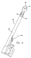
- FIG. 7 is a rear isometric view of the shaft for supporting the roll of film material in the embodiment of FIG. 1 , with the nip roller in a retracted position.
- FIG. 8 is a view similar to FIG. 7 , with the nip roller in an advanced position for engagement with the roll of film material.
- FIGS. 9 and 10 are isometric views showing the roll gripper in the embodiment of FIG. 1 in its retracted and expanded positions.
- FIG. 11 is a fragmentary isometric view of the embodiment of FIG. 1 with another embodiment of an air injector.
- the machine includes a cabinet 16 which is adapted to rest upon a table top other suitable supporting surface.
- a supply roll 17 of preconfigured film material is mounted above the cabinet in a manner described hereinafter in detail, and material is drawn from the roll and fed through the machine by a drive mechanism located behind a protective cover 18 on the front side of the cabinet.
- the film material has two layers of a suitable plastic material such as polyethylene which are sealed together to form an inflation channel 19 and rows of interconnected, inflatable cells 21 .
- the inflation channel extends longitudinally near one edge 22 of the material, and the rows of inflatable cells extend across the material in a direction generally perpendicular to the inflation channel.
- Inlet passageways 23 interconnect the inflation channel and the first cell in each of the rows, and passageways 24 interconnect adjacent cells within the rows.
- Outlet openings 26 extend between the inflation channel and the edge 22 of the material.
- the rows of cells are formed by undulating seal lines which are offset from each other such that the flow passageways in one row are adjacent to the cells in the rows on either side of it.
- This material is generally similar to the material shown in U.S. Pat. No. 6,761,960, but substantially wider. In one present embodiment, for example, the material is approximately 30 inches wide and has about 14 cells in each of the rows.
- the rows of cells are arranged in groups, and rows of perforations 27 extend laterally or transversely across the material between the groups so that the material can be torn into desired lengths.
- the cells at the ends of each group are truncated in that the seals along their outer edges are straight, with the perforations being disposed between the straight seals in adjacent groups.
- the film material is in the form of an elongated tube which has been flattened, with the longitudinally extending edges of the material being closed.
- the material can be a C-folded material having one closed edge and one open edge, or it can consist of two separate sheets which are open along both edges.
- the roll of film material is wound on a hollow cylindrical core 28 which is fabricated of a rigid or relatively rigid material such as cardboard.
- the drive mechanism 30 includes input rollers 31 – 34 and output rollers 36 – 39 which engage the edge portion of the film material and feed it through the machine.
- the input and output rollers are arranged in dual sets for engaging the film material on opposite sides of the inflation channel.
- input rollers 31 , 32 and output rollers 36 , 37 engage the film material between the inflation channel and the edge of the material
- input rollers 33 , 34 and output rollers 38 , 39 engage it between the channel and the cells.
- the feed rollers are driven by a motor (not shown) which is mounted inside the cabinet, with a drive gear on the motor shaft driving gears 41 which are affixed to the shafts on which the rollers are mounted.
- the gearing is such that the output rollers rotate slightly faster than the input rollers (e.g., an 8:7 ratio) in order to tension the film material and pull it flat as it passes through the sealing assembly to ensure that the film is sealed with no wrinkles on the surface.
- An inflator 42 is positioned between the inner and outer feed rollers and extends in an upward direction for insertion into the inflation channel of the film material.
- the inflator has a tubular base 43 , a tubular upper section 44 with longitudinally extending slotted openings 45 in the side wall thereof, and a conically tapered tip 46 with axially inclined passageways or bores 47 .
- the tip is fabricated of a material such as Teflon and is threadedly attached to the upper portion of the tube.
- a knife blade 48 is mounted on the base of the inflator for slitting the film along the inflation channel so that the material can separate from the inflator when the cells are inflated.
- Air is supplied to the inflator at a pressure on the order of 0.5 to 10 psig by an air pump (not shown) mounted inside the cabinet through an air line and fitting 49 connected to the inlet end of the inflator.
- the air is discharged into the inflation channel and the cells through slotted openings 45 and passageways 47 .
- a regulator can be connected between the pump and the inflator to allow users to adjust the air pressure and, hence, the degree of firmness to which the cells are inflated.
- a sealing assembly 51 is positioned between the input and output rollers and includes a heating element 52 and a roller 53 which presses the film material against the heating element.
- the heating element is mounted in a stationary position, and the roller is mounted on a carriage 54 .
- the roller is pressed against the heating element by a cam when the machine is operating, and withdrawn from the heating element by springs when the machine is idle.
- the roll of film material is mounted on a shaft 56 which is mounted in cantilevered fashion in a bearing assembly 57 on a support plate 58 at one end of the cabinet.
- the bearing assembly is mounted on the outer side of the plate, and a hub 59 is affixed to the shaft on the inner side of the plate for engagement with the core at the end of the roll near inflation channel 19 .
- the hub has a tricuspid body 61 which fits snugly within the end portion of the cylindrical core and a radial flange 62 for abutting engagement with the end of the core.
- a circumferentially expandable roll gripper 63 is provided at the free end of the shaft for locking engagement with the inner wall of the cylindrical core.
- the gripper has a body 64 with a plurality of axially inclined surfaces 66 which is affixed to the shaft and a head 67 with a body 68 and a plurality of circumferentially spaced jaws 69 which extend from the base in sliding engagement with the inclined surfaces.
- the head is slidably mounted on a plurality of pins 71 which extend from the body and is drawn toward and moved away from the body by a lead screw 72 which is threadedly connected to the base of the head.
- the lead screw extends coaxially within the shaft and projects from the fixed end, with an operating knob 73 affixed to the projecting portion of the screw.
- the head When the screw is turned in one direction, the head is drawn toward the body, with the inclined surfaces of the body driving the jaws in an outward direction into locking engagement with the inner wall of the core. Turning the screw in the other direction moves the head away from the body, thereby retracting the jaws and disengaging them from the core.
- a nip roller 76 is mounted on a swing arm 77 for movement into and out of engagement with the material on the supply roll to limit the flow of air from the inflator into the material on the roll and to provide a controlled rolling resistance to rotation of the roll.
- the roller is fabricated of a soft rubber material which deforms when the roller is pressed against the film material.
- the swing arm is pivotally mounted on a lay shaft 78 which extends from side plate 58 in a direction generally parallel to roll support shaft 56 , with the lay shaft being positioned below and to the rear of the roll support shaft and the nip roller aligned with the inflation channel in the material.
- the swing arm is an H-shaped device, with side arms 79 , 81 and a cross arm 82 .
- the swing arm is journaled for rotation about the lay shaft by bushings 83 , 84 in the lower or rear end portions of the side arms, and roller 76 is rotatively mounted on a shaft 85 which extends between the free end portions of the side arms.
- the nip roller is urged upwardly toward the roll of film material by a torsion spring 86 which is disposed concentrically of the lay shaft, with one end of the spring being secured to the shaft by a set screw 87 and the other bearing against cross arm 82 .
- Brake rollers 88 are mounted on a floating shaft 89 on the swing arm and are pressed into engagement with the nip roller by a screw 90 which extends between cross arm 82 and shaft 89 .
- the nip roller engages the roll at a point located approximately 60 degrees below the point at which the air is injected into the material.
- Means is provided for retracting the nip roller and latching it in a retracted position during installation and removal of the film material.
- This means includes a crank arm 91 which is connected to the swing arm by a spacer 92 , and a latch member 93 carried by the crank arm for engagement with a latch pin 94 on the outer side of plate 58 .
- the latch member is slidably mounted in a recess 96 in the crank arm for movement between latching an unlatched positions, and is urged toward the latching position by a spring (not shown) in the crank arm.
- the latch member is connected to an operating rod 97 which extends coaxially of the crank arm and projects from the free end of the arm.
- a handle 98 extends laterally from the free end of the crank arm to facilitate movement of the arm.
- the free end of the film material is threaded manually onto inflator 42 and into engagement with upper feed rollers 31 – 34 , with the inflator being received in the inflation channel 19 in the material.
- the latch mechanism is then released by depressing the free end of operating rod to disengage the latch member from the pin, following which spring 86 presses nip roller 76 against the roll.
- the air is then applied to the inflator, and while the machine is in a standby mode with the roll sitting idle on the machine, the nip roller prevents air from backfilling into the material on the roll and unwinding it from the roll.
- Nip roller 76 continues to block the inflation channel and thus prevents the air from getting going beyond the outer layer of material on the roll. It also provides a rolling resistance which prevents over-coasting when the machine is started or stopped abruptly. The resistance is provided by deformation of the relatively soft nip roller as it rotates and by the braking action provided by rollers 88 pressing against the nip roller. The amount of resistance can be controlled quite accurately by adjustment of screw 90 to vary the pressure of the brake wheels.
- the film material travels through sealing assembly 51 where roller 53 presses the material into direct contact with heating element 52 .
- the two layers of film material are thus fused together along a relatively narrow seal line 79 which extends longitudinally of the film material and across inlet passageways 23 to seal the rows of cells.
- seal line 79 which extends longitudinally of the film material and across inlet passageways 23 to seal the rows of cells.
- FIG. 11 illustrates another embodiment of an inflator for use in the embodiment of FIG. 1 .
- the inflator has a tubular base 101 similar to base 43 , with a knife blade as shown in FIG. 6 .
- This embodiment differs from the first, however in that it has a triangular or conically tapered tip 102 spaced from the base, and a plurality of circumferentially spaced, wire-like elements 103 which extend between the base and the tip in a radially convergent manner, with openings 104 between the wire-like elements and the tip, the wire-like elements and the base being adapted to be received in the inflation channel as the material passes through the machine.
- wire-like elements are spaced 60 degrees apart around the base of the inflator, but any other suitable number and/or spacing can be employed, if desired.
- Operation and use of the machine with the inflator of FIG. 11 is similar to that described above except that the air for inflating the rows of cells is discharged into the inflation channel through the openings 104 between the wire-like elements.
- the invention has a number of important features and advantages.
- the roll gripper firmly secures the roll of film material to the supply shaft, and with the gripper engaging the inner wall of the roll core, the machine can accommodate rolls of different widths, ranging from the length of the supply shaft to about twice the length of the shaft.
- the inflators with the slotted openings, axial bores and wire-like elements deliver a substantially greater flow of air than prior art inflators with a few relatively small lateral openings or a single axial opening, which makes it possible to inflate substantially longer rows of cells and wider sections of material and to do so more uniformly and faster than has heretofore been possible. They also help to maintain the air pressure in the material closer to the sealing mechanism than the inflators employed in prior art machines.
- the nip roller not only prevents the material backfilling and unwinding when the roll is sitting idle on the machine, it also facilitates the inflation of longer rows of cells and thus permits wider rolls of material to be used.
- the nip also provides rolling resistance and prevents loss of control of the roll.
Abstract
Description
Claims (24)
Priority Applications (4)
| Application Number | Priority Date | Filing Date | Title |
|---|---|---|---|
| US10/929,353 US7040073B2 (en) | 2004-08-30 | 2004-08-30 | Machine for inflating and sealing air-filled cushioning materials |
| PCT/US2005/026371 WO2006025981A2 (en) | 2004-08-30 | 2005-07-26 | Machine for inflating and sealing air-filled cushioning materials |
| EP05775082A EP1784336A4 (en) | 2004-08-30 | 2005-07-26 | Machine for inflating and sealing air-filled cushioning materials |
| US11/276,618 US7185474B2 (en) | 2004-08-30 | 2006-03-08 | Machine for inflating and sealing air filled cushioning materials |
Applications Claiming Priority (1)
| Application Number | Priority Date | Filing Date | Title |
|---|---|---|---|
| US10/929,353 US7040073B2 (en) | 2004-08-30 | 2004-08-30 | Machine for inflating and sealing air-filled cushioning materials |
Related Child Applications (1)
| Application Number | Title | Priority Date | Filing Date |
|---|---|---|---|
| US11/276,618 Continuation US7185474B2 (en) | 2004-08-30 | 2006-03-08 | Machine for inflating and sealing air filled cushioning materials |
Publications (2)
| Publication Number | Publication Date |
|---|---|
| US20060042184A1 US20060042184A1 (en) | 2006-03-02 |
| US7040073B2 true US7040073B2 (en) | 2006-05-09 |
Family
ID=35941035
Family Applications (2)
| Application Number | Title | Priority Date | Filing Date |
|---|---|---|---|
| US10/929,353 Active 2024-10-08 US7040073B2 (en) | 2004-08-30 | 2004-08-30 | Machine for inflating and sealing air-filled cushioning materials |
| US11/276,618 Active US7185474B2 (en) | 2004-08-30 | 2006-03-08 | Machine for inflating and sealing air filled cushioning materials |
Family Applications After (1)
| Application Number | Title | Priority Date | Filing Date |
|---|---|---|---|
| US11/276,618 Active US7185474B2 (en) | 2004-08-30 | 2006-03-08 | Machine for inflating and sealing air filled cushioning materials |
Country Status (3)
| Country | Link |
|---|---|
| US (2) | US7040073B2 (en) |
| EP (1) | EP1784336A4 (en) |
| WO (1) | WO2006025981A2 (en) |
Cited By (11)
| Publication number | Priority date | Publication date | Assignee | Title |
|---|---|---|---|---|
| US20060156697A1 (en) * | 2004-08-30 | 2006-07-20 | Free-Flow Packaging International, Inc. | Machine For Inflating And Sealing Air Filled Cushioning Materials |
| US20060218879A1 (en) * | 2005-03-31 | 2006-10-05 | Sealed Air Corporation (Us) | Apparatus for forming inflated packaging cushions |
| US20080141620A1 (en) * | 2006-09-15 | 2008-06-19 | Bela Szabo | Air Packing Machine Using Ultrasonic Sealing And Methods And Products Relating To Same |
| US20080222998A1 (en) * | 2006-09-26 | 2008-09-18 | Johannes Lorsch | Apparatus and method for making gas-filled filling bodies |
| US20090094939A1 (en) * | 2007-10-12 | 2009-04-16 | Pregis Innovative Packaging, Inc. | Inflation and sealing device with disengagement mechanism |
| US20110172072A1 (en) * | 2010-01-06 | 2011-07-14 | Pregis Innovative Packaging, Inc. | Packaging pillow device with upstream components |
| US20110192490A1 (en) * | 2006-08-01 | 2011-08-11 | Pregis Innovative Packaging, Inc. | Inflation nozzle with valve-locating probe and pulsating air supply |
| US9010075B2 (en) | 2011-03-31 | 2015-04-21 | Dell Products Lp | Systems and methods for gas packaging |
| USD770282S1 (en) * | 2015-07-29 | 2016-11-01 | Ameson Packing (Xiamen) Co., Ltd. | Inflatable packing material |
| US11402066B2 (en) * | 2015-05-22 | 2022-08-02 | Jiaying Zhang | Inflation method for air cushion body, inflation system of same, and inflation apparatus thereof |
| US11542086B2 (en) | 2018-08-06 | 2023-01-03 | Better Packages, Inc. | Packaging apparatus for film inflation and method thereof |
Families Citing this family (27)
| Publication number | Priority date | Publication date | Assignee | Title |
|---|---|---|---|---|
| KR100828468B1 (en) * | 2002-11-04 | 2008-05-13 | 더 프록터 앤드 갬블 캄파니 | Striped liquid personal cleansing compositions containing a cleansing phase and a separate benefit phase with improved stability |
| EP1617809B1 (en) * | 2003-05-01 | 2015-07-08 | The Procter & Gamble Company | Striped liquid personal cleansing compositions containing a cleansing phase and a separate benefit phase comprising a high internal phase emulsion |
| US20070181258A1 (en) * | 2004-11-05 | 2007-08-09 | Free-Flow Packaging International, Inc. | System for producing rolls of air-filled cushioning material |
| CA2603299A1 (en) * | 2005-04-13 | 2006-10-26 | The Procter & Gamble Company | Structured multi-phased personal care composition comprising branched anionic surfactants |
| ES2424034T3 (en) | 2006-09-20 | 2013-09-26 | Pregis Innovative Packaging Inc. | Inflation and sealing device for inflatable air pads |
| US7503156B2 (en) * | 2007-01-11 | 2009-03-17 | Ralph Eibert | Method and apparatus for making dunnage |
| US8105996B2 (en) * | 2007-03-30 | 2012-01-31 | The Procter & Gamble Company | Multiphase personal care composition comprising a structuring |
| US8158566B2 (en) * | 2007-03-30 | 2012-04-17 | The Procter & Gamble Company | Multiphase personal care composition comprising a structuring system that comprises an associative polymer, a low HLB emulsifier and an electrolyte |
| US20080270157A1 (en) * | 2007-04-26 | 2008-10-30 | Applied Prototype, Inc. | Method and apparatus for selling disposable inflatable air mattresses as temporary bedding material |
| NL2003907C2 (en) | 2009-12-04 | 2011-06-07 | Ideepak Holding B V | Blow unit for an apparatus for making air-filled bags, apparatus comprising such a blow unit, system comprising such an apparatus and a method for making air-filled bags. |
| TWI535629B (en) * | 2012-08-15 | 2016-06-01 | 亞比斯包材工場股份有限公司 | Continuous sealing device and its storage and delivery table |
| US9994343B2 (en) | 2013-03-15 | 2018-06-12 | Pregis Innovative Packaging Llc | Replaceable blade |
| US20140261871A1 (en) * | 2013-03-15 | 2014-09-18 | Pregis Innovative Packaging Inc. | Nozzle With Side and Tip Outlet |
| US10328653B2 (en) | 2014-02-24 | 2019-06-25 | Pregis Innovative Packaging Llc | Inflation and sealing device with inclined components |
| WO2016077327A1 (en) | 2014-11-10 | 2016-05-19 | The Procter & Gamble Company | Personal care compositions with two benefit phases |
| MX2017006148A (en) | 2014-11-10 | 2017-07-27 | Procter & Gamble | Personal care compositions with two benefit phases. |
| US10966916B2 (en) | 2014-11-10 | 2021-04-06 | The Procter And Gamble Company | Personal care compositions |
| US10906678B2 (en) * | 2015-11-19 | 2021-02-02 | Air-Bag Packing Co., Ltd. | Inflating stick and processing machine |
| TWI579203B (en) * | 2015-11-19 | 2017-04-21 | Air-Bag Packing Co Ltd | Inflatable rod and its processing machine |
| JP7025346B2 (en) * | 2016-03-28 | 2022-02-24 | プレジス・イノベーティブ・パッケージング・エルエルシー | Idler roller |
| US20180099831A1 (en) * | 2016-10-12 | 2018-04-12 | Ampacs Corporation | Inflatable cushion packaging mechine |
| WO2019079405A1 (en) | 2017-10-20 | 2019-04-25 | The Procter & Gamble Company | Aerosol foam skin cleanser |
| WO2019079409A1 (en) | 2017-10-20 | 2019-04-25 | The Procter & Gamble Company | Aerosol foam skin cleanser |
| US11117697B2 (en) * | 2018-02-14 | 2021-09-14 | Pregis Innovative Packaging Llc | Compression belt for inflation and sealing devices |
| US11207847B2 (en) * | 2018-10-04 | 2021-12-28 | Automated Packaging Systems, Llc | Air cushion inflation machine |
| CN113015904A (en) | 2018-11-29 | 2021-06-22 | 宝洁公司 | Method for screening personal care products |
| JP2021030509A (en) * | 2019-08-20 | 2021-03-01 | 株式会社クルーズ | Air cushioning material manufacturing apparatus |
Citations (85)
| Publication number | Priority date | Publication date | Assignee | Title |
|---|---|---|---|---|
| US2904100A (en) | 1956-05-08 | 1959-09-15 | Nicholas Langer | Sealing member for heat sealing machines |
| US3253122A (en) | 1964-04-10 | 1966-05-24 | Weldotron Corp | Impulse heat sealing means |
| US3359703A (en) | 1962-07-19 | 1967-12-26 | Stamicarbon | Apparatus for making and filling a series of bags |
| US3389534A (en) | 1965-09-16 | 1968-06-25 | John M. Pendleton | Machine for making cushioning packaging material or the like |
| US3492783A (en) | 1964-10-30 | 1970-02-03 | Arnold Dohmeier | Apparatus for forming and filling bags |
| US3554135A (en) | 1968-10-01 | 1971-01-12 | Goodyear Tire & Rubber | Shoring device |
| US3575757A (en) * | 1967-12-08 | 1971-04-20 | Reinforced Air Corp | Process for making inflated articles |
| US3660189A (en) | 1969-04-28 | 1972-05-02 | Constantine T Troy | Closed cell structure and methods and apparatus for its manufacture |
| US3667593A (en) | 1970-03-30 | 1972-06-06 | John M Pendleton | Flowable dunnage apparatus and method of packaging with flowable and compliable inflated dunnage material |
| US3674614A (en) | 1970-03-02 | 1972-07-04 | Rospatch Corp | Unitary label assembly of interlinked labels |
| US3703430A (en) | 1971-03-12 | 1972-11-21 | Joseph L Rich | Apparatus for fabricating plastic cushioning and insulating material |
| US3769145A (en) | 1971-05-03 | 1973-10-30 | Kimberly Clark Co | Reinforced plastic cushioning material |
| US3817803A (en) | 1972-06-19 | 1974-06-18 | Fmc Corp | Method of making a cellular cushioning structure |
| US3868285A (en) | 1973-07-18 | 1975-02-25 | Constantine T Troy | Methods and apparatus for the manufacture of cellular cushioning materials |
| US3889743A (en) | 1971-03-16 | 1975-06-17 | Michael C Presnick | Inflatable insulation for packaging |
| US3938298A (en) | 1974-05-20 | 1976-02-17 | Minnesota Mining And Manufacturing Company | System for inflation and sealing of air cushions |
| US4017351A (en) | 1975-12-24 | 1977-04-12 | Minnesota Mining And Manufacturing Company | System and device for inflating and sealing air inflated cushioning material |
| US4021283A (en) | 1974-01-24 | 1977-05-03 | Weikert Roy J | Method of making aseptic packaging |
| US4096306A (en) | 1975-12-24 | 1978-06-20 | Minnesota Mining And Manufacturing Company | Strip material used in forming air inflated cushioning material |
| FR2389547A1 (en) | 1977-05-06 | 1978-12-01 | Raskin Claude | Secure packing of articles - uses inflated flexible bulbs to fill space between article and box |
| US4169002A (en) | 1975-12-24 | 1979-09-25 | Minnesota Mining And Manufacturing Company | Method for forming air inflated cushioning material |
| US4415398A (en) | 1979-09-14 | 1983-11-15 | Ranpak Corp. | Cushioning dunnage apparatus |
| US4465188A (en) | 1982-07-02 | 1984-08-14 | Barbecon Inc. | Inflatable packaging structure |
| US4551379A (en) | 1983-08-31 | 1985-11-05 | Kerr Stanley R | Inflatable packaging material |
| US4564407A (en) | 1983-11-11 | 1986-01-14 | Orihiro Co., Ltd. | Manufacturing method and manufacturing equipment for plastic air cell cushioning material |
| US4586319A (en) | 1982-09-30 | 1986-05-06 | Minigrip, Inc. | Method of and means for easy opening bags |
| US4596111A (en) | 1983-06-27 | 1986-06-24 | Ambrose Charles J | Apparatus and method for packaging delicate articles |
| FR2580597A1 (en) | 1985-04-19 | 1986-10-24 | Yamashiro Hiroshi | Shock absorbing device for package and method and apparatus for manufacturing such a device |
| US4680073A (en) | 1986-03-17 | 1987-07-14 | Reynolds Metals Company | Method and apparatus for heat sealing |
| US4793123A (en) | 1987-11-16 | 1988-12-27 | Pharo Daniel A | Rolled-up packaging system and method |
| US4847126A (en) | 1982-07-01 | 1989-07-11 | Hiroshi Yamashiro | Elongated plastic material |
| US4850912A (en) | 1987-10-30 | 1989-07-25 | Toshimichi Koyanagi | Container for sealingly containing a fluid |
| US4872558A (en) | 1987-08-25 | 1989-10-10 | Pharo Daniel A | Bag-in-bag packaging system |
| US4874093A (en) | 1987-08-25 | 1989-10-17 | Pharo Daniel A | Clam-like packaging system |
| GB2218401A (en) | 1988-05-11 | 1989-11-15 | S P Chemical Kabushiki Kaisha | Improvements in or relating to packages |
| US4918904A (en) | 1987-08-25 | 1990-04-24 | Pharo Daniel A | Method for forming clam-like packaging system |
| US4941754A (en) | 1989-05-26 | 1990-07-17 | Paul Murdock | Inflatable self-supporting bag |
| US4949530A (en) | 1987-08-25 | 1990-08-21 | Pharo Daniel A | Method for forming bag-in-bag packaging system |
| US4981006A (en) | 1988-07-20 | 1991-01-01 | Sasib S.P.A. | Device for sealing the overlapped end flaps of a thermoplastic material wrapper for packages, particularly for packages of cigarettes |
| US5009318A (en) | 1986-04-09 | 1991-04-23 | Lepinoy Industrie | Method, device and padded product for maintaining an object |
| US5046258A (en) | 1988-02-10 | 1991-09-10 | Molins Plc | Wrapping machines |
| US5203761A (en) | 1991-06-17 | 1993-04-20 | Sealed Air Corporation | Apparatus for fabricating dunnage material from continuous web material |
| US5216868A (en) | 1992-01-28 | 1993-06-08 | Andrew K. Cooper | Packaging product and machine for making same |
| WO1994007678A1 (en) | 1992-10-02 | 1994-04-14 | Klerk's Plastic Industrie B.V. | Device for producing a cushion filled with a gaseous medium |
| US5340632A (en) | 1991-05-03 | 1994-08-23 | Michel Chappuis | Padding element for the packing of objects and device for the manufacturing of the same |
| JPH0716961A (en) | 1993-07-03 | 1995-01-20 | Shin Nippon:Kk | Manufacturing device for packing air cushion |
| US5402892A (en) | 1992-08-31 | 1995-04-04 | Burlington Consolidated Limited Incorporation | Impact resistant wrapping system |
| US5406770A (en) | 1993-05-24 | 1995-04-18 | Fikacek; Karel J. | Packaging apparatus for random size articles |
| JPH07165267A (en) | 1993-12-10 | 1995-06-27 | Shin Nippon:Kk | Device for production of air cushion |
| US5427830A (en) | 1992-10-14 | 1995-06-27 | Air Packaging Technologies, Inc. | Continuous, inflatable plastic wrapping material |
| US5447235A (en) | 1994-07-18 | 1995-09-05 | Air Packaging Technologies, Inc. | Bag with squeeze valve and method for packaging an article therein |
| US5454642A (en) | 1993-07-16 | 1995-10-03 | Novus Packaging Corporation | Inflatable flat bag packaging cushion and methods of operating and making the same |
| US5535888A (en) | 1994-11-23 | 1996-07-16 | Novus Packaging Corporation | Thermal insulating and cushioning package and method of making the same |
| US5552003A (en) | 1994-10-04 | 1996-09-03 | Hoover; Gregory A. | Method for producing inflated dunnage |
| US5581983A (en) | 1993-11-05 | 1996-12-10 | Shinwa Corporation | Gas injection device for gas bag having serial closed cells |
| US5604016A (en) | 1994-03-29 | 1997-02-18 | Decomatic S.A., Societe Anonyme | Information-medium sleeve and process for manufacturing it |
| US5651237A (en) | 1995-06-06 | 1997-07-29 | Novus Packaging Corporation | Apparatus and methodology for packaging items incorporating an inflatable packaging system |
| US5658632A (en) | 1995-05-23 | 1997-08-19 | Geocel Corporation | Masking device |
| US5660662A (en) | 1995-04-25 | 1997-08-26 | Testone Enterprises, Inc. | Method and apparatus for forming filled cushions, and filled cushions |
| US5692833A (en) | 1994-10-26 | 1997-12-02 | Novus Packaging | Inflatable packaging cone and method of making the same |
| US5693163A (en) | 1994-10-04 | 1997-12-02 | Hoover; Gregory A. | Inflated dunnage and method for its production |
| DE29717551U1 (en) | 1997-10-01 | 1998-03-12 | Pelyplastic Gmbh & Co | Pouches, assortment of pouches and range of pouches |
| EP0836926A2 (en) | 1996-10-18 | 1998-04-22 | C.P.S. B.V. | Apparatus for manufacturing a cushion filled with a gaseous medium |
| US5755328A (en) | 1994-07-21 | 1998-05-26 | Deluca; Nicholas Paolo | Flutter valve assembly for inflatable packaging and the like |
| US5755082A (en) | 1996-02-01 | 1998-05-26 | Hitachi Electronics Services Co., Ltd. | Manufacturing equipment for cushioning material |
| WO1998040276A1 (en) | 1997-03-13 | 1998-09-17 | Sealed Air Corporation | Inflatable cushion forming machine |
| US5824392A (en) | 1994-03-24 | 1998-10-20 | Idemitsu Petrochemical Co., Ltd. | Method of producing an air cushion and an apparatus for the same |
| US5858153A (en) | 1997-01-17 | 1999-01-12 | Colgate-Palmolive Company | Method for making tubular containers |
| US5937614A (en) | 1994-02-01 | 1999-08-17 | Watkins; David Leonard | Bag sealing apparatus |
| US6015047A (en) | 1998-04-08 | 2000-01-18 | Greenland; Steven J. | Inflatable package cushioning and method of using same |
| WO2000043198A1 (en) | 1999-01-20 | 2000-07-27 | Case Packing Sales Europe B.V. | Plastic film and method for making pneumatically filled packing cushions |
| WO2000043270A1 (en) | 1999-01-20 | 2000-07-27 | Case Packing Sales Europe B.V. | Machine for manufacturing pneumatically filled packing cushions |
| WO2000053501A1 (en) | 1999-03-09 | 2000-09-14 | Free-Flow Packaging International, Inc. | Machine and method for manufacturing a continuous production of pneumatically filled inflatable packaging pillows |
| DE19913408A1 (en) | 1999-03-25 | 2000-10-05 | Johannes Loersch | Plastic tube for producing gas-filled packing material consists of two sheets sealed together along their edges with transverse spot-welds forming inflatable pockets and line of perforations each pair of spot-welded lines |
| WO2000064672A1 (en) | 1999-04-22 | 2000-11-02 | Ebrahim Simhaee | Inflatable air cell dunnage |
| US6272815B1 (en) | 1998-11-03 | 2001-08-14 | Klockner-Bartelt, Inc. | Servo-controlled pouch making apparatus |
| WO2001085434A2 (en) | 2000-05-08 | 2001-11-15 | Case Packing Sales Europe B.V. | Device for manufacturing cushions filled with a medium, series of cushions and cushion manufactured by such a device and tubular foil |
| US6375785B1 (en) | 1999-04-15 | 2002-04-23 | Case Packaging Sales Europe Bv | Device for manufacturing cushions filled with a gaseous medium |
| US6410119B1 (en) | 2000-11-21 | 2002-06-25 | Free-Flow Packaging International, Inc. | Inflatable, cushioning, bubble wrap product having multiple, interconnected, bubble structures |
| US6460313B1 (en) | 1999-05-24 | 2002-10-08 | Andrew Cooper | Packaging filler product and machine for producing same |
| US6565946B2 (en) * | 2000-08-14 | 2003-05-20 | Free-Flowing Packaging International, Inc. | Web of film formed with a pattern of pillows to be inflated and sealed and used in packaging |
| US6582800B2 (en) | 2000-01-20 | 2003-06-24 | Free-Flow Packaging International, Inc. | Method for making pneumatically filled packing cushions |
| US6598373B2 (en) * | 2001-02-13 | 2003-07-29 | Sealed Air Corporation (Us) | Apparatus and method for forming inflated containers |
| US20030163976A1 (en) | 2002-03-01 | 2003-09-04 | Andrew Perkins | Machine and method for inflating and sealing air-filled packing cushions |
| US6651406B2 (en) * | 2001-02-13 | 2003-11-25 | Sealed Air Corporation (Us) | Apparatus and method for forming inflated containers |
Family Cites Families (8)
| Publication number | Priority date | Publication date | Assignee | Title |
|---|---|---|---|---|
| US3214107A (en) * | 1964-07-21 | 1965-10-26 | Phelps Dodge Copper Prod | Adjustable locking mandrel for spools |
| CH562273A5 (en) * | 1972-03-07 | 1975-05-30 | Ciba Geigy Ag | |
| DE2815310C2 (en) * | 1978-04-08 | 1982-06-16 | Jagenberg-Werke AG, 4000 Düsseldorf | Clamping head for winding cores |
| JPH075123B2 (en) * | 1991-06-25 | 1995-01-25 | 株式会社柏原製袋 | A method for continuously filling fluid into a plurality of fluid-tightly sealed bags for fluid |
| DE10013290A1 (en) * | 2000-03-17 | 2001-09-20 | Ratiopac Systemverpackung Gmbh | Holder for roll of stretch film for wrapping articles on pallet comprises core which fits into central hole of the roll and has conical recesses at each end with flexible walls which are pressed against inner surface of central hole |
| GB2384459A (en) * | 2002-01-25 | 2003-07-30 | John Stuart Greenwood | Manufacture of air cushions from tubing with a gas injector continuously within the tubing |
| NL1020273C2 (en) * | 2002-03-28 | 2003-09-30 | Ideepak Holding B V | Seal device. |
| US7040073B2 (en) * | 2004-08-30 | 2006-05-09 | Free-Flow Packaging International | Machine for inflating and sealing air-filled cushioning materials |
-
2004
- 2004-08-30 US US10/929,353 patent/US7040073B2/en active Active
-
2005
- 2005-07-26 EP EP05775082A patent/EP1784336A4/en not_active Withdrawn
- 2005-07-26 WO PCT/US2005/026371 patent/WO2006025981A2/en active Application Filing
-
2006
- 2006-03-08 US US11/276,618 patent/US7185474B2/en active Active
Patent Citations (96)
| Publication number | Priority date | Publication date | Assignee | Title |
|---|---|---|---|---|
| US2904100A (en) | 1956-05-08 | 1959-09-15 | Nicholas Langer | Sealing member for heat sealing machines |
| US3359703A (en) | 1962-07-19 | 1967-12-26 | Stamicarbon | Apparatus for making and filling a series of bags |
| US3253122A (en) | 1964-04-10 | 1966-05-24 | Weldotron Corp | Impulse heat sealing means |
| US3492783A (en) | 1964-10-30 | 1970-02-03 | Arnold Dohmeier | Apparatus for forming and filling bags |
| US3389534A (en) | 1965-09-16 | 1968-06-25 | John M. Pendleton | Machine for making cushioning packaging material or the like |
| US3575757A (en) * | 1967-12-08 | 1971-04-20 | Reinforced Air Corp | Process for making inflated articles |
| US3554135A (en) | 1968-10-01 | 1971-01-12 | Goodyear Tire & Rubber | Shoring device |
| US3660189A (en) | 1969-04-28 | 1972-05-02 | Constantine T Troy | Closed cell structure and methods and apparatus for its manufacture |
| US3674614A (en) | 1970-03-02 | 1972-07-04 | Rospatch Corp | Unitary label assembly of interlinked labels |
| US3667593A (en) | 1970-03-30 | 1972-06-06 | John M Pendleton | Flowable dunnage apparatus and method of packaging with flowable and compliable inflated dunnage material |
| US3703430A (en) | 1971-03-12 | 1972-11-21 | Joseph L Rich | Apparatus for fabricating plastic cushioning and insulating material |
| US3889743A (en) | 1971-03-16 | 1975-06-17 | Michael C Presnick | Inflatable insulation for packaging |
| US3769145A (en) | 1971-05-03 | 1973-10-30 | Kimberly Clark Co | Reinforced plastic cushioning material |
| US3817803A (en) | 1972-06-19 | 1974-06-18 | Fmc Corp | Method of making a cellular cushioning structure |
| US3868285A (en) | 1973-07-18 | 1975-02-25 | Constantine T Troy | Methods and apparatus for the manufacture of cellular cushioning materials |
| US4021283A (en) | 1974-01-24 | 1977-05-03 | Weikert Roy J | Method of making aseptic packaging |
| US3938298A (en) | 1974-05-20 | 1976-02-17 | Minnesota Mining And Manufacturing Company | System for inflation and sealing of air cushions |
| US4017351A (en) | 1975-12-24 | 1977-04-12 | Minnesota Mining And Manufacturing Company | System and device for inflating and sealing air inflated cushioning material |
| US4096306A (en) | 1975-12-24 | 1978-06-20 | Minnesota Mining And Manufacturing Company | Strip material used in forming air inflated cushioning material |
| US4169002A (en) | 1975-12-24 | 1979-09-25 | Minnesota Mining And Manufacturing Company | Method for forming air inflated cushioning material |
| FR2389547A1 (en) | 1977-05-06 | 1978-12-01 | Raskin Claude | Secure packing of articles - uses inflated flexible bulbs to fill space between article and box |
| US4415398A (en) | 1979-09-14 | 1983-11-15 | Ranpak Corp. | Cushioning dunnage apparatus |
| US4847126A (en) | 1982-07-01 | 1989-07-11 | Hiroshi Yamashiro | Elongated plastic material |
| US4465188A (en) | 1982-07-02 | 1984-08-14 | Barbecon Inc. | Inflatable packaging structure |
| US4586319A (en) | 1982-09-30 | 1986-05-06 | Minigrip, Inc. | Method of and means for easy opening bags |
| US4596111A (en) | 1983-06-27 | 1986-06-24 | Ambrose Charles J | Apparatus and method for packaging delicate articles |
| US4551379A (en) | 1983-08-31 | 1985-11-05 | Kerr Stanley R | Inflatable packaging material |
| US4564407A (en) | 1983-11-11 | 1986-01-14 | Orihiro Co., Ltd. | Manufacturing method and manufacturing equipment for plastic air cell cushioning material |
| FR2580597A1 (en) | 1985-04-19 | 1986-10-24 | Yamashiro Hiroshi | Shock absorbing device for package and method and apparatus for manufacturing such a device |
| US4680073A (en) | 1986-03-17 | 1987-07-14 | Reynolds Metals Company | Method and apparatus for heat sealing |
| US5009318A (en) | 1986-04-09 | 1991-04-23 | Lepinoy Industrie | Method, device and padded product for maintaining an object |
| US4949530A (en) | 1987-08-25 | 1990-08-21 | Pharo Daniel A | Method for forming bag-in-bag packaging system |
| US4872558A (en) | 1987-08-25 | 1989-10-10 | Pharo Daniel A | Bag-in-bag packaging system |
| US4874093A (en) | 1987-08-25 | 1989-10-17 | Pharo Daniel A | Clam-like packaging system |
| US4918904A (en) | 1987-08-25 | 1990-04-24 | Pharo Daniel A | Method for forming clam-like packaging system |
| US4850912A (en) | 1987-10-30 | 1989-07-25 | Toshimichi Koyanagi | Container for sealingly containing a fluid |
| US4793123A (en) | 1987-11-16 | 1988-12-27 | Pharo Daniel A | Rolled-up packaging system and method |
| US5046258A (en) | 1988-02-10 | 1991-09-10 | Molins Plc | Wrapping machines |
| GB2218401A (en) | 1988-05-11 | 1989-11-15 | S P Chemical Kabushiki Kaisha | Improvements in or relating to packages |
| US4981006A (en) | 1988-07-20 | 1991-01-01 | Sasib S.P.A. | Device for sealing the overlapped end flaps of a thermoplastic material wrapper for packages, particularly for packages of cigarettes |
| US4941754A (en) | 1989-05-26 | 1990-07-17 | Paul Murdock | Inflatable self-supporting bag |
| US5340632A (en) | 1991-05-03 | 1994-08-23 | Michel Chappuis | Padding element for the packing of objects and device for the manufacturing of the same |
| US5203761A (en) | 1991-06-17 | 1993-04-20 | Sealed Air Corporation | Apparatus for fabricating dunnage material from continuous web material |
| US5216868A (en) | 1992-01-28 | 1993-06-08 | Andrew K. Cooper | Packaging product and machine for making same |
| US5402892A (en) | 1992-08-31 | 1995-04-04 | Burlington Consolidated Limited Incorporation | Impact resistant wrapping system |
| WO1994007678A1 (en) | 1992-10-02 | 1994-04-14 | Klerk's Plastic Industrie B.V. | Device for producing a cushion filled with a gaseous medium |
| US5427830A (en) | 1992-10-14 | 1995-06-27 | Air Packaging Technologies, Inc. | Continuous, inflatable plastic wrapping material |
| US5406770A (en) | 1993-05-24 | 1995-04-18 | Fikacek; Karel J. | Packaging apparatus for random size articles |
| JPH0716961A (en) | 1993-07-03 | 1995-01-20 | Shin Nippon:Kk | Manufacturing device for packing air cushion |
| US5454642A (en) | 1993-07-16 | 1995-10-03 | Novus Packaging Corporation | Inflatable flat bag packaging cushion and methods of operating and making the same |
| US5581983A (en) | 1993-11-05 | 1996-12-10 | Shinwa Corporation | Gas injection device for gas bag having serial closed cells |
| JPH07165267A (en) | 1993-12-10 | 1995-06-27 | Shin Nippon:Kk | Device for production of air cushion |
| US5937614A (en) | 1994-02-01 | 1999-08-17 | Watkins; David Leonard | Bag sealing apparatus |
| US5824392A (en) | 1994-03-24 | 1998-10-20 | Idemitsu Petrochemical Co., Ltd. | Method of producing an air cushion and an apparatus for the same |
| US5604016A (en) | 1994-03-29 | 1997-02-18 | Decomatic S.A., Societe Anonyme | Information-medium sleeve and process for manufacturing it |
| US5447235A (en) | 1994-07-18 | 1995-09-05 | Air Packaging Technologies, Inc. | Bag with squeeze valve and method for packaging an article therein |
| US5755328A (en) | 1994-07-21 | 1998-05-26 | Deluca; Nicholas Paolo | Flutter valve assembly for inflatable packaging and the like |
| USRE36501E (en) | 1994-10-04 | 2000-01-18 | Hoover; Gregory A. | Method for producing inflated dunnage |
| US5552003A (en) | 1994-10-04 | 1996-09-03 | Hoover; Gregory A. | Method for producing inflated dunnage |
| US5693163A (en) | 1994-10-04 | 1997-12-02 | Hoover; Gregory A. | Inflated dunnage and method for its production |
| US5692833A (en) | 1994-10-26 | 1997-12-02 | Novus Packaging | Inflatable packaging cone and method of making the same |
| US5535888A (en) | 1994-11-23 | 1996-07-16 | Novus Packaging Corporation | Thermal insulating and cushioning package and method of making the same |
| US5660662A (en) | 1995-04-25 | 1997-08-26 | Testone Enterprises, Inc. | Method and apparatus for forming filled cushions, and filled cushions |
| US5658632A (en) | 1995-05-23 | 1997-08-19 | Geocel Corporation | Masking device |
| US5651237A (en) | 1995-06-06 | 1997-07-29 | Novus Packaging Corporation | Apparatus and methodology for packaging items incorporating an inflatable packaging system |
| US5755082A (en) | 1996-02-01 | 1998-05-26 | Hitachi Electronics Services Co., Ltd. | Manufacturing equipment for cushioning material |
| EP0836926A2 (en) | 1996-10-18 | 1998-04-22 | C.P.S. B.V. | Apparatus for manufacturing a cushion filled with a gaseous medium |
| US5873215A (en) | 1996-10-18 | 1999-02-23 | Free-Flow Packaging International, Inc. | Machine and method for manufacturing pneumatically filled packing cushions |
| US5858153A (en) | 1997-01-17 | 1999-01-12 | Colgate-Palmolive Company | Method for making tubular containers |
| WO1998040276A1 (en) | 1997-03-13 | 1998-09-17 | Sealed Air Corporation | Inflatable cushion forming machine |
| US5942076A (en) | 1997-03-13 | 1999-08-24 | Sealed Air Corporation | Inflatable cushion forming machine |
| DE29717551U1 (en) | 1997-10-01 | 1998-03-12 | Pelyplastic Gmbh & Co | Pouches, assortment of pouches and range of pouches |
| US6015047A (en) | 1998-04-08 | 2000-01-18 | Greenland; Steven J. | Inflatable package cushioning and method of using same |
| US6272815B1 (en) | 1998-11-03 | 2001-08-14 | Klockner-Bartelt, Inc. | Servo-controlled pouch making apparatus |
| WO2000043270A1 (en) | 1999-01-20 | 2000-07-27 | Case Packing Sales Europe B.V. | Machine for manufacturing pneumatically filled packing cushions |
| WO2000043198A1 (en) | 1999-01-20 | 2000-07-27 | Case Packing Sales Europe B.V. | Plastic film and method for making pneumatically filled packing cushions |
| US20030118778A1 (en) | 1999-03-09 | 2003-06-26 | Free-Flow Packaging International, Inc. | Film material for air-filled packing cushions |
| US6209286B1 (en) * | 1999-03-09 | 2001-04-03 | Novus Packaging Corporation | Machine and method for manufacturing a continuous production of pneumatically filled inflatable packaging pillows |
| WO2000053501A1 (en) | 1999-03-09 | 2000-09-14 | Free-Flow Packaging International, Inc. | Machine and method for manufacturing a continuous production of pneumatically filled inflatable packaging pillows |
| DE19913408C2 (en) | 1999-03-25 | 2003-04-10 | Johannes Loersch | Plastic hose for the production of gas-filled packing elements and method for their production and device for carrying out the method |
| DE19913408A1 (en) | 1999-03-25 | 2000-10-05 | Johannes Loersch | Plastic tube for producing gas-filled packing material consists of two sheets sealed together along their edges with transverse spot-welds forming inflatable pockets and line of perforations each pair of spot-welded lines |
| US6375785B1 (en) | 1999-04-15 | 2002-04-23 | Case Packaging Sales Europe Bv | Device for manufacturing cushions filled with a gaseous medium |
| US6423166B1 (en) | 1999-04-22 | 2002-07-23 | Ebrahim Simhaee | Method of making collapsed air cell dunnage suitable for inflation |
| WO2000064672A1 (en) | 1999-04-22 | 2000-11-02 | Ebrahim Simhaee | Inflatable air cell dunnage |
| US6460313B1 (en) | 1999-05-24 | 2002-10-08 | Andrew Cooper | Packaging filler product and machine for producing same |
| US6786022B2 (en) | 2000-01-20 | 2004-09-07 | Free-Flow Packaging International, Inc. | System, method and material for making pneumatically filled packing cushions |
| US20040206050A1 (en) | 2000-01-20 | 2004-10-21 | Free-Flow Packaging International, Inc. | System, method and material for making pneumatically filled packing cushions |
| US6582800B2 (en) | 2000-01-20 | 2003-06-24 | Free-Flow Packaging International, Inc. | Method for making pneumatically filled packing cushions |
| WO2001085434A2 (en) | 2000-05-08 | 2001-11-15 | Case Packing Sales Europe B.V. | Device for manufacturing cushions filled with a medium, series of cushions and cushion manufactured by such a device and tubular foil |
| US6659150B1 (en) | 2000-08-14 | 2003-12-09 | Free-Flow Packaging International, Inc. | Apparatus for inflating and sealing air-filled packing cushions |
| US6565946B2 (en) * | 2000-08-14 | 2003-05-20 | Free-Flowing Packaging International, Inc. | Web of film formed with a pattern of pillows to be inflated and sealed and used in packaging |
| US6761960B2 (en) | 2000-11-21 | 2004-07-13 | Free-Flow Packaging International, Inc. | Inflatable, cushioning, bubble wrap product having multiple, interconnected, bubble structures |
| US6410119B1 (en) | 2000-11-21 | 2002-06-25 | Free-Flow Packaging International, Inc. | Inflatable, cushioning, bubble wrap product having multiple, interconnected, bubble structures |
| US6598373B2 (en) * | 2001-02-13 | 2003-07-29 | Sealed Air Corporation (Us) | Apparatus and method for forming inflated containers |
| US6651406B2 (en) * | 2001-02-13 | 2003-11-25 | Sealed Air Corporation (Us) | Apparatus and method for forming inflated containers |
| US20030163976A1 (en) | 2002-03-01 | 2003-09-04 | Andrew Perkins | Machine and method for inflating and sealing air-filled packing cushions |
Non-Patent Citations (3)
| Title |
|---|
| Air-Fil 1200 photographs (no date but prior to application's filing date). |
| Claims from 10/031,111 (PCT/NL01/00351). |
| Fuss and Yampolsky declaration, 09/488,622. |
Cited By (16)
| Publication number | Priority date | Publication date | Assignee | Title |
|---|---|---|---|---|
| US7185474B2 (en) * | 2004-08-30 | 2007-03-06 | Free Flow Packaging International, Inc. | Machine for inflating and sealing air filled cushioning materials |
| US20060156697A1 (en) * | 2004-08-30 | 2006-07-20 | Free-Flow Packaging International, Inc. | Machine For Inflating And Sealing Air Filled Cushioning Materials |
| US20060218879A1 (en) * | 2005-03-31 | 2006-10-05 | Sealed Air Corporation (Us) | Apparatus for forming inflated packaging cushions |
| US20110192490A1 (en) * | 2006-08-01 | 2011-08-11 | Pregis Innovative Packaging, Inc. | Inflation nozzle with valve-locating probe and pulsating air supply |
| US8424552B2 (en) * | 2006-08-01 | 2013-04-23 | Pregis Innovative Packaging, Inc. | Inflation nozzle with valve-locating probe and pulsating air supply |
| US20080141620A1 (en) * | 2006-09-15 | 2008-06-19 | Bela Szabo | Air Packing Machine Using Ultrasonic Sealing And Methods And Products Relating To Same |
| US20080222998A1 (en) * | 2006-09-26 | 2008-09-18 | Johannes Lorsch | Apparatus and method for making gas-filled filling bodies |
| US7698874B2 (en) * | 2006-09-26 | 2010-04-20 | Loersch Johannes | Apparatus and method for making gas-filled filling bodies |
| US8061110B2 (en) | 2007-10-12 | 2011-11-22 | Pregis Innovative Packaging, Inc. | Inflation and sealing device with disengagement mechanism |
| US20090094939A1 (en) * | 2007-10-12 | 2009-04-16 | Pregis Innovative Packaging, Inc. | Inflation and sealing device with disengagement mechanism |
| US20110172072A1 (en) * | 2010-01-06 | 2011-07-14 | Pregis Innovative Packaging, Inc. | Packaging pillow device with upstream components |
| US9168715B2 (en) | 2010-01-06 | 2015-10-27 | Pregis Innovative Packaging Llc | Packaging pillow device with upstream components |
| US9010075B2 (en) | 2011-03-31 | 2015-04-21 | Dell Products Lp | Systems and methods for gas packaging |
| US11402066B2 (en) * | 2015-05-22 | 2022-08-02 | Jiaying Zhang | Inflation method for air cushion body, inflation system of same, and inflation apparatus thereof |
| USD770282S1 (en) * | 2015-07-29 | 2016-11-01 | Ameson Packing (Xiamen) Co., Ltd. | Inflatable packing material |
| US11542086B2 (en) | 2018-08-06 | 2023-01-03 | Better Packages, Inc. | Packaging apparatus for film inflation and method thereof |
Also Published As
| Publication number | Publication date |
|---|---|
| US20060156697A1 (en) | 2006-07-20 |
| US20060042184A1 (en) | 2006-03-02 |
| EP1784336A4 (en) | 2012-11-21 |
| WO2006025981A3 (en) | 2006-04-20 |
| EP1784336A2 (en) | 2007-05-16 |
| US7185474B2 (en) | 2007-03-06 |
| WO2006025981A2 (en) | 2006-03-09 |
Similar Documents
| Publication | Publication Date | Title |
|---|---|---|
| US7040073B2 (en) | Machine for inflating and sealing air-filled cushioning materials | |
| US6659150B1 (en) | Apparatus for inflating and sealing air-filled packing cushions | |
| US8501061B2 (en) | Method for making foam-in-place cushions with selective distribution of foam | |
| EP2323908B1 (en) | Apparatus for inflating and sealing packing cushions with rotary sealing mechanism | |
| JP2005518969A (en) | Machine and method for inflating and sealing a pneumatic packing cushion | |
| US7343723B2 (en) | Method and apparatus for pre-tearing strings of air-filled packing materials and the like |
Legal Events
| Date | Code | Title | Description |
|---|---|---|---|
| AS | Assignment |
Owner name: FREE-FLOW PACKAGING INTERNATIONAL, INC., CALIFORNI Free format text: ASSIGNMENT OF ASSIGNORS INTEREST;ASSIGNORS:PERKINS, ANDREW;REYES, OLIVER;ROBINSON, WILLIAM;REEL/FRAME:015358/0089 Effective date: 20041104 |
|
| STCF | Information on status: patent grant |
Free format text: PATENTED CASE |
|
| AS | Assignment |
Owner name: UNION BANK OF CALIFORNIA, N.A., CALIFORNIA Free format text: SECURITY INTEREST;ASSIGNOR:FREE-FLOW PACKAGING INTERNATIONAL, INC.;REEL/FRAME:019390/0271 Effective date: 20070530 |
|
| FPAY | Fee payment |
Year of fee payment: 4 |
|
| FPAY | Fee payment |
Year of fee payment: 8 |
|
| AS | Assignment |
Owner name: FREE-FLOW PACKAGING INTERNATIONAL, INC., CALIFORNI Free format text: RELEASE OF SECURITY INTEREST;ASSIGNOR:UNION BANK OF CALIFORNIA, N.A.;REEL/FRAME:033205/0096 Effective date: 20140618 |
|
| MAFP | Maintenance fee payment |
Free format text: PAYMENT OF MAINTENANCE FEE, 12TH YEAR, LARGE ENTITY (ORIGINAL EVENT CODE: M1553) Year of fee payment: 12 |
|
| AS | Assignment |
Owner name: OWL ROCK CAPITAL CORPORATION, AS COLLATERAL AGENT, NEW YORK Free format text: SECURITY INTEREST;ASSIGNORS:PREGIS INNOVATIVE PACKAGING INC.;PREGIS INTELLIPACK LLC;PREGIS SHARP SYSTEMS, LLC;AND OTHERS;REEL/FRAME:046593/0535 Effective date: 20180713 Owner name: OWL ROCK CAPITAL CORPORATION, AS COLLATERAL AGENT, Free format text: SECURITY INTEREST;ASSIGNORS:PREGIS INNOVATIVE PACKAGING INC.;PREGIS INTELLIPACK LLC;PREGIS SHARP SYSTEMS, LLC;AND OTHERS;REEL/FRAME:046593/0535 Effective date: 20180713 |
|
| AS | Assignment |
Owner name: PREGIS INNOVATIVE PACKAGING LLC, ILLINOIS Free format text: ASSIGNMENT OF ASSIGNORS INTEREST;ASSIGNOR:FREE-FLOW PACKAGING INTERNATIONAL, INC.;REEL/FRAME:048992/0797 Effective date: 20190404 |
|
| AS | Assignment |
Owner name: CREDIT SUISSE AG, CAYMAN ISLANDS BRANCH, NEW YORK Free format text: FIRST LIEN SECURITY AGREEMENT;ASSIGNOR:PREGIS INNOVATIVE PACKAGING LLC;REEL/FRAME:049932/0377 Effective date: 20190801 Owner name: FREE-FLOW PACKAGING INTERNATIONAL, INC., ILLINOIS Free format text: RELEASE OF SECURITY INTEREST IN PATENTS;ASSIGNOR:BARCLAYS BANK PLC;REEL/FRAME:049937/0979 Effective date: 20190801 Owner name: OWL ROCK CAPITAL CORPORATION, AS SECOND LIEN COLLA Free format text: SECOND LIEN PATENT SECURITY AGREEMENT;ASSIGNOR:PREGIS INNOVATIVE PACKAGING LLC;REEL/FRAME:049941/0652 Effective date: 20190801 Owner name: OWL ROCK CAPITAL CORPORATION, AS SECOND LIEN COLLATERAL AGENT, NEW YORK Free format text: SECOND LIEN PATENT SECURITY AGREEMENT;ASSIGNOR:PREGIS INNOVATIVE PACKAGING LLC;REEL/FRAME:049941/0652 Effective date: 20190801 |
|
| AS | Assignment |
Owner name: PREGIS SHARP SYSTEMS, LLC, ILLINOIS Free format text: RELEASE BY SECURED PARTY;ASSIGNOR:OWL ROCK CAPITAL CORPORATION, AS COLLATERAL AGENT;REEL/FRAME:050993/0798 Effective date: 20190801 Owner name: FREE-FLOW PACKAGING INTERNATIONAL, INC., ILLINOIS Free format text: RELEASE BY SECURED PARTY;ASSIGNOR:OWL ROCK CAPITAL CORPORATION, AS COLLATERAL AGENT;REEL/FRAME:050993/0798 Effective date: 20190801 Owner name: PREGIS INTELLIPACK LLC, ILLINOIS Free format text: RELEASE BY SECURED PARTY;ASSIGNOR:OWL ROCK CAPITAL CORPORATION, AS COLLATERAL AGENT;REEL/FRAME:050993/0798 Effective date: 20190801 Owner name: PREGIS INNOVATIVE PACKAGING INC., ILLINOIS Free format text: RELEASE BY SECURED PARTY;ASSIGNOR:OWL ROCK CAPITAL CORPORATION, AS COLLATERAL AGENT;REEL/FRAME:050993/0798 Effective date: 20190801 |