US7068159B2 - Rear lamp set with built in safety sensors - Google Patents
Rear lamp set with built in safety sensors Download PDFInfo
- Publication number
- US7068159B2 US7068159B2 US10/623,529 US62352903A US7068159B2 US 7068159 B2 US7068159 B2 US 7068159B2 US 62352903 A US62352903 A US 62352903A US 7068159 B2 US7068159 B2 US 7068159B2
- Authority
- US
- United States
- Prior art keywords
- safety sensor
- rear lamp
- lamp
- lamp set
- vehicle
- Prior art date
- Legal status (The legal status is an assumption and is not a legal conclusion. Google has not performed a legal analysis and makes no representation as to the accuracy of the status listed.)
- Expired - Fee Related
Links
Images


Classifications
-
- B—PERFORMING OPERATIONS; TRANSPORTING
- B60—VEHICLES IN GENERAL
- B60Q—ARRANGEMENT OF SIGNALLING OR LIGHTING DEVICES, THE MOUNTING OR SUPPORTING THEREOF OR CIRCUITS THEREFOR, FOR VEHICLES IN GENERAL
- B60Q1/00—Arrangement of optical signalling or lighting devices, the mounting or supporting thereof or circuits therefor
- B60Q1/26—Arrangement of optical signalling or lighting devices, the mounting or supporting thereof or circuits therefor the devices being primarily intended to indicate the vehicle, or parts thereof, or to give signals, to other traffic
- B60Q1/30—Arrangement of optical signalling or lighting devices, the mounting or supporting thereof or circuits therefor the devices being primarily intended to indicate the vehicle, or parts thereof, or to give signals, to other traffic for indicating rear of vehicle, e.g. by means of reflecting surfaces
-
- B—PERFORMING OPERATIONS; TRANSPORTING
- B60—VEHICLES IN GENERAL
- B60Q—ARRANGEMENT OF SIGNALLING OR LIGHTING DEVICES, THE MOUNTING OR SUPPORTING THEREOF OR CIRCUITS THEREFOR, FOR VEHICLES IN GENERAL
- B60Q1/00—Arrangement of optical signalling or lighting devices, the mounting or supporting thereof or circuits therefor
- B60Q1/0017—Devices integrating an element dedicated to another function
- B60Q1/0023—Devices integrating an element dedicated to another function the element being a sensor, e.g. distance sensor, camera
-
- B—PERFORMING OPERATIONS; TRANSPORTING
- B60—VEHICLES IN GENERAL
- B60Q—ARRANGEMENT OF SIGNALLING OR LIGHTING DEVICES, THE MOUNTING OR SUPPORTING THEREOF OR CIRCUITS THEREFOR, FOR VEHICLES IN GENERAL
- B60Q1/00—Arrangement of optical signalling or lighting devices, the mounting or supporting thereof or circuits therefor
- B60Q1/26—Arrangement of optical signalling or lighting devices, the mounting or supporting thereof or circuits therefor the devices being primarily intended to indicate the vehicle, or parts thereof, or to give signals, to other traffic
- B60Q1/2607—Arrangement of optical signalling or lighting devices, the mounting or supporting thereof or circuits therefor the devices being primarily intended to indicate the vehicle, or parts thereof, or to give signals, to other traffic comprising at least two indicating lamps
Abstract
The cover lens and the back panel of a rear lamp set are molded to form chambers of predetermined sizes to accommodate safety sensors therein, so that the safety sensors and the rear lamp sets are integrally assembled to a vehicle without spoiling the esthetic appearance of the tail portion of the vehicle. The built in safety sensors, such as cameras, distance detecting devices and sonar sets, help a driver to understand conditions around the tail portion of the vehicle.
Description
The present invention relates to a rear lamp set with built in safety sensors, and more specifically to a rear lamp set having safety sensors accommodated to simplify the installation of safety sensors in the tail portion of a vehicle, and easily makes the safety sensors an integral part of the vehicle.
Generally, as shown in FIGS. 1 and 2 , a vehicle 1 has, at the two lateral sides of the tail portion 11, two rear lamp sets 2. A rear lamp set 2 has the configuration varied from one vehicle manufacturer to another, and functionally includes a tail lamp, a stop and tail lamp 21, a turn signal lamp 22, and a back up lamp 23 (see FIG. 2 ). In some cases, a fog lamp (not shown) is also included.
A rear lamp set 2 of both types is always composed of parts, including a cover lens, a back panel, a number of light emitting devices, and a set of wires, sockets, and connectors.
A high mount stop lamp sets 6 is always included in the scope of rear lamp sets 2. A high mount stop lamp set 6 of a vehicle is usually mounted on the upper middle or the bottom middle of the rear windshield 13, or on the trunk lid 12, of the vehicle to provide other drivers with enhanced stop warning signals.
Safety sensors are installed to the tail portion 11 of a vehicle mainly to provide the driver with safety information. Vision and distance images are the most useful safety information for a driver. Currently, safety sensors 3 are installed by fitting into predetermined holes drilled on body parts or the rear bumper 14, or by gluing on with stickers to the tail portion 11, as shown in FIGS. 1 and 2 . Either would inevitably spoil the esthetic appearance of the tail portion 11. Moreover, it is uneasy to electrically connect the safety sensors 3 to the power source of the vehicle 1.
There are various types of safety sensors for vision and distance images available, such as CCD (charge coupled device) cameras, distance detecting devices, and sonar sets. These safety sensors help a driver to understand conditions around the tail portion of a vehicle when driving or reversing. For instance, with a camera sensor, a vision image of a small child and obstacles behind the vehicle but out of the sight of the driver could be displayed on a monitor near the driver to avoid collisions. Using a distance-based warning system, different noises representing different distances from the vehicle to an object may help a driver to park the vehicle.
Up to date, those safety sensors are optional. In other words, safety sensors are installed by vehicle dealers or owners after a vehicle is delivered. This also means a lot of works and problems need to be concerned, such as damaged body parts and bumpers, incomplete watertight seal, bare wiring, and the vehicle appearance.
It has been tried to provide a rear bumper with pre-mounted safety sensors, by vehicle manufacturers. However, wiring the safety sensors on the rear bumper to the power source of a vehicle is expensive, time consuming, and troublesome. Although it is necessary to mount safety sensors to the tail portion of a vehicle, there has no ideal, easy, and esthetic way of installation so far.
A primary object of the present invention is to provide the tail portion of a vehicle with safety sensors, without spoiling the esthetic vehicle appearance. To achieve the object, safety sensors are built into a rear lamp set as a unit. Therefore, the rear lamp set with built in safety sensors may be mounted to the vehicle as a part, providing indicating, warning, and sensing functions.
The back panel and the cover lens of a rear lamp set are molded to preserve chambers to accommodate safety sensors without affecting the indicating and warning functions of the rear lamp set. The safety sensors, built in the chamber of the rear lamp set, may be wired along with the cables and connectors of the lamps.
The structure and the technical means of the present invention can be best understood by referring to the following drawings and detailed description of the preferred embodiments, wherein
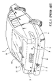
As shown in FIGS. 3 , 4, 5, and 6, the present invention describes a rear lamp set with built in safety sensors. At least one safety sensor 5 is integrated into the lamp set 4. The rear lamp set 4 may be of one-unit type as shown in FIG. 3 , or two-unit type in FIG. 4 . A high mount stop lamp set 7 with built in safety sensors is also described in the invention.
A rear lamp set 4 of the present invention is characterized in that at least one separated chamber 45 is produced at a predetermined position of the back panel 42 and the cover lens 41, and the main body 51 of a safety sensor 5 is directly accommodated in the chamber 45 with the sensor head pointing toward the direction of detection. The safety sensor 5 may be a camera or a distance detecting device. The wires and connectors 52 of the safety sensor 5 could be connected to the wires and cables 43 of the rear lamp set 4 to enable the mounting and wiring of the rear lamp set with built in safety sensors to a vehicle at one time. The number of safety sensors 5 built in the rear lamp set 4 depends on the real need.
As described in FIGS. 3 and 7 , a high mount stop lamp set 7 basically has a cover lens 71, a back panel (rot shown), a light-emitting device, and a full set of wires and connectors (not shown). A chamber 72 of a predetermined size is formed on the cover lens 71 and the back panel to accommodate the main body 51 of a safety sensor 5 therein. Again, the safety sensor 5 may be a camera or a distance detecting device. A high mount stop lamp set 7 with built in safety sensors 5 is particularly suitable for a vehicle having no trunk lid 12.
Some advantages of the present invention are listed in the following:
-
- 1. A rear lamp set 4 and
safety sensors 5 are integrally assembled as a part to simplify the mounting and wiring works to a vehicle. - 2.
Safety sensors 5 are prevented from easy damage, since they are accommodated in rear lamp sets 4 rather than externally hung on body parts or the rear bumper of a vehicle. - 3. Since the mounting and wiring costs can be effectively reduced, a rear lamp set with built in safety sensors according to the present invention may become an origin part of vehicle makers to promote driving safety.
- 4. The present invention may be implemented to rear lamp sets of any type of vehicles, including cars, wagons, vans, buses, trucks, pick-ups, trailers, etc.
- 1. A rear lamp set 4 and
The present invention has been described with a preferred embodiment thereof and it is understood that many changes and modifications in the described embodiment can be carried out without departing from the scope and the spirit of the invention as defined by the appended claims.
Claims (7)
1. A rear lamp set with built-in safety sensors comprising:
a) a back panel having:
i) a plurality of light chambers having a plurality of lamps; and
ii) at least one safety sensor chamber;
b) a cover lens covering the back panel and having:
i) a plurality of lens sections aligning with the plurality of light chambers; and
ii) at least one safety sensor hole aligning with the at least one safety sensor chamber; and
c) at least one safety sensor located in the at least one safety sensor chamber and inserted into the at least one safety sensor hole, the at least one safety sensor having an end aligning with an exterior of the lens cover.
2. The rear lamp set according to claim 1 , wherein the plurality of lamps are selected from a group of lights consisting of a tail lamp, a stop and tail lamp, a turn signal lamp, a backup lamp, a fog lamp, and any combination thereof.
3. The rear lamp set according to claim 1 , wherein each of the back panel and the cover lens are one of a one-piece assembly and a two piece assembly.
4. The rear lamp set according to claim 1 , wherein the at least one safety sensor is one of a camera and a distance detecting device.
5. The rear lamp set according to claim 1 , wherein the plurality of lamps include a backup lamp, the at least one safety sensor includes a set of connectors and wires electrically connected to and activated by the backup lamp.
6. The rear lamp set according to claim 1 , further comprising a high mount stop lamp set having:
a) a plurality of high mount light-emitting devices located therein;
b) a high mount back panel having a first safety sensor chamber;
c) a high mount cover lens having a second safety sensor chamber aligning with the first safety sensor chamber; and
d) at least one high mount safety sensor is located in the first safety sensor chamber and the second safety sensor chamber.
7. The rear lamp set according to claim 6 , wherein the at least one high mount safety sensor is one of a camera and a distance detecting device.
Applications Claiming Priority (2)
| Application Number | Priority Date | Filing Date | Title |
|---|---|---|---|
| TW092205570U TWM245099U (en) | 2003-04-09 | 2003-04-09 | Automobile tail lamp set with safety sensing apparatus |
| TW092205570 | 2003-04-09 |
Publications (2)
| Publication Number | Publication Date |
|---|---|
| US20040201463A1 US20040201463A1 (en) | 2004-10-14 |
| US7068159B2 true US7068159B2 (en) | 2006-06-27 |
Family
ID=29268395
Family Applications (1)
| Application Number | Title | Priority Date | Filing Date |
|---|---|---|---|
| US10/623,529 Expired - Fee Related US7068159B2 (en) | 2003-04-09 | 2003-07-22 | Rear lamp set with built in safety sensors |
Country Status (4)
| Country | Link |
|---|---|
| US (1) | US7068159B2 (en) |
| JP (1) | JP3099374U (en) |
| DE (1) | DE20311415U1 (en) |
| TW (1) | TWM245099U (en) |
Cited By (8)
| Publication number | Priority date | Publication date | Assignee | Title |
|---|---|---|---|---|
| US20070115680A1 (en) * | 2005-11-23 | 2007-05-24 | Chin-Lung Tsai | Third back up light |
| US20080123357A1 (en) * | 2006-02-14 | 2008-05-29 | Hans-Clemens Steffel | Tail light assembly for a motor vehicle |
| US7616102B2 (en) | 2006-11-21 | 2009-11-10 | Ford Global Technologies, Llc | Non-opaque external parking aid sensor bezels |
| US20100315216A1 (en) * | 2009-06-10 | 2010-12-16 | Toyota Motor Engineering & Manufacturing North America, Inc. | Vehicle Warning Systems and Methods |
| US20150109449A1 (en) * | 2010-02-10 | 2015-04-23 | Koito Manufacturing Co., Ltd. | Vehicular lamp with a built-in camera |
| WO2016011125A1 (en) | 2014-07-15 | 2016-01-21 | Huf North America Automotive Parts Mfg. Corp. | Method of verifying user intent in activation of a device in a vehicle |
| US20160159270A1 (en) * | 2014-12-09 | 2016-06-09 | Huf Huelsbeck & Fuerst Gmbh & Co. Kg | Light module for a motor vehicle |
| US10899268B1 (en) * | 2019-12-12 | 2021-01-26 | Hyundai Motor Company | Lamp having built-in sensor, lamp assembly, blind-spot detection system, and blind-spot detection method |
Families Citing this family (8)
| Publication number | Priority date | Publication date | Assignee | Title |
|---|---|---|---|---|
| JP2006231988A (en) * | 2005-02-22 | 2006-09-07 | Nissan Motor Light Truck Co Ltd | Rearview monitor for vehicle |
| US7528703B2 (en) * | 2005-07-26 | 2009-05-05 | Aisin Seiki Kabushiki Kaisha | Obstacle detecting system for vehicle |
| US20090027497A1 (en) | 2007-07-26 | 2009-01-29 | Stephen Thomas Peacock | Camera light |
| DE102008046574A1 (en) * | 2008-09-10 | 2010-03-11 | GM Global Technology Operations, Inc., Detroit | Luggage carrier arrangement for a vehicle rear |
| CN103231742B (en) * | 2013-04-19 | 2016-06-01 | 奇瑞汽车股份有限公司 | Automobile back tail lamp cavity |
| JP6206324B2 (en) * | 2014-05-16 | 2017-10-04 | マツダ株式会社 | Vehicle lamp |
| CN106379225B (en) * | 2016-11-09 | 2018-10-30 | 山东国金汽车制造有限公司 | It is a kind of that there is the taillight with alarm function |
| DE112018007391B4 (en) * | 2018-03-29 | 2023-06-01 | Honda Motor Co., Ltd. | ASTRIDE TYPE VEHICLE |
Citations (6)
| Publication number | Priority date | Publication date | Assignee | Title |
|---|---|---|---|---|
| US6293686B1 (en) * | 1999-02-22 | 2001-09-25 | Koito Manufacturing Co., Ltd. | Lighting device for vehicles |
| US6349251B1 (en) * | 1999-02-15 | 2002-02-19 | Koito Manufacturing Co., Ltd. | Automatic automobile headlamp leveling device |
| US6361196B1 (en) * | 1993-05-14 | 2002-03-26 | Valeo Vision | Electrical module for multiplexed control of a set of lighting or signalling lamps for a motor vehicle |
| US6550949B1 (en) * | 1996-06-13 | 2003-04-22 | Gentex Corporation | Systems and components for enhancing rear vision from a vehicle |
| US6774781B1 (en) * | 2001-08-20 | 2004-08-10 | Kyung Sang Lee | Seatbelt signal light |
| US6909376B2 (en) * | 2002-03-14 | 2005-06-21 | Mark Rennick | Integrated vehicle light and object proximity sensor assembly |
-
2003
- 2003-04-09 TW TW092205570U patent/TWM245099U/en not_active IP Right Cessation
- 2003-07-22 JP JP2003270176U patent/JP3099374U/en not_active Expired - Lifetime
- 2003-07-22 US US10/623,529 patent/US7068159B2/en not_active Expired - Fee Related
- 2003-07-24 DE DE20311415U patent/DE20311415U1/en not_active Expired - Lifetime
Patent Citations (6)
| Publication number | Priority date | Publication date | Assignee | Title |
|---|---|---|---|---|
| US6361196B1 (en) * | 1993-05-14 | 2002-03-26 | Valeo Vision | Electrical module for multiplexed control of a set of lighting or signalling lamps for a motor vehicle |
| US6550949B1 (en) * | 1996-06-13 | 2003-04-22 | Gentex Corporation | Systems and components for enhancing rear vision from a vehicle |
| US6349251B1 (en) * | 1999-02-15 | 2002-02-19 | Koito Manufacturing Co., Ltd. | Automatic automobile headlamp leveling device |
| US6293686B1 (en) * | 1999-02-22 | 2001-09-25 | Koito Manufacturing Co., Ltd. | Lighting device for vehicles |
| US6774781B1 (en) * | 2001-08-20 | 2004-08-10 | Kyung Sang Lee | Seatbelt signal light |
| US6909376B2 (en) * | 2002-03-14 | 2005-06-21 | Mark Rennick | Integrated vehicle light and object proximity sensor assembly |
Cited By (10)
| Publication number | Priority date | Publication date | Assignee | Title |
|---|---|---|---|---|
| US20070115680A1 (en) * | 2005-11-23 | 2007-05-24 | Chin-Lung Tsai | Third back up light |
| US20080123357A1 (en) * | 2006-02-14 | 2008-05-29 | Hans-Clemens Steffel | Tail light assembly for a motor vehicle |
| US7616102B2 (en) | 2006-11-21 | 2009-11-10 | Ford Global Technologies, Llc | Non-opaque external parking aid sensor bezels |
| US20100315216A1 (en) * | 2009-06-10 | 2010-12-16 | Toyota Motor Engineering & Manufacturing North America, Inc. | Vehicle Warning Systems and Methods |
| US8536994B2 (en) | 2009-06-10 | 2013-09-17 | Toyota Motor Engineering & Manufacturing North America, Inc. | Vehicle warning systems and methods |
| US20150109449A1 (en) * | 2010-02-10 | 2015-04-23 | Koito Manufacturing Co., Ltd. | Vehicular lamp with a built-in camera |
| WO2016011125A1 (en) | 2014-07-15 | 2016-01-21 | Huf North America Automotive Parts Mfg. Corp. | Method of verifying user intent in activation of a device in a vehicle |
| US20160159270A1 (en) * | 2014-12-09 | 2016-06-09 | Huf Huelsbeck & Fuerst Gmbh & Co. Kg | Light module for a motor vehicle |
| US9731644B2 (en) * | 2014-12-09 | 2017-08-15 | Huf Huelsbeck & Fuerst Gmbh & Co. Kg | Light module for a motor vehicle |
| US10899268B1 (en) * | 2019-12-12 | 2021-01-26 | Hyundai Motor Company | Lamp having built-in sensor, lamp assembly, blind-spot detection system, and blind-spot detection method |
Also Published As
| Publication number | Publication date |
|---|---|
| TWM245099U (en) | 2004-10-01 |
| DE20311415U1 (en) | 2003-10-16 |
| JP3099374U (en) | 2004-04-02 |
| US20040201463A1 (en) | 2004-10-14 |
Similar Documents
| Publication | Publication Date | Title |
|---|---|---|
| US7068159B2 (en) | Rear lamp set with built in safety sensors | |
| US6840660B2 (en) | High signal lights for automotive vehicles | |
| US6814476B2 (en) | Exterior mirror having an attachment member including an approach light | |
| EP1777943B1 (en) | Multifunctional optical sensor device for driving aids in motor-vehicles | |
| US6977584B2 (en) | Vehicle back up alarm with associated back up light | |
| US20100026475A1 (en) | Exterior rear view mirror with indicator light | |
| US20100129070A1 (en) | Rear view camera mounting on a vehicle | |
| US20070216770A1 (en) | License plate light having attached video camera | |
| US5473515A (en) | Photo-coupled control apparatus for vehicle auxiliary lighting | |
| US5541891A (en) | Distance sensing device | |
| WO2020179577A1 (en) | Vehicle emblem system, vehicle emblem unit, and vehicle emblem attachment unit | |
| JP4566121B2 (en) | Vehicle lighting device | |
| US20230078512A1 (en) | Overhead console accessory system with shared controls, cameras, and lighting | |
| CN113905931A (en) | Tractor video system | |
| JP5329855B2 (en) | Automotive vision support module | |
| US20070171040A1 (en) | Vehicle locator beacon | |
| US7815349B2 (en) | Motor vehicle rear light assembly | |
| JP2007504991A (en) | Device module cover with wall to mount rear view camera | |
| JP4541285B2 (en) | Vehicle lighting system | |
| KR100613553B1 (en) | Exterior mirror with puddle lamp and turn signal lamp | |
| JP2006231988A (en) | Rearview monitor for vehicle | |
| US7322728B2 (en) | Mounting structure for high-mounted stop lamp | |
| CN212373261U (en) | Integrated warning device and outside rearview mirror assembly | |
| CN212373262U (en) | Outside rear-view mirror subassembly and integration warning device thereof | |
| JP2004224088A (en) | Vehicle front end confirmation device |
Legal Events
| Date | Code | Title | Description |
|---|---|---|---|
| FPAY | Fee payment |
Year of fee payment: 4 |
|
| REMI | Maintenance fee reminder mailed | ||
| LAPS | Lapse for failure to pay maintenance fees | ||
| STCH | Information on status: patent discontinuation |
Free format text: PATENT EXPIRED DUE TO NONPAYMENT OF MAINTENANCE FEES UNDER 37 CFR 1.362 |
|
| FP | Lapsed due to failure to pay maintenance fee |
Effective date: 20140627 |