US7080996B2 - Coupling arrangement for subsea electrical power distribution - Google Patents
Coupling arrangement for subsea electrical power distribution Download PDFInfo
- Publication number
- US7080996B2 US7080996B2 US10/704,159 US70415903A US7080996B2 US 7080996 B2 US7080996 B2 US 7080996B2 US 70415903 A US70415903 A US 70415903A US 7080996 B2 US7080996 B2 US 7080996B2
- Authority
- US
- United States
- Prior art keywords
- contact
- coupling part
- coupling
- housing
- contact housing
- Prior art date
- Legal status (The legal status is an assumption and is not a legal conclusion. Google has not performed a legal analysis and makes no representation as to the accuracy of the status listed.)
- Expired - Lifetime
Links
Images


Classifications
-
- H—ELECTRICITY
- H01—ELECTRIC ELEMENTS
- H01R—ELECTRICALLY-CONDUCTIVE CONNECTIONS; STRUCTURAL ASSOCIATIONS OF A PLURALITY OF MUTUALLY-INSULATED ELECTRICAL CONNECTING ELEMENTS; COUPLING DEVICES; CURRENT COLLECTORS
- H01R13/00—Details of coupling devices of the kinds covered by groups H01R12/70 or H01R24/00 - H01R33/00
- H01R13/66—Structural association with built-in electrical component
- H01R13/70—Structural association with built-in electrical component with built-in switch
-
- H—ELECTRICITY
- H01—ELECTRIC ELEMENTS
- H01R—ELECTRICALLY-CONDUCTIVE CONNECTIONS; STRUCTURAL ASSOCIATIONS OF A PLURALITY OF MUTUALLY-INSULATED ELECTRICAL CONNECTING ELEMENTS; COUPLING DEVICES; CURRENT COLLECTORS
- H01R13/00—Details of coupling devices of the kinds covered by groups H01R12/70 or H01R24/00 - H01R33/00
- H01R13/46—Bases; Cases
- H01R13/52—Dustproof, splashproof, drip-proof, waterproof, or flameproof cases
- H01R13/5227—Dustproof, splashproof, drip-proof, waterproof, or flameproof cases with evacuation of penetrating liquids
-
- H—ELECTRICITY
- H01—ELECTRIC ELEMENTS
- H01R—ELECTRICALLY-CONDUCTIVE CONNECTIONS; STRUCTURAL ASSOCIATIONS OF A PLURALITY OF MUTUALLY-INSULATED ELECTRICAL CONNECTING ELEMENTS; COUPLING DEVICES; CURRENT COLLECTORS
- H01R13/00—Details of coupling devices of the kinds covered by groups H01R12/70 or H01R24/00 - H01R33/00
- H01R13/46—Bases; Cases
- H01R13/52—Dustproof, splashproof, drip-proof, waterproof, or flameproof cases
- H01R13/523—Dustproof, splashproof, drip-proof, waterproof, or flameproof cases for use under water
-
- H—ELECTRICITY
- H01—ELECTRIC ELEMENTS
- H01R—ELECTRICALLY-CONDUCTIVE CONNECTIONS; STRUCTURAL ASSOCIATIONS OF A PLURALITY OF MUTUALLY-INSULATED ELECTRICAL CONNECTING ELEMENTS; COUPLING DEVICES; CURRENT COLLECTORS
- H01R13/00—Details of coupling devices of the kinds covered by groups H01R12/70 or H01R24/00 - H01R33/00
- H01R13/46—Bases; Cases
- H01R13/53—Bases or cases for heavy duty; Bases or cases for high voltage with means for preventing corona or arcing
Definitions
- the present invention relates to a coupling arrangement for use in subsea electrical power distribution and a method for connecting a first power conduit to a second power conduit by means of a coupling arrangement.
- This coupling arrangement for use in subsea electrical power distribution is previously known from U.S. Pat. No. 5,834,721 A.
- This coupling arrangement comprises two mutually spaced contact housings mounted in a frame along a common centreline.
- a middle piece is removably mountable in a space between the two contact housings.
- At least one of the contact housings is movable along the centreline towards the middle piece so as to anchor the middle piece in a fluid-tight manner to the contact housings.
- the middle piece is provided with two displaceable contact elements, each of which being displaceable towards and into electrical contact with a contact member of one of the contact housings when the middle piece is in the anchored position.
- a flushing system is adapted to flush sea water out of the internal spaces between the middle piece and the contact housings and fill said spaces with dielectric fluid before said displacement of the contact elements.
- the electrical contact between the contact members does not have to be established until the different parts of the coupling arrangement have been positioned and secured in relation to each other, thereby minimizing the risk of damaging the contact members during the operation of coupling them together.
- the dielectric conditions around the contact members are improved by the flushing operation before the establishment of the electric connection between the contact members.
- the object of the present invention is to provide an improved coupling arrangement for use in subsea electrical power distribution arrangements.
- this object is achieved by a coupling arrangement that includes two main parts: the first coupling part and the second coupling part.
- a contact member arranged in a contact housing of the first coupling part is connectable to a contact member arranged in a contact housing of the second coupling part by means of a displaceable contact element arranged in one of the coupling parts. Consequently, no middle piece has to be inserted between the two contact housings in order to establish the electric connection between the two contact members.
- the electric connection between the two contact members is established by the displacement of only one displaceable contact element, in contrast to the coupling arrangement according to U.S. Pat. No. 5,834,721 A where the displacement of two displaceable contact elements is required.
- the present invention offers a coupling arrangement having a simpler construction and being easier to operate, as compared to the coupling arrangement previously known from U.S. Pat. No. 5,834,721 A.
- the inventive coupling arrangement could be used for coupling together two power conduits in the form of power cables.
- the inventive coupling arrangement could also be used for coupling together a first power conduit in the form of a power cable and a second power conduit constituting another type of power conduit than a power cable or coupling together two power conduits constituting other types of power conduits than power cables.
- One of said power conduits could for instance be an input terminal or an output terminal of an electrical appliance.
- the second coupling part is adapted to be mounted to the first coupling part by being lowered down vertically into engagement with the first coupling part and demounted from the first coupling part by being lifted vertically out of engagement therewith.
- the two coupling parts can be mounted to and demounted from each other in a very simple manner.
- the second coupling part is positionable in an intermediate position in contact with the first coupling part by being lowered down vertically into engagement therewith, the second contact housing being movable in relation to the first contact housing when the second coupling part is positioned in said intermediate position so as to secure the second contact housing in a fluid-tight manner to the first contact housing. Consequently, the coupling parts are mounted to each other in a first operation and the contact housings are secured to each other in a subsequent operation. In this way, the contact housings are positioned in relation to each other before they are mutually moved and secured to each other, thereby minimizing the risk of damaging the contact housings during the operation of securing them together.
- the coupling arrangement comprises a mounting tool, which is removably mountable to the second coupling part, said mounting tool being adapted to actuate the movement of the second contact housing in relation to the first contact housing so as to secure the second contact housing in a fluid-tight manner to the first contact housing. Consequently, the means for performing the operation of securing the contact housings together are at least partly accommodated in the mounting tool separate from the two coupling parts, thereby allowing a simpler, more compact and more durable construction of said coupling parts as compared to an embodiment having said means incorporated in the coupling parts.
- a watertight metal seal is arranged between the contact housings so as to seal the space between the contact housings from the surrounding sea water when the contact housings have been secured to each other.
- said metal seal should be of corrosion resistant metal material.
- elastomer seals have shown signs of degradation in the course of time due to ageing, which may result in loss of flexibility and cause water ingress, the latter of which may be detrimental to the dielectric property of the connector internals. This problem is eliminated by the use of metal seals.
- the coupling arrangement is provided with a flushing system for flushing sea water out of the space between the first contact housing and the second contact housing and filling said space with dielectric fluid when the contact housings have been secured to each other in a fluid-tight manner.
- a flushing system for flushing sea water out of the space between the first contact housing and the second contact housing and filling said space with dielectric fluid when the contact housings have been secured to each other in a fluid-tight manner.
- a flushing device included in the flushing system and adapted to actuate the flushing out of sea water and the filling with dielectric fluid is arranged in a separate mounting tool. Consequently, means for actuating the flushing operation are accommodated in the mounting tool separate from the two coupling parts, thereby allowing a simpler, more compact and more durable construction of said coupling parts as compared to an embodiment having said means incorporated in the coupling parts.
- the mounting tool accommodates the dielectric fluid to be used for said filling.
- the dielectric fluid to be used for said filling.
- the contact housing accommodating the contact element is provided with a chamber, the contact element being supported by a piston, which is mounted in said chamber and which is adapted to be hydraulically actuated so as to achieve said displacement of the contact element.
- the displacement of the contact element is accomplished in a simple and reliable manner.
- said flushing system is adapted to control the conditioning of the dielectric properties in the space of the dielectric fluid between the first contact housing and the second contact housing.
- the resulting dielectric level of said conditioning is preferably verifiable through insulation resistance measurements, the acceptance of the latter being within the minimum requirements in order to commence the actual mating of the contact members.
- a device adapted to control the hydraulic pressure in said chamber so as to control said displacement of the contact element is arranged in a separate mounting tool. Consequently, means for controlling the displacement of the contact element are accommodated in the mounting tool separate from the two coupling parts, thereby allowing a simpler, more compact and more durable construction of said coupling parts as compared to an embodiment having the coupling parts pre-filled with dielectric fluid, the contamination of the latter during connection, is beyond means of replacement of the dielectric fluid.
- the mounting tool is adapted to be mounted to the second coupling part by being lowered down vertically into engagement therewith and demounted from the second coupling part by being lifted vertically out of engagement therewith. In this way, the mounting tool can be mounted to and demounted from the second coupling part in a very simple manner.
- the invention also relates to a method for connecting a first power conduit to a second power conduit by means of the inventive coupling arrangement.
- FIG. 1 is a schematical illustration of a coupling arrangement according to an embodiment of the present invention, with the two coupling parts of the coupling arrangement out of engagement with each other,
- FIG. 2 is a schematical illustration of the coupling arrangement of FIG. 1 , with the second coupling part in contact with the first coupling part during lowering of the former into the latter,
- FIG. 3 is a schematical illustration of the coupling arrangement of FIGS. 1 and 2 , with a mounting tool mounted to the second coupling part,
- FIG. 4 is a schematical partial view of the coupling arrangement of FIGS. 1–3 , illustrating the two contact housings secured to each other,
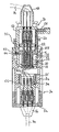
- FIG. 5 is a schematical cross-sectional view illustrating a coupling arrangement according to a preferred embodiment of the invention, with the second coupling part positioned in an intermediate position in contact with the first coupling part,
- FIG. 6 is a schematical cross-sectional view illustrating the coupling arrangement of FIG. 5 , with the two contact housings secured to each other, and
- FIG. 7 is a schematical partial view illustrating the coupling arrangement of FIGS. 5 and 6 after the establishment of electric connection between the contact members of the two coupling parts.
- FIGS. 1–4 illustrates a coupling arrangement 1 according to an embodiment of the present invention.
- This coupling arrangement 1 is designed for use in subsea electrical power distribution and comprises a first coupling part 1 a and a second coupling part 1 b , which are removably securable to each other.
- a first power conduit 7 a is connected to the first coupling part 1 a and a second power conduit 7 b is connected to the second coupling part 1 b .
- the two power conduits 7 a , 7 b are connectable to each other by means of the coupling arrangement 1 .
- the respective power conduit 7 a , 7 b here constitutes a power cable.
- Each coupling part 1 a , 1 b is provided with a contact housing 2 a , 2 b accommodating a respective contact member, not shown in FIGS. 1–4 .
- the coupling parts 1 a , 1 b are so designed that a gap is provided between the contact member of the first coupling part 1 a and the contact member of the second coupling part 1 b when the contact housings 2 a , 2 b are secured to each other.
- the contact housing 1–4 is displaceably arranged in the contact housing 2 a , 2 b of one of the coupling parts 1 a , 1 b so as to be displaceable towards the contact member of the other coupling part, when the contact housings 2 a , 2 b are secured to each other, from a first position, in which no electric connection between the contact member of the first coupling part 1 a and the contact member of the second coupling part 1 b is established by the contact element, and into a second position, in which the contact element is establishing electric connection between said contact members.
- the displacement of the contact element is preferably hydraulically actuated.
- the contact housing 2 a of the first coupling part 1 a is preferably positioned with its centre axis vertically arranged, as illustrated in FIG. 1 .
- the first coupling part 1 a which here constitutes a lower coupling part, is e.g. attached to a foundation structure, not shown, which is secured to a structure placed on the seabed.
- the second coupling part 1 b which here constitutes an upper coupling part, is part of typically an electrical drive module.
- the second coupling part 1 b is in this case adapted to be mounted to the first coupling part 1 a by being lowered down vertically into engagement with the first coupling part 1 a and demounted from the first coupling part 1 a by being lifted vertically out of engagement therewith.
- the lowering and lifting operations are e.g. carried out by means of a winch device arranged on a ship or on a platform and connected to the electrical drive module, which includes the second coupling part 1 b , by use of a rope or wire.
- the contact housing 2 a of the first coupling part 1 a has a cavity 6 for receiving an end part 8 of the other contact housing 2 b . Consequently, the contact housing 2 a is designed as a female-like member and the other contact housing 2 b as a male-like member. It is of course also possible to design the contact housing 2 a of the first coupling part 1 a as a male-like member and the other contact housing 2 b as a female-like member, if so desired.
- the second coupling part 1 b is positionable in an intermediate position in contact with the first coupling part 1 a by being lowered down vertically into engagement therewith, the contact housing 2 b of the second coupling part 1 b being movable in relation to the contact housing 2 a of the first coupling part 1 a when the second coupling part 1 b is positioned in said intermediate position so as to secure the contact housings 2 a , 2 b in a fluid-tight manner to each other.
- the coupling parts 1 a , 1 b are provided with a locking device 40 , which is adapted to support the second coupling part 1 b in relation to the first coupling part 1 a in said intermediate position and allow the second coupling part 1 b to descend in relation to the first coupling part 1 a from said intermediate position.
- the contact housing 2 b of the second coupling part 1 b is made to descend in relation to the contact housing 2 a of the first coupling part 1 a .
- the locking device 40 is also adapted to secure the contact housings 2 a , 2 b to each other when the second coupling part 1 b has been allowed to descend from the intermediate position.
- the locking device is preferably hydraulically actuated.
- the locking device 40 comprises a number of pivotal locking members 41 arranged around the end part 8 of the contact housing 2 b of the second coupling part 1 b , which are adapted to co-operate with corresponding locking members in the form of pivot member locking surfaces 43 and grooves 42 arranged in the cavity 6 of the first coupling part 1 a .
- the coupling arrangement 1 could also be provided with suitable damping devices for absorbing the impacts between the coupling parts when the second coupling part 1 b descends in relation to the first coupling part 1 a.
- the coupling arrangement 1 is illustrated with the second coupling part 1 b positioned in the intermediate position in contact with the first coupling part 1 a . In this position, the second coupling part 1 b is resting in a high, intermediate parking position by the function of a mechanical latch, not shown, through the above-mentioned locking device 40 .
- the coupling arrangement 1 is illustrated with the two contact housings 2 a , 2 b secured to each other in a fluid-tight manner, i.e. after the second coupling part 1 b has been descended in relation to the first coupling part 1 a from the intermediate position.
- the coupling arrangement preferably comprises a mounting tool 30 , which is removably mountable to the second coupling part 1 b , said mounting tool 30 being adapted to actuate the locking device 40 so as to allow the second coupling part 1 b to descend in relation to the first coupling part 1 a as indicated above.
- the mounting tool 30 is adapted to be mounted to the second coupling part 1 b by being lowered down vertically into engagement therewith and demounted from the second coupling part 1 b by being lifted vertically out of engagement therewith.
- the lowering and lifting operations are e.g. carried out by means of a winch device arranged on a ship or on a platform and connected to the mounting tool 30 through a rope or wire.
- FIG. 3 shows the coupling arrangement 1 with the mounting tool 30 mounted on top of the second coupling part 1 b .
- the mounting tool 30 is hydraulically connected to the second coupling part 1 b through a hydraulic connection 50 so as to allow a number of operations on the second coupling part 1 b to be hydraulically actuated by the mounting tool 30 .
- the hydraulic connection 50 comprises a connection part 51 associated with the mounting tool 30 and a corresponding connection part 52 associated with the second coupling part 1 b .
- the connection part 51 associated with the mounting tool 30 is preferably moveable in relation to the remaining part of the mounting tool and adapted to be connected to the other connection part 52 by being lowered down vertically into engagement therewith after the mounting tool 30 has been brought into engagement with the second coupling part 1 b.
- FIG. 5 shows the second coupling part 1 b positioned in the intermediate position, from which part 1 b is vertically lowered down onto contact with the first coupling part 1 a .
- FIG. 6 shows the coupling arrangement after the actuation of the locking device 40 , i.e. after the contact housing 2 b of the second coupling part 1 b has been moved in relation to the contact housing 2 a of the first coupling part 1 a so as to secure the two contact housings 2 a , 2 b to each other in a fluid-tight manner.
- FIG. 5 shows the second coupling part 1 b positioned in the intermediate position, from which part 1 b is vertically lowered down onto contact with the first coupling part 1 a .
- FIG. 6 shows the coupling arrangement after the actuation of the locking device 40 , i.e. after the contact housing 2 b of the second coupling part 1 b has been moved in relation to the contact housing 2 a of the first coupling part 1 a so as to secure the two contact
- the contact element 10 is in the previously mentioned first position, in which no electric connection between the contact member 3 a of the first coupling part 1 a and the contact member 3 b of the second coupling part 1 b is established by the contact element.
- FIG. 7 shows the contact element 10 positioned in the previously mentioned second position, in which the contact element is establishing electric connection between said contact members 3 a , 3 b.
- the contact housing 2 a of the first coupling part 1 a will be denominated the first contact housing and the contact housing 2 b of the second coupling part 1 b will be denominated the second contact housing.
- the contact member 3 a of the first coupling part 1 a will be denominated the first contact member and the contact member 3 b of the second coupling part 1 b will be denominated the second contact member.
- the first coupling part 1 a is provided with an attachment 4 a for the first power conduit 7 a and the second coupling part 1 b is provided with an attachment 4 b for the second power conduit 7 b .
- the contact members 3 a , 3 b are arranged in the respective contact housing 2 a , 2 b partly surrounded by a chamber 5 a , 5 b filled with dielectric fluid.
- Compensators are suitably arranged in said chambers 5 a , 5 b for counter-balancing hydrostatic pressure and for taking care of volumetric compensation in connection with expansion/contraction of the dielectric fluid.
- the compensators preferably comprise metallic bellows, but may also be made of elastomer materials.
- the respective contact member 3 a , 3 b comprises three contact pins 13 a , 13 b .
- the contact element 10 here comprises three contact sleeves 11 , each of which being positionable around and in electric contact with two opposed contact pins 13 a , 13 b of the two contact members 3 a , 3 b .
- the contact sleeves 11 are preferably integrated into one single unit, as illustrated in FIGS. 5–7 .
- the contact element 10 is here accommodated in the second contact housing 2 b .
- the contact element 10 is supported by a piston 24 displaceably mounted in a chamber 22 arranged in the second contact housing 2 b .
- Said chamber 22 is preferably filled with dielectric fluid.
- the piston 24 is adapted to be hydraulically actuated so as to achieve the displacement of the contact element 10 between the above-mentioned first and second positions.
- the above-mentioned mounting tool 30 preferably comprises a device adapted to control the hydraulic pressure in said chamber 22 so as to control the displacement of the contact element 10 .
- the chamber 22 is connected to the mounting tool 30 via hydraulic channels 54 arranged in the second coupling part 1 b and via the hydraulic connection 50 .
- FIG. 7 shows the contact element 10 when positioned in said second position, i.e. when establishing electric connection between the first contact member 3 a and the second contact member 3 b.
- a securing member 44 is adapted to secure the locking members 41 in the position indicated in FIG. 6 and FIG. 7 .
- a securing member 44 is adapted to secure the locking members 41 in the position indicated in FIG. 5 .
- the securing member 44 is displaceably arranged in the second coupling part 1 b and the displacement thereof is hydraulically actuated by means of the mounting tool 30 .
- the locking members 41 are pivotally mounted to the second coupling part 1 b .
- the locking members 41 are free to pivot so as to allow the second coupling part 1 b and thereby the second contact housing 2 b to move downwards into the cavity 6 of the first coupling part 1 a until a ring-shaped metal seal 12 of one of the contact housings abuts against a corresponding sealing surface 15 of the other contact housing.
- the metal seal 12 is mounted to the second contact housing 2 b and the first contact housing 2 a is provided with a recess 15 for receiving the metal seal.
- the metal seal 12 seals the space 14 between the contact housings 2 a , 2 b from the surrounding sea water when the contact housings 2 a , 2 b have been secured to each other.
- the contact housings 2 a , 2 b are secured to each other by means of the locking device 40 in that the securing member 44 is displaced upwards in relation to the second coupling part 1 b so as to secure the locking members 41 inside a groove 42 arranged in the cavity 6 .
- the coupling arrangement 1 is provided with a flushing system for flushing sea water out of the space 14 between the contact housings 2 a , 2 b and filling said space 14 with dielectric fluid when the contact housings 2 a , 2 b have been secured to each other in a fluid-tight manner.
- the above-mentioned mounting tool 30 is used for carrying out these flushing and filling operations.
- the mounting tool 30 comprises a flushing device included in the flushing system.
- the flushing system is adapted to perform replacement of the sea water with a dielectric fluid through a flushing sequence, which involves a scheme of sequential flushing of flushing fluids via the hydraulic channels 55 indicated by CA (flushing in), CB and CC (flushing out) in FIG. 5 .
- Said flushing system is also adapted to perform conditioning of the dielectric properties or level of the dielectric fluid entrapped in space 14 , i.e. in the volume between the first contact housing 2 a and the second contact housing 2 b .
- the conditioning of the dielectric properties is preferably actively controlled by measurements by means of the flushing system.
- the mounting tool 30 accommodates the dielectric fluid to be used for said filling.
- the space 14 is connected to the mounting tool 30 via hydraulic channels 55 arranged in the second coupling part 1 b and via the hydraulic connection 50 .
- the dielectric properties inside the contact housings 2 a , 2 b is determined by measurements performed after said filling with dielectric fluid and before said displacement of the contact element 10 .
- the determination of the dielectric properties inside the contact housings 2 a , 2 b is for instance determined based on measurements of the insulation resistance between the respective electric phase and phase ground.
- the resulting dielectric level of said conditioning is verifiable through the insulation resistance measurements, the acceptance of the latter should be within the minimum requirements so as to establish a non-conducting environment of the space 14 in order to commence the actual mating of the contact members 3 a , 3 b .
- the dielectric properties or level around the contact members 3 a , 3 b can be determined and recorded or documented, as compared to prior art embodiments having no means or method for providing such documentation prior to applying service voltage and current. Said measurements are preferably performed with the aid of the mounting tool 30 .
- the mounting tool 30 is suitably removed from the second coupling part 1 b.
- the inventive coupling arrangement 1 it is also possible to disconnect the two power conduits 7 a , 7 b electrically from each other without any mutual separation of the contact housings 2 a , 2 b .
- This displacement of the contact element 10 may be suitably remotely controlled through an electro-hydraulic control arrangement connected to the second coupling part via the connection part 52 .
- the control arrangement is connected to the second coupling part 1 b after the removal of the mounting tool 30 therefrom.
- the above-mentioned dielectric fluid is the end product of the above-mentioned flushing sequence, which typically may involve the following three fluids the one replacing the other: sea water replaced by desalinated water (fluid no. 1), to be replaced by ethanol (fluid no. 2), which finally is replaced by the dielectric oil (fluid no. 3).
- a typical area of use for the present invention is a subsea installation for separation of water from crude oil, in which supplied hydraulic or electrical power is required in order to facilitate re-injection of separated water by operation of injection pumps. Electrical power must in such a case be supplied through an electrical system facilitating high voltage transfer from a surface installation to the subsea installation.
Abstract
Description
Claims (25)
Applications Claiming Priority (2)
| Application Number | Priority Date | Filing Date | Title |
|---|---|---|---|
| NO20025425 | 2002-11-12 | ||
| NO20025425A NO317145B1 (en) | 2002-11-12 | 2002-11-12 | A coupling device |
Publications (2)
| Publication Number | Publication Date |
|---|---|
| US20040137773A1 US20040137773A1 (en) | 2004-07-15 |
| US7080996B2 true US7080996B2 (en) | 2006-07-25 |
Family
ID=19914168
Family Applications (1)
| Application Number | Title | Priority Date | Filing Date |
|---|---|---|---|
| US10/704,159 Expired - Lifetime US7080996B2 (en) | 2002-11-12 | 2003-11-10 | Coupling arrangement for subsea electrical power distribution |
Country Status (3)
| Country | Link |
|---|---|
| US (1) | US7080996B2 (en) |
| GB (1) | GB2398182B (en) |
| NO (1) | NO317145B1 (en) |
Cited By (9)
| Publication number | Priority date | Publication date | Assignee | Title |
|---|---|---|---|---|
| US20060260817A1 (en) * | 2005-05-21 | 2006-11-23 | Schlumberger Technology Corporation | Downhole Connection System |
| US20070107907A1 (en) * | 2005-11-15 | 2007-05-17 | Schlumberger Technology Corporation | System and Method for Controlling Subsea Wells |
| US20090284901A1 (en) * | 2006-07-05 | 2009-11-19 | Vetco Gray Scandinavia As | Subsea switchgear apparatus |
| US20100220431A1 (en) * | 2008-09-15 | 2010-09-02 | Viper Subsea Limited | Subsea Protection Device |
| US20100270032A1 (en) * | 2009-04-23 | 2010-10-28 | Vetco Gray Inc. | System, method and apparatus for thermal wellhead having high power cable for in-situ upgrading processing |
| US20110150394A1 (en) * | 2008-08-14 | 2011-06-23 | Soerensen Per Hassel | Housing for wet-mateable connector and penetrator assembly |
| US20120117793A1 (en) * | 2009-07-03 | 2012-05-17 | Centre National De La Recherche Scientifique | Connection device for a submersible connector |
| EP2520757A2 (en) | 2011-05-03 | 2012-11-07 | Vetco Gray Scandinavia AS | A method for connecting two coupling parts of a subsea coupling arrangement to each other |
| EP3164747A1 (en) * | 2014-07-02 | 2017-05-10 | Teledyne Instruments, Inc. | Non-pressure compensated, wet-mateable plug for feedthrough and other subsea systems |
Families Citing this family (4)
| Publication number | Priority date | Publication date | Assignee | Title |
|---|---|---|---|---|
| NO327370B1 (en) * | 2007-07-03 | 2009-06-15 | Vetco Gray Scandinavia As | Device adapted for a submarine application |
| DE102010045523A1 (en) * | 2010-09-15 | 2012-03-15 | Hilde Schlögl | Coupling arrangement and coupling piece |
| DE102011081977A1 (en) * | 2011-09-01 | 2013-03-07 | Endress + Hauser Process Solutions Ag | Plug for use with socket for connecting Ethernet cables, has housing receiving electrical plug-in contact and comprising internal and external screw threads for moving electrical plug-in contact along longitudinal axis of housing |
| GB2501249B (en) * | 2012-04-16 | 2014-08-06 | Tidal Generation Ltd | Water-based power generation installations |
Citations (8)
| Publication number | Priority date | Publication date | Assignee | Title |
|---|---|---|---|---|
| US4073562A (en) | 1976-08-30 | 1978-02-14 | Gray Tool Company | Wet connector |
| GB1577850A (en) | 1977-08-25 | 1980-10-29 | Ferranti Ltd | Electrical connectors |
| GB2104305A (en) | 1981-05-20 | 1983-03-02 | British Underwater Pipeline | Improvements in or relating to the introduction of liquids into underwater cavities |
| US4472611A (en) | 1981-12-21 | 1984-09-18 | Societe D'exploitation Des Procedes Marechal (Sepm) | Current supply connector comprising a plug socket with pivotal contact-strips and a plug with a push-rod unit |
| US4553000A (en) | 1983-11-14 | 1985-11-12 | Appleton Electric Company | Plug and receptacle with separable switch contactors |
| US5073125A (en) | 1989-04-07 | 1991-12-17 | Japan Aviation Electronics Industry, Limited | Electrical connector comprising an intermediate connection element for connecting and disconnecting between a first and second connection element |
| US5738535A (en) * | 1996-03-07 | 1998-04-14 | Ocean Design, Inc. | Underwater connector |
| US5834721A (en) | 1996-11-13 | 1998-11-10 | Abb Offshore Technology As | Coupling- and switch system for subsea electrical power distribution |
-
2002
- 2002-11-12 NO NO20025425A patent/NO317145B1/en not_active IP Right Cessation
-
2003
- 2003-11-07 GB GB0326143A patent/GB2398182B/en not_active Expired - Fee Related
- 2003-11-10 US US10/704,159 patent/US7080996B2/en not_active Expired - Lifetime
Patent Citations (8)
| Publication number | Priority date | Publication date | Assignee | Title |
|---|---|---|---|---|
| US4073562A (en) | 1976-08-30 | 1978-02-14 | Gray Tool Company | Wet connector |
| GB1577850A (en) | 1977-08-25 | 1980-10-29 | Ferranti Ltd | Electrical connectors |
| GB2104305A (en) | 1981-05-20 | 1983-03-02 | British Underwater Pipeline | Improvements in or relating to the introduction of liquids into underwater cavities |
| US4472611A (en) | 1981-12-21 | 1984-09-18 | Societe D'exploitation Des Procedes Marechal (Sepm) | Current supply connector comprising a plug socket with pivotal contact-strips and a plug with a push-rod unit |
| US4553000A (en) | 1983-11-14 | 1985-11-12 | Appleton Electric Company | Plug and receptacle with separable switch contactors |
| US5073125A (en) | 1989-04-07 | 1991-12-17 | Japan Aviation Electronics Industry, Limited | Electrical connector comprising an intermediate connection element for connecting and disconnecting between a first and second connection element |
| US5738535A (en) * | 1996-03-07 | 1998-04-14 | Ocean Design, Inc. | Underwater connector |
| US5834721A (en) | 1996-11-13 | 1998-11-10 | Abb Offshore Technology As | Coupling- and switch system for subsea electrical power distribution |
Cited By (17)
| Publication number | Priority date | Publication date | Assignee | Title |
|---|---|---|---|---|
| US7503395B2 (en) * | 2005-05-21 | 2009-03-17 | Schlumberger Technology Corporation | Downhole connection system |
| US20060260817A1 (en) * | 2005-05-21 | 2006-11-23 | Schlumberger Technology Corporation | Downhole Connection System |
| US20070107907A1 (en) * | 2005-11-15 | 2007-05-17 | Schlumberger Technology Corporation | System and Method for Controlling Subsea Wells |
| US7931090B2 (en) * | 2005-11-15 | 2011-04-26 | Schlumberger Technology Corporation | System and method for controlling subsea wells |
| US20090284901A1 (en) * | 2006-07-05 | 2009-11-19 | Vetco Gray Scandinavia As | Subsea switchgear apparatus |
| US7952855B2 (en) * | 2006-07-05 | 2011-05-31 | Vetco Gray Scandinavia As | Subsea switchgear apparatus |
| US20110150394A1 (en) * | 2008-08-14 | 2011-06-23 | Soerensen Per Hassel | Housing for wet-mateable connector and penetrator assembly |
| US8483530B2 (en) | 2008-08-14 | 2013-07-09 | Roxar Flow Measurement As | Housing for wet-mateable connector and penetrator assembly |
| US20100220431A1 (en) * | 2008-09-15 | 2010-09-02 | Viper Subsea Limited | Subsea Protection Device |
| US8186445B2 (en) * | 2009-04-23 | 2012-05-29 | Vetco Gray Inc. | System, method and apparatus for thermal wellhead having high power cable for in-situ upgrading processing |
| US20100270032A1 (en) * | 2009-04-23 | 2010-10-28 | Vetco Gray Inc. | System, method and apparatus for thermal wellhead having high power cable for in-situ upgrading processing |
| US20120117793A1 (en) * | 2009-07-03 | 2012-05-17 | Centre National De La Recherche Scientifique | Connection device for a submersible connector |
| US9136638B2 (en) * | 2009-07-03 | 2015-09-15 | Centre National De La Recherche Scientifique | Connection device for a submersible connector |
| EP2520757A2 (en) | 2011-05-03 | 2012-11-07 | Vetco Gray Scandinavia AS | A method for connecting two coupling parts of a subsea coupling arrangement to each other |
| US20120279718A1 (en) * | 2011-05-03 | 2012-11-08 | Svend Erik Rocke | Method for connecting two coupling parts of a subsea coupling arrangement to each other |
| US9010434B2 (en) * | 2011-05-03 | 2015-04-21 | Vetco Gray Scandinavia As | Method for connecting two coupling parts of a subsea coupling arrangement to each other |
| EP3164747A1 (en) * | 2014-07-02 | 2017-05-10 | Teledyne Instruments, Inc. | Non-pressure compensated, wet-mateable plug for feedthrough and other subsea systems |
Also Published As
| Publication number | Publication date |
|---|---|
| NO317145B1 (en) | 2004-08-23 |
| GB2398182B (en) | 2006-06-07 |
| US20040137773A1 (en) | 2004-07-15 |
| GB2398182A (en) | 2004-08-11 |
| NO20025425D0 (en) | 2002-11-12 |
| GB0326143D0 (en) | 2003-12-17 |
Similar Documents
| Publication | Publication Date | Title |
|---|---|---|
| EP2520757B1 (en) | A method for connecting two coupling parts of a subsea coupling arrangement to each other | |
| US7080996B2 (en) | Coupling arrangement for subsea electrical power distribution | |
| US6200152B1 (en) | Electrical connection | |
| CA2355547C (en) | Multi-contact, wet-mateable, electrical connector | |
| US4363168A (en) | Method of forming an electrical connection underwater | |
| EP0515513B1 (en) | Releasable hydraulic and/or electric connection for subsea equipment | |
| US8286712B2 (en) | Deploying an electrically-activated tool into a subsea well | |
| US6974341B2 (en) | Subsea well electrical connector | |
| EP0454717B1 (en) | Subsea electrical conductive insert coupling | |
| EP3638873B1 (en) | Subsea electric power and communication module | |
| US5834721A (en) | Coupling- and switch system for subsea electrical power distribution | |
| US11875918B2 (en) | Electrical feedthrough system and methods of use thereof | |
| WO1998021785A9 (en) | A coupling- and switch system for subsea electrical power distribution | |
| EP3927931B1 (en) | Electrical feedthrough system and methods of use thereof |
Legal Events
| Date | Code | Title | Description |
|---|---|---|---|
| AS | Assignment |
Owner name: ABB AS, NORWAY Free format text: ASSIGNMENT OF ASSIGNORS INTEREST;ASSIGNOR:OSTERGAARD, INGE;REEL/FRAME:014849/0243 Effective date: 20031111 |
|
| AS | Assignment |
Owner name: ABB OFFSHORE SYSTEMS AS, NORWAY Free format text: ASSIGNMENT OF ASSIGNORS INTEREST;ASSIGNOR:ABB AS;REEL/FRAME:015864/0381 Effective date: 20040219 |
|
| AS | Assignment |
Owner name: J.P. MORGAN EUROPE LIMITED, AS SECURITY AGENT, UNI Free format text: SECURITY AGREEMENT;ASSIGNOR:ABB OFFSHORE SYSTEMS INC.;REEL/FRAME:015215/0872 Effective date: 20040712 |
|
| AS | Assignment |
Owner name: VETCO AIBEL AS, NORWAY Free format text: CHANGE OF NAME;ASSIGNOR:ABB OFFSHORE SYSTEMS AS;REEL/FRAME:017516/0338 Effective date: 20040717 |
|
| STCF | Information on status: patent grant |
Free format text: PATENTED CASE |
|
| AS | Assignment |
Owner name: VETCO GRAY SCANDINAVIA AS,NORWAY Free format text: ASSIGNMENT OF ASSIGNORS INTEREST;ASSIGNOR:VETCO AIBEL AS;REEL/FRAME:019055/0021 Effective date: 20070214 Owner name: VETCO GRAY SCANDINAVIA AS, NORWAY Free format text: ASSIGNMENT OF ASSIGNORS INTEREST;ASSIGNOR:VETCO AIBEL AS;REEL/FRAME:019055/0021 Effective date: 20070214 |
|
| AS | Assignment |
Owner name: VETCO GRAY CONTROLS INC. (ABB OFFSHORE SYSTEMS INC Free format text: GLOBAL DEED OF RELEASE;ASSIGNOR:J.P. MORGAN EUROPE LIMITED;REEL/FRAME:019795/0479 Effective date: 20070223 |
|
| FPAY | Fee payment |
Year of fee payment: 4 |
|
| FEPP | Fee payment procedure |
Free format text: PAYOR NUMBER ASSIGNED (ORIGINAL EVENT CODE: ASPN); ENTITY STATUS OF PATENT OWNER: LARGE ENTITY |
|
| FPAY | Fee payment |
Year of fee payment: 8 |
|
| MAFP | Maintenance fee payment |
Free format text: PAYMENT OF MAINTENANCE FEE, 12TH YEAR, LARGE ENTITY (ORIGINAL EVENT CODE: M1553) Year of fee payment: 12 |