US7108559B2 - Router with field replaceable motherboard - Google Patents

Router with field replaceable motherboard Download PDF

Info

Publication number
US7108559B2
US7108559B2 US11/020,733 US2073304A US7108559B2 US 7108559 B2 US7108559 B2 US 7108559B2 US 2073304 A US2073304 A US 2073304A US 7108559 B2 US7108559 B2 US 7108559B2
Authority
US
United States
Prior art keywords
motherboard
slot
midplane
router
connectors
Prior art date
Legal status (The legal status is an assumption and is not a legal conclusion. Google has not performed a legal analysis and makes no representation as to the accuracy of the status listed.)
Expired - Fee Related
Application number
US11/020,733
Other versions
US20050117282A1 (en
Inventor
Helen Shtargot
Dattatri Mattur
Shawn Bender
William J. Lewis
Lwin Tint
David Tarkington
Ming Chi Chen
Rene Duzac
James Everett Grishaw
Torence Lu
Kimberly Rae Turner
Phong Hoang Ho
Robert A. Loose
Stephen Scearce
Current Assignee (The listed assignees may be inaccurate. Google has not performed a legal analysis and makes no representation or warranty as to the accuracy of the list.)
Cisco Technology Inc
Original Assignee
Cisco Technology Inc
Priority date (The priority date is an assumption and is not a legal conclusion. Google has not performed a legal analysis and makes no representation as to the accuracy of the date listed.)
Filing date
Publication date
Priority claimed from US10/227,472 external-priority patent/US6796843B1/en
Application filed by Cisco Technology Inc filed Critical Cisco Technology Inc
Priority to US11/020,733 priority Critical patent/US7108559B2/en
Assigned to CISCO TECHNOLOGY, INC. reassignment CISCO TECHNOLOGY, INC. ASSIGNMENT OF ASSIGNORS INTEREST (SEE DOCUMENT FOR DETAILS). Assignors: SCEARCE, STEPHEN, HO, PHONG HOANG, BENDER, SHAWN, CHEN, MING CHI, DUZAC, RENE, GRISHAW, JAMES EVERETT, LEWIS, WILLIAM J., LOOSE, ROBERT A., LU, TORENCE, MATTUR, DATTATRI, SHTARGOT, HELEN, TARKINGTON, DAVID, TINT, LWIN, TURNER, KIMBERLY RAE
Publication of US20050117282A1 publication Critical patent/US20050117282A1/en
Assigned to CISCO TECHNOLOGY, INC. reassignment CISCO TECHNOLOGY, INC. ASSIGNMENT OF ASSIGNORS INTEREST (SEE DOCUMENT FOR DETAILS). Assignors: CRUSE, TERRI
Priority to US11/523,320 priority patent/US7285022B2/en
Application granted granted Critical
Publication of US7108559B2 publication Critical patent/US7108559B2/en
Anticipated expiration legal-status Critical
Expired - Fee Related legal-status Critical Current

Links

Images

Classifications

    • HELECTRICITY
    • H05ELECTRIC TECHNIQUES NOT OTHERWISE PROVIDED FOR
    • H05KPRINTED CIRCUITS; CASINGS OR CONSTRUCTIONAL DETAILS OF ELECTRIC APPARATUS; MANUFACTURE OF ASSEMBLAGES OF ELECTRICAL COMPONENTS
    • H05K7/00Constructional details common to different types of electric apparatus
    • H05K7/14Mounting supporting structure in casing or on frame or rack
    • H05K7/1438Back panels or connecting means therefor; Terminals; Coding means to avoid wrong insertion
    • H05K7/1439Back panel mother boards
    • H05K7/1445Back panel mother boards with double-sided connections
    • HELECTRICITY
    • H01ELECTRIC ELEMENTS
    • H01RELECTRICALLY-CONDUCTIVE CONNECTIONS; STRUCTURAL ASSOCIATIONS OF A PLURALITY OF MUTUALLY-INSULATED ELECTRICAL CONNECTING ELEMENTS; COUPLING DEVICES; CURRENT COLLECTORS
    • H01R12/00Structural associations of a plurality of mutually-insulated electrical connecting elements, specially adapted for printed circuits, e.g. printed circuit boards [PCB], flat or ribbon cables, or like generally planar structures, e.g. terminal strips, terminal blocks; Coupling devices specially adapted for printed circuits, flat or ribbon cables, or like generally planar structures; Terminals specially adapted for contact with, or insertion into, printed circuits, flat or ribbon cables, or like generally planar structures
    • H01R12/70Coupling devices
    • H01R12/71Coupling devices for rigid printing circuits or like structures
    • H01R12/72Coupling devices for rigid printing circuits or like structures coupling with the edge of the rigid printed circuits or like structures
    • H01R12/722Coupling devices for rigid printing circuits or like structures coupling with the edge of the rigid printed circuits or like structures coupling devices mounted on the edge of the printed circuits
    • HELECTRICITY
    • H04ELECTRIC COMMUNICATION TECHNIQUE
    • H04QSELECTING
    • H04Q1/00Details of selecting apparatus or arrangements
    • H04Q1/02Constructional details
    • H04Q1/028Subscriber network interface devices
    • HELECTRICITY
    • H04ELECTRIC COMMUNICATION TECHNIQUE
    • H04QSELECTING
    • H04Q1/00Details of selecting apparatus or arrangements
    • H04Q1/02Constructional details
    • H04Q1/035Cooling of active equipments, e.g. air ducts
    • HELECTRICITY
    • H04ELECTRIC COMMUNICATION TECHNIQUE
    • H04QSELECTING
    • H04Q1/00Details of selecting apparatus or arrangements
    • H04Q1/02Constructional details
    • H04Q1/11Protection against environment
    • H04Q1/116Protection against environment lightning or EMI protection, e.g. shielding or grounding
    • HELECTRICITY
    • H01ELECTRIC ELEMENTS
    • H01RELECTRICALLY-CONDUCTIVE CONNECTIONS; STRUCTURAL ASSOCIATIONS OF A PLURALITY OF MUTUALLY-INSULATED ELECTRICAL CONNECTING ELEMENTS; COUPLING DEVICES; CURRENT COLLECTORS
    • H01R12/00Structural associations of a plurality of mutually-insulated electrical connecting elements, specially adapted for printed circuits, e.g. printed circuit boards [PCB], flat or ribbon cables, or like generally planar structures, e.g. terminal strips, terminal blocks; Coupling devices specially adapted for printed circuits, flat or ribbon cables, or like generally planar structures; Terminals specially adapted for contact with, or insertion into, printed circuits, flat or ribbon cables, or like generally planar structures
    • H01R12/70Coupling devices
    • H01R12/7082Coupling device supported only by cooperation with PCB
    • HELECTRICITY
    • H01ELECTRIC ELEMENTS
    • H01RELECTRICALLY-CONDUCTIVE CONNECTIONS; STRUCTURAL ASSOCIATIONS OF A PLURALITY OF MUTUALLY-INSULATED ELECTRICAL CONNECTING ELEMENTS; COUPLING DEVICES; CURRENT COLLECTORS
    • H01R2201/00Connectors or connections adapted for particular applications
    • H01R2201/04Connectors or connections adapted for particular applications for network, e.g. LAN connectors
    • HELECTRICITY
    • H01ELECTRIC ELEMENTS
    • H01RELECTRICALLY-CONDUCTIVE CONNECTIONS; STRUCTURAL ASSOCIATIONS OF A PLURALITY OF MUTUALLY-INSULATED ELECTRICAL CONNECTING ELEMENTS; COUPLING DEVICES; CURRENT COLLECTORS
    • H01R27/00Coupling parts adapted for co-operation with two or more dissimilar counterparts
    • HELECTRICITY
    • H04ELECTRIC COMMUNICATION TECHNIQUE
    • H04QSELECTING
    • H04Q2201/00Constructional details of selecting arrangements
    • H04Q2201/10Housing details
    • HELECTRICITY
    • H04ELECTRIC COMMUNICATION TECHNIQUE
    • H04QSELECTING
    • H04Q2201/00Constructional details of selecting arrangements
    • H04Q2201/12Printed circuits

Abstract

A router includes WIC and Network Module slots that be reconfigured to hold cards and network modules having different form factors. A motherboard/midplane arrangement provides for a field replaceable motherboard that can be replaced without removing the router from the rack.

Description

RELATED APPLICATIONS
This application claims priority from the provisional application entitled ROUTER WITH RECONFIGURABLE SLOTS AND FIELD REPLACEABLE MOTHERBOARD, filed Oct. 4, 2004, A/N 60/615,911 and is a continuation-in-part of the patent application entitled CONNECTOR ASSEMBLY THAT MAINTAINS BACKWARD COMPATIBILITY, filed Sep. 3, 2004, application Ser. No. 10/934,788, now abandoned which is a continuation of application Ser. No. 10/227,472 filed Aug. 23, 2002 now U.S. Pat. No. 6,796,843, where all applications are hereby incorporated by reference for all purposes.
BACKGROUND OF THE INVENTION
A typical router or switch configuration includes a chassis which contains basic components such as power supply, fans, and slots where interface cards and network modules that are inserted into the slots. The line cards which are inserted into card slots and modules which are inserted into module slots handle packet ingress and egress and other networking functions. Line cards provide one or more interfaces over which traffic flows. Thus, depending on the number of slots and interfaces, a switch or a router can be configured to work with a variety of networking protocols. Some switches are fixed configuration switches that do not use line cards to implement interfaces.
Network module and interface card developers are constantly developing new configurations having different dimensions, connector configurations, and electrical requirements. Customers for routers and switches are concerned that their investment will be made obsolete when new, higher performance modules or interfaces are introduced that are not compatible with a purchased router or switch. Additionally, customers may initially purchase devices configured to accept modules of one configuration set and then decide that the use of another configuration would be beneficial.
The challenges in the field of communications continue to increase with demands for more and better techniques having greater flexibility and adaptability. Therefore, a need has arisen for a new system and method for providing reconfigurable slots in a router chassis.
Accordingly, improvements are required to protect customer investments and provide compatibility with new products. One example of an approach to provide a new interface with backward compatibility is disclosed in a co-pending, commonly assigned patent application entitled Improved Connector Assembly Including Legacy and Extension Parts That Maintains Backward Compatibility (amended), application Ser. No. 10/227,472, filed Aug. 23, 2002, which is hereby incorporated by reference for all purposes.
That application discloses an HWIC (High Speed WAN Interface Card) connector having a legacy part compatible with switches configured to utilize legacy WIC cards and an extension part utilized by HWIC cards.
Accordingly, new solutions to provide compatibility with legacy products and enable reconfiguration important to the industry.
BRIEF SUMMARY OF THE INVENTION
In a first embodiment of the invention, a field replaceable motherboard has a narrow insertion section that is positioned in a cutaway section of a midplane. Connectors on a wide external section of the motherboard and on midplane tabs bounding the cutaway section mate when the motherboard is inserted into the router.
In another embodiment of the invention, a card slot is configurable to hold either two single-wide cards or one double-wide card. A card slot divider is inserted into or removed from the card slot to reconfigure the card slot.
In another embodiment of the invention, a Network Module slot can be divided into various configurations to hold Network Module having different form factors.
Other features and advantages of the invention will now be apparent in view of the following detailed description and appended drawings.
BRIEF DESCRIPTION OF THE DRAWINGS
FIGS. 1A and B are perspective view of the interior of a router chassis depicting an embodiment of the invention;
FIG. 2 is a schematic top view of a motherboard;
FIG. 3 is a block diagram of the business end of a router;
FIG. 4 is a perspective view of the motherboard and midplane;
FIG. 5 is a perspective view of a card slot divider and a card slot;
FIG. 6 is a perspective view of a card slot divider being inserted into a card slot;
FIGS. 7A and B are perspective views of the card slot divider;
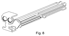
FIG. 8 is a perspective view of an alternate embodiment of the card slot divider;
FIGS. 9A–9D are block diagrams of different Network Module slot configurations;
FIGS. 10A and B are perspective views of a Network Module slot divider;
FIGS. 11A and B are perspective views of the insertion of a Network Module slot divider into a Network Module;
FIGS. 12A and B are perspective views of a Network Module slot adaptor;
FIG. 13 is a perspective view of the hardware for mounting Network Module slots and adaptors; and
FIGS. 14A and B are perspective views of Network Module adaptors inserted in various configurations in Network Module slots.
DETAILED DESCRIPTION OF THE INVENTION
Reference will now be made in detail to various embodiments of the invention. Examples of these embodiments are illustrated in the accompanying drawings. While the invention will be described in conjunction with these embodiments, it will be understood that it is not intended to limit the invention to any embodiment. On the contrary, it is intended to cover alternatives, modifications, and equivalents as may be included within the spirit and scope of the invention as defined by the appended claims. In the following description, numerous specific details are set forth in order to provide a thorough understanding of the various embodiments. However, the present invention may be practiced without some or all of these specific details. In other instances, well known process operations have not been described in detail in order not to unnecessarily obscure the present invention.
The invention will now be described with reference to various embodiments implemented in a router. In the following, the term router is utilized broadly to include any component such as a router, bridge, switch, layer 2 or layer 3 switch, gateway, etc., that is utilized to implement connectivity within a network or between networks. In the following, embodiments will be described, by way of example, not limitation, that operate on routers designed and manufactured by the assignee of the present patent application. However, it is understood by persons of skill in the art that the invention has broad utility in any router.
FIGS. 1A and B are perspective views, from two different viewpoints, of the interior of a router chassis showing parts of an embodiment of the invention and FIG. 2 is a schematic top view of the motherboard. The chassis includes a business side having slots for holding various modules. A schematic view of the business side of the chassis depicted in FIGS. 1A and B and FIG. 2 is depicted in FIG. 3.
Turning first to FIG. 1A, the “business side” of the router 10 (depicted schematically in FIG. 3) includes two card slots 2022 partitioned (as described in detail below) to hold four cards 3036 that may be Wide Area Network Interface Cards (WICs), Voice Interface Cards (VICs), Voice/Data Interface Cards (VWICs), High Speed Network Interface Cards (HWICs), or other types of interface cards.
The figure also depicts two Network Module (NM) slots 40 and 42 each configurable (as described below) to hold various combinations of Extended Double Wide Network Modules (XDWNMs), Double Wide Network Modules (DWNMs), Extended Single Wide Network Modules (XSWNMs) and/or Single Wide Network Modules (SWNMs).
As depicted in FIGS. 1A and B, the reconfigurable card slots 2022 are positioned on the a removable motherboard 60. The removable motherboard 60 has a wide section 62 on which the card slots 2022 are mounted and a narrow section 64 which passes through an opening of a vertical midplane 80. The anterior portion of the wide section 62 of the motherboard forms the upper part of the business side of the router
As will be described in more detail below, the card slots and NM slots are reconfigurable allow components with different form factors to be utilized in the same router chassis.
A first embodiment of the invention will now be describe that utilizes a field replaceable motherboard that can be removed and replaced without removing the router from the rack. FIG. 2 depicts an elevation view of the motherboard 60. The motherboard 60 has a wide external section 62 and a narrow insertion section 64. First and second MB tabs 65 and 66 on the wide external section extend beyond the narrow insertion section and each MB tab has a front edge comprising the business side of the motherboard and a rear edge. In this embodiment ejectors are used to insert the motherboard into the slot.
The system for connecting the field replaceable motherboard 60 to the mid-plane 80 will now be described with reference to FIGS. 2 and 4. As depicted in FIG. 2, first and second motherboard connectors 70 and 72 are positioned on the surface of the motherboard 60 at the rear edges of the first and second MB tabs 65 and 66.
The mid-plane board 80 has a cutaway section bounded by tabs 84 and 86. First and second mid-plane connectors 88 and 90 are positioned on the tabs 84 and 86 of the midplane so that complementary motherboard connectors positioned on the rear edges of the MB tabs 65 and 66 of the removable mother board 60 mate with the mid-plane connectors when the narrow insertion section 64 is slid between the mid-plane tabs 84 and 86.
The presently described motherboard/mid-plane configuration allows the entire motherboard to be field-replaced without removing the router from a rack unit.
Another feature of the presently described embodiment is a removable center guide that allows a card slot to be configured to hold two single wide cards or a single double wide card. FIG. 5 is a perspective view of a reconfigurable card slot 20 and a card slot divider 80, FIG. 6 depicts the insertion of the card slot divider into the card slot 20, and FIGS. 7A and B are detailed perspective views of the card slot divider 80.
Referring to FIGS. 5 and 6, the card slot 20 has a track 82 into which the card slot divider 80 is inserted. A rail on the lower part of the card slot divider slides into a track 82 located in the slot and screw hole 84 is located on the front of the slot below the track 82.
FIG. 6 is a more detailed view of the process of inserting the card slot divider 80. In this embodiment the track 82 is made of plastic and a rail 86, formed as the lower part of the slot divider, is slid into the track 82. A screw 88 is then tightened into the screw hole 84 on the slot bezel.
FIGS. 7A and B are detailed rear and front views, respectively, of the card slot divider 80. As described above, the card slot divider 80 includes a rail 86, a front tab 90 with screw, and also includes a card track 92 for guiding a card inserted into the card slot when the card slot divider 80 is installed.
An alternate embodiment of the card slot divider, depicted in FIG. 8, is a two-pronged metal slot divider that inserts into a guide. This two types of slot dividers depicted not interchangeable.
A network module slot is configurable to hold either an single Extra Double Wide Network Module (XDWNM), a single Double Wide Network Module (DWNM), or a combination of an Extra Single Wide Network Module (XSWNM) and/or a Single Wide Network Module (SWNM). This flexibility of configuration is utilized through the use of combinations of a NM slot divider and/or NM adaptor(s).
The configuration options for this embodiment are depicted schematically in FIG. 9A–D (not to scale). In FIG. 9A, an NM slot 20 with no divider or adapters holds an XDWNM. In FIG. 9B, two adapters (A) are inserted into one side of the NM slot so that the NM slot holds a DWNM. In FIG. 9C, a divider (D) is inserted into the NM slot 20 so that the NM slot holds two XSWNMs. In FIG. 9D, an adapter (A) is inserted adjacent to the right side of each XSWDM slot depicted in FIG. 9C so that the NM slot holds two SWNMs.
Network modules are in the form of boxes so the NM slots must have smooth bottom surfaces to allow insertion of network modules into the NM slots. Accordingly, a system of dividing and configuring the slots has been developed that allows the bottom surfaces of the slots to remain smooth to provide no obstructions when modules are inserted.
An embodiment of the NM slot divider will now be described with reference to FIGS. 10A and B and 11 A and B. In FIGS. 10A and B, the NM slot divider 100 is formed of an elongated body 102 including a top rail 104 and a guide for a long screw 106. Guide tabs 108 are located on the back side of the elongated body 102. The elongated body part 102 includes openings to allow cooling air circulation and clips 110 for EMI (Electromagnetic Interference) reduction.
The process for inserting the NM slot divider 100 into the NM slot 20 is depicted in FIGS. 11A and B. In FIG. 11A, the top rails 104 of the NM slot divider 100 are inserted into guide rails (not shown) located at the top of the NM slot module 20. The NM slot divider 100 is pushed into the slot and the tip of the slot divider's screw 106 and guide slots 108 fit into holes in hardware mounted at the back of the slot. When it is fully seated, the front surface of the slot divider 100 is flush with the router's rear panel. FIG. 11B depicts the configuration depicted in FIG. 9C for holding two XSWNMs.
The slot adapters will now be described with reference to FIGS. 12A and B, FIG. 13, and FIGS. 14A and B. In FIGS. 12A and B, the slot adapter 150 includes a front face 152 having a thumbscrew 154 mounted therein. The end of the slot adapter has a triangular end 156 formed thereon. The slot adapter has rectangular holes to allow for cooling air circulation and clamps 158 for EMI (Electromagnetic Interference) reduction.
FIG. 13 depicts the hardware configuration for holding the back ends of the card slot divider 100 and card slot adapter 150 stable in the NM slot. A single-capacity receptacle 160 is mounted mid-point at the rear of the slot and has an elongated section 162 for having threaded holes for accepting the tip of the long screw 106 and the the guide slots 108 of the module slot divider 100 and has a tab portiion 164 having a rectangular opening for accepting the triangular end of a slot adapter 150. A double-capacity receptacle 166 has a tab portion 168 having two rectangular openings for accepting the triangular ends of two slot adapters.
To insert a slot adapter, first the slot adapter is oriented for insertion, with the captive thumbscrew at the right side. Then, insert the slot adapter into the far right edge of the network module slot, guide the triangular end of the slot adapter into the rectangular hole at the back of the slot, and align the captive thumbscrew with the threaded hole in the chassis, slot divider, or adjacent slot adapter. The slot adapter may be fastened to the router chassis, to another slot adapter, or to a slot divider, depending on its installation location.
For example, in FIG. 14A, the first slot adapter 150 a on the right is fastened to the chassis and the second slot adapter 150 b at the left is fastened to a slot divider 100. In FIG. 14B, the first slot adapter 150 a on the far right is fastened to the chassis and the second slot adapter 150 b is fastened to the first slot adapter 150 a.
FIG. 14A depicts the configuration of FIG. 9D for SWNMs and FIG. 14B depicts the configuration of FIG. 9B for a DWNM.
The invention has now been described with reference to the preferred embodiments. Alternatives and substitutions will now be apparent to persons of skill in the art. Accordingly, it is not intended to limit the invention except as provided by the appended claims.

Claims (2)

1. A system for enabling field replacement of a component of a router without removing the router from a rack, the system comprising:
a motherboard having a narrow insertion section and a wider external section, with the wider external section having a first and second motherboard tab forming parts of the wider external section that extend beyond the narrow insertion section, with each motherboard tab having a rear edge adjacent to the narrow insertion section;
first and second motherboard connectors disposed, respectively, on the rear edges of the first and second motherboard tabs;
a midplane, disposed within the router, having a cut-out section bounded by first and second midplane tabs; and
first and second midplane connectors, mounted on the first and second midplane tabs, respectively, with the midplane tabs disposed so that the first and second motherboard connectors mate with respective first and second midplane connectors when the narrow insertion section of the motherboard is located between midplane tabs and the motherboard and the midplane are oriented substantially perpendicularly.
2. The system of claim 1 where:
said motherboard connectors include a guiding member; and
said midplane connectors include a guiding slot into which the guiding member is inserted to align the midplane connectors and motherboard connectors when the motherboard is inserted.
US11/020,733 2002-08-23 2004-12-21 Router with field replaceable motherboard Expired - Fee Related US7108559B2 (en)

Priority Applications (2)

Application Number Priority Date Filing Date Title
US11/020,733 US7108559B2 (en) 2002-08-23 2004-12-21 Router with field replaceable motherboard
US11/523,320 US7285022B2 (en) 2002-08-23 2006-09-18 Slot adapter for reconfiguring slots in a network device

Applications Claiming Priority (4)

Application Number Priority Date Filing Date Title
US10/227,472 US6796843B1 (en) 2002-08-23 2002-08-23 Connector assembly including legacy and extension parts that maintains backward compatibility
US93478804A 2004-09-03 2004-09-03
US61591104P 2004-10-04 2004-10-04
US11/020,733 US7108559B2 (en) 2002-08-23 2004-12-21 Router with field replaceable motherboard

Related Parent Applications (1)

Application Number Title Priority Date Filing Date
US93478804A Continuation-In-Part 2002-08-23 2004-09-03

Related Child Applications (1)

Application Number Title Priority Date Filing Date
US11/523,320 Division US7285022B2 (en) 2002-08-23 2006-09-18 Slot adapter for reconfiguring slots in a network device

Publications (2)

Publication Number Publication Date
US20050117282A1 US20050117282A1 (en) 2005-06-02
US7108559B2 true US7108559B2 (en) 2006-09-19

Family

ID=34623680

Family Applications (2)

Application Number Title Priority Date Filing Date
US11/020,733 Expired - Fee Related US7108559B2 (en) 2002-08-23 2004-12-21 Router with field replaceable motherboard
US11/523,320 Expired - Fee Related US7285022B2 (en) 2002-08-23 2006-09-18 Slot adapter for reconfiguring slots in a network device

Family Applications After (1)

Application Number Title Priority Date Filing Date
US11/523,320 Expired - Fee Related US7285022B2 (en) 2002-08-23 2006-09-18 Slot adapter for reconfiguring slots in a network device

Country Status (1)

Country Link
US (2) US7108559B2 (en)

Cited By (6)

* Cited by examiner, † Cited by third party
Publication number Priority date Publication date Assignee Title
US20160174294A1 (en) * 2014-12-12 2016-06-16 Hong Fu Jin Precision Industry (Wuhan) Co., Ltd. Router
US10042396B1 (en) 2017-08-17 2018-08-07 Cisco Technology, Inc. Configurable module guides for modular electronic system
US10470335B2 (en) 2017-08-17 2019-11-05 Cisco Technology, Inc. Configurable module guides for modular electronic system
US10588241B2 (en) 2018-05-11 2020-03-10 Cisco Technology, Inc. Cooling fan control in a modular electronic system during online insertion and removal
US11212937B2 (en) 2019-03-21 2021-12-28 Cisco Technology, Inc. Method and system for preventing or correcting fan reverse rotation during online installation and removal
US11864337B1 (en) * 2023-07-20 2024-01-02 Pioneer Square Brands, Inc. Hub device for portable electronic device

Families Citing this family (5)

* Cited by examiner, † Cited by third party
Publication number Priority date Publication date Assignee Title
EP1845765B1 (en) * 2006-04-11 2010-01-20 Schroff GmbH Rack
US8649180B2 (en) * 2006-05-30 2014-02-11 Hewlett-Packard Development Company, L.P. System and method for tool-less mounting of a bezel with an electronic device
US8687350B2 (en) * 2011-05-11 2014-04-01 Ez-Tech Corp Motherboard and case with hidden internal connectors
US9639497B2 (en) 2014-11-05 2017-05-02 International Business Machines Corporation Physical layer network interface module (PHY-NIM) adaptation system
CN108768677A (en) * 2018-05-02 2018-11-06 河南应用技术职业学院 A kind of data broadcast communication system for computer network based on Android platform

Citations (11)

* Cited by examiner, † Cited by third party
Publication number Priority date Publication date Assignee Title
US4677527A (en) * 1984-07-09 1987-06-30 International Business Machines Corp. Compact electrical connection and distribution system for pluggable modular devices
US5184961A (en) * 1991-06-20 1993-02-09 Burndy Corporation Modular connector frame
US5492481A (en) * 1993-02-22 1996-02-20 Augat Inc. Circuit card interface system
US5509826A (en) * 1993-10-22 1996-04-23 Burndy Corporation Very low profile card edge connector
US5549480A (en) * 1994-05-17 1996-08-27 Tongrand Limited Unitary connector allowing laterally variant positions of mating contacts of complementary connector
US5816827A (en) * 1994-05-16 1998-10-06 Intel Corporation Performance of add in printed circuit cards for computer systems
US6000953A (en) * 1997-04-11 1999-12-14 Framatome Connectors International Input/output connector for portable device and process for mounting said connector
US6058025A (en) * 1998-04-21 2000-05-02 International Business Machines Corporation Computer tailgate having expansion slot alignment pins
US6068500A (en) * 1998-07-28 2000-05-30 Itt Manufacturing Enterprises, Inc. Multi-contact PC card and host system
US6483709B1 (en) * 2000-04-28 2002-11-19 Dell Products L.P. Cable management solution for rack mounted computing components
US6590153B1 (en) * 2002-03-25 2003-07-08 Adc Dsl Systems, Inc. Electronic circuit cards

Family Cites Families (7)

* Cited by examiner, † Cited by third party
Publication number Priority date Publication date Assignee Title
US2731609A (en) * 1954-09-29 1956-01-17 Rca Corp Sliding connector for printed circuit boards
US3333156A (en) * 1965-12-01 1967-07-25 Birtcher Corp Modular printed circuit board rack with improved card guide
US5750973A (en) * 1996-10-31 1998-05-12 The Whitaker Corporation Card reader
US6359788B1 (en) * 1998-07-02 2002-03-19 Ap Labs Circuit board card cage with one-piece, integral card guide units
US6824312B2 (en) * 2001-06-04 2004-11-30 Adc Telecommunications, Inc. Telecommunications chassis and module
US6716035B2 (en) * 2002-06-07 2004-04-06 Adtron Corporation Mating assembly for an OEM device
US20050124180A1 (en) * 2003-12-09 2005-06-09 Lambert Simonovich Removable card guidance block

Patent Citations (12)

* Cited by examiner, † Cited by third party
Publication number Priority date Publication date Assignee Title
US4677527A (en) * 1984-07-09 1987-06-30 International Business Machines Corp. Compact electrical connection and distribution system for pluggable modular devices
US5184961A (en) * 1991-06-20 1993-02-09 Burndy Corporation Modular connector frame
US5492481A (en) * 1993-02-22 1996-02-20 Augat Inc. Circuit card interface system
US5509826A (en) * 1993-10-22 1996-04-23 Burndy Corporation Very low profile card edge connector
US5509826B1 (en) * 1993-10-22 1998-03-10 Burndy Corp Very low profile card edge connector
US5816827A (en) * 1994-05-16 1998-10-06 Intel Corporation Performance of add in printed circuit cards for computer systems
US5549480A (en) * 1994-05-17 1996-08-27 Tongrand Limited Unitary connector allowing laterally variant positions of mating contacts of complementary connector
US6000953A (en) * 1997-04-11 1999-12-14 Framatome Connectors International Input/output connector for portable device and process for mounting said connector
US6058025A (en) * 1998-04-21 2000-05-02 International Business Machines Corporation Computer tailgate having expansion slot alignment pins
US6068500A (en) * 1998-07-28 2000-05-30 Itt Manufacturing Enterprises, Inc. Multi-contact PC card and host system
US6483709B1 (en) * 2000-04-28 2002-11-19 Dell Products L.P. Cable management solution for rack mounted computing components
US6590153B1 (en) * 2002-03-25 2003-07-08 Adc Dsl Systems, Inc. Electronic circuit cards

Cited By (7)

* Cited by examiner, † Cited by third party
Publication number Priority date Publication date Assignee Title
US20160174294A1 (en) * 2014-12-12 2016-06-16 Hong Fu Jin Precision Industry (Wuhan) Co., Ltd. Router
US9585270B2 (en) * 2014-12-12 2017-02-28 Hong Fu Jin Precision Industry (Wuhan) Co., Ltd. Router
US10042396B1 (en) 2017-08-17 2018-08-07 Cisco Technology, Inc. Configurable module guides for modular electronic system
US10470335B2 (en) 2017-08-17 2019-11-05 Cisco Technology, Inc. Configurable module guides for modular electronic system
US10588241B2 (en) 2018-05-11 2020-03-10 Cisco Technology, Inc. Cooling fan control in a modular electronic system during online insertion and removal
US11212937B2 (en) 2019-03-21 2021-12-28 Cisco Technology, Inc. Method and system for preventing or correcting fan reverse rotation during online installation and removal
US11864337B1 (en) * 2023-07-20 2024-01-02 Pioneer Square Brands, Inc. Hub device for portable electronic device

Also Published As

Publication number Publication date
US20050117282A1 (en) 2005-06-02
US20070014093A1 (en) 2007-01-18
US7285022B2 (en) 2007-10-23

Similar Documents

Publication Publication Date Title
US7285022B2 (en) Slot adapter for reconfiguring slots in a network device
US6927974B2 (en) Simplified power and data connector for use with chassis system that houses multiple processors
EP2156718B1 (en) Backplane to mate boards with different widths
US6659292B2 (en) Rack mountable systems
US8068340B1 (en) Power supply with reversible airflow design
US6646890B1 (en) Mounting of mezzanine circuit boards to a base board
KR20070120149A (en) Advanced mezzanine card adapter
US20030022552A1 (en) Angled patch panel with cable support bar for network cable racks
US20130063894A1 (en) Server
CN110998481B (en) Configurable module guide for a modular electronic system
GB2381128A (en) Adaptor for mounting smaller circuit cards in a card cage
EP1898578A1 (en) A electric device cabinet and network switching device
KR101911500B1 (en) Electronic interconnect method and apparatus
US8054619B1 (en) Partial-slot card guide installation tool
CN213843622U (en) Rack-type beam split optical path device
EP1535365B1 (en) Improved connector assembly that maintains backward compatibility
US11212933B2 (en) Universal carrier for OCP modules
CN211859104U (en) Switching subassembly and specification type subassembly thereof
SE503511C2 (en) Device for connecting a circuit board to a connection plane
US5339220A (en) Host structure for adaptors for terminals belonging to a distributed data processing architecture
KR102054323B1 (en) Web sever having solid state disk
US5761459A (en) Mechanism for a communications network
CN218724255U (en) Detachable general formula testing arrangement
CN211127859U (en) Mobile phone mainboard case
KR20040085876A (en) Concentrated server

Legal Events

Date Code Title Description
AS Assignment

Owner name: CISCO TECHNOLOGY, INC., CALIFORNIA

Free format text: ASSIGNMENT OF ASSIGNORS INTEREST;ASSIGNORS:SHTARGOT, HELEN;MATTUR, DATTATRI;BENDER, SHAWN;AND OTHERS;REEL/FRAME:016158/0902;SIGNING DATES FROM 20041117 TO 20041129

AS Assignment

Owner name: CISCO TECHNOLOGY, INC., CALIFORNIA

Free format text: ASSIGNMENT OF ASSIGNORS INTEREST;ASSIGNOR:CRUSE, TERRI;REEL/FRAME:016908/0765

Effective date: 20050510

FPAY Fee payment

Year of fee payment: 4

FPAY Fee payment

Year of fee payment: 8

FEPP Fee payment procedure

Free format text: MAINTENANCE FEE REMINDER MAILED (ORIGINAL EVENT CODE: REM.)

LAPS Lapse for failure to pay maintenance fees

Free format text: PATENT EXPIRED FOR FAILURE TO PAY MAINTENANCE FEES (ORIGINAL EVENT CODE: EXP.); ENTITY STATUS OF PATENT OWNER: LARGE ENTITY

STCH Information on status: patent discontinuation

Free format text: PATENT EXPIRED DUE TO NONPAYMENT OF MAINTENANCE FEES UNDER 37 CFR 1.362

FP Lapsed due to failure to pay maintenance fee

Effective date: 20180919