US7131978B2 - Surgical suturing instrument and method of use - Google Patents
Surgical suturing instrument and method of use Download PDFInfo
- Publication number
- US7131978B2 US7131978B2 US10/441,652 US44165203A US7131978B2 US 7131978 B2 US7131978 B2 US 7131978B2 US 44165203 A US44165203 A US 44165203A US 7131978 B2 US7131978 B2 US 7131978B2
- Authority
- US
- United States
- Prior art keywords
- shaft
- jaws
- suture
- wire
- distal end
- Prior art date
- Legal status (The legal status is an assumption and is not a legal conclusion. Google has not performed a legal analysis and makes no representation as to the accuracy of the status listed.)
- Expired - Lifetime, expires
Links
- 0 CC1C(*(C=C)=C)=CCC1 Chemical compound CC1C(*(C=C)=C)=CCC1 0.000 description 1
Images


Classifications
-
- A—HUMAN NECESSITIES
- A61—MEDICAL OR VETERINARY SCIENCE; HYGIENE
- A61B—DIAGNOSIS; SURGERY; IDENTIFICATION
- A61B17/00—Surgical instruments, devices or methods, e.g. tourniquets
- A61B17/064—Surgical staples, i.e. penetrating the tissue
- A61B17/0644—Surgical staples, i.e. penetrating the tissue penetrating the tissue, deformable to closed position
-
- A—HUMAN NECESSITIES
- A61—MEDICAL OR VETERINARY SCIENCE; HYGIENE
- A61B—DIAGNOSIS; SURGERY; IDENTIFICATION
- A61B17/00—Surgical instruments, devices or methods, e.g. tourniquets
- A61B17/04—Surgical instruments, devices or methods, e.g. tourniquets for suturing wounds; Holders or packages for needles or suture materials
- A61B17/0469—Suturing instruments for use in minimally invasive surgery, e.g. endoscopic surgery
-
- A—HUMAN NECESSITIES
- A61—MEDICAL OR VETERINARY SCIENCE; HYGIENE
- A61B—DIAGNOSIS; SURGERY; IDENTIFICATION
- A61B17/00—Surgical instruments, devices or methods, e.g. tourniquets
- A61B17/04—Surgical instruments, devices or methods, e.g. tourniquets for suturing wounds; Holders or packages for needles or suture materials
- A61B17/0483—Hand-held instruments for holding sutures
-
- A—HUMAN NECESSITIES
- A61—MEDICAL OR VETERINARY SCIENCE; HYGIENE
- A61B—DIAGNOSIS; SURGERY; IDENTIFICATION
- A61B17/00—Surgical instruments, devices or methods, e.g. tourniquets
- A61B17/064—Surgical staples, i.e. penetrating the tissue
-
- A—HUMAN NECESSITIES
- A61—MEDICAL OR VETERINARY SCIENCE; HYGIENE
- A61B—DIAGNOSIS; SURGERY; IDENTIFICATION
- A61B17/00—Surgical instruments, devices or methods, e.g. tourniquets
- A61B17/068—Surgical staplers, e.g. containing multiple staples or clamps
-
- A—HUMAN NECESSITIES
- A61—MEDICAL OR VETERINARY SCIENCE; HYGIENE
- A61B—DIAGNOSIS; SURGERY; IDENTIFICATION
- A61B17/00—Surgical instruments, devices or methods, e.g. tourniquets
- A61B17/28—Surgical forceps
- A61B17/29—Forceps for use in minimally invasive surgery
- A61B17/2909—Handles
-
- A—HUMAN NECESSITIES
- A61—MEDICAL OR VETERINARY SCIENCE; HYGIENE
- A61B—DIAGNOSIS; SURGERY; IDENTIFICATION
- A61B17/00—Surgical instruments, devices or methods, e.g. tourniquets
- A61B2017/00004—(bio)absorbable, (bio)resorbable, resorptive
-
- A—HUMAN NECESSITIES
- A61—MEDICAL OR VETERINARY SCIENCE; HYGIENE
- A61B—DIAGNOSIS; SURGERY; IDENTIFICATION
- A61B17/00—Surgical instruments, devices or methods, e.g. tourniquets
- A61B2017/00743—Type of operation; Specification of treatment sites
- A61B2017/00778—Operations on blood vessels
- A61B2017/00783—Valvuloplasty
-
- A—HUMAN NECESSITIES
- A61—MEDICAL OR VETERINARY SCIENCE; HYGIENE
- A61B—DIAGNOSIS; SURGERY; IDENTIFICATION
- A61B17/00—Surgical instruments, devices or methods, e.g. tourniquets
- A61B2017/00743—Type of operation; Specification of treatment sites
- A61B2017/00818—Treatment of the gastro-intestinal system
- A61B2017/00827—Treatment of gastro-esophageal reflux
-
- A—HUMAN NECESSITIES
- A61—MEDICAL OR VETERINARY SCIENCE; HYGIENE
- A61B—DIAGNOSIS; SURGERY; IDENTIFICATION
- A61B17/00—Surgical instruments, devices or methods, e.g. tourniquets
- A61B17/04—Surgical instruments, devices or methods, e.g. tourniquets for suturing wounds; Holders or packages for needles or suture materials
- A61B17/06—Needles ; Sutures; Needle-suture combinations; Holders or packages for needles or suture materials
- A61B17/06166—Sutures
- A61B2017/06171—Sutures helically or spirally coiled
-
- A—HUMAN NECESSITIES
- A61—MEDICAL OR VETERINARY SCIENCE; HYGIENE
- A61B—DIAGNOSIS; SURGERY; IDENTIFICATION
- A61B17/00—Surgical instruments, devices or methods, e.g. tourniquets
- A61B17/064—Surgical staples, i.e. penetrating the tissue
- A61B2017/0646—Surgical staples, i.e. penetrating the tissue for insertion into cartillege, e.g. meniscus
-
- A—HUMAN NECESSITIES
- A61—MEDICAL OR VETERINARY SCIENCE; HYGIENE
- A61B—DIAGNOSIS; SURGERY; IDENTIFICATION
- A61B17/00—Surgical instruments, devices or methods, e.g. tourniquets
- A61B17/28—Surgical forceps
- A61B17/29—Forceps for use in minimally invasive surgery
- A61B2017/2926—Details of heads or jaws
- A61B2017/2927—Details of heads or jaws the angular position of the head being adjustable with respect to the shaft
- A61B2017/2929—Details of heads or jaws the angular position of the head being adjustable with respect to the shaft with a head rotatable about the longitudinal axis of the shaft
-
- A—HUMAN NECESSITIES
- A61—MEDICAL OR VETERINARY SCIENCE; HYGIENE
- A61F—FILTERS IMPLANTABLE INTO BLOOD VESSELS; PROSTHESES; DEVICES PROVIDING PATENCY TO, OR PREVENTING COLLAPSING OF, TUBULAR STRUCTURES OF THE BODY, e.g. STENTS; ORTHOPAEDIC, NURSING OR CONTRACEPTIVE DEVICES; FOMENTATION; TREATMENT OR PROTECTION OF EYES OR EARS; BANDAGES, DRESSINGS OR ABSORBENT PADS; FIRST-AID KITS
- A61F2/00—Filters implantable into blood vessels; Prostheses, i.e. artificial substitutes or replacements for parts of the body; Appliances for connecting them with the body; Devices providing patency to, or preventing collapsing of, tubular structures of the body, e.g. stents
- A61F2/0063—Implantable repair or support meshes, e.g. hernia meshes
Definitions
- This invention relates to medical instruments and procedures in general, and more particularly to suturing instruments and methods for suturing.
- Suturing instruments are typically used to draw together two or more portions of a subject patient (e.g., tissue such as muscle or skin) or to attach an object to the patient (e.g., to attach a piece of surgical mesh to the abdominal wall of the patient during hernia repair surgery).
- a subject patient e.g., tissue such as muscle or skin
- an object to the patient e.g., to attach a piece of surgical mesh to the abdominal wall of the patient during hernia repair surgery.
- Certain suturing instruments employ a needle that precedes a length of suture material through a subject.
- U.S. Pat. Nos. 3,470,875; 4,027,608; 4,747,358; 5,308,353; 5,674,230; 5,690,653; 5,759,188; and 5,766,186 generally disclose suturing instruments in which a needle, with trailing suture material, is passed through a subject.
- U.S. Pat. Nos. 4,890,615; 4,935,027; 5,417,700; and 5,728,112 generally disclose suturing instruments in which suture material is passed through the end of a hollow needle after that needle has passed through a subject.
- a needle must be passed through the subject in order to deploy the suture. This is generally undesirable, since the needle typically leaves a larger hole in the subject than is necessary to accommodate only the suture material. In this respect it should be appreciated that it is generally desirable to alter each portion of the material being sutured as little as possible.
- a suturing instrument has been devised which permits the suture material itself to pierce the subject without the use of a needle.
- this device does not permit sufficient flexibility with regard to the amount of tension that may be applied to the suture and tissue.
- U.S. Pat. No. 5,499,990 discloses a suturing instrument in which a 0.25 mm stainless steel suturing wire is advanced to the distal end of a suturing instrument, whereupon the distal end of the suturing wire is caused to travel in a spiral direction so as to effect stitches joining together two portions of a subject.
- the beginning and end portions of the suture may be bent toward the tissue in order to inhibit retraction of the suture wire into the tissue upon removal of the suturing instrument.
- the stainless steel wire is sufficiently firm to hold this locking set.
- the radius of the deployed suture spiral may then be decreased by advancing an outer tube over a portion of the distal end of the instrument. Again, the stainless steel wire is sufficiently firm to hold this reducing set.
- a suturing instrument approximate the portions of the material which is to be joined in the correct physiological relationship, and to urge the portions together with an appropriate amount of force. If too much force (or tension) is applied to the suture material, then the subject portions may become necrotic or the sutures may cut through the subject. If too little tension is applied to the suture material, then the healing process may be impaired.
- U.S. Pat. No. 4,453,661 discloses a surgical instrument for applying staples.
- the staples are formed from the distal end of a length of wire.
- the distal end of the wire is passed through a subject, and thereafter contacts a die that causes the wire to bend, thereby forming the staple.
- the wire is sufficiently firm to take the set imposed by the die.
- the staple portion is then cut from the wire by a knife.
- such a system suffers from the fact that it does not permit sufficient flexibility in all situations with regard to the appropriate tension to be applied to the subject, since the attachment is made by a staple which has a predefined geometry and is formed with relatively firm wire.
- the system is limited as to the type of fastening which may be applied, since the surgical instrument is limited to only applying wire staples.
- the invention provides a device for introducing a flexible elongated element through a subject.
- the device includes a proximal end and a distal end, as well as an advancement unit for longitudinally advancing the flexible elongated element toward the distal end of the device such that a distal end of the flexible elongated element may pass from the distal end of the device with sufficient force to pass through the subject.
- the device also includes a securing unit for variably adjusting a securing force applied by the flexible elongated element so as to provide the desired securement to the subject.
- the device includes a guide tube for guiding the flexible elongated element through the device, toward the distal end of the device, as well as a rotation unit for rotating the distal end of the device so as to cause the flexible elongated element to wrap around itself, whereby to adjustably apply the securing force to the flexible elongated element.
- a suturing device comprising: a housing; a shaft extending distally from said housing, at least a portion of said shaft being flexible; a pair of opposing jaws located at a distal end of said shaft; a suture drive mechanism located in said housing and adapted to advance suture material through said shaft, through one of said jaws, through a subject to be sutured, and into the other jaw; and a jaw rotation mechanism located in said housing and adapted to rotate said jaws so as to secure the suture material to the subject.
- a suturing device comprising: a housing; a shaft extending distally from said housing; a pair of opposing jaws located at a distal end of said shaft, said opposing jaws being (i) pivotally connected to said distal end of said shaft, and (ii) pivotally connected to an inner yoke movable relative to said distal end of said shaft, whereby movement of said inner yoke in a distal direction causes said opposing jaws to open relative to one another, and movement of said inner yoke in a proximal direction causes said opposing jaws to close relative to one another; a suture drive mechanism located in said housing and adapted to advance suture material through said shaft, through one of said jaws, through a subject to be sutured, and into the other jaw; and a jaw rotation mechanism located in said housing and adapted to rotate said jaws so as to secure the suture material to the subject.
- a suturing device comprising: a housing; a shaft extending distally from said housing, at least a portion of said shaft being flexible; a pair of movable jaws pivotally connected to the distal end of said shaft in opposing relation such that said jaws can open and close relative to one another; a suture drive mechanism located in said housing and adapted to advance suture material through said shaft, through one of said jaws, through a subject to be sutured, and into the other jaw; a jaw rotation mechanism located in said housing and adapted to rotate said jaws so as to secure the suture material to the subject.
- a suturing device comprising: a housing; a shaft extending distally from said housing; a pair of opposing jaws located at a distal end of said shaft; a suture drive mechanism located in said housing and adapted to advance suture material through said shaft, through one of said jaws, through a subject to be sutured, and into the other jaw; a jaw rotation mechanism located in said housing and adapted to rotate said jaws so as to secure the suture material to the subject; and a source of suture material located in the device, said suture material comprising (i) a distal portion having properties favorable for penetrating, twisting and cutting operations, and (ii) a proximal portion having properties favorable for driving operations, said source of suture material being located in the device so that said proximal portion is engaged by said suture drive mechanism.
- a suture material comprising: a distal portion having properties favorable for penetrating, twisting and cutting operations; and a proximal portion having properties favorable for driving operations.
- a method for treating gastroesophogeal reflux disease comprising: providing a suturing device comprising: a housing; a shaft extending distally from said housing; a pair of opposing jaws located at a distal end of said shaft; a suture drive mechanism located in said housing and adapted to advance suture material through said shaft, through one of said jaws, through a subject to be sutured, and into the other jaw; and a jaw rotation mechanism located in said housing and adapted to rotate said jaws so as to secure the suture material to the subject; advancing the distal end of the suturing device into a patient's stomach so that the distal end of the suturing device is adjacent to the wall of the stomach below the lower esophageal sphincter (LES); gathering together portions of the stomach wall below the LES with the pair of opposing jaws; operating the suture drive mechanism so as to advance suture material through the gathered-together portions of the stomach wall; and operating the
- a method for effecting hemostasis comprising: providing a suturing device comprising: a housing; a shaft extending distally from said housing; a pair of opposing jaws located at a distal end of said shaft; a suture drive mechanism located in said housing and adapted to advance suture material through said shaft, through one of said jaws, through a subject to be sutured, and into the other jaw; and a jaw rotation mechanism located in said housing and adapted to rotate said jaws so as to secure the suture material to the subject; advancing the distal end of the suturing device into a patient adjacent to tissue which would benefit by effecting hemostasis; gathering together portions of the tissue which would benefit by effecting hemostasis with the pair of opposing jaws; operating the suture drive mechanism so as to advance suture material through the gathered-together portions of the tissue; and operating the jaw rotation mechanism so as to secure the tissue and thereby effect hemostasis.
- a suturing device comprising:
- a shaft extending distally from said housing, at least a portion of said shaft being flexible, and said shaft having an outer surface characterized by a plurality of peaks and a plurality of troughs, whereby to make point contact with the working lumen of an endoscope;
- a suture drive mechanism located in said housing and adapted to advance suture material through said shaft, through one of said jaws, through a subject to be sutured, and into the other jaw;
- a jaw rotation mechanism located in said housing and adapted to rotate said jaws so as to secure the suture material to the subject.
- a suturing device comprising:
- a pair of movable jaws pivotally connected to the distal end of said shaft in opposing relation such that said jaws can open and close relative to one another, said opposing jaws being operated by a jaw actuating mechanism extending through said shaft;
- a suture drive mechanism located in said housing and adapted to advance suture material through said shaft, through one of said jaws, through a subject to be sutured, and into the other jaw;
- a jaw rotation mechanism located in said housing and adapted to rotate said jaws so as to secure the suture material to the subject;
- a cutting mechanism adapted for selective movement through said one of said jaws for engagement with, and severing of, suture material extending through said one of said jaws, said cutting mechanism being operated by a cutter actuating mechanism extending through said shaft;
- said jaw actuating mechanism, said suture material and said cutter actuating mechanism are disposed substantially symmetrically within said shaft.
- a suturing device comprising:
- a suture drive mechanism located in said housing and adapted to advance suture material through said shaft, through one of said jaws, through a subject to be sutured, and into the other jaw
- said wire advancing actuator comprising a sliding cage adapted for distal and proximal movement within said handle, said sliding cage comprising a flexible finger, and further wherein (1) distal movement of said sliding cage causes said finger to bindingly engage said suture wire and drive it distally, and (2) proximal movement of said sliding cage causes said finger to disengage from binding engagement with said suture wire;
- a jaw rotation mechanism located in said housing and adapted to rotate said jaws so as to secure the suture material to the subject;
- a source of suture material located in the device.
- gastroesophogeal reflux disease comprising:
- a suturing device comprising:
- gastroesophogeal reflux disease comprising:
- a suturing device comprising:
- gastroesophogeal reflux disease comprising:
- a suturing device comprising:
- FIG. 1 is a side view of a suturing instrument formed in accordance with the present invention
- FIG. 2 is a partial side view, partially in section, of the suturing instrument shown in FIG. 1 ;
- FIG. 3 is a partial top view, partially in section, of the suturing instrument shown in FIG. 1 ;
- FIG. 4 is a schematic partial side view showing some of the internal components of the suturing instrument shown in FIG. 1 ;
- FIG. 4A is a perspective view of a drive barrel assembly incorporated in the suturing instrument shown in FIG. 1 ;
- FIG. 5 is a perspective view of a wire guide support unit incorporated in the suturing instrument shown in FIG. 1 ;
- FIG. 6 is a perspective view of the suturing instrument's wire supply cartridge, which includes the wire guide support unit shown in FIG. 5 ;
- FIG. 7 is a perspective view, partially in section, of the wire supply cartridge shown in FIG. 6 ;
- FIG. 8 is a perspective rear view of the drive barrel assembly incorporated in the suturing instrument shown in FIG. 1 , with the drive barrel assembly's release lever being shown in its closed position;
- FIG. 9 is a perspective view of the proximal (i.e., rear) end of the drive barrel assembly shown in FIG. 8 , with the release lever being shown in its open position;
- FIG. 10 is a perspective view of the proximal (i.e., rear) end of the same drive barrel assembly, with the release lever being shown in its closed position, and with the wire guide and wire guide support unit being advanced relative to the drive barrel assembly (but with the remainder of the wire supply cartridge being removed from view);
- FIG. 11 is a schematic view taken along the line 11 — 11 of FIG. 4 ;
- FIG. 12 is a side view of a shaft and an end effector portion of the suturing instrument shown in FIG. 1 ;
- FIG. 13 is a side view of the end effector portion of the suturing instrument shown in FIG. 1 ;
- FIG. 14 is a side view, partially in section, of the end effector portion shown in FIG. 13 , with the end effector portion being shown with its cutting bar in its forward (i.e., non-cutting) position;
- FIG. 15 is a side view, partially in section, of the end effector portion shown in FIG. 14 , but with the end effector portion being shown with its cutting bar in its retracted (i.e., cutting) position;
- FIG. 16 is a perspective view of the end effector portion of the suturing instrument shown in FIG. 1 ;
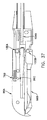
- FIGS. 17A-17J show various steps in a suturing operation conducted with the suturing instrument shown in FIG. 1 ;
- FIG. 18 is a sectional view showing one possible construction for the suturing instrument's fixed jaw portion and its associated cutting bar;
- FIG. 19 is a side view showing a piece of wire cut with the apparatus shown in FIG. 18 ;
- FIG. 20 is a sectional view showing another possible fixed construction for the suturing instrument's fixed jaw portion and its associated cutting bar;
- FIG. 21 is a side view showing a piece of wire cut with the apparatus shown in FIG. 20 ;
- FIG. 22 is a side view, partially in section, of the end effector portion of the device, wherein the end effector portion includes a piezoelectric element to aid in wire penetration;
- FIG. 23A is a schematic diagram of the device's fixed jaw portion, illustrating how the suture wire may sometimes curve as it exits the fixed jaw portion;
- FIG. 23B is a schematic diagram of a modified form of the device's fixed jaw portion, illustrating how the profile of the device can be modified so as to counteract the aforementioned wire curvature;
- FIG. 23C is a schematic diagram of a modified form of the device's movable jaw portion, illustrating how the mouth of the movable jaw portion's opening may be enlarged so as to facilitate suture capture;
- FIG. 24 is a schematic diagram of a modified form of the device, wherein one or more legs have been provided to help stabilize the tissue during suturing;
- FIG. 25 is a schematic diagram of another modified form of the device, wherein a second set of jaws have been added to the device to help stabilize the tissue during suturing;
- FIGS. 26-29 are schematic diagrams of a preferred embodiment of the present invention illustrating a novel procedure to address gastroesophogeal reflux disease (GERD);
- FIG. 29A is a schematic end view showing an alternative form of instrument shaft disposed in the working lumen of an endoscope
- FIG. 29B is a schematic end view showing another alternative form of instrument shaft disposed in the working lumen of an endoscope
- FIG. 29C is a schematic end view showing one possible way to position the shaft's working elements (i.e., the jaw linkage, wire cutting linkage and wire guide) within the instrument shaft;
- FIG. 29D is a schematic end view showing another possible way to position the shaft's working elements within the instrument shaft
- FIG. 29E shows an alternative construction for the instrument's shaft
- FIGS. 30-39 are schematic diagrams of modified forms of suturing instruments with two movable jaw portions for gripping tissue
- FIG. 40 is a schematic diagram of a supply suture wire having a softer distal wire portion optimized for tissue penetration, twisting and cutting, and a harder proximal wire portion optimized for driving;
- FIGS. 41-55 show an alternative construction for the proximal end of the suturing instrument, with FIGS. 41 and 42 showing details of the instrument's scope mount, FIGS. 43-46 showing details of the instrument's jaw actuation mechanism, FIGS. 47-53 showing details of the instrument's wire advance mechanism, and FIGS. 54 and 55 showing details of the instrument's cutting bar actuation mechanism.
- Suturing instrument 10 which comprises a preferred embodiment of the present invention.
- Suturing instrument 10 includes a housing 12 , a handle 14 , a shaft 16 and an end effector 18 .
- Suturing instrument 10 also includes a wire advance button 20 , a jaw closing actuator 22 , a wire cutting actuator 24 , a left-thumb-actuated rotation button 26 , and a right-thumb-actuated rotation button 28 (FIG. 3 ).
- Suturing instrument 10 also includes a wire supply cartridge 30 , as well as a shaft retaining nut 32 . Shaft retaining nut 32 allows shaft 16 to be dismounted from the remainder of the device for cleaning purposes.
- suture wire (comprising wire formed of metal or any other suitable material having the required flexibility and stiffness) is drawn from a winding in wire supply cartridge 30 and is pushed through housing 12 and shaft 16 to end effector 18 , which includes a pair of opposing jaw portions.
- the jaw portions may be brought together around the material which is to be sutured by actuating jaw closing actuator 22 when the jaw portions are positioned at an appropriate surgical location.
- the suture wire is driven through housing 12 and shaft 16 to end effector 18 by actuating wire advance button 20 .
- the suture wire is driven from one jaw portion to the other jaw portion with sufficient force to penetrate the tissue placed between the jaw portions, and the suture wire is permitted to pass through the second jaw portion.
- the jaw portions are then permitted to separate and move away from the tissue, leaving the suture wire extending from the subject tissue to each of the two jaw portions.
- Shaft 16 and end effector 18 (together with wire supply cartridge 30 ) may then be rotated with respect to housing 12 and handle 14 by actuating either left-thumb-actuated rotation button 26 or right-thumb-actuated rotation button 28 .
- This causes the portions of the suture wire that extend from the tissue to be twisted about one another so as to form a closed loop extending through the tissue. It will be appreciated that the size of this closed loop may be adjustably reduced by increasing the degree of twisting in the wire.
- the twisted loop of suture wire may then be cut off, at end effector 18 , from the remaining portion of the suture wire that extends back through the suturing instrument. Such cutting may be effected by actuating wire cutting actuator 24 .
- wire supply cartridge 30 may be supplied separately from suturing instrument 10 , with the wire supply cartridge 30 being loaded into suturing instrument 10 prior to commencing a suturing operation.
- wire supply cartridge 30 may be disposable, such that the cartridge may be discarded after all of its wire has been used up.
- handle 14 provides a cavity that may receive batteries 34 .
- the unit may be powered remotely via a power transmission cord or any other source of suitable power.
- Batteries 34 supply a ground (or negative) potential to a ground connector post 36 (FIG. 2 ), which in turn communicates with a rotary ground communicator 38 .
- Rotary ground communicator 38 permits electrical contact to be maintained with ground connector post 36 when rotary ground communicator 38 is rotated with respect to ground connector post 36 , as occurs when shaft 16 and end effector 18 are rotated so as to twist closed suture wire extending through the tissue.
- Batteries 34 supply a positive potential to wire advance button 20 , and to a first connector post 40 , which in turn communicates with a first rotary electrical communicator 42 .
- First rotary electrical communicator 42 permits electrical contact to be maintained with first connector post 40 when first rotary electrical communicator 42 is rotated with respect to first connector post 40 .
- the positive potential from batteries 34 is also supplied (in parallel) to each thumb-activated rotation button 26 , 28 (FIG. 3 ), and to a second connector post 44 (FIG. 2 ), which in turn communicates with a second rotary electrical communicator 46 .
- second rotary electrical communicator 46 permits electrical contact to be maintained with second connector post 44 when second rotary electrical communicator 46 is rotated with respect to second connector post 44 .
- Each of the connector posts 36 , 40 and 44 may be spring-biased so as to remain in contact with its respective rotary communicator.
- the positive potentials may be switched on by depressing the respective actuator button 20 , 26 , 28 .
- Handle 14 also includes a cap 48 which may be removed so as to permit insertion of batteries 34 .
- First rotary electrical communicator 42 is in electrical communication with a wire advance motor 50 shown in FIGS. 2 and 4 .
- the output shaft of wire advance motor 50 is coupled to a miter drive gear 52 , which is in turn coupled to a miter follower gear 54 .
- Miter follower gear 54 is coupled to a drive wheel 56 which contacts the suture wire 58 , as will be described in further detail below with reference to FIGS. 5-10 .
- Second rotary electrical communicator 46 is in electrical communication with a shaft rotation motor 60 (FIGS. 3 and 4 ), the output of which is coupled to a pinion gear 62 ( FIGS. 4 , 4 A and 11 ) that rotates along an internal gear 64 (FIGS. 4 and 11 ).
- a shaft rotation motor 60 FIGS. 3 and 4
- pinion gear 62 FIGS. 4 , 4 A and 11
- internal gear 64 FIGS. 4 and 11
- left-thumb-actuated rotation button 26 and right-thumb-activated rotation button 28 may be provided to permit the user to use the thumb of either their left hand or their right hand, respectively, so as to actuate shaft rotation motor 60 .
- shaft rotation motor 60 will rotate in the same direction regardless of which button (i.e., button 26 or button 28 ) may be actuated.
- Jaw closing actuator 22 ( FIGS. 2 and 4 ) is coupled to a jaw linkage coupler 66 , which in turn contacts a jaw linkage 68 (FIGS. 2 and 14 ).
- jaw closing actuator 22 pivots on its pivot pin 67 ( FIG. 4 ) so as to drive jaw linkage coupler 66 distally, against the force of biasing spring 69 , and so as to cause the jaw linkage 68 to move forward toward the distal end of suturing instrument 10 .
- This action will in turn cause movable jaw portion 98 to close on fixed jaw portion 96 (FIG. 17 A), as will hereinafter be discussed in further detail.
- biasing spring 69 ( FIG.
- jaw linkage coupler 66 drives jaw linkage coupler 66 proximally, so as to cause jaw linkage 68 to move proximally. This action will cause movable jaw portion 98 to open relative to fixed jaw portion 96 (FIG. 14 ), as will hereinafter be discussed in further detail.
- the action of jaw linkage 68 at the distal end of the device is discussed further below with reference to FIGS. 13 and 14 .
- Wire cutting actuator 24 is coupled to a wire cutting linkage coupler 70 (FIGS. 2 and 4 ), which in turn contacts a wire cutting linkage 72 ( FIGS. 2 , 14 and 15 ).
- wire cutting actuator 24 pivots on its pivot pin 73 ( FIG. 4 ) so as to drive wire cutting linkage coupler 70 proximally, against the force of biasing spring 69 , and so as to cause wire cutting linkage 72 to move proximally, away from the distal end of suturing instrument 10 .
- This action will in turn cause cutting bar 104 ( FIG. 14 ) to move proximally ( FIG. 15 ) so as to effect wire cutting, as will hereinafter be discussed in further detail.
- biasing spring 69 drives wire cutting linkage coupler 70 distally, so as to cause wire cutting linkage 72 to move distally. This action causes cutting bar 104 to move distally, so as to assume the position shown in FIG. 14 .
- Wire cutting linkage 72 moves adjacent to, and independent of, jaw linkage 68 discussed above. The action of wire cutting linkage 72 at the distal end of the device is discussed further below with reference to FIGS. 14 and 15 .
- the wire supply cartridge 30 shown in FIG. 1 includes a wire guide support unit 74 , as shown in FIGS. 5-7 .
- a supply coil of suture wire 58 (comprising wire formed of metal or any other suitable material having the required flexibility and stiffness) may be supplied in the base of cartridge 30 and is fed into the support unit 74 as shown in FIG. 7.
- a wire guide 76 surrounds suture wire 58 , from support unit 74 to the distal end of suturing instrument 10 , adjacent to end effector 18 ( FIGS. 5-7 , 14 and 15 ).
- Wire guide 76 ensures that suture wire 58 does not bend or buckle as the suture wire is pushed through housing 12 and shaft 16 .
- wire guide 76 preferably forms a sufficiently close sliding fit with suture wire 58 such that suture wire 58 cannot bend or buckle as the suture wire is advanced through suturing instrument 10 .
- wire guide 76 is also formed so as to present a minimum of friction to suture wire 58 as the suture wire is advanced through the instrument. The foregoing characteristics are important, inasmuch as suture wire 58 is extremely thin and flexible and highly susceptible to bending or buckling in the absence of some sort of lateral support.
- wire guide 76 might have an inside diameter of 0.008 inch and an outside diameter of 0.016 inch.
- wire guide 76 is preferably formed out of polytetrafluoroethylene (PTFE) or some other relatively lubricious material.
- PTFE polytetrafluoroethylene
- the interior of wire guide 76 may be coated with a lubricant so as to facilitate closely-supported, low-friction passage of the suture wire through the wire guide.
- suture wire 58 may comprise 316 LVM stainless steel having a tensile strength of 170 kpsi.
- wire guide 76 extends through support unit 74 (FIG. 7 ), wire guide 76 has two openings 78 (one on either side of wire guide 76 , only one of which is shown in FIG. 5 ) in the center of support unit 74 . Openings 78 expose a portion of suture wire 58 so that wire drive wheel 56 ( FIG. 8 ) may contact suture wire 58 and urge the suture wire forward toward the distal end of suturing instrument 10 , as will be discussed in detail below with reference to FIGS. 8-10 .
- housing 12 receives a drive barrel assembly 80 that contains the aforementioned motors 50 and 60 , and provides a distally-extending barrel shaft 81 (FIGS. 4 A and 8 ), on the outside of which are located the rotary communicators 38 , 42 and 46 .
- a recess 82 FIG. 4A
- a coupling pin 84 FIGS. 2 and 4
- Drive barrel assembly 80 is rotationally held within housing 12 by bearings 86 , as shown in FIGS. 2 and 3 .
- wire supply cartridge 30 may be attached to drive barrel assembly 80 by rotating a release lever 87 away from the center of drive barrel assembly 80 (FIGS. 8 and 9 ), so as to move a carriage 88 relative to drive barrel assembly 80 .
- release lever 87 rides on a pin 90
- rotation of release lever 87 from the position shown in FIG. 8 to the position shown in FIG. 9 draws carriage 88 , as well as a wire follower wheel 92 , away from the center of drive barrel assembly 80 .
- wire follower wheel 92 is separated from wire drive wheel 56 by a sufficient distance to expose the drive barrel assembly's central passageway 93 (FIG.
- wire guide 76 (overlying suture wire 58 ) may be inserted into passageway 93 (FIG. 10 ), and wire guide support unit 74 ( FIGS. 6 , 7 and 10 ) may be inserted between wheels 56 and 92 (FIG. 10 ), such that wheels 56 and 92 contact either side of suture wire 58 through openings 78 formed in either side of wire guide 76 .
- a biasing spring 94 ( FIGS. 8-10 ) is provided on carriage 88 to urge wire follower wheel 92 into close contact with suture wire 58 .
- wire follower wheel 92 may also be driven indirectly by wire drive wheel 56 in order to provide additional forces to move suture wire 58 distally (i.e., forward, toward the tool's end effector 18 ).
- Pinion gear 62 extends distally from drive barrel assembly 80 and engages the housing's internal gear 64 , as shown in FIGS. 4 and 11 .
- pinion gear 62 rotates around internal gear 64 , bringing with it the entire drive barrel assembly 80 .
- shaft 16 to rotate, since shaft 16 is coupled to drive barrel assembly 80 .
- the rotation of drive barrel assembly 80 is transferred to shaft 16 through the shaft's coupling pin 84 ( FIGS. 2 , 4 and 12 ), which is seated in recess 82 ( FIG. 8 ) of drive barrel assembly 80 .
- End effector 18 (FIGS. 1 and 13 - 16 ) includes a fixed jaw portion 96 and a movable jaw portion 98 .
- Movable jaw portion 98 is coupled to the aforementioned jaw linkage 68 ( FIG. 14 ) via a jaw linkage pin 100 , such that when jaw linkage 68 is moved distally (i.e., by pulling jaw closing actuator 22 toward handle 14 ), jaw portion 98 is rotated about a pivot pin 102 ( FIG. 13 ) and closes onto fixed jaw portion 96 .
- Wire cutting linkage 72 ( FIGS. 2 , 3 , 14 and 15 ) is coupled to a cutting bar 104 ( FIGS. 14 and 15 ) that includes a small opening 106 through which suture wire 58 may pass, as will hereinafter be discussed in further detail.
- cutting bar 104 is slidably received in a passageway 107 ( FIGS. 14 , 15 , 16 and 17 H) formed in fixed jaw portion 96 . In one position (FIG.
- cutting bar 104 is positioned in fixed jaw portion 96 such that the cutting bar's opening 106 is aligned with a channel 108 formed in fixed jaw portion 96 , whereby suture wire may be passed from the distal end of wire guide 76 , through channel 108 formed in fixed jaw portion 96 (where it undergoes an approximately 90 degree change of direction), through opening 106 in cutting bar 104 , through a channel extension 108 A formed in fixed jaw portion 96 , and across to movable jaw portion 98 , as will hereinafter be discussed in further detail.
- wire cutting linkage 72 is moved proximally by pulling wire cutting actuator 24 toward handle 14
- cutting bar 104 is also moved proximally ( FIG.
- channel extension 108 A with a length greater than channel 108 (see FIGS. 14 and 15 ) so as to prevent the suture wire from being cut in two places (i.e., at channel 108 and again at channel extension 108 A) when cutting bar 104 is moved proximally by pulling on wire cutting actuator 24 .
- the fixed jaw portion's channel 108 and channel extension 108 A, and the cutting bar's opening 106 are all sized, relative to suture wire 58 , so as to provide as much support as possible to the suture wire as it passes through, and out of, fixed jaw portion 96 .
- biasing spring 69 will normally keep cutting bar 104 in its distal position (i.e., with the cutting bar's opening 106 aligned with the fixed jaw portion's channel 108 ), unless and until wire cutting actuator 24 is activated so as to overcome the bias of spring 69 .
- release lever 87 ( FIGS. 8-10 ) may be activated so as to move wire follower wheel 92 away from, and toward, wire drive wheel 56 so as to permit a full wire supply cartridge 30 (FIGS.
- activating jaw closing actuator 22 will cause movable jaw portion 98 to close on fixed jaw portion 96 ;
- activating wire advance button 20 will cause wire drive wheel 56 to advance suture wire 58 through housing 12 and shaft 16 ;
- activating rotation button 26 and/or rotation button 28 will cause shaft 16 to rotate relative to housing 12 ; and
- activating wire cutting actuator 24 will cause cutting bar 104 to move proximally so as to sever any suture wire extending from fixed jaw portion 96 .
- Suturing instrument 10 may be used to apply wire suture 58 to a subject so as to effect a desired suturing operation.
- suturing instrument 10 may be used to suture together two portions 110 , 112 of a subject which is to be sutured.
- portions 110 , 112 might comprise two sections of severed tissue which need to be reattached to one another, or two pieces of previously unattached tissue which need to be attached to one another.
- one or the other of the portions 110 , 112 might also comprise artificial mesh or some other object being attached to tissue, etc.
- portions 110 , 112 might be located relatively deep within a patient, and might be accessed during a so-called “minimally invasive”, or a so-called “closed surgery”, procedure; however, in other circumstances, portions 110 , 112 might be accessed during a conventional, or so-called “open surgery”, procedure.
- This later situation might include procedures done at the outer surface of the patient's body, i.e., where portions 110 , 112 comprise surface subjects.
- suturing instrument 10 is initially prepared for use by installing batteries 34 into handle 14 , if batteries 34 are not already installed, and by installing wire supply cartridge 30 into the suturing instrument, if a cartridge 30 is not yet installed.
- wire supply cartridge 30 is installed in suturing instrument 10 by (1) moving the drive barrel assembly's release lever 87 to its open position (FIG. 9 ), so as to move wire follower wheel 92 away from wire drive wheel 56 and thereby expose the barrel assembly's central passageway 93 ; (2) passing the distal end of the cartridge (i.e., the distal end of wire guide 76 ) through drive barrel assembly 80 and shaft 16 until the distal end of wire guide 76 is in communication with the channel 108 formed in fixed jaw portion 96 (FIG.
- suturing instrument 10 will be ready for use, with its movable jaw portion 98 being opened away from its fixed jaw portion 96 , and with its cutting bar 104 being in its forward ( FIG. 14 ) position.
- suturing instrument 10 has its movable jaw portion 98 moved into engagement with its fixed jaw portion 96 (i.e., the jaws 96 , 98 are placed in their “closed” position) by pulling jaw closing actuator 22 toward handle 14 , and then the distal end of suturing instrument 10 is moved adjacent to subject portions 110 , 112 (FIG. 17 A).
- such positioning will generally involve moving the distal end of the suturing instrument through a cannula and into an interior body cavity; however, it is also envisioned that one might move the distal end of the suturing instrument directly into an otherwise-accessible body cavity, e.g., directly into the colon or esophagus, etc.
- such positioning might involve positioning the distal end of the suturing instrument adjacent to more readily accessible subject portions 110 , 112 .
- jaw closing actuator 22 is released, such that biasing spring 69 ( FIG. 4 ) will cause movable jaw portion 98 to open away from fixed jaw portion 96 (FIG. 17 B). Then the distal end of suturing instrument 10 is moved so that its jaws 96 , 98 straddle subject portions 110 , 112 , and then jaw closing actuator 22 is actuated again, by pulling jaw closing actuator 22 toward handle 14 , so as to close movable jaw portion 98 against fixed jaw portion 96 , whereby to capture subject portions 110 , 112 (FIG. 17 C).
- wire advance button 20 is activated so as to cause suture wire 58 to be driven forward, out of the distal end of wire guide 76 , through the fixed jaw portion's channel 108 , through opening 106 in cutting bar 104 , through the fixed jaw portion's channel extension 108 A, through subject portions 110 , 112 , and finally through an opening 113 ( FIGS. 14 , 15 and 17 C) formed in movable jaw portion 98 .
- Suture wire 58 is preferably advanced so that a length 58 A of wire 58 extends approximately 1 centimeter out of the bottom end of movable jaw portion 98 (FIG. 17 C).
- jaw closing actuator 22 is released so as to permit movable jaw portion 98 to return to its “open” position relative to fixed jaw portion 96 , and then wire advance button 20 is used to pay out additional suture wire 58 as the distal end of suturing instrument 10 is stepped back (e.g., by about a centimeter or so) from subject portions 110 , 112 (FIG. 17 D).
- jaw closing actuator 22 is used to move jaw portion 98 back into engagement with fixed jaw portion 96 once more (FIG. 17 E).
- left-thumb-actuated rotation button 26 or right-thumb-actuated rotation button 28 , is used to rotate shaft 16 and hence end effector 18 .
- This causes suture wire 58 to twist on itself, initially creating a relatively large loop 116 ( FIG. 17F ) of suture wire 58 extending from subject portions 110 , 112 toward suturing instrument 10 .
- rotation button 26 and/or rotation button 28 is used to rotate shaft 16 (and hence end effector 18 ) more and more, the loop 116 of suture material will progressively close down ( FIG. 17G ) so as to form a tight binder for subject portions 110 , 112 .
- suture wire 58 is preferably carefully selected with respect to its flexibility relative to the strength of subject portions 110 , 112 .
- suture wire 58 is chosen so as to have a flexibility such that the suture wire will twist, and loop 116 will close down, before subject portions 110 , 112 will undergo substantial deformation and/or tearing.
- 0.005 inch diameter stainless steel wire can be used with most types of mammalian tissue such that the suture wire can be twisted closed without causing substantial deformation and/or tearing of the tissue.
- suture wire 58 has been tightened to the desired degree, rotation of shaft 16 and end effector 18 is stopped, i.e., by releasing button 26 or button 28 .
- wire cutting actuator 24 is depressed (e.g., it is pulled back toward handle 14 ) so as to pull cutting bar 104 proximally and thereby sever the suture wire 58 as the suture wire emerges from the fixed jaw portion's channel 108 and enters the cutting bar's opening 106 (FIG. 17 H and FIG. 15 ).
- This action separates the deployed suture wire extending through subject portions 110 , 112 from the suture wire remaining in wire supply cartridge 30 , wire guide 76 and the fixed jaw portion's channel 108 .
- wire cutting actuator 24 is released, allowing biasing spring 69 to return cutting bar 104 to return to its distal position, and then jaw closing actuator 22 is released, allowing movable jaw portion 98 to move away from fixed jaw portion 96 .
- Suturing instrument 10 may then be removed from subject portions 110 , 112 , which action will pull wire length 58 A from movable jaw portion 98 (FIG. 17 I).
- the deployed suture wire 58 may then be pressed down flat against subject portions 110 , 112 , or rounded into a ball, or otherwise operated upon, so as to reduce the profile of, or reduce the tendency to snag on, the deployed suture wire (FIG. 17 J).
- suturing instrument 10 will have application in a broad range of different suturing operations. More particularly, it will be appreciated that suturing instrument 10 will have application in both “open” and “closed” surgical procedures, with the former including, but not limited to, large entry procedures, relatively shallow procedures, and surface procedures; and with the latter including, but not limited to, surgical procedures where access is gained to an interior structure through the use of a cannula, and surgical procedures where access is gained directly to an internal body cavity without the use of a cannula, e.g., such as a procedure conducted within the colon or the esophagus.
- suturing instrument 10 will have application where two portions of tissue must be attached to one another (e.g., where two severed pieces of tissue must be re-attached to one another, or where two separate pieces of tissue must be attached to one another, or where two sections of a single piece of tissue must be approximated to one another), and where an object must be attached to the patient (e.g., where surgical mesh must be attached to the patient's abdominal wall during hernia repair surgery, etc.).
- suturing instrument 10 will have particular application in the areas of general laparoscopic surgery, general thoracic surgery, cardiac surgery, general intestinal surgery, vascular surgery, skin surgery and plastic surgery.
- suture wire 58 will be cut with a relatively flat leading end 58 B (FIG. 19 ).
- suture wire 58 can help open the subject for the following portion of the suture wire.
- suture wire can penetrate the subject with a substantially straight path, so that the suture wire will reliably enter the movable jaw portion's opening 113 .
- suturing instrument 10 it is also possible to use suturing instrument 10 to ligate a subject rather than to pass a suture through the subject.
- suturing instrument 10 might be used to ligate a blood vessel with suture wire 58 .
- suturing instrument 10 is deployed so that suture wire 58 will pass around the far side of the subject, rather than through the subject as in the case of the suturing operation of the type described above.
- movable jaw portion 98 is first opened relative to fixed jaw portion 96 . Then suturing instrument 10 is positioned about the subject so that when movable jaw portion 98 is thereafter closed toward fixed jaw portion 96 , the fixed jaw portion's channel 108 and the movable jaw portion's opening 113 will both lie on the far side of the subject. The movable jaw portion 98 is then closed against the fixed jaw portion 96 , and suture wire 58 is passed from fixed jaw portion 96 to movable jaw portion 98 , i.e., around the far side of the subject.
- the movable jaw portion 98 is then opened, and suture wire 58 is payed out as the instrument is stepped back from the subject. Then the movable jaw portion 98 is again closed against the fixed jaw portion 96 . The shaft of the instrument is then rotated so as to form, and then close down, the ligating loop. Then cutting bar 104 is activated so as to cut the ligating loop from the remainder of the suture wire still in the tool, the movable jaw member 98 is opened, and the instrument is withdrawn from the surgical site.
- the deployed suture wire 58 may then be pressed down flat against the subject, or rounded into a ball, or otherwise operated upon, so as to reduce the profile of, or reduce the tendency to snag on, the deployed suture wire.
- fixed jaw portion 96 and movable jaw portion 98 might be formed with a greater longitudinal length so as to facilitate passing the suture wire around the far side of the subject.
- movable jaw member 98 might be formed with a recess, intermediate its jaw linkage pin 100 ( FIG. 15 ) and its opening 113 , for accommodating the subject, whereby to prevent compressing the subject when movable jaw member 98 is moved into engagement with fixed jaw member 96 .
- Suture wire 58 may comprise a wire formed out of a metal or any other suitable material having the required flexibility and stiffness.
- suture wire 58 may comprise stainless steel, titanium, tantalum, etc.
- suture wire 58 may also be coated with various active agents.
- suture wire 58 may be coated with an anti-inflammatory agent, or an anti-coagulant agent, or an antibiotic, or a radioactive agent, etc.
- FIG. 22 it is also possible to impart ultrasound energy to the wire in order to make tissue penetration easier. More particularly, because of the small cross-sectional area of the wire and the propensity for the wire to buckle when axially loaded, it is beneficial to be able to advance the wire into tissue with a minimum of load. This can be achieved by appropriately applying ultrasound energy to the wire.
- a piezoelectric element 200 is placed at the outside radius of the wire guide path 108 at the right angle bend in the fixed jaw portion 96 just before where the wire enters the tissue.
- the piezoelectric element 200 vibrates at a position along this bend such that it supports the wire in completing the turn but also imparts a component of displacement in the direction of the tissue. Displacement of this kind at ultrasonic frequencies, in addition to the existing wire driving means, would cause the tip of the wire to penetrate the tissue using less force. In addition to reducing the tendency for outright wire buckling, lowering the wire loads will also allow the wire penetration to proceed in a straighter path.
- the suture wire 58 may exit fixed jaw portion 96 with a curvature, due to the fact that suture wire 58 follows a curved channel 108 in fixed jaw portion 96 .
- this curvature in the suture wire 58 may be quite modest, so that it may be effectively ignored.
- this curvature might be large enough to cause the suture wire advancing out of fixed jaw portion 96 to miss the target opening 113 in movable jaw portion 98 .
- the curvature in suture wire 58 can present a significant problem.
- FIG. 23A it will be seen that, in some circumstances, the suture wire 58 may exit fixed jaw portion 96 with a curvature, due to the fact that suture wire 58 follows a curved channel 108 in fixed jaw portion 96 . In some cases this curvature in the suture wire 58 may be quite modest, so that it may be effectively ignored. However, in other circumstances, this curvature might be large enough to cause the suture wire advancing out of fixed jaw portion 96 to miss the
- the profile of the cutting bar's opening 106 may be modified so as to provide a deflecting die which will counteract undesirable curvature in the suture wire and return the suture wire to a straight path as the suture wire exits fixed jaw portion 96 .
- the profile of the fixed jaw portion's channel 108 may be modified, adjacent to cutting bar 104 , so as to provide a similar deflecting die which will counteract undesirable curvature in the suture wire and return the suture wire to a straight path as the suture wire exits fixed jaw portion 96 .
- the mouth of the movable jaw portion's opening 113 may be enlarged to help capture a suture wire deviating from a straight path.
- one or more legs 300 may be provided on suturing instrument 10 , wherein legs 300 help stabilize the tissue during suturing.
- a grasper 400 comprising jaws 405 and 410 , may be added to suturing instrument 10 to help stabilize the tissue during suturing.
- the end effector 18 of suturing instrument 10 may be constructed so as to have two movable, opposing jaws, rather than one fixed jaw and one movable jaw as described above.
- shaft rotation motor 60 and thumb buttons 26 , 28 may be configured so that depressing one button (e.g., button 26 ) will cause end effector 18 to rotate in one direction (e.g., clockwise), and depressing the other button (e.g., button 28 ) will cause end effector 18 to rotate in the opposite direction (e.g., counterclockwise).
- the present invention has particular application in a novel procedure to address gastroesophogeal reflux disease (GERD), among others.
- GFD gastroesophogeal reflux disease
- suturing instrument 10 may be used to gather tissue below the stomach's lower esophageal sphincter (LES) so as to improve its function and thereby reduce the symptoms of GERD.
- suturing instrument 10 is inserted into the interior of a patient's stomach so that its end effector 18 is located adjacent to the wall of the LES (FIG. 26 ), jaw portions 96 and 98 are used to gather together two spaced sections 110 , 112 of the wall of the LES (FIG. 27 ), and then suture wire 58 is used to secure together, in the manner previously described, the gathered-together portions of the stomach wall below the LES (FIGS. 28 and 29 ).
- the foregoing steps may be repeated as many times as is necessary to adequately gather the stomach wall below the patient's LES and thereby improve its function and reduce the symptoms of GERD.
- suturing instrument 10 in certain ways, or to modify suturing instrument 10 in certain ways, so as to facilitate its use in the aforementioned GERD procedure, among others.
- suturing instrument 10 is preferably formed so as to be flexible along its length. This may be accomplished by forming shaft 16 ( FIGS. 1 and 14 ) out of a flexible material, and by forming its internal components (e.g., jaw linkage 68 , wire cutting linkage 72 and wire guide 76 ) out of flexible elements.
- shaft 16 may be formed with a plastic, metal-reinforced construction, such as a construction of the sort used to form flexible endoscopes, and/or with a braided polyamide construction, etc.; jaw linkage 68 and wire cutting linkage 72 may be formed out of flexible metal rods; and wire guide 76 may be formed out of polytetrafluoroethylene (PTFE).
- PTFE polytetrafluoroethylene
- FIG. 29A there is shown a schematic outline of an alternative form of flexible shaft 16 of suturing instrument 10 .
- This embodiment of shaft 16 is characterized by a plurality of triangular apexes 16 A separated by angular recesses 16 B. Triangular apexes 16 A are arranged so that they will make point contact with the inside wall of a working lumen 16 C of an endoscope. This point contact provide significantly less contact area between the outer surface of instrument shaft 16 and the inner wall of endoscope lumen 16 C.
- FIG. 29B shows a related construction, in which shaft 16 includes a plurality of apexes 16 A separated by arcuate recesses 16 B. Again, apexes 16 A are arranged so that they will make point contact with the inside wall of a working lumen 16 C of an endoscope, whereby to generate less binding between suturing instrument 10 and the endoscope, and hence less “whipping” and better rotational control of the devices relative to one another during use.
- FIG. 29C shows, in schematic form, one possible way to dispose three working elements WE within the body of flexible shaft 16 , where the working elements WE may comprise jaw linkage 68 , wire cutting linkage 72 and wire guide 76 .
- the working elements WE may comprise jaw linkage 68 , wire cutting linkage 72 and wire guide 76 .
- the working elements WE are disposed in a relatively linear disposition, and this configuration has been found to be relatively susceptible to the aforementioned “whipping” problem if the working elements WE have different stiffnesses than the surrounding shaft material.
- the working elements WE are arranged with a more symmetrical distribution, and this latter configuration has been found to be relatively resistant to the aforementioned “whipping” problem.
- a portion of shaft 16 may be removed, e.g., at A, so as to leave a smaller, flexible spine B connecting a distal section C with a proximal section D.
- spine B may be formed integral with, and out of the same material as, distal section C and proximal section D; alternatively, spine section B may be formed out of another material, e.g., Nitinol.
- the connecting section B could be located along the center axis of shaft 16 , e.g., by making it out of a separate piece of material connected to both distal section C and proximal portion D. This latter construction can be particularly advantageous in that it can be relatively stiff in torsion as to transmit torque, yet flexible in bending along its length.
- two movable jaw portions 96 A, 98 A may be provided at the distal end of shaft 16 .
- Jaw portions 96 A, 98 A are pivotally pinned, via pivot pins 100 A and 100 B, respectively, to an outer yoke 17 A secured to the distal end of shaft 16 (FIG. 31 ).
- jaw portions 96 A, 98 A are also pivotally pinned, via a pivot pin 100 C riding in a slot 100 D, to an inner yoke 17 B (FIG. 33 ).
- Inner yoke 17 B is movably disposed within outer yoke 17 A and is secured to the end of jaw linkage 68 A.
- the mouth of the suturing instrument can be enlarged so as to facilitate gripping and drawing together tissue, e.g., such as in the aforementioned GERD procedure, and (ii) by using a single, movable inner yoke 17 B to open and close jaw portions 96 A, 98 A pinned to a fixed outer yoke 17 A, the two jaw portions can be made to reliably open and close to a corresponding and symmetrical extent, thereby ensuring uniform mouth operation at all times.
- jaw portions 96 A, 98 A are preferably provided with offset distal teeth (or fangs) 96 B, 98 B, respectively (FIG. 30 ). These teeth (or fangs) 96 B, 98 B enhance the ability of the jaw portions to grip tissue, particularly hard-to-grip tissue such as the LES during the aforementioned GERD procedure.
- jaw portions 96 A, 98 A both move, it can also be advantageous to modify certain aspects of the suturing instrument from the construction previously disclosed. More particularly, with the suturing instrument disclosed above, jaw portion 96 , which delivers suture wire 58 to the tissue, is fixed relative to shaft 16 , and wire guide 76 extends linearly into jaw portion 96 and preferably confronts a stop shoulder (FIG. 14 ). However, with the embodiment disclosed in FIGS. 30-39 , both jaw portion 96 A and jaw portion 98 A move relative to shaft 16 . As a result, with the construction of FIGS. 30-39 , it is preferred that the distal end of wire guide 76 A ( FIG.
- wire guide 76 A terminate in jaw portion 96 A in a slightly different manner so that suture wire 58 can be reliably guided into the wire guide path in jaw portion 96 A.
- wire guide 76 A be outboard of pivot pin 100 A, so that wire guide 76 A can “cut the corner” when jaw portion 96 A is in its open position (FIG. 33 ).
- the distal end of wire guide 76 A may move slightly relative to jaw portion 96 A depending on the pivotal position of jaw portion 96 A, it is preferred that the distal end of wire guide 76 A be provided with a flange 76 B ( FIG. 33 ) which is received in a slot 96 C which is formed in jaw portion 96 A, whereby wire guide 76 A can be attached to jaw portion 96 A with a floating engagement.
- cutting bar 104 and/or wire cutting linkage 72 be sized so that they can both be fully withdrawn from jaw portion 96 A when cutting bar 104 is in its withdrawn (i.e., proximal) position.
- cutting bar 104 and its associated wire cutting linkage 72 are replaced by a single cutting rod 104 A ( FIGS. 37 and 38 ) which extends from housing 12 to the end of shaft 12 .
- the distal end of cutting rod 104 A is used to selectively intrude across the wire guide path formed in jaw portion 96 A so as to sever suture wire deployed from the suturing instrument.
- Cutting rod 104 A is preferably formed out of a flexible material, such that cutting rod 104 A can extend into jaw portion 96 A even when intervening tissue should prevent full closure of jaw portion 96 A and 98 A.
- suture wire 59 A ( FIG. 40 ) of two differing characteristics: (i) a softer distal wire portion 59 B optimized for tissue penetration, twisting and cutting, and a harder proximal wire portion 59 C optimized for driving.
- distal wire portion 59 B might comprise 316L stainless steel with a tensile strength of 160 kpsi
- proximal wire portion 59 C might comprise 304 stainless steel with a tensile strength of 430 kpsi.
- Distal wire portion 59 C might be incorporated with wire supply cartridge 30 during manufacture, or distal wire portion 59 C might be added to wire supply cartridge 30 and/or suturing instrument 10 after proximal wire portion 59 C has been installed in wire supply cartridge 30 .
- Distal wire portion 59 B may or may not be secured to proximal wire portion 59 C.
- suturing instrument 10 uses the aforementioned drive barrel assembly 80 ( FIG. 8 ) to drive suture wire 58 (or suture wire 59 A)
- other apparatus may be used to drive the suture wire, e.g., a wire drive mechanism such as is disclosed in pending U.S. patent applications Ser. No. 10/051,322, filed Jan. 18, 2002 by Frederic P. Field et al. for SURGICAL SUTURING INSTRUMENT AND METHOD OF USE; or a wire drive mechanism such as is disclosed in pending U.S. patent application Ser. No. 10/039,601, filed Oct. 19, 2001 by Frederic P. Field et al.
- FIGS. 41-55 there is shown the proximal end of another suturing instrument 10 also formed in accordance with the present invention.
- the suturing instrument 10 shown in FIGS. 41-55 is particularly well suited for use in the aforementioned GERD procedure, and is substantially the same as the suturing instrument 10 described above except as will be discussed below. More particularly, the suturing instrument 10 shown in FIGS. 41-55 has a somewhat different handle assembly and controls for actuating the shaft's working elements WE (i.e., jaw linkage 68 , wire cutting linkage 72 and wire guide 76 ), and preferably uses the two movable jaw portions 96 A, 98 A shown in FIGS. 30-39 .
- WE working elements
- the suturing instrument 10 shown in FIGS. 41-55 comprises a handle 900 which carries the instrument's user controls as will hereinafter be described and from which extends shaft 16 .
- the suturing instrument 10 is intended to be used in conjunction with an endoscope, and inasmuch as it can be important to lock the longitudinal position of the suturing instrument relative to the endoscope (e.g., to permit proper viewing of the jaws through the limited depth of field typically available with the endoscope's optics), the suturing instrument preferably includes a movable scope mount 902 for selectively locking ( FIG. 42 ) and unlocking ( FIG. 41 ) the suturing instrument to the endoscope.
- suturing instrument 10 also comprises a rotation knob 904 at its proximal end for manually rotating the two movable jaw portions 96 A, 98 A to a desired orientation relative to handle 900 , and a trigger 906 for moving a trigger linkage 908 , whereby the two movable jaw portions 96 A, 98 A may be moved between an open position ( FIGS. 43 and 44 ) and a closed position (FIGS. 45 and 46 ).
- Wire drive assembly 910 comprises a push lever 912 which is connected to a sliding cage 914 .
- Sliding cage 914 includes a window 916 having a flexible finger 918 movably positioned within window 916 so as to selectively engage suture wire 58 .
- a supply of suture wire 58 is preferably wound in a recess 920 formed in sliding cage 914 .
- push lever 912 advances sliding cage 914 distally (i.e., right to left as seen in FIG. 53 ) within handle 900
- finger 918 moves into secure engagement with the suture wire 58 , whereby to advance suture wire 58 distally.
- push lever 912 retracts sliding cage 914 proximally within handle 900
- finger 918 will yield so that the finger moves out of binding engagement with the suture wire, thus imparting no motion to suture wire 58 during the sliding cage's return stroke.
- Wire drive assembly 910 also comprises a stationary cage 922 disposed in handle 900 .
- Stationary cage 922 includes a window 924 having a flexible finger 926 secured to the stationary cage 922 and extending through window 924 .
- flexible finger 926 will move distally within window 924 , so that the flexible finger 926 moves out of binding engagement with suture wire 58 , thereby allowing suture wire 58 to advance unimpeded by stationary cage 922 .
- any proximal movement of suture wire 58 will cause the stationary cage's flexible finger 926 to move into tighter engagement with suture wire 58 and prevents proximal movement of the suture wire.
- sliding cage 914 and stationary cage 922 together act as a one-way wire advancement mechanism, permitting suture wire 58 to be advanced distally within shaft 16 but preventing proximal motion.
- suturing instrument 10 also comprises a cutbar actuator 928 that is connected to wire cutting linkage 72 .
- Moving cutbar actuator 928 proximally causes cutting bar 104 to be retracted into its non-cutting position
- moving cutbar actuator 928 distally causes cutting bar 104 to move distally to its wire cutting position.
- Suturing instrument 10 preferably operates as follows.
- suturing instrument 10 in the condition shown in FIGS. 41 and 46 and (i.e., with scope mount 902 in the open position and with trigger 906 depressed so that the two movable jaw portions 96 A, 98 A are closed), the distal end of the suturing instrument is advanced into the working lumen of the endoscope. Then the suturing instrument's scope mount 902 is moved to its locked position so as to lock the suturing instrument in proper position ( FIG. 42 ) relative to the endoscope. Then the endoscope and suturing instrument are manipulated until the two movable jaw portions 96 A, 98 A are placed adjacent to the tissue which is to be sutured.
- the two jaw portions 96 A, 98 A are then opened, and suture wire 58 is payed out as the instrument is stepped back from the subject. Then the movable jaw portions 96 A, 98 A are closed again. The shaft of the instrument is then rotated using rotation knob 904 so as to form, and then close down, the tightening loop. Then cutting bar 104 is activated using cutbar actuator 928 so as to cut the tightening loop from the remainder of the suture wire still in the tool, the two jaw members 98 are opened, and the instrument is withdrawn from the surgical site.
- the deployed suture wire 58 may then be pressed down flat against the subject, or rounded into a ball, or otherwise operated upon, so as to reduce the profile of, or reduce the tendency to snag on, the deployed suture wire.
Abstract
Description
-
- a housing;
- a shaft extending distally from said housing, at least a portion of said shaft being flexible, and said shaft having an outer surface characterized by a plurality of peaks and a plurality of troughs, whereby to make point contact with the working lumen of an endoscope;
- a pair of opposing jaws located at a distal end of said shaft;
- a suture drive mechanism located in said housing and adapted to advance suture material through said shaft, through one of said jaws, through a subject to be sutured, and into the other jaw; and
- a jaw rotation mechanism located in said housing and adapted to rotate said jaws so as to secure the suture material to the subject;
-
- a housing;
- a shaft extending distally from said housing;
- a pair of opposing jaws located at a distal end of said shaft, said opposing jaws being operated by a jaw actuating mechanism extending through said shaft;
- a suture drive mechanism located in said housing and adapted to advance suture material through said shaft, through one of said jaws, through a subject to be sutured, and into the other jaw; and
- a jaw rotation mechanism located in said housing and adapted to rotate said jaws so as to secure the suture material to the subject; and
- a cutting mechanism adapted for selective movement through said one of said jaws for engagement with, and severing of, suture material extending through said one of said jaws, said cutting mechanism being operated by a cutter actuating mechanism extending through said shaft; and
- further wherein said jaw actuating mechanism, said suture material and said cutter actuating mechanism are disposed substantially symmetrically within said shaft;
-
- a housing;
- a shaft extending distally from said housing, at least a portion of said shaft being flexible;
- a pair of opposing jaws located at a distal end of said shaft;
- a suture drive mechanism located in said housing and adapted to advance suture material through said shaft, through one of said jaws, through a subject to be sutured, and into the other jaw, said wire advancing actuator comprising a sliding cage adapted for distal and proximal movement within said handle, said sliding cage comprising a flexible finger, and further wherein (1) distal movement of said sliding cage causes said finger to bindingly engage said suture wire and drive it distally, and (2) proximal movement of said sliding cage causes said finger to disengage from binding engagement with said suture wire; and
- a jaw rotation mechanism located in said housing and adapted to rotate said jaws so as to secure the suture material to the subject;
Claims (28)
Priority Applications (1)
| Application Number | Priority Date | Filing Date | Title |
|---|---|---|---|
| US10/441,652 US7131978B2 (en) | 2001-12-11 | 2003-05-19 | Surgical suturing instrument and method of use |
Applications Claiming Priority (4)
| Application Number | Priority Date | Filing Date | Title |
|---|---|---|---|
| US10/014,991 US20020128666A1 (en) | 1998-08-27 | 2001-12-11 | Surgical suturing instrument and method of use |
| US38160102P | 2002-05-17 | 2002-05-17 | |
| US10/243,556 US7037315B2 (en) | 2001-09-14 | 2002-09-13 | Surgical suturing instrument and method of use |
| US10/441,652 US7131978B2 (en) | 2001-12-11 | 2003-05-19 | Surgical suturing instrument and method of use |
Related Parent Applications (2)
| Application Number | Title | Priority Date | Filing Date |
|---|---|---|---|
| US10/014,991 Continuation-In-Part US20020128666A1 (en) | 1998-08-27 | 2001-12-11 | Surgical suturing instrument and method of use |
| US10/243,556 Continuation-In-Part US7037315B2 (en) | 2001-09-14 | 2002-09-13 | Surgical suturing instrument and method of use |
Publications (2)
| Publication Number | Publication Date |
|---|---|
| US20040092967A1 US20040092967A1 (en) | 2004-05-13 |
| US7131978B2 true US7131978B2 (en) | 2006-11-07 |
Family
ID=29552903
Family Applications (1)
| Application Number | Title | Priority Date | Filing Date |
|---|---|---|---|
| US10/441,652 Expired - Lifetime US7131978B2 (en) | 2001-12-11 | 2003-05-19 | Surgical suturing instrument and method of use |
Country Status (6)
| Country | Link |
|---|---|
| US (1) | US7131978B2 (en) |
| EP (1) | EP1505911A4 (en) |
| JP (1) | JP2005525862A (en) |
| AU (1) | AU2003241521A1 (en) |
| CA (1) | CA2484865A1 (en) |
| WO (1) | WO2003096885A2 (en) |
Cited By (95)
| Publication number | Priority date | Publication date | Assignee | Title |
|---|---|---|---|---|
| US20030181924A1 (en) * | 2002-01-30 | 2003-09-25 | Olympus Optical Co., Ltd. | Endoscopic suturing system |
| US20060157067A1 (en) * | 2005-01-14 | 2006-07-20 | Usgi Medical Inc. | Attenuation of environmental parameters on a gastric lumen |
| US20080091072A1 (en) * | 2006-10-13 | 2008-04-17 | Terumo Kabushiki Kaisha | Manipulator |
| WO2008101092A1 (en) | 2007-02-15 | 2008-08-21 | Ethicon Endo-Surgery, Inc | Method and device for retrieving suture tags |
| US20080208246A1 (en) * | 2007-02-08 | 2008-08-28 | Steve Livneh | Modular electrosurgical adaptors and multi function active shafts for use in electrosurgical instruments |
| US7655004B2 (en) | 2007-02-15 | 2010-02-02 | Ethicon Endo-Surgery, Inc. | Electroporation ablation apparatus, system, and method |
| US7815662B2 (en) | 2007-03-08 | 2010-10-19 | Ethicon Endo-Surgery, Inc. | Surgical suture anchors and deployment device |
| US20110108605A1 (en) * | 2009-11-10 | 2011-05-12 | Sapienza Jonathan W | Locking Mechanism For Use With Loading Units |
| US8037591B2 (en) | 2009-02-02 | 2011-10-18 | Ethicon Endo-Surgery, Inc. | Surgical scissors |
| US8066166B2 (en) | 2003-04-29 | 2011-11-29 | Tyco Healthcare Group Lp | Surgical stapling device with dissecting tip |
| US8070759B2 (en) | 2008-05-30 | 2011-12-06 | Ethicon Endo-Surgery, Inc. | Surgical fastening device |
| US8075572B2 (en) | 2007-04-26 | 2011-12-13 | Ethicon Endo-Surgery, Inc. | Surgical suturing apparatus |
| US8100922B2 (en) | 2007-04-27 | 2012-01-24 | Ethicon Endo-Surgery, Inc. | Curved needle suturing tool |
| US8114119B2 (en) | 2008-09-09 | 2012-02-14 | Ethicon Endo-Surgery, Inc. | Surgical grasping device |
| US8114072B2 (en) | 2008-05-30 | 2012-02-14 | Ethicon Endo-Surgery, Inc. | Electrical ablation device |
| US8157834B2 (en) | 2008-11-25 | 2012-04-17 | Ethicon Endo-Surgery, Inc. | Rotational coupling device for surgical instrument with flexible actuators |
| US8172772B2 (en) | 2008-12-11 | 2012-05-08 | Ethicon Endo-Surgery, Inc. | Specimen retrieval device |
| US8177796B2 (en) | 2009-03-23 | 2012-05-15 | Linvatec Corporation | Suture passing apparatus and method |
| US8211125B2 (en) | 2008-08-15 | 2012-07-03 | Ethicon Endo-Surgery, Inc. | Sterile appliance delivery device for endoscopic procedures |
| US8241204B2 (en) | 2008-08-29 | 2012-08-14 | Ethicon Endo-Surgery, Inc. | Articulating end cap |
| US8252057B2 (en) | 2009-01-30 | 2012-08-28 | Ethicon Endo-Surgery, Inc. | Surgical access device |
| US8262655B2 (en) | 2007-11-21 | 2012-09-11 | Ethicon Endo-Surgery, Inc. | Bipolar forceps |
| US8262680B2 (en) | 2008-03-10 | 2012-09-11 | Ethicon Endo-Surgery, Inc. | Anastomotic device |
| US8262563B2 (en) | 2008-07-14 | 2012-09-11 | Ethicon Endo-Surgery, Inc. | Endoscopic translumenal articulatable steerable overtube |
| US8317806B2 (en) | 2008-05-30 | 2012-11-27 | Ethicon Endo-Surgery, Inc. | Endoscopic suturing tension controlling and indication devices |
| US8328061B2 (en) | 2010-02-02 | 2012-12-11 | Covidien Lp | Surgical instrument for joining tissue |
| US8337394B2 (en) | 2008-10-01 | 2012-12-25 | Ethicon Endo-Surgery, Inc. | Overtube with expandable tip |
| US8353487B2 (en) | 2009-12-17 | 2013-01-15 | Ethicon Endo-Surgery, Inc. | User interface support devices for endoscopic surgical instruments |
| US8361066B2 (en) | 2009-01-12 | 2013-01-29 | Ethicon Endo-Surgery, Inc. | Electrical ablation devices |
| US8361112B2 (en) | 2008-06-27 | 2013-01-29 | Ethicon Endo-Surgery, Inc. | Surgical suture arrangement |
| US8403926B2 (en) | 2008-06-05 | 2013-03-26 | Ethicon Endo-Surgery, Inc. | Manually articulating devices |
| US8409200B2 (en) | 2008-09-03 | 2013-04-02 | Ethicon Endo-Surgery, Inc. | Surgical grasping device |
| WO2013046115A1 (en) | 2011-09-26 | 2013-04-04 | Novolap Medical Ltd. | Surgical fastening device and method |
| US8449533B2 (en) | 2009-11-09 | 2013-05-28 | Ceterix Orthopaedics, Inc. | Devices, systems and methods for meniscus repair |
| US8465505B2 (en) | 2011-05-06 | 2013-06-18 | Ceterix Orthopaedics, Inc. | Suture passer devices and methods |
| US8480689B2 (en) | 2008-09-02 | 2013-07-09 | Ethicon Endo-Surgery, Inc. | Suturing device |
| US8480657B2 (en) | 2007-10-31 | 2013-07-09 | Ethicon Endo-Surgery, Inc. | Detachable distal overtube section and methods for forming a sealable opening in the wall of an organ |
| US8496574B2 (en) | 2009-12-17 | 2013-07-30 | Ethicon Endo-Surgery, Inc. | Selectively positionable camera for surgical guide tube assembly |
| US8500809B2 (en) | 2011-01-10 | 2013-08-06 | Ceterix Orthopaedics, Inc. | Implant and method for repair of the anterior cruciate ligament |
| US8506564B2 (en) | 2009-12-18 | 2013-08-13 | Ethicon Endo-Surgery, Inc. | Surgical instrument comprising an electrode |
| US8529563B2 (en) | 2008-08-25 | 2013-09-10 | Ethicon Endo-Surgery, Inc. | Electrical ablation devices |
| US8568410B2 (en) | 2007-08-31 | 2013-10-29 | Ethicon Endo-Surgery, Inc. | Electrical ablation surgical instruments |
| US8579897B2 (en) | 2007-11-21 | 2013-11-12 | Ethicon Endo-Surgery, Inc. | Bipolar forceps |
| US8608652B2 (en) | 2009-11-05 | 2013-12-17 | Ethicon Endo-Surgery, Inc. | Vaginal entry surgical devices, kit, system, and method |
| US8652150B2 (en) | 2008-05-30 | 2014-02-18 | Ethicon Endo-Surgery, Inc. | Multifunction surgical device |
| US8663253B2 (en) | 2007-07-03 | 2014-03-04 | Ceterix Orthopaedics, Inc. | Methods of meniscus repair |
| US8679003B2 (en) | 2008-05-30 | 2014-03-25 | Ethicon Endo-Surgery, Inc. | Surgical device and endoscope including same |
| US8702731B2 (en) | 2007-07-03 | 2014-04-22 | Ceterix Orthopaedics, Inc. | Suturing and repairing tissue using in vivo suture loading |
| US8771260B2 (en) | 2008-05-30 | 2014-07-08 | Ethicon Endo-Surgery, Inc. | Actuating and articulating surgical device |
| US8821518B2 (en) | 2007-11-05 | 2014-09-02 | Ceterix Orthopaedics, Inc. | Suture passing instrument and method |
| US8828031B2 (en) | 2009-01-12 | 2014-09-09 | Ethicon Endo-Surgery, Inc. | Apparatus for forming an anastomosis |
| US8888792B2 (en) | 2008-07-14 | 2014-11-18 | Ethicon Endo-Surgery, Inc. | Tissue apposition clip application devices and methods |
| US20140358164A1 (en) * | 2004-05-07 | 2014-12-04 | Usgi Medical, Inc. | Tissue manipulation and securement system |
| US8906035B2 (en) | 2008-06-04 | 2014-12-09 | Ethicon Endo-Surgery, Inc. | Endoscopic drop off bag |
| US8911456B2 (en) | 2007-07-03 | 2014-12-16 | Ceterix Orthopaedics, Inc. | Methods and devices for preventing tissue bridging while suturing |
| US8939897B2 (en) | 2007-10-31 | 2015-01-27 | Ethicon Endo-Surgery, Inc. | Methods for closing a gastrotomy |
| US8986199B2 (en) | 2012-02-17 | 2015-03-24 | Ethicon Endo-Surgery, Inc. | Apparatus and methods for cleaning the lens of an endoscope |
| US9005198B2 (en) | 2010-01-29 | 2015-04-14 | Ethicon Endo-Surgery, Inc. | Surgical instrument comprising an electrode |
| US9011454B2 (en) | 2009-11-09 | 2015-04-21 | Ceterix Orthopaedics, Inc. | Suture passer with radiused upper jaw |
| US9028483B2 (en) | 2009-12-18 | 2015-05-12 | Ethicon Endo-Surgery, Inc. | Surgical instrument comprising an electrode |
| US9049987B2 (en) | 2011-03-17 | 2015-06-09 | Ethicon Endo-Surgery, Inc. | Hand held surgical device for manipulating an internal magnet assembly within a patient |
| WO2015089034A1 (en) * | 2013-12-09 | 2015-06-18 | Teleflex Medical Incorporated | Sliding suture grasper |
| US9078662B2 (en) | 2012-07-03 | 2015-07-14 | Ethicon Endo-Surgery, Inc. | Endoscopic cap electrode and method for using the same |
| US9211119B2 (en) | 2007-07-03 | 2015-12-15 | Ceterix Orthopaedics, Inc. | Suture passers and methods of passing suture |
| US9226772B2 (en) | 2009-01-30 | 2016-01-05 | Ethicon Endo-Surgery, Inc. | Surgical device |
| US9233241B2 (en) | 2011-02-28 | 2016-01-12 | Ethicon Endo-Surgery, Inc. | Electrical ablation devices and methods |
| US9247935B2 (en) | 2013-09-23 | 2016-02-02 | Ceterix Orthopaedics, Inc. | Arthroscopic knot pusher and suture cutter |
| US9254169B2 (en) | 2011-02-28 | 2016-02-09 | Ethicon Endo-Surgery, Inc. | Electrical ablation devices and methods |
| US9277957B2 (en) | 2012-08-15 | 2016-03-08 | Ethicon Endo-Surgery, Inc. | Electrosurgical devices and methods |
| US9314620B2 (en) | 2011-02-28 | 2016-04-19 | Ethicon Endo-Surgery, Inc. | Electrical ablation devices and methods |
| US9314234B2 (en) | 2007-07-03 | 2016-04-19 | Ceterix Orthopaedics, Inc. | Pre-tied surgical knots for use with suture passers |
| US9427255B2 (en) | 2012-05-14 | 2016-08-30 | Ethicon Endo-Surgery, Inc. | Apparatus for introducing a steerable camera assembly into a patient |
| US9492162B2 (en) | 2013-12-16 | 2016-11-15 | Ceterix Orthopaedics, Inc. | Automatically reloading suture passer devices and methods |
| US9545290B2 (en) | 2012-07-30 | 2017-01-17 | Ethicon Endo-Surgery, Inc. | Needle probe guide |
| US9572623B2 (en) | 2012-08-02 | 2017-02-21 | Ethicon Endo-Surgery, Inc. | Reusable electrode and disposable sheath |
| US9629627B2 (en) | 2014-01-28 | 2017-04-25 | Coviden Lp | Surgical apparatus |
| US9700299B2 (en) | 2011-05-06 | 2017-07-11 | Ceterix Orthopaedics, Inc. | Suture passer devices and methods |
| US20170311967A1 (en) * | 2012-01-31 | 2017-11-02 | Boston Scientific Scimed, Inc. | Multi-functional medical device and related methods of use |
| US9848868B2 (en) | 2011-01-10 | 2017-12-26 | Ceterix Orthopaedics, Inc. | Suture methods for forming locking loops stitches |
| US9913638B2 (en) | 2011-01-10 | 2018-03-13 | Ceterix Orthopaedics, Inc. | Transosteal anchoring methods for tissue repair |
| US9931114B2 (en) | 2010-09-10 | 2018-04-03 | Pivot Medical, Inc. | Method and apparatus for passing suture through tissue |
| US9936952B2 (en) | 2014-02-03 | 2018-04-10 | Covidien Lp | Introducer assembly for a surgical fastener applying apparatus |
| US10092291B2 (en) | 2011-01-25 | 2018-10-09 | Ethicon Endo-Surgery, Inc. | Surgical instrument with selectively rigidizable features |
| US10098631B2 (en) | 2010-09-10 | 2018-10-16 | Pivot Medical, Inc. | Method and apparatus for passing suture through tissue |
| US10098527B2 (en) | 2013-02-27 | 2018-10-16 | Ethidcon Endo-Surgery, Inc. | System for performing a minimally invasive surgical procedure |
| US10226245B2 (en) | 2015-07-21 | 2019-03-12 | Ceterix Orthopaedics, Inc. | Automatically reloading suture passer devices that prevent entanglement |
| US10314649B2 (en) | 2012-08-02 | 2019-06-11 | Ethicon Endo-Surgery, Inc. | Flexible expandable electrode and method of intraluminal delivery of pulsed power |
| US10405850B2 (en) | 2010-09-10 | 2019-09-10 | Pivot Medical, Inc. | Method and apparatus for passing suture through tissue |
| US10405853B2 (en) | 2015-10-02 | 2019-09-10 | Ceterix Orthpaedics, Inc. | Knot tying accessory |
| US10441273B2 (en) | 2007-07-03 | 2019-10-15 | Ceterix Orthopaedics, Inc. | Pre-tied surgical knots for use with suture passers |
| US10470757B2 (en) | 2016-03-02 | 2019-11-12 | Stryker Corporation | Suture passing instruments and methods |
| US10524778B2 (en) | 2011-09-28 | 2020-01-07 | Ceterix Orthopaedics | Suture passers adapted for use in constrained regions |
| US10537321B2 (en) | 2014-04-08 | 2020-01-21 | Ceterix Orthopaedics, Inc. | Suture passers adapted for use in constrained regions |
| US10779882B2 (en) | 2009-10-28 | 2020-09-22 | Ethicon Endo-Surgery, Inc. | Electrical ablation devices |
| US11744575B2 (en) | 2009-11-09 | 2023-09-05 | Ceterix Orthopaedics, Inc. | Suture passer devices and methods |
Families Citing this family (84)
| Publication number | Priority date | Publication date | Assignee | Title |
|---|---|---|---|---|
| US6332889B1 (en) * | 1998-08-27 | 2001-12-25 | Onux Medical, Inc. | Surgical suturing instrument and method of use |
| US8287554B2 (en) | 1999-06-22 | 2012-10-16 | Ethicon Endo-Surgery, Inc. | Method and devices for tissue reconfiguration |
| US7846180B2 (en) | 1999-06-22 | 2010-12-07 | Ethicon Endo-Surgery, Inc. | Tissue fixation devices and methods of fixing tissue |
| US6821285B2 (en) | 1999-06-22 | 2004-11-23 | Ndo Surgical, Inc. | Tissue reconfiguration |
| US6527785B2 (en) * | 1999-08-03 | 2003-03-04 | Onux Medical, Inc. | Surgical suturing instrument and method of use |
| ITCE990004A1 (en) | 1999-10-25 | 2000-01-25 | Mario Immacolato Paternuosto | VALVE FOR BIOPSY FORCEPS IN DIGESTIVE ENDOSCOPY |
| US6679895B1 (en) * | 1999-11-05 | 2004-01-20 | Onux Medical, Inc. | Apparatus and method for placing suture wires into tissue for the approximation and tensioning of tissue |
| AU2002246923A1 (en) | 2000-10-20 | 2002-07-30 | Onux Medical, Inc. | Surgical suturing instrument and method of use |
| US7011668B2 (en) * | 2001-07-23 | 2006-03-14 | Dvl Acquistion Sub, Inc. | Surgical suturing instrument and method of use |
| JP2005502416A (en) * | 2001-09-14 | 2005-01-27 | オーナックス・メディカル・インコーポレーテッド | Surgical suture instrument and method of use |
| AU2003225985A1 (en) * | 2002-03-25 | 2003-10-13 | Onux Medical, Inc. | Surgical suturing instrument and method of use |
| EP1505912A4 (en) * | 2002-05-17 | 2011-04-20 | Dvl Acquisition Sub Inc | Surgical suturing instrument and method of use |
| US9060770B2 (en) | 2003-05-20 | 2015-06-23 | Ethicon Endo-Surgery, Inc. | Robotically-driven surgical instrument with E-beam driver |
| US20070084897A1 (en) | 2003-05-20 | 2007-04-19 | Shelton Frederick E Iv | Articulating surgical stapling instrument incorporating a two-piece e-beam firing mechanism |
| US20040260337A1 (en) | 2003-06-18 | 2004-12-23 | Scimed Life Systems, Inc. | Endoscopic instruments and methods of manufacture |
| US8469993B2 (en) | 2003-06-18 | 2013-06-25 | Boston Scientific Scimed, Inc. | Endoscopic instruments |
| US7588545B2 (en) | 2003-09-10 | 2009-09-15 | Boston Scientific Scimed, Inc. | Forceps and collection assembly with accompanying mechanisms and related methods of use |
| US7942896B2 (en) * | 2003-11-25 | 2011-05-17 | Scimed Life Systems, Inc. | Forceps and collection assembly and related methods of use and manufacture |
| US11896225B2 (en) | 2004-07-28 | 2024-02-13 | Cilag Gmbh International | Staple cartridge comprising a pan |
| US7762960B2 (en) | 2005-05-13 | 2010-07-27 | Boston Scientific Scimed, Inc. | Biopsy forceps assemblies |
| US11246590B2 (en) | 2005-08-31 | 2022-02-15 | Cilag Gmbh International | Staple cartridge including staple drivers having different unfired heights |
| US8186555B2 (en) | 2006-01-31 | 2012-05-29 | Ethicon Endo-Surgery, Inc. | Motor-driven surgical cutting and fastening instrument with mechanical closure system |
| US8708213B2 (en) | 2006-01-31 | 2014-04-29 | Ethicon Endo-Surgery, Inc. | Surgical instrument having a feedback system |
| US7845537B2 (en) | 2006-01-31 | 2010-12-07 | Ethicon Endo-Surgery, Inc. | Surgical instrument having recording capabilities |
| US8585733B2 (en) * | 2006-04-19 | 2013-11-19 | Vibrynt, Inc | Devices, tools and methods for performing minimally invasive abdominal surgical procedures |
| US7976554B2 (en) | 2006-04-19 | 2011-07-12 | Vibrynt, Inc. | Devices, tools and methods for performing minimally invasive abdominal surgical procedures |
| US20090281500A1 (en) * | 2006-04-19 | 2009-11-12 | Acosta Pablo G | Devices, system and methods for minimally invasive abdominal surgical procedures |
| US20090281563A1 (en) * | 2006-04-19 | 2009-11-12 | Newell Matthew B | Devices, tools and methods for performing minimally invasive abdominal surgical procedures |
| US8105355B2 (en) | 2006-05-18 | 2012-01-31 | C.R. Bard, Inc. | Suture lock fastening device |
| PL2061385T3 (en) | 2006-09-13 | 2015-06-30 | Vascular Insights Llc | Vascular treatment device |
| EP2083702B1 (en) | 2006-10-05 | 2019-02-13 | Covidien LP | Axial stitching device |
| US8177794B2 (en) | 2006-10-05 | 2012-05-15 | Tyco Healthcare Group Lp | Flexible endoscopic stitching devices |
| JP4747070B2 (en) * | 2006-10-13 | 2011-08-10 | テルモ株式会社 | manipulator |
| US8684253B2 (en) | 2007-01-10 | 2014-04-01 | Ethicon Endo-Surgery, Inc. | Surgical instrument with wireless communication between a control unit of a robotic system and remote sensor |
| US8852216B2 (en) | 2007-03-23 | 2014-10-07 | Ethicon Endo-Surgery, Inc. | Tissue approximation methods |
| US8931682B2 (en) | 2007-06-04 | 2015-01-13 | Ethicon Endo-Surgery, Inc. | Robotically-controlled shaft based rotary drive systems for surgical instruments |
| US11672531B2 (en) | 2007-06-04 | 2023-06-13 | Cilag Gmbh International | Rotary drive systems for surgical instruments |
| US11849941B2 (en) | 2007-06-29 | 2023-12-26 | Cilag Gmbh International | Staple cartridge having staple cavities extending at a transverse angle relative to a longitudinal cartridge axis |
| US8758342B2 (en) * | 2007-11-28 | 2014-06-24 | Covidien Ag | Cordless power-assisted medical cauterization and cutting device |
| US8864776B2 (en) * | 2008-04-11 | 2014-10-21 | Covidien Lp | Deployment system for surgical suture |
| US8628545B2 (en) * | 2008-06-13 | 2014-01-14 | Covidien Lp | Endoscopic stitching devices |
| US20110040308A1 (en) | 2008-06-13 | 2011-02-17 | Ramiro Cabrera | Endoscopic Stitching Devices |
| US9005230B2 (en) | 2008-09-23 | 2015-04-14 | Ethicon Endo-Surgery, Inc. | Motorized surgical instrument |
| USD708746S1 (en) | 2009-06-10 | 2014-07-08 | Covidien Lp | Handle for surgical device |
| US8490713B2 (en) * | 2009-10-06 | 2013-07-23 | Covidien Lp | Handle assembly for endoscopic suturing device |
| US9700317B2 (en) | 2010-09-30 | 2017-07-11 | Ethicon Endo-Surgery, Llc | Fastener cartridge comprising a releasable tissue thickness compensator |
| US10945731B2 (en) | 2010-09-30 | 2021-03-16 | Ethicon Llc | Tissue thickness compensator comprising controlled release and expansion |
| US9386988B2 (en) | 2010-09-30 | 2016-07-12 | Ethicon End-Surgery, LLC | Retainer assembly including a tissue thickness compensator |
| US9629814B2 (en) | 2010-09-30 | 2017-04-25 | Ethicon Endo-Surgery, Llc | Tissue thickness compensator configured to redistribute compressive forces |
| US11925354B2 (en) | 2010-09-30 | 2024-03-12 | Cilag Gmbh International | Staple cartridge comprising staples positioned within a compressible portion thereof |
| US9585667B2 (en) | 2010-11-15 | 2017-03-07 | Vascular Insights Llc | Sclerotherapy catheter with lumen having wire rotated by motor and simultaneous withdrawal from vein |
| US8864777B2 (en) * | 2011-01-28 | 2014-10-21 | Anchor Orthopedics Xt Inc. | Methods for facilitating tissue puncture |
| US8968340B2 (en) | 2011-02-23 | 2015-03-03 | Covidien Lp | Single actuating jaw flexible endolumenal stitching device |
| EP2741681B1 (en) * | 2011-08-14 | 2018-10-03 | Safepath Medical Inc. | Device for suturing tissue |
| US8382775B1 (en) | 2012-01-08 | 2013-02-26 | Vibrynt, Inc. | Methods, instruments and devices for extragastric reduction of stomach volume |
| US9314362B2 (en) | 2012-01-08 | 2016-04-19 | Vibrynt, Inc. | Methods, instruments and devices for extragastric reduction of stomach volume |
| JP6305979B2 (en) | 2012-03-28 | 2018-04-04 | エシコン・エンド−サージェリィ・インコーポレイテッドEthicon Endo−Surgery,Inc. | Tissue thickness compensator with multiple layers |
| EP2967550A4 (en) | 2013-03-15 | 2016-11-09 | Anchor Orthopedics Xt Inc | Apparatus and methods for loading suture |
| EP3087939A4 (en) * | 2013-12-27 | 2017-09-27 | Olympus Corporation | Treatment tool |
| CN106456176B (en) | 2014-04-16 | 2019-06-28 | 伊西康内外科有限责任公司 | Fastener cartridge including the extension with various configuration |
| JP6532889B2 (en) | 2014-04-16 | 2019-06-19 | エシコン エルエルシーEthicon LLC | Fastener cartridge assembly and staple holder cover arrangement |
| US9468434B2 (en) | 2014-06-03 | 2016-10-18 | Covidien Lp | Stitching end effector |
| US9924944B2 (en) | 2014-10-16 | 2018-03-27 | Ethicon Llc | Staple cartridge comprising an adjunct material |
| US10390825B2 (en) | 2015-03-31 | 2019-08-27 | Ethicon Llc | Surgical instrument with progressive rotary drive systems |
| US10092286B2 (en) | 2015-05-27 | 2018-10-09 | Covidien Lp | Suturing loading unit |
| US10105139B2 (en) | 2015-09-23 | 2018-10-23 | Ethicon Llc | Surgical stapler having downstream current-based motor control |
| US11890015B2 (en) | 2015-09-30 | 2024-02-06 | Cilag Gmbh International | Compressible adjunct with crossing spacer fibers |
| US10357247B2 (en) | 2016-04-15 | 2019-07-23 | Ethicon Llc | Surgical instrument with multiple program responses during a firing motion |
| US20170296173A1 (en) | 2016-04-18 | 2017-10-19 | Ethicon Endo-Surgery, Llc | Method for operating a surgical instrument |
| US10542970B2 (en) | 2016-05-31 | 2020-01-28 | Covidien Lp | Endoscopic stitching device |
| US10945723B2 (en) | 2016-11-17 | 2021-03-16 | SafePath Medical, Inc. | Systems and methods for suturing tissue |
| JP7010956B2 (en) | 2016-12-21 | 2022-01-26 | エシコン エルエルシー | How to staple tissue |
| US20180168625A1 (en) | 2016-12-21 | 2018-06-21 | Ethicon Endo-Surgery, Llc | Surgical stapling instruments with smart staple cartridges |
| US10307170B2 (en) | 2017-06-20 | 2019-06-04 | Ethicon Llc | Method for closed loop control of motor velocity of a surgical stapling and cutting instrument |
| CN109381254B (en) * | 2017-08-02 | 2024-02-13 | 上海市嘉定区安亭医院 | Needle holder with electrocoagulation function for digestive endoscopy |
| CN109381243B (en) * | 2017-08-02 | 2024-02-13 | 上海市嘉定区安亭医院 | Vascular forceps with electrocoagulation function for digestive endoscopic surgery |
| CN109381232B (en) * | 2017-08-02 | 2024-02-13 | 上海市嘉定区安亭医院 | Needle holding forceps for minimally invasive operation under digestive endoscope |
| US10779826B2 (en) | 2017-12-15 | 2020-09-22 | Ethicon Llc | Methods of operating surgical end effectors |
| US11197665B2 (en) | 2018-08-06 | 2021-12-14 | Covidien Lp | Needle reload device for use with endostitch device |
| USD1013170S1 (en) | 2020-10-29 | 2024-01-30 | Cilag Gmbh International | Surgical instrument assembly |
| US11826042B2 (en) | 2021-03-22 | 2023-11-28 | Cilag Gmbh International | Surgical instrument comprising a firing drive including a selectable leverage mechanism |
| US11806011B2 (en) | 2021-03-22 | 2023-11-07 | Cilag Gmbh International | Stapling instrument comprising tissue compression systems |
| US20220378426A1 (en) | 2021-05-28 | 2022-12-01 | Cilag Gmbh International | Stapling instrument comprising a mounted shaft orientation sensor |
| US11937816B2 (en) | 2021-10-28 | 2024-03-26 | Cilag Gmbh International | Electrical lead arrangements for surgical instruments |
Citations (106)
| Publication number | Priority date | Publication date | Assignee | Title |
|---|---|---|---|---|
| US919138A (en) | 1909-03-16 | 1909-04-20 | Clarence A Drake | Surgical needle. |
| US1449087A (en) | 1921-12-05 | 1923-03-20 | Edwin P Bugbee | Suturing instrument |
| US1815725A (en) | 1930-02-03 | 1931-07-21 | George P Pilling & Son Company | Suture forceps |
| US2579192A (en) | 1950-08-15 | 1951-12-18 | George H Sciaroni | Suturing instrument |
| US2613562A (en) | 1947-05-27 | 1952-10-14 | John W Clark | Watch hand pressing tool |
| US2897820A (en) | 1956-10-23 | 1959-08-04 | Tauber Robert | Surgical needle guiding instrument |
| US3013559A (en) | 1959-05-06 | 1961-12-19 | Wesley C Thomas | Instrument for closing flesh wounds |
| US3404677A (en) | 1965-07-08 | 1968-10-08 | Henry A. Springer | Biopsy and tissue removing device |
| US3470875A (en) | 1966-10-06 | 1969-10-07 | Alfred A Johnson | Surgical clamping and suturing instrument |
| US3545444A (en) | 1967-10-02 | 1970-12-08 | United States Surgical Corp | Wire suture wrapping instrument |
| US3584628A (en) | 1968-10-11 | 1971-06-15 | United States Surgical Corp | Wire suture wrapping instrument |
| US3675688A (en) | 1970-04-27 | 1972-07-11 | United States Surgical Corp | Instrument for ligating, suturing and dividing organic tubular structures |
| US3735762A (en) | 1970-04-27 | 1973-05-29 | Us Corp Baltimo E | Instrument for ligating suturing and dividing organic tubular structures |
| US3802438A (en) | 1972-03-31 | 1974-04-09 | Technibiotics | Surgical instrument |
| US3807407A (en) | 1971-06-07 | 1974-04-30 | E Schweizer | Suture applicator |
| US3840017A (en) | 1971-10-29 | 1974-10-08 | A Violante | Surgical instrument |
| US3841521A (en) | 1970-08-17 | 1974-10-15 | R Jarvik | Repeating ligature guns, multi-ligature cartridges and preformed ligatures therefor |
| US3842840A (en) | 1973-05-07 | 1974-10-22 | E Schweizer | Suture applicator |
| US3858783A (en) | 1972-11-20 | 1975-01-07 | Nikolai Nikolaevich Kapitanov | Surgical instrument for stitching up tissues with lengths of suture wire |
| US3877570A (en) | 1973-07-25 | 1975-04-15 | Robert J Barry | Sterile cosmetic suture for attaching hair pieces to scalp and method of packaging and utilizing |
| US3959960A (en) | 1975-03-12 | 1976-06-01 | Santos Manuel V | Tensioning, twisting and cutting device for sutures |
| USRE28932E (en) | 1972-09-29 | 1976-08-17 | United States Surgical Corporation | Surgical stapling instrument |
| US4006747A (en) | 1975-04-23 | 1977-02-08 | Ethicon, Inc. | Surgical method |
| US4027608A (en) | 1976-02-20 | 1977-06-07 | Raymond Kelder | Suturing device |
| US4091880A (en) | 1975-10-17 | 1978-05-30 | Concept Inc. | Surgical wire inserter apparatus |
| US4103690A (en) | 1977-03-21 | 1978-08-01 | Cordis Corporation | Self-suturing cardiac pacer lead |
| US4109658A (en) | 1977-02-04 | 1978-08-29 | Hughes Joe L | Needle holding device with pick-up means |
| US4161951A (en) | 1978-04-27 | 1979-07-24 | Scanlan International, Inc. | Needle driver |
| US4164225A (en) | 1977-12-28 | 1979-08-14 | Johnson & Lorenz, Inc. | Surgical suturing instrument |
| US4204541A (en) | 1977-01-24 | 1980-05-27 | Kapitanov Nikolai N | Surgical instrument for stitching up soft tissues with lengths of spiked suture material |
| US4224947A (en) | 1979-02-05 | 1980-09-30 | Mamoru Fukuda | Suturing apparatus |
| US4235238A (en) | 1978-05-11 | 1980-11-25 | Olympus Optical Co., Ltd. | Apparatus for suturing coeliac tissues |
| US4235177A (en) | 1979-02-23 | 1980-11-25 | Raymond C. Kelder | Suturing device |
| US4258716A (en) | 1978-02-06 | 1981-03-31 | The University Of Melbourne | Microsurgical instruments |
| US4306560A (en) | 1978-07-10 | 1981-12-22 | Cordis Corporation | Suture forming tool for securing an electrode to generally inaccessible body tissue |
| US4453661A (en) | 1980-10-23 | 1984-06-12 | Ivano-Frankovsky Gosudarstvenny Meditsinsky Institut | Surgical instrument for applying staples |
| US4462404A (en) | 1981-01-31 | 1984-07-31 | Vormals Jetter & Scheerer Aesculap-Werke Aktiengesellschaft | Forceps- or tweezers-shaped surgical instrument |
| US4474181A (en) | 1982-02-18 | 1984-10-02 | Schenck Robert R | Method and apparatus for anastomosing small blood vessels |
| US4527724A (en) | 1983-06-10 | 1985-07-09 | Senmed, Inc. | Disposable linear surgical stapling instrument |
| US4553543A (en) | 1984-03-05 | 1985-11-19 | Amarasinghe Disamodha C | Suturing assembly and method |
| US4557265A (en) | 1983-02-08 | 1985-12-10 | Innova Ab | Suturing instrument |
| US4583541A (en) | 1984-05-07 | 1986-04-22 | Barry Joseph P | Sternal stabilization device |
| US4595007A (en) | 1983-03-14 | 1986-06-17 | Ethicon, Inc. | Split ring type tissue fastener |
| US4602636A (en) | 1983-03-08 | 1986-07-29 | Joint Medical Products Corporation | Suture wire with integral needle-like tip |
| US4607637A (en) | 1983-07-22 | 1986-08-26 | Anders Berggren | Surgical instrument for performing anastomosis with the aid of ring-like fastening elements and the fastening elements for performing anastomosis |
| US4610383A (en) | 1983-10-14 | 1986-09-09 | Senmed, Inc. | Disposable linear surgical stapler |
| US4612933A (en) | 1984-03-30 | 1986-09-23 | Senmed, Inc. | Multiple-load cartridge assembly for a linear surgical stapling instrument |
| US4624257A (en) | 1982-06-24 | 1986-11-25 | Anders Berggren | Surgical instrument for performing anastomosis |
| US4643190A (en) | 1984-06-23 | 1987-02-17 | Richard Wolf Gmbh | Medical forceps |
| US4644651A (en) | 1984-03-19 | 1987-02-24 | Jacobsen Research Corp. | Instrument for gripping or cutting |
| US4669473A (en) | 1985-09-06 | 1987-06-02 | Acufex Microsurgical, Inc. | Surgical fastener |
| US4705040A (en) | 1985-11-18 | 1987-11-10 | Medi-Tech, Incorporated | Percutaneous fixation of hollow organs |
| US4728020A (en) | 1985-08-30 | 1988-03-01 | United States Surgical Corporation | Articulated surgical fastener applying apparatus |
| US4741330A (en) | 1983-05-19 | 1988-05-03 | Hayhurst John O | Method and apparatus for anchoring and manipulating cartilage |
| US4747358A (en) | 1986-01-30 | 1988-05-31 | G.M.Pfaff Aktiengesellschaft | Surgical suturing machine |
| US4760848A (en) | 1986-11-03 | 1988-08-02 | Hasson Harrith M | Rotational surgical instrument |
| US4763669A (en) | 1986-01-09 | 1988-08-16 | Jaeger John C | Surgical instrument with adjustable angle of operation |
| US4803984A (en) | 1987-07-06 | 1989-02-14 | Montefiore Hospital Association Of Western Pennsylvania | Method for performing small vessel anastomosis |
| US4819635A (en) | 1987-09-18 | 1989-04-11 | Henry Shapiro | Tubular microsurgery cutting apparatus |
| US4890615A (en) | 1987-11-05 | 1990-01-02 | Concept, Inc. | Arthroscopic suturing instrument |
| US4901721A (en) | 1988-08-02 | 1990-02-20 | Hakki Samir I | Suturing device |
| US4915107A (en) | 1988-03-09 | 1990-04-10 | Harley International Medical Ltd. | Automatic instrument for purse-string sutures for surgical use |
| US4919152A (en) | 1987-03-02 | 1990-04-24 | Ralph Ger | Method of closing the opening of a hernial sac |
| US4935027A (en) | 1989-08-21 | 1990-06-19 | Inbae Yoon | Surgical suture instrument with remotely controllable suture material advancement |
| US4938214A (en) | 1984-09-10 | 1990-07-03 | Micrins Surgical Instruments, Ltd. | Hand held surgical tool |
| US4941466A (en) | 1987-04-13 | 1990-07-17 | Romano Jack W | Curved bore drilling method and apparatus |
| US4955887A (en) | 1988-05-11 | 1990-09-11 | Storz Instrument Company | Optical surgical instrument |
| US4957498A (en) | 1987-11-05 | 1990-09-18 | Concept, Inc. | Suturing instrument |
| US4966600A (en) | 1989-01-26 | 1990-10-30 | Songer Robert J | Surgical securance method |
| US4997436A (en) | 1988-06-03 | 1991-03-05 | Oberlander Michael A | Arthroscopic clip insertion tool |
| US5002564A (en) | 1989-06-19 | 1991-03-26 | Ethicon, Inc. | Surgical needle configuration with spatula geometry |
| US5004469A (en) | 1989-03-07 | 1991-04-02 | Ricerche Biomediche S.R.L. | Improvements in automatic mechanical suturing guns |
| US5021059A (en) | 1990-05-07 | 1991-06-04 | Kensey Nash Corporation | Plug device with pulley for sealing punctures in tissue and methods of use |
| US5037433A (en) | 1990-05-17 | 1991-08-06 | Wilk Peter J | Endoscopic suturing device and related method and suture |
| US5100042A (en) | 1990-03-05 | 1992-03-31 | United States Surgical Corporation | Surgical fastener apparatus |
| US5133735A (en) | 1990-05-10 | 1992-07-28 | Symbiosis Corporation | Thumb-activated actuating member for imparting reciprocal motion to push rod of a disposable laparoscopic surgical instrument |
| US5147373A (en) | 1991-04-29 | 1992-09-15 | Ferzli George S | Laparoscopic instrument |
| US5161725A (en) | 1990-02-13 | 1992-11-10 | Ethicon, Inc. | Rotating head skin stapler |
| US5171256A (en) | 1990-05-10 | 1992-12-15 | Symbiosis Corporation | Single acting disposable laparoscopic scissors |
| US5174300A (en) | 1991-04-04 | 1992-12-29 | Symbiosis Corporation | Endoscopic surgical instruments having rotatable end effectors |
| US5181919A (en) | 1991-04-23 | 1993-01-26 | Arieh Bergman | Suture ligating device for use with an endoscope |
| US5189919A (en) * | 1991-04-29 | 1993-03-02 | Atlantic Richfield Company | Wellhead fluid sampler |
| US5192298A (en) | 1990-05-10 | 1993-03-09 | Symbiosis Corporation | Disposable laparoscopic surgical instruments |
| US5197971A (en) | 1990-03-02 | 1993-03-30 | Bonutti Peter M | Arthroscopic retractor and method of using the same |
| US5207697A (en) | 1991-06-27 | 1993-05-04 | Stryker Corporation | Battery powered surgical handpiece |
| US5209747A (en) | 1990-12-13 | 1993-05-11 | Knoepfler Dennis J | Adjustable angle medical forceps |
| US5211650A (en) | 1991-01-07 | 1993-05-18 | Laparomed Corporation | Dual function suturing device and method |
| US5217465A (en) | 1992-02-28 | 1993-06-08 | Alcon Surgical, Inc. | Flexible and steerable aspiration tip for microsurgery |
| US5219357A (en) | 1990-05-31 | 1993-06-15 | Tnco, Inc. | Micro-instrument |
| US5234453A (en) | 1990-05-10 | 1993-08-10 | Symblosis Corporation | Cobalt base alloy end effectors for laparoscopic surgical scissors |
| US5243443A (en) | 1991-12-06 | 1993-09-07 | Xerox Corporation | Halftoning with error feedback and image dependent enhancement |
| US5242459A (en) | 1992-07-10 | 1993-09-07 | Laparomed Corporation | Device and method for applying a ligating loop |
| US5254126A (en) | 1992-06-24 | 1993-10-19 | Ethicon, Inc. | Endoscopic suture punch |
| US5261917A (en) | 1992-02-19 | 1993-11-16 | Hasson Harrith M | Suture tying forceps with a plurality of suture holders and method of tying a suture |
| US5290284A (en) | 1992-05-01 | 1994-03-01 | Adair Edwin Lloyd | Laparoscopic surgical ligation and electrosurgical coagulation and cutting device |
| US5304183A (en) | 1992-03-23 | 1994-04-19 | Laparomed Corporation | Tethered clamp retractor |
| US5306281A (en) | 1992-08-31 | 1994-04-26 | Merrimac Industries, Inc. | Suturing cassette device |
| US5308353A (en) | 1992-08-31 | 1994-05-03 | Merrimac Industries, Inc. | Surgical suturing device |
| US6086600A (en) * | 1997-11-03 | 2000-07-11 | Symbiosis Corporation | Flexible endoscopic surgical instrument for invagination and fundoplication |
| US20010049469A1 (en) * | 1997-11-03 | 2001-12-06 | Symbiosis Corporation | Surgical instrument for invagination and fundoplication |
| US20020068949A1 (en) * | 1996-02-23 | 2002-06-06 | Williamson Warren P. | Extremely long wire fasteners for use in minimally invasive surgery and means and method for handling those fasteners |
| US20020111534A1 (en) * | 2000-07-24 | 2002-08-15 | Takayuki Suzuki | Endoscope and endoscopic instrument and method using same |
| US20020183768A1 (en) * | 2001-05-30 | 2002-12-05 | Deem Mark E. | Obesity treatment tools and methods |
| US6494888B1 (en) * | 1999-06-22 | 2002-12-17 | Ndo Surgical, Inc. | Tissue reconfiguration |
| US6554845B1 (en) * | 2000-09-15 | 2003-04-29 | PARÉ Surgical, Inc. | Suturing apparatus and method |
| US6663639B1 (en) * | 1999-06-22 | 2003-12-16 | Ndo Surgical, Inc. | Methods and devices for tissue reconfiguration |
Family Cites Families (60)
| Publication number | Priority date | Publication date | Assignee | Title |
|---|---|---|---|---|
| FR2252531B1 (en) * | 1973-11-22 | 1977-08-12 | Dupont S T | |
| US5893863A (en) * | 1989-12-05 | 1999-04-13 | Yoon; Inbae | Surgical instrument with jaws and movable internal hook member for use thereof |
| DK166600B1 (en) * | 1991-01-17 | 1993-06-21 | Therkel Bisgaard | TOOL USE TOUCH BY SUTURING IN DEEP OPERATING OPENINGS OR BODY SPACES |
| WO1993001750A1 (en) * | 1991-07-23 | 1993-02-04 | Kernforschungszentrum Karlsruhe Gmbh | Surgical stitching instrument |
| US5307976A (en) * | 1991-10-18 | 1994-05-03 | Ethicon, Inc. | Linear stapling mechanism with cutting means |
| US5417700A (en) * | 1992-03-30 | 1995-05-23 | Thomas D. Egan | Automatic suturing and ligating device |
| US5484451A (en) * | 1992-05-08 | 1996-01-16 | Ethicon, Inc. | Endoscopic surgical instrument and staples for applying purse string sutures |
| DE4217202C2 (en) * | 1992-05-23 | 1994-06-23 | Kernforschungsz Karlsruhe | Surgical sewing instrument |
| US5334199A (en) * | 1992-08-17 | 1994-08-02 | Inbae Yoon | Ligating instrument and methods of ligating tissue in endoscopic operative procedures |
| US5308357A (en) * | 1992-08-21 | 1994-05-03 | Microsurge, Inc. | Handle mechanism for manual instruments |
| US5713910A (en) * | 1992-09-04 | 1998-02-03 | Laurus Medical Corporation | Needle guidance system for endoscopic suture device |
| US6048351A (en) * | 1992-09-04 | 2000-04-11 | Scimed Life Systems, Inc. | Transvaginal suturing system |
| US5489288A (en) * | 1992-10-09 | 1996-02-06 | Advanced Surgical, Inc. | Device and method for applying large-diameter ligating loop |
| US5431323A (en) * | 1992-10-09 | 1995-07-11 | Ethicon, Inc. | Endoscopic surgical instrument with pivotable and rotatable staple cartridge |
| US5417701A (en) * | 1993-03-30 | 1995-05-23 | Holmed Corporation | Surgical instrument with magnetic needle holder |
| DE4310555C1 (en) * | 1993-03-31 | 1993-12-09 | Strobel & Soehne Gmbh & Co J | Surgical machine stitching tissue edges together - has forceps opening and shutting in synchronism with needle to hold edges together before puncturing |
| US5498256A (en) * | 1993-05-28 | 1996-03-12 | Snowden-Pencer, Inc. | Surgical instrument handle |
| US5386741A (en) * | 1993-06-07 | 1995-02-07 | Rennex; Brian G. | Robotic snake |
| US5372604A (en) * | 1993-06-18 | 1994-12-13 | Linvatec Corporation | Suture anchor for soft tissue fixation |
| US5411522A (en) * | 1993-08-25 | 1995-05-02 | Linvatec Corporation | Unitary anchor for soft tissue fixation |
| US5405344A (en) * | 1993-09-30 | 1995-04-11 | Ethicon, Inc. | Articulable socket joint assembly for an endoscopic instrument for surgical fastner track therefor |
| US5527322A (en) * | 1993-11-08 | 1996-06-18 | Perclose, Inc. | Device and method for suturing of internal puncture sites |
| US5405073A (en) * | 1993-12-06 | 1995-04-11 | Ethicon, Inc. | Flexible support shaft assembly |
| US5743456A (en) * | 1993-12-16 | 1998-04-28 | Stryker Corporation | Hand actuable surgical handpiece |
| US5501692A (en) * | 1994-01-28 | 1996-03-26 | Riza; Erol D. | Laparoscopic suture snare |
| US5501698A (en) * | 1994-02-14 | 1996-03-26 | Heartport, Inc. | Endoscopic microsurgical instruments and methods |
| US5501688A (en) * | 1994-02-17 | 1996-03-26 | Surgical Accessories, Inc. | Surgical device for manipulating wire |
| US5522843A (en) * | 1994-02-23 | 1996-06-04 | Orthopaedic Biosystems Limited, Inc. | Apparatus for attaching soft tissue to bone |
| US5520702A (en) * | 1994-02-24 | 1996-05-28 | United States Surgical Corporation | Method and apparatus for applying a cinch member to the ends of a suture |
| US5582616A (en) * | 1994-08-05 | 1996-12-10 | Origin Medsystems, Inc. | Surgical helical fastener with applicator |
| US5507426A (en) * | 1994-08-05 | 1996-04-16 | United States Surgical Corporation | Apparatus for applying surgical fasteners |
| US5571116A (en) * | 1994-10-02 | 1996-11-05 | United States Surgical Corporation | Non-invasive treatment of gastroesophageal reflux disease |
| US6032849A (en) * | 1995-08-28 | 2000-03-07 | United States Surgical | Surgical stapler |
| US5728112A (en) * | 1995-09-22 | 1998-03-17 | Yoon; Inbae | Combined tissue clamping and suturing instrument |
| US5755728A (en) * | 1996-03-07 | 1998-05-26 | Maki; Neil J. | Suture apparatus with loop end portions |
| US5735873A (en) * | 1996-12-19 | 1998-04-07 | Maclean; David S. | Surgical tool handle |
| US5891140A (en) * | 1996-12-23 | 1999-04-06 | Cardiothoracic Systems, Inc. | Electrosurgical device for harvesting a vessel especially the internal mammary artery for coronary artery bypass grafting |
| US5895395A (en) * | 1997-07-17 | 1999-04-20 | Yeung; Teresa T. | Partial to full thickness suture device & method for endoscopic surgeries |
| US5865361A (en) * | 1997-09-23 | 1999-02-02 | United States Surgical Corporation | Surgical stapling apparatus |
| US6171316B1 (en) * | 1997-10-10 | 2001-01-09 | Origin Medsystems, Inc. | Endoscopic surgical instrument for rotational manipulation |
| US6015416A (en) * | 1998-02-26 | 2000-01-18 | Ethicon Endo-Surgery, Inc. | Surgical anastomosis instrument |
| US6030410A (en) * | 1998-05-18 | 2000-02-29 | Zurbruegg; Heinz Robert | Sternal closure technique and kit for performing same |
| US6332889B1 (en) * | 1998-08-27 | 2001-12-25 | Onux Medical, Inc. | Surgical suturing instrument and method of use |
| US6527785B2 (en) * | 1999-08-03 | 2003-03-04 | Onux Medical, Inc. | Surgical suturing instrument and method of use |
| US6767352B2 (en) * | 1999-08-03 | 2004-07-27 | Onux Medical, Inc. | Surgical suturing instrument and method of use |
| US6511489B2 (en) * | 1999-08-03 | 2003-01-28 | Frederic P. Field | Surgical suturing instrument and method of use |
| JP2003524480A (en) * | 1999-11-05 | 2003-08-19 | オーナックス・メディカル・インコーポレーテッド | Apparatus and method for joining and closing a hole or puncture wall in a physiological shell structure |
| US6682540B1 (en) * | 1999-11-05 | 2004-01-27 | Onux Medical, Inc. | Apparatus and method for placing multiple sutures |
| US6679895B1 (en) * | 1999-11-05 | 2004-01-20 | Onux Medical, Inc. | Apparatus and method for placing suture wires into tissue for the approximation and tensioning of tissue |
| US6331182B1 (en) * | 1999-12-13 | 2001-12-18 | Jonathan Tiefenbrun | Medical twisting device and method for forming a surgical closure |
| US6663643B2 (en) * | 2000-03-27 | 2003-12-16 | Onux Medical, Inc. | Surgical suturing instrument and method of use |
| US6520973B1 (en) * | 2000-08-30 | 2003-02-18 | Ethicon Endo-Surgery, Inc. | Anastomosis device having an improved needle driver |
| US6530932B1 (en) * | 2000-08-30 | 2003-03-11 | Ethicon Endo-Surgery, Inc. | Anastomosis device having improved tissue presentation |
| US6830174B2 (en) * | 2000-08-30 | 2004-12-14 | Cerebral Vascular Applications, Inc. | Medical instrument |
| US6514263B1 (en) * | 2000-08-30 | 2003-02-04 | Ethicon Endo-Surgery, Inc. | Helical needle and suture combination having a strain relief element |
| EP2226017A3 (en) * | 2001-05-30 | 2010-12-08 | AMS Research Corporation | Surgical suture passer |
| US7112208B2 (en) * | 2001-08-06 | 2006-09-26 | Morris John K | Compact suture punch with malleable needle |
| US6755338B2 (en) * | 2001-08-29 | 2004-06-29 | Cerebral Vascular Applications, Inc. | Medical instrument |
| AU2003225985A1 (en) * | 2002-03-25 | 2003-10-13 | Onux Medical, Inc. | Surgical suturing instrument and method of use |
| US20040073237A1 (en) * | 2002-10-08 | 2004-04-15 | Leinsing Karl R. | Surgical fastener and delivery system |
-
2003
- 2003-05-19 WO PCT/US2003/015830 patent/WO2003096885A2/en active Application Filing
- 2003-05-19 AU AU2003241521A patent/AU2003241521A1/en not_active Abandoned
- 2003-05-19 CA CA002484865A patent/CA2484865A1/en not_active Abandoned
- 2003-05-19 US US10/441,652 patent/US7131978B2/en not_active Expired - Lifetime
- 2003-05-19 JP JP2004504893A patent/JP2005525862A/en active Pending
- 2003-05-19 EP EP03731259A patent/EP1505911A4/en not_active Withdrawn
Patent Citations (111)
| Publication number | Priority date | Publication date | Assignee | Title |
|---|---|---|---|---|
| US919138A (en) | 1909-03-16 | 1909-04-20 | Clarence A Drake | Surgical needle. |
| US1449087A (en) | 1921-12-05 | 1923-03-20 | Edwin P Bugbee | Suturing instrument |
| US1815725A (en) | 1930-02-03 | 1931-07-21 | George P Pilling & Son Company | Suture forceps |
| US2613562A (en) | 1947-05-27 | 1952-10-14 | John W Clark | Watch hand pressing tool |
| US2579192A (en) | 1950-08-15 | 1951-12-18 | George H Sciaroni | Suturing instrument |
| US2897820A (en) | 1956-10-23 | 1959-08-04 | Tauber Robert | Surgical needle guiding instrument |
| US3013559A (en) | 1959-05-06 | 1961-12-19 | Wesley C Thomas | Instrument for closing flesh wounds |
| US3404677A (en) | 1965-07-08 | 1968-10-08 | Henry A. Springer | Biopsy and tissue removing device |
| US3470875A (en) | 1966-10-06 | 1969-10-07 | Alfred A Johnson | Surgical clamping and suturing instrument |
| US3545444A (en) | 1967-10-02 | 1970-12-08 | United States Surgical Corp | Wire suture wrapping instrument |
| US3584628A (en) | 1968-10-11 | 1971-06-15 | United States Surgical Corp | Wire suture wrapping instrument |
| US3675688A (en) | 1970-04-27 | 1972-07-11 | United States Surgical Corp | Instrument for ligating, suturing and dividing organic tubular structures |
| US3735762A (en) | 1970-04-27 | 1973-05-29 | Us Corp Baltimo E | Instrument for ligating suturing and dividing organic tubular structures |
| US3841521A (en) | 1970-08-17 | 1974-10-15 | R Jarvik | Repeating ligature guns, multi-ligature cartridges and preformed ligatures therefor |
| US3807407A (en) | 1971-06-07 | 1974-04-30 | E Schweizer | Suture applicator |
| US3840017A (en) | 1971-10-29 | 1974-10-08 | A Violante | Surgical instrument |
| US3802438A (en) | 1972-03-31 | 1974-04-09 | Technibiotics | Surgical instrument |
| USRE28932E (en) | 1972-09-29 | 1976-08-17 | United States Surgical Corporation | Surgical stapling instrument |
| US3858783A (en) | 1972-11-20 | 1975-01-07 | Nikolai Nikolaevich Kapitanov | Surgical instrument for stitching up tissues with lengths of suture wire |
| US3842840A (en) | 1973-05-07 | 1974-10-22 | E Schweizer | Suture applicator |
| US3877570A (en) | 1973-07-25 | 1975-04-15 | Robert J Barry | Sterile cosmetic suture for attaching hair pieces to scalp and method of packaging and utilizing |
| US3959960A (en) | 1975-03-12 | 1976-06-01 | Santos Manuel V | Tensioning, twisting and cutting device for sutures |
| US4006747A (en) | 1975-04-23 | 1977-02-08 | Ethicon, Inc. | Surgical method |
| US4091880A (en) | 1975-10-17 | 1978-05-30 | Concept Inc. | Surgical wire inserter apparatus |
| US4027608A (en) | 1976-02-20 | 1977-06-07 | Raymond Kelder | Suturing device |
| US4204541A (en) | 1977-01-24 | 1980-05-27 | Kapitanov Nikolai N | Surgical instrument for stitching up soft tissues with lengths of spiked suture material |
| US4109658A (en) | 1977-02-04 | 1978-08-29 | Hughes Joe L | Needle holding device with pick-up means |
| US4103690A (en) | 1977-03-21 | 1978-08-01 | Cordis Corporation | Self-suturing cardiac pacer lead |
| US4164225A (en) | 1977-12-28 | 1979-08-14 | Johnson & Lorenz, Inc. | Surgical suturing instrument |
| US4258716A (en) | 1978-02-06 | 1981-03-31 | The University Of Melbourne | Microsurgical instruments |
| US4161951A (en) | 1978-04-27 | 1979-07-24 | Scanlan International, Inc. | Needle driver |
| US4235238A (en) | 1978-05-11 | 1980-11-25 | Olympus Optical Co., Ltd. | Apparatus for suturing coeliac tissues |
| US4306560A (en) | 1978-07-10 | 1981-12-22 | Cordis Corporation | Suture forming tool for securing an electrode to generally inaccessible body tissue |
| US4224947A (en) | 1979-02-05 | 1980-09-30 | Mamoru Fukuda | Suturing apparatus |
| US4235177A (en) | 1979-02-23 | 1980-11-25 | Raymond C. Kelder | Suturing device |
| US4453661A (en) | 1980-10-23 | 1984-06-12 | Ivano-Frankovsky Gosudarstvenny Meditsinsky Institut | Surgical instrument for applying staples |
| US4462404A (en) | 1981-01-31 | 1984-07-31 | Vormals Jetter & Scheerer Aesculap-Werke Aktiengesellschaft | Forceps- or tweezers-shaped surgical instrument |
| US4474181A (en) | 1982-02-18 | 1984-10-02 | Schenck Robert R | Method and apparatus for anastomosing small blood vessels |
| US4624257A (en) | 1982-06-24 | 1986-11-25 | Anders Berggren | Surgical instrument for performing anastomosis |
| US4557265A (en) | 1983-02-08 | 1985-12-10 | Innova Ab | Suturing instrument |
| US4602636A (en) | 1983-03-08 | 1986-07-29 | Joint Medical Products Corporation | Suture wire with integral needle-like tip |
| US4595007A (en) | 1983-03-14 | 1986-06-17 | Ethicon, Inc. | Split ring type tissue fastener |
| US4741330A (en) | 1983-05-19 | 1988-05-03 | Hayhurst John O | Method and apparatus for anchoring and manipulating cartilage |
| US4527724A (en) | 1983-06-10 | 1985-07-09 | Senmed, Inc. | Disposable linear surgical stapling instrument |
| US4607637A (en) | 1983-07-22 | 1986-08-26 | Anders Berggren | Surgical instrument for performing anastomosis with the aid of ring-like fastening elements and the fastening elements for performing anastomosis |
| US4610383A (en) | 1983-10-14 | 1986-09-09 | Senmed, Inc. | Disposable linear surgical stapler |
| US4553543A (en) | 1984-03-05 | 1985-11-19 | Amarasinghe Disamodha C | Suturing assembly and method |
| US4644651A (en) | 1984-03-19 | 1987-02-24 | Jacobsen Research Corp. | Instrument for gripping or cutting |
| US4612933A (en) | 1984-03-30 | 1986-09-23 | Senmed, Inc. | Multiple-load cartridge assembly for a linear surgical stapling instrument |
| US4583541A (en) | 1984-05-07 | 1986-04-22 | Barry Joseph P | Sternal stabilization device |
| US4643190A (en) | 1984-06-23 | 1987-02-17 | Richard Wolf Gmbh | Medical forceps |
| US4938214A (en) | 1984-09-10 | 1990-07-03 | Micrins Surgical Instruments, Ltd. | Hand held surgical tool |
| US4728020A (en) | 1985-08-30 | 1988-03-01 | United States Surgical Corporation | Articulated surgical fastener applying apparatus |
| US4869414A (en) | 1985-08-30 | 1989-09-26 | United States Surgical Corporation | Articulated surgical fastener applying apparatus |
| US4669473A (en) | 1985-09-06 | 1987-06-02 | Acufex Microsurgical, Inc. | Surgical fastener |
| US4705040A (en) | 1985-11-18 | 1987-11-10 | Medi-Tech, Incorporated | Percutaneous fixation of hollow organs |
| US4763669A (en) | 1986-01-09 | 1988-08-16 | Jaeger John C | Surgical instrument with adjustable angle of operation |
| US4747358A (en) | 1986-01-30 | 1988-05-31 | G.M.Pfaff Aktiengesellschaft | Surgical suturing machine |
| US4760848A (en) | 1986-11-03 | 1988-08-02 | Hasson Harrith M | Rotational surgical instrument |
| US4919152A (en) | 1987-03-02 | 1990-04-24 | Ralph Ger | Method of closing the opening of a hernial sac |
| US4941466A (en) | 1987-04-13 | 1990-07-17 | Romano Jack W | Curved bore drilling method and apparatus |
| US4803984A (en) | 1987-07-06 | 1989-02-14 | Montefiore Hospital Association Of Western Pennsylvania | Method for performing small vessel anastomosis |
| US4819635A (en) | 1987-09-18 | 1989-04-11 | Henry Shapiro | Tubular microsurgery cutting apparatus |
| US4923461B2 (en) | 1987-11-05 | 1995-06-20 | Linvatec Corp | Method of arthroscopic suturing |
| US4890615A (en) | 1987-11-05 | 1990-01-02 | Concept, Inc. | Arthroscopic suturing instrument |
| US4890615B1 (en) | 1987-11-05 | 1993-11-16 | Linvatec Corporation | Arthroscopic suturing instrument |
| US4923461A (en) | 1987-11-05 | 1990-05-08 | Concept, Inc. | Method of arthroscopic suturing of tissue |
| US4923461B1 (en) | 1987-11-05 | 1994-10-18 | Linvatec Corp | Method of arthroscopic suturing of tissue |
| US4957498A (en) | 1987-11-05 | 1990-09-18 | Concept, Inc. | Suturing instrument |
| US4915107A (en) | 1988-03-09 | 1990-04-10 | Harley International Medical Ltd. | Automatic instrument for purse-string sutures for surgical use |
| US4955887A (en) | 1988-05-11 | 1990-09-11 | Storz Instrument Company | Optical surgical instrument |
| US4997436A (en) | 1988-06-03 | 1991-03-05 | Oberlander Michael A | Arthroscopic clip insertion tool |
| US4901721A (en) | 1988-08-02 | 1990-02-20 | Hakki Samir I | Suturing device |
| US4966600A (en) | 1989-01-26 | 1990-10-30 | Songer Robert J | Surgical securance method |
| US5004469A (en) | 1989-03-07 | 1991-04-02 | Ricerche Biomediche S.R.L. | Improvements in automatic mechanical suturing guns |
| US5002564A (en) | 1989-06-19 | 1991-03-26 | Ethicon, Inc. | Surgical needle configuration with spatula geometry |
| US4935027A (en) | 1989-08-21 | 1990-06-19 | Inbae Yoon | Surgical suture instrument with remotely controllable suture material advancement |
| US5161725A (en) | 1990-02-13 | 1992-11-10 | Ethicon, Inc. | Rotating head skin stapler |
| US5197971A (en) | 1990-03-02 | 1993-03-30 | Bonutti Peter M | Arthroscopic retractor and method of using the same |
| US5100042A (en) | 1990-03-05 | 1992-03-31 | United States Surgical Corporation | Surgical fastener apparatus |
| US5021059A (en) | 1990-05-07 | 1991-06-04 | Kensey Nash Corporation | Plug device with pulley for sealing punctures in tissue and methods of use |
| US5192298A (en) | 1990-05-10 | 1993-03-09 | Symbiosis Corporation | Disposable laparoscopic surgical instruments |
| US5234453A (en) | 1990-05-10 | 1993-08-10 | Symblosis Corporation | Cobalt base alloy end effectors for laparoscopic surgical scissors |
| US5133735A (en) | 1990-05-10 | 1992-07-28 | Symbiosis Corporation | Thumb-activated actuating member for imparting reciprocal motion to push rod of a disposable laparoscopic surgical instrument |
| US5171256A (en) | 1990-05-10 | 1992-12-15 | Symbiosis Corporation | Single acting disposable laparoscopic scissors |
| US5037433A (en) | 1990-05-17 | 1991-08-06 | Wilk Peter J | Endoscopic suturing device and related method and suture |
| US5219357A (en) | 1990-05-31 | 1993-06-15 | Tnco, Inc. | Micro-instrument |
| US5209747A (en) | 1990-12-13 | 1993-05-11 | Knoepfler Dennis J | Adjustable angle medical forceps |
| US5211650A (en) | 1991-01-07 | 1993-05-18 | Laparomed Corporation | Dual function suturing device and method |
| US5174300A (en) | 1991-04-04 | 1992-12-29 | Symbiosis Corporation | Endoscopic surgical instruments having rotatable end effectors |
| US5181919A (en) | 1991-04-23 | 1993-01-26 | Arieh Bergman | Suture ligating device for use with an endoscope |
| US5147373A (en) | 1991-04-29 | 1992-09-15 | Ferzli George S | Laparoscopic instrument |
| US5189919A (en) * | 1991-04-29 | 1993-03-02 | Atlantic Richfield Company | Wellhead fluid sampler |
| US5207697A (en) | 1991-06-27 | 1993-05-04 | Stryker Corporation | Battery powered surgical handpiece |
| US5243443A (en) | 1991-12-06 | 1993-09-07 | Xerox Corporation | Halftoning with error feedback and image dependent enhancement |
| US5261917A (en) | 1992-02-19 | 1993-11-16 | Hasson Harrith M | Suture tying forceps with a plurality of suture holders and method of tying a suture |
| US5217465A (en) | 1992-02-28 | 1993-06-08 | Alcon Surgical, Inc. | Flexible and steerable aspiration tip for microsurgery |
| US5304183A (en) | 1992-03-23 | 1994-04-19 | Laparomed Corporation | Tethered clamp retractor |
| US5290284A (en) | 1992-05-01 | 1994-03-01 | Adair Edwin Lloyd | Laparoscopic surgical ligation and electrosurgical coagulation and cutting device |
| US5254126A (en) | 1992-06-24 | 1993-10-19 | Ethicon, Inc. | Endoscopic suture punch |
| US5242459A (en) | 1992-07-10 | 1993-09-07 | Laparomed Corporation | Device and method for applying a ligating loop |
| US5306281A (en) | 1992-08-31 | 1994-04-26 | Merrimac Industries, Inc. | Suturing cassette device |
| US5308353A (en) | 1992-08-31 | 1994-05-03 | Merrimac Industries, Inc. | Surgical suturing device |
| US20020068949A1 (en) * | 1996-02-23 | 2002-06-06 | Williamson Warren P. | Extremely long wire fasteners for use in minimally invasive surgery and means and method for handling those fasteners |
| US6086600A (en) * | 1997-11-03 | 2000-07-11 | Symbiosis Corporation | Flexible endoscopic surgical instrument for invagination and fundoplication |
| US20010049469A1 (en) * | 1997-11-03 | 2001-12-06 | Symbiosis Corporation | Surgical instrument for invagination and fundoplication |
| US6494888B1 (en) * | 1999-06-22 | 2002-12-17 | Ndo Surgical, Inc. | Tissue reconfiguration |
| US6663639B1 (en) * | 1999-06-22 | 2003-12-16 | Ndo Surgical, Inc. | Methods and devices for tissue reconfiguration |
| US20020111534A1 (en) * | 2000-07-24 | 2002-08-15 | Takayuki Suzuki | Endoscope and endoscopic instrument and method using same |
| US6554845B1 (en) * | 2000-09-15 | 2003-04-29 | PARÉ Surgical, Inc. | Suturing apparatus and method |
| US20020183768A1 (en) * | 2001-05-30 | 2002-12-05 | Deem Mark E. | Obesity treatment tools and methods |
Cited By (158)
| Publication number | Priority date | Publication date | Assignee | Title |
|---|---|---|---|---|
| US7618425B2 (en) * | 2002-01-30 | 2009-11-17 | Olympus Corporation | Endoscopic suturing system |
| US20030181924A1 (en) * | 2002-01-30 | 2003-09-25 | Olympus Optical Co., Ltd. | Endoscopic suturing system |
| US8348123B2 (en) | 2003-04-29 | 2013-01-08 | Covidien Lp | Surgical stapling device with dissecting tip |
| US11284895B2 (en) | 2003-04-29 | 2022-03-29 | Covidien Lp | Surgical stapling device with dissecting tip |
| US9039736B2 (en) | 2003-04-29 | 2015-05-26 | Covidien Lp | Surgical stapling device with dissecting tip |
| US8066166B2 (en) | 2003-04-29 | 2011-11-29 | Tyco Healthcare Group Lp | Surgical stapling device with dissecting tip |
| US11317914B2 (en) | 2003-04-29 | 2022-05-03 | Covidien Lp | Surgical stapling device with dissecting tip |
| US9713470B2 (en) | 2003-04-29 | 2017-07-25 | Covidien Lp | Surgical stapling device with dissecting tip |
| US10314584B2 (en) | 2003-04-29 | 2019-06-11 | Covidien Lp | Surgical stapling device with dissecting tip |
| US20140358164A1 (en) * | 2004-05-07 | 2014-12-04 | Usgi Medical, Inc. | Tissue manipulation and securement system |
| US9572581B2 (en) * | 2004-05-07 | 2017-02-21 | Usgi Medical, Inc. | Tissue manipulation and securement system |
| US20060157067A1 (en) * | 2005-01-14 | 2006-07-20 | Usgi Medical Inc. | Attenuation of environmental parameters on a gastric lumen |
| US8087413B2 (en) * | 2005-01-14 | 2012-01-03 | Usgi Medical Inc. | Attenuation of environmental parameters on a gastric lumen |
| US20080091072A1 (en) * | 2006-10-13 | 2008-04-17 | Terumo Kabushiki Kaisha | Manipulator |
| US8012154B2 (en) * | 2007-02-08 | 2011-09-06 | Bovie Medical Corporation | Modular electrosurgical adaptors and multi function active shafts for use in electrosurgical instruments |
| US20080208246A1 (en) * | 2007-02-08 | 2008-08-28 | Steve Livneh | Modular electrosurgical adaptors and multi function active shafts for use in electrosurgical instruments |
| US7655004B2 (en) | 2007-02-15 | 2010-02-02 | Ethicon Endo-Surgery, Inc. | Electroporation ablation apparatus, system, and method |
| US8425505B2 (en) | 2007-02-15 | 2013-04-23 | Ethicon Endo-Surgery, Inc. | Electroporation ablation apparatus, system, and method |
| US9375268B2 (en) | 2007-02-15 | 2016-06-28 | Ethicon Endo-Surgery, Inc. | Electroporation ablation apparatus, system, and method |
| US8449538B2 (en) | 2007-02-15 | 2013-05-28 | Ethicon Endo-Surgery, Inc. | Electroporation ablation apparatus, system, and method |
| US10478248B2 (en) | 2007-02-15 | 2019-11-19 | Ethicon Llc | Electroporation ablation apparatus, system, and method |
| US8029504B2 (en) | 2007-02-15 | 2011-10-04 | Ethicon Endo-Surgery, Inc. | Electroporation ablation apparatus, system, and method |
| WO2008101092A1 (en) | 2007-02-15 | 2008-08-21 | Ethicon Endo-Surgery, Inc | Method and device for retrieving suture tags |
| US7815662B2 (en) | 2007-03-08 | 2010-10-19 | Ethicon Endo-Surgery, Inc. | Surgical suture anchors and deployment device |
| US8075572B2 (en) | 2007-04-26 | 2011-12-13 | Ethicon Endo-Surgery, Inc. | Surgical suturing apparatus |
| US8100922B2 (en) | 2007-04-27 | 2012-01-24 | Ethicon Endo-Surgery, Inc. | Curved needle suturing tool |
| US8702731B2 (en) | 2007-07-03 | 2014-04-22 | Ceterix Orthopaedics, Inc. | Suturing and repairing tissue using in vivo suture loading |
| US8663253B2 (en) | 2007-07-03 | 2014-03-04 | Ceterix Orthopaedics, Inc. | Methods of meniscus repair |
| US8911456B2 (en) | 2007-07-03 | 2014-12-16 | Ceterix Orthopaedics, Inc. | Methods and devices for preventing tissue bridging while suturing |
| US8920441B2 (en) | 2007-07-03 | 2014-12-30 | Ceterix Orthopaedics, Inc. | Methods of meniscus repair |
| US10441273B2 (en) | 2007-07-03 | 2019-10-15 | Ceterix Orthopaedics, Inc. | Pre-tied surgical knots for use with suture passers |
| US9211119B2 (en) | 2007-07-03 | 2015-12-15 | Ceterix Orthopaedics, Inc. | Suture passers and methods of passing suture |
| US9314234B2 (en) | 2007-07-03 | 2016-04-19 | Ceterix Orthopaedics, Inc. | Pre-tied surgical knots for use with suture passers |
| US8568410B2 (en) | 2007-08-31 | 2013-10-29 | Ethicon Endo-Surgery, Inc. | Electrical ablation surgical instruments |
| US8939897B2 (en) | 2007-10-31 | 2015-01-27 | Ethicon Endo-Surgery, Inc. | Methods for closing a gastrotomy |
| US8480657B2 (en) | 2007-10-31 | 2013-07-09 | Ethicon Endo-Surgery, Inc. | Detachable distal overtube section and methods for forming a sealable opening in the wall of an organ |
| US8821518B2 (en) | 2007-11-05 | 2014-09-02 | Ceterix Orthopaedics, Inc. | Suture passing instrument and method |
| US8579897B2 (en) | 2007-11-21 | 2013-11-12 | Ethicon Endo-Surgery, Inc. | Bipolar forceps |
| US8262655B2 (en) | 2007-11-21 | 2012-09-11 | Ethicon Endo-Surgery, Inc. | Bipolar forceps |
| US8262680B2 (en) | 2008-03-10 | 2012-09-11 | Ethicon Endo-Surgery, Inc. | Anastomotic device |
| US8114072B2 (en) | 2008-05-30 | 2012-02-14 | Ethicon Endo-Surgery, Inc. | Electrical ablation device |
| US8317806B2 (en) | 2008-05-30 | 2012-11-27 | Ethicon Endo-Surgery, Inc. | Endoscopic suturing tension controlling and indication devices |
| US8652150B2 (en) | 2008-05-30 | 2014-02-18 | Ethicon Endo-Surgery, Inc. | Multifunction surgical device |
| US8070759B2 (en) | 2008-05-30 | 2011-12-06 | Ethicon Endo-Surgery, Inc. | Surgical fastening device |
| US8679003B2 (en) | 2008-05-30 | 2014-03-25 | Ethicon Endo-Surgery, Inc. | Surgical device and endoscope including same |
| US8771260B2 (en) | 2008-05-30 | 2014-07-08 | Ethicon Endo-Surgery, Inc. | Actuating and articulating surgical device |
| US8906035B2 (en) | 2008-06-04 | 2014-12-09 | Ethicon Endo-Surgery, Inc. | Endoscopic drop off bag |
| US8403926B2 (en) | 2008-06-05 | 2013-03-26 | Ethicon Endo-Surgery, Inc. | Manually articulating devices |
| US8361112B2 (en) | 2008-06-27 | 2013-01-29 | Ethicon Endo-Surgery, Inc. | Surgical suture arrangement |
| US8888792B2 (en) | 2008-07-14 | 2014-11-18 | Ethicon Endo-Surgery, Inc. | Tissue apposition clip application devices and methods |
| US10105141B2 (en) | 2008-07-14 | 2018-10-23 | Ethicon Endo-Surgery, Inc. | Tissue apposition clip application methods |
| US8262563B2 (en) | 2008-07-14 | 2012-09-11 | Ethicon Endo-Surgery, Inc. | Endoscopic translumenal articulatable steerable overtube |
| US11399834B2 (en) | 2008-07-14 | 2022-08-02 | Cilag Gmbh International | Tissue apposition clip application methods |
| US8211125B2 (en) | 2008-08-15 | 2012-07-03 | Ethicon Endo-Surgery, Inc. | Sterile appliance delivery device for endoscopic procedures |
| US8529563B2 (en) | 2008-08-25 | 2013-09-10 | Ethicon Endo-Surgery, Inc. | Electrical ablation devices |
| US8241204B2 (en) | 2008-08-29 | 2012-08-14 | Ethicon Endo-Surgery, Inc. | Articulating end cap |
| US8480689B2 (en) | 2008-09-02 | 2013-07-09 | Ethicon Endo-Surgery, Inc. | Suturing device |
| US8409200B2 (en) | 2008-09-03 | 2013-04-02 | Ethicon Endo-Surgery, Inc. | Surgical grasping device |
| US8114119B2 (en) | 2008-09-09 | 2012-02-14 | Ethicon Endo-Surgery, Inc. | Surgical grasping device |
| US8337394B2 (en) | 2008-10-01 | 2012-12-25 | Ethicon Endo-Surgery, Inc. | Overtube with expandable tip |
| US9220526B2 (en) | 2008-11-25 | 2015-12-29 | Ethicon Endo-Surgery, Inc. | Rotational coupling device for surgical instrument with flexible actuators |
| US8157834B2 (en) | 2008-11-25 | 2012-04-17 | Ethicon Endo-Surgery, Inc. | Rotational coupling device for surgical instrument with flexible actuators |
| US10314603B2 (en) | 2008-11-25 | 2019-06-11 | Ethicon Llc | Rotational coupling device for surgical instrument with flexible actuators |
| US8172772B2 (en) | 2008-12-11 | 2012-05-08 | Ethicon Endo-Surgery, Inc. | Specimen retrieval device |
| US9011431B2 (en) | 2009-01-12 | 2015-04-21 | Ethicon Endo-Surgery, Inc. | Electrical ablation devices |
| US8828031B2 (en) | 2009-01-12 | 2014-09-09 | Ethicon Endo-Surgery, Inc. | Apparatus for forming an anastomosis |
| US10004558B2 (en) | 2009-01-12 | 2018-06-26 | Ethicon Endo-Surgery, Inc. | Electrical ablation devices |
| US8361066B2 (en) | 2009-01-12 | 2013-01-29 | Ethicon Endo-Surgery, Inc. | Electrical ablation devices |
| US9226772B2 (en) | 2009-01-30 | 2016-01-05 | Ethicon Endo-Surgery, Inc. | Surgical device |
| US8252057B2 (en) | 2009-01-30 | 2012-08-28 | Ethicon Endo-Surgery, Inc. | Surgical access device |
| US8037591B2 (en) | 2009-02-02 | 2011-10-18 | Ethicon Endo-Surgery, Inc. | Surgical scissors |
| US8177796B2 (en) | 2009-03-23 | 2012-05-15 | Linvatec Corporation | Suture passing apparatus and method |
| US10779882B2 (en) | 2009-10-28 | 2020-09-22 | Ethicon Endo-Surgery, Inc. | Electrical ablation devices |
| US8608652B2 (en) | 2009-11-05 | 2013-12-17 | Ethicon Endo-Surgery, Inc. | Vaginal entry surgical devices, kit, system, and method |
| US10004492B2 (en) | 2009-11-09 | 2018-06-26 | Ceterix Orthopaedics, Inc. | Suture passer with radiused upper jaw |
| US8562631B2 (en) | 2009-11-09 | 2013-10-22 | Ceterix Orthopaedics, Inc. | Devices, systems and methods for meniscus repair |
| US11744575B2 (en) | 2009-11-09 | 2023-09-05 | Ceterix Orthopaedics, Inc. | Suture passer devices and methods |
| US9011454B2 (en) | 2009-11-09 | 2015-04-21 | Ceterix Orthopaedics, Inc. | Suture passer with radiused upper jaw |
| US8449533B2 (en) | 2009-11-09 | 2013-05-28 | Ceterix Orthopaedics, Inc. | Devices, systems and methods for meniscus repair |
| US8808299B2 (en) | 2009-11-09 | 2014-08-19 | Ceterix Orthopaedics, Inc. | Devices, systems and methods for meniscus repair |
| US20110108605A1 (en) * | 2009-11-10 | 2011-05-12 | Sapienza Jonathan W | Locking Mechanism For Use With Loading Units |
| US8292158B2 (en) | 2009-11-10 | 2012-10-23 | Tyco Healthcare Group Lp | Locking mechanism for use with loading units |
| US8186558B2 (en) | 2009-11-10 | 2012-05-29 | Tyco Healthcare Group Lp | Locking mechanism for use with loading units |
| US8353487B2 (en) | 2009-12-17 | 2013-01-15 | Ethicon Endo-Surgery, Inc. | User interface support devices for endoscopic surgical instruments |
| US8496574B2 (en) | 2009-12-17 | 2013-07-30 | Ethicon Endo-Surgery, Inc. | Selectively positionable camera for surgical guide tube assembly |
| US10098691B2 (en) | 2009-12-18 | 2018-10-16 | Ethicon Endo-Surgery, Inc. | Surgical instrument comprising an electrode |
| US9028483B2 (en) | 2009-12-18 | 2015-05-12 | Ethicon Endo-Surgery, Inc. | Surgical instrument comprising an electrode |
| US8506564B2 (en) | 2009-12-18 | 2013-08-13 | Ethicon Endo-Surgery, Inc. | Surgical instrument comprising an electrode |
| US9005198B2 (en) | 2010-01-29 | 2015-04-14 | Ethicon Endo-Surgery, Inc. | Surgical instrument comprising an electrode |
| US9492169B2 (en) | 2010-02-02 | 2016-11-15 | Covidien Lp | Surgical instrument for joining tissue |
| US8328061B2 (en) | 2010-02-02 | 2012-12-11 | Covidien Lp | Surgical instrument for joining tissue |
| US10828023B2 (en) | 2010-09-10 | 2020-11-10 | Stryker Corporation | Method and apparatus for passing suture through tissue |
| US10405850B2 (en) | 2010-09-10 | 2019-09-10 | Pivot Medical, Inc. | Method and apparatus for passing suture through tissue |
| US9931114B2 (en) | 2010-09-10 | 2018-04-03 | Pivot Medical, Inc. | Method and apparatus for passing suture through tissue |
| US11207063B2 (en) | 2010-09-10 | 2021-12-28 | Stryker Corporation | Method and apparatus for passing suture through tissue |
| US10098631B2 (en) | 2010-09-10 | 2018-10-16 | Pivot Medical, Inc. | Method and apparatus for passing suture through tissue |
| US10123794B2 (en) | 2010-09-10 | 2018-11-13 | Pivot Medical, Inc. | Method and apparatus for passing suture through tissue |
| US11793507B2 (en) | 2010-09-10 | 2023-10-24 | Stryker Corporation | Method and apparatus for passing suture through tissue |
| US11259795B2 (en) | 2010-09-10 | 2022-03-01 | Stryker Corporation | Method and apparatus for passing suture through tissue |
| US9913638B2 (en) | 2011-01-10 | 2018-03-13 | Ceterix Orthopaedics, Inc. | Transosteal anchoring methods for tissue repair |
| US10561410B2 (en) | 2011-01-10 | 2020-02-18 | Ceterix Orthopaedics, Inc. | Transosteal anchoring methods for tissue repair |
| US10987095B2 (en) | 2011-01-10 | 2021-04-27 | Ceterix Orthopaedics, Inc. | Suture methods for forming locking loops stitches |
| US8500809B2 (en) | 2011-01-10 | 2013-08-06 | Ceterix Orthopaedics, Inc. | Implant and method for repair of the anterior cruciate ligament |
| US9848868B2 (en) | 2011-01-10 | 2017-12-26 | Ceterix Orthopaedics, Inc. | Suture methods for forming locking loops stitches |
| US8888848B2 (en) | 2011-01-10 | 2014-11-18 | Ceterix Orthopaedics, Inc. | Implant and method for repair of the anterior cruciate ligament |
| US10092291B2 (en) | 2011-01-25 | 2018-10-09 | Ethicon Endo-Surgery, Inc. | Surgical instrument with selectively rigidizable features |
| US9314620B2 (en) | 2011-02-28 | 2016-04-19 | Ethicon Endo-Surgery, Inc. | Electrical ablation devices and methods |
| US9254169B2 (en) | 2011-02-28 | 2016-02-09 | Ethicon Endo-Surgery, Inc. | Electrical ablation devices and methods |
| US10278761B2 (en) | 2011-02-28 | 2019-05-07 | Ethicon Llc | Electrical ablation devices and methods |
| US10258406B2 (en) | 2011-02-28 | 2019-04-16 | Ethicon Llc | Electrical ablation devices and methods |
| US9233241B2 (en) | 2011-02-28 | 2016-01-12 | Ethicon Endo-Surgery, Inc. | Electrical ablation devices and methods |
| US9883910B2 (en) | 2011-03-17 | 2018-02-06 | Eticon Endo-Surgery, Inc. | Hand held surgical device for manipulating an internal magnet assembly within a patient |
| US9049987B2 (en) | 2011-03-17 | 2015-06-09 | Ethicon Endo-Surgery, Inc. | Hand held surgical device for manipulating an internal magnet assembly within a patient |
| US10188382B2 (en) | 2011-05-06 | 2019-01-29 | Ceterix Orthopaedics, Inc. | Suture passer devices and methods |
| US9861354B2 (en) | 2011-05-06 | 2018-01-09 | Ceterix Orthopaedics, Inc. | Meniscus repair |
| US10758222B2 (en) | 2011-05-06 | 2020-09-01 | Ceterix Orthopaedics, Inc. | Meniscus repair |
| US9700299B2 (en) | 2011-05-06 | 2017-07-11 | Ceterix Orthopaedics, Inc. | Suture passer devices and methods |
| US9247934B2 (en) | 2011-05-06 | 2016-02-02 | Ceterix Orthopaedics, Inc. | Suture passer devices and methods |
| US8465505B2 (en) | 2011-05-06 | 2013-06-18 | Ceterix Orthopaedics, Inc. | Suture passer devices and methods |
| US9801633B2 (en) | 2011-09-26 | 2017-10-31 | Artack Medical (2013) Ltd. | Surgical fastening device and method |
| WO2013046115A1 (en) | 2011-09-26 | 2013-04-04 | Novolap Medical Ltd. | Surgical fastening device and method |
| US10524778B2 (en) | 2011-09-28 | 2020-01-07 | Ceterix Orthopaedics | Suture passers adapted for use in constrained regions |
| US10905451B2 (en) * | 2012-01-31 | 2021-02-02 | Boston Scientific Scimed, Inc. | Multi-functional medical device and related methods of use |
| US20170311967A1 (en) * | 2012-01-31 | 2017-11-02 | Boston Scientific Scimed, Inc. | Multi-functional medical device and related methods of use |
| US11857214B2 (en) | 2012-01-31 | 2024-01-02 | Boston Scientific Scimed, Inc. | Multi-functional medical device and related |
| US8986199B2 (en) | 2012-02-17 | 2015-03-24 | Ethicon Endo-Surgery, Inc. | Apparatus and methods for cleaning the lens of an endoscope |
| US9427255B2 (en) | 2012-05-14 | 2016-08-30 | Ethicon Endo-Surgery, Inc. | Apparatus for introducing a steerable camera assembly into a patient |
| US10206709B2 (en) | 2012-05-14 | 2019-02-19 | Ethicon Llc | Apparatus for introducing an object into a patient |
| US11284918B2 (en) | 2012-05-14 | 2022-03-29 | Cilag GmbH Inlernational | Apparatus for introducing a steerable camera assembly into a patient |
| US9788888B2 (en) | 2012-07-03 | 2017-10-17 | Ethicon Endo-Surgery, Inc. | Endoscopic cap electrode and method for using the same |
| US9078662B2 (en) | 2012-07-03 | 2015-07-14 | Ethicon Endo-Surgery, Inc. | Endoscopic cap electrode and method for using the same |
| US9545290B2 (en) | 2012-07-30 | 2017-01-17 | Ethicon Endo-Surgery, Inc. | Needle probe guide |
| US10492880B2 (en) | 2012-07-30 | 2019-12-03 | Ethicon Llc | Needle probe guide |
| US10314649B2 (en) | 2012-08-02 | 2019-06-11 | Ethicon Endo-Surgery, Inc. | Flexible expandable electrode and method of intraluminal delivery of pulsed power |
| US9572623B2 (en) | 2012-08-02 | 2017-02-21 | Ethicon Endo-Surgery, Inc. | Reusable electrode and disposable sheath |
| US10342598B2 (en) | 2012-08-15 | 2019-07-09 | Ethicon Llc | Electrosurgical system for delivering a biphasic waveform |
| US9277957B2 (en) | 2012-08-15 | 2016-03-08 | Ethicon Endo-Surgery, Inc. | Electrosurgical devices and methods |
| US9788885B2 (en) | 2012-08-15 | 2017-10-17 | Ethicon Endo-Surgery, Inc. | Electrosurgical system energy source |
| US11484191B2 (en) | 2013-02-27 | 2022-11-01 | Cilag Gmbh International | System for performing a minimally invasive surgical procedure |
| US10098527B2 (en) | 2013-02-27 | 2018-10-16 | Ethidcon Endo-Surgery, Inc. | System for performing a minimally invasive surgical procedure |
| US10820899B2 (en) | 2013-09-23 | 2020-11-03 | Ceterix Orthopaedics, Inc. | Arthroscopic knot pusher and suture cutter |
| US9332980B2 (en) | 2013-09-23 | 2016-05-10 | Ceterix Orthopaedics, Inc. | Arthroscopic knot pusher and suture cutter |
| US10143464B2 (en) | 2013-09-23 | 2018-12-04 | Ceterix Orthopaedics, Inc. | Arthroscopic knot pusher and suture cutter |
| US9247935B2 (en) | 2013-09-23 | 2016-02-02 | Ceterix Orthopaedics, Inc. | Arthroscopic knot pusher and suture cutter |
| US11452520B2 (en) | 2013-12-09 | 2022-09-27 | Teleflex Medical Incorporated | Sliding suture grasper |
| US9492163B2 (en) | 2013-12-09 | 2016-11-15 | Teleflex Medical Incorporated | Sliding suture grasper |
| WO2015089034A1 (en) * | 2013-12-09 | 2015-06-18 | Teleflex Medical Incorporated | Sliding suture grasper |
| US10251640B2 (en) | 2013-12-09 | 2019-04-09 | Teleflex Medical Incorporated | Sliding suture grasper |
| US10524779B2 (en) | 2013-12-16 | 2020-01-07 | Ceterix Orthopaedics, Inc. | Automatically reloading suture passer devices and methods |
| US9492162B2 (en) | 2013-12-16 | 2016-11-15 | Ceterix Orthopaedics, Inc. | Automatically reloading suture passer devices and methods |
| US11185326B2 (en) | 2014-01-28 | 2021-11-30 | Covidien LLP | Surgical stapling apparatus |
| US9629627B2 (en) | 2014-01-28 | 2017-04-25 | Coviden Lp | Surgical apparatus |
| US9936952B2 (en) | 2014-02-03 | 2018-04-10 | Covidien Lp | Introducer assembly for a surgical fastener applying apparatus |
| US10537321B2 (en) | 2014-04-08 | 2020-01-21 | Ceterix Orthopaedics, Inc. | Suture passers adapted for use in constrained regions |
| US10226245B2 (en) | 2015-07-21 | 2019-03-12 | Ceterix Orthopaedics, Inc. | Automatically reloading suture passer devices that prevent entanglement |
| US10806442B2 (en) | 2015-07-21 | 2020-10-20 | Ceterix Orthopaedics, Inc. | Automatically reloading suture passer devices that prevent entanglement |
| US10405853B2 (en) | 2015-10-02 | 2019-09-10 | Ceterix Orthpaedics, Inc. | Knot tying accessory |
| US10470757B2 (en) | 2016-03-02 | 2019-11-12 | Stryker Corporation | Suture passing instruments and methods |
Also Published As
| Publication number | Publication date |
|---|---|
| EP1505911A4 (en) | 2006-07-26 |
| EP1505911A2 (en) | 2005-02-16 |
| AU2003241521A8 (en) | 2003-12-02 |
| WO2003096885A2 (en) | 2003-11-27 |
| US20040092967A1 (en) | 2004-05-13 |
| JP2005525862A (en) | 2005-09-02 |
| AU2003241521A1 (en) | 2003-12-02 |
| WO2003096885A3 (en) | 2004-02-05 |
| CA2484865A1 (en) | 2003-11-27 |
Similar Documents
| Publication | Publication Date | Title |
|---|---|---|
| US7131978B2 (en) | Surgical suturing instrument and method of use | |
| US7037315B2 (en) | Surgical suturing instrument and method of use | |
| US6332889B1 (en) | Surgical suturing instrument and method of use | |
| US6527785B2 (en) | Surgical suturing instrument and method of use | |
| US6767352B2 (en) | Surgical suturing instrument and method of use | |
| US7131980B1 (en) | Surgical suturing instrument and method of use | |
| US6786913B1 (en) | Surgical suturing instrument and method of use | |
| US7011668B2 (en) | Surgical suturing instrument and method of use | |
| US7857823B2 (en) | Tissue reconfiguration | |
| CA2404193C (en) | Surgical suturing instrument and method of use |
Legal Events
| Date | Code | Title | Description |
|---|---|---|---|
| AS | Assignment |
Owner name: ONUX MEDICAL, INC., NEW HAMPSHIRE Free format text: ASSIGNMENT OF ASSIGNORS INTEREST;ASSIGNORS:SANCOFF, GREGORY E.;DICARLO, JOSEPH A.;FIELD, FREDERIC P.;AND OTHERS;REEL/FRAME:015359/0060;SIGNING DATES FROM 20031209 TO 20040108 |
|
| AS | Assignment |
Owner name: DVL ACQUISITION SUB, INC., RHODE ISLAND Free format text: ASSIGNMENT OF ASSIGNORS INTEREST;ASSIGNOR:ONUX MEDICAL, INC.;REEL/FRAME:015065/0851 Effective date: 20040630 Owner name: DVL ACQUISITION SUB, INC.,RHODE ISLAND Free format text: ASSIGNMENT OF ASSIGNORS INTEREST;ASSIGNOR:ONUX MEDICAL, INC.;REEL/FRAME:015065/0851 Effective date: 20040630 |
|
| AS | Assignment |
Owner name: ONUX MEDICAL, INC., NEW HAMPSHIRE Free format text: RELEASE OF SECURITY AGREEMENT;ASSIGNOR:FLEET NATIONAL BANK;REEL/FRAME:015931/0121 Effective date: 20041220 Owner name: ONUX MEDICAL, INC.,NEW HAMPSHIRE Free format text: RELEASE OF SECURITY AGREEMENT;ASSIGNOR:FLEET NATIONAL BANK;REEL/FRAME:015931/0121 Effective date: 20041220 |
|
| STCF | Information on status: patent grant |
Free format text: PATENTED CASE |
|
| FPAY | Fee payment |
Year of fee payment: 4 |
|
| FPAY | Fee payment |
Year of fee payment: 8 |
|
| MAFP | Maintenance fee payment |
Free format text: PAYMENT OF MAINTENANCE FEE, 12TH YEAR, LARGE ENTITY (ORIGINAL EVENT CODE: M1553) Year of fee payment: 12 |