US7158804B2 - Uplink scheduling for wireless networks - Google Patents
Uplink scheduling for wireless networks Download PDFInfo
- Publication number
- US7158804B2 US7158804B2 US10/305,614 US30561402A US7158804B2 US 7158804 B2 US7158804 B2 US 7158804B2 US 30561402 A US30561402 A US 30561402A US 7158804 B2 US7158804 B2 US 7158804B2
- Authority
- US
- United States
- Prior art keywords
- mobiles
- mobile
- metric
- selecting
- objective function
- Prior art date
- Legal status (The legal status is an assumption and is not a legal conclusion. Google has not performed a legal analysis and makes no representation as to the accuracy of the status listed.)
- Active, expires
Links
Images


Classifications
-
- H—ELECTRICITY
- H04—ELECTRIC COMMUNICATION TECHNIQUE
- H04W—WIRELESS COMMUNICATION NETWORKS
- H04W28/00—Network traffic management; Network resource management
- H04W28/02—Traffic management, e.g. flow control or congestion control
- H04W28/10—Flow control between communication endpoints
- H04W28/14—Flow control between communication endpoints using intermediate storage
-
- H—ELECTRICITY
- H04—ELECTRIC COMMUNICATION TECHNIQUE
- H04B—TRANSMISSION
- H04B1/00—Details of transmission systems, not covered by a single one of groups H04B3/00 - H04B13/00; Details of transmission systems not characterised by the medium used for transmission
- H04B1/69—Spread spectrum techniques
- H04B1/707—Spread spectrum techniques using direct sequence modulation
- H04B1/7097—Interference-related aspects
- H04B1/7103—Interference-related aspects the interference being multiple access interference
- H04B1/7107—Subtractive interference cancellation
- H04B1/71072—Successive interference cancellation
-
- H—ELECTRICITY
- H04—ELECTRIC COMMUNICATION TECHNIQUE
- H04W—WIRELESS COMMUNICATION NETWORKS
- H04W52/00—Power management, e.g. TPC [Transmission Power Control], power saving or power classes
- H04W52/04—TPC
- H04W52/18—TPC being performed according to specific parameters
- H04W52/28—TPC being performed according to specific parameters using user profile, e.g. mobile speed, priority or network state, e.g. standby, idle or non transmission
- H04W52/288—TPC being performed according to specific parameters using user profile, e.g. mobile speed, priority or network state, e.g. standby, idle or non transmission taking into account the usage mode, e.g. hands-free, data transmission, telephone
-
- H—ELECTRICITY
- H04—ELECTRIC COMMUNICATION TECHNIQUE
- H04W—WIRELESS COMMUNICATION NETWORKS
- H04W72/00—Local resource management
- H04W72/50—Allocation or scheduling criteria for wireless resources
- H04W72/54—Allocation or scheduling criteria for wireless resources based on quality criteria
Definitions
- the present invention relates generally to communications over wireless networks, and, more particularly, to uplink data transfer over wireless networks.
- a mobile In a wireless network, such as a network employing code division multiple access (CDMA) techniques, mobiles communicate with a base station.
- a mobile is any device suitable for communicating with a base station in the wireless network.
- a mobile might be a cellular phone, a personal digital assistant, or a laptop computer.
- a large amount of research has been performed to determine how to efficiently transmit data in the downlink direction, that is, from the base station to the mobiles.
- the present invention provides uplink scheduling for mobiles in a wireless system, such as a wireless system employing CDMA techniques.
- uplink scheduling is provided by sorting mobiles requesting transmission in a time period based at least in part on a first metric and selecting one or more of the sorted mobiles.
- a second metric is determined using the selected sorted mobiles, and mobiles are selected to transmit during a time period based on the second metric.
- a weighted marginal rate may be used as the first metric to sort mobiles.
- the weighted marginal weight could be
- v i w i ⁇ _ i ⁇ g i ⁇ ( ⁇ _ i ) , where w i is a weight for mobile i, ⁇ i is a highest normalized signal to noise ratio (NSNR) for mobile i, and g i ( ⁇ i ) is a transmission rate occurring at ⁇ i .
- Weights can be queue length, delay, corresponding percentiles for the queue length or delay, or other criteria.
- An objective function such as
- ⁇ ⁇ i 1 N ⁇ ⁇ w i ⁇ g i ⁇ ( ⁇ i ) for N mobiles, is used as the second metric to determine which mobiles should transmit in a time period.
- Multiple marginal rates are determined that correspond to multiple determined objective functions.
- multiple marginal rates and multiple determined objective functions correspond to a number of cumulative NSNRs.
- the best objective function is selected from the multiple determined objective functions.
- the selected mobile or mobiles corresponding to the best objective function are the mobile or mobiles selected to transmit during the time period.
- the first metric is a weighted marginal rate such as, for example,
- v i R i 0 R _ i , where R i 0 is the communication rate with no interference from mobiles and R i is the average communication rate of mobile i, updated through a low pass filter in each scheduling interval.
- the second metric is an objective function such as, for example,
- the selected mobile or mobiles are those mobiles used to determine the objective function and that do not cause the objective function to decrease.
- rates corresponding to selected mobiles are added to the objective function.
- Certain embodiments herein tend to allow either a single “strong” mobile or a group of “weak” mobiles to transmit during a single time period. Strong and weak mobiles can be differentiated, for instance, by received power or received signal to interference ratio (SIR).
- SIR received signal to interference ratio
- f an orthogonality factor
- Techniques are presented for determining uplink scheduling when, for example, the orthogonality factor is between zero and one-half.
- SIC successive interference cancellation
- mobiles are ordered by queue length, for instance longest to shortest queue lengths.
- all mobiles transmit at full power and at rates determined by SIC rate formulas.
- the mobiles are decoded based on the selected ordering.
- all mobiles transmit simultaneously.
- Mobiles are classified based on a property of the mobile, such as a probability of being correctly decoded, a received power, or a received signal to interference ratio.
- Mobiles above a predetermined threshold for the property are decoded using the SIC technique described above or conventional SIC techniques.
- Mobiles below a predetermined threshold for the property are decoded using multi-user detection techniques.
- FIG. 1 is a block diagram of a portion of a wireless system, in accordance with a preferred embodiment of the invention
- FIG. 2 is a flow chart of a method for uplink scheduling, in accordance with a preferred embodiment of the invention
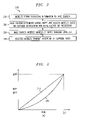
- FIG. 3 is a graph of transmission rate of a mobile versus normalized signal to noise ratio (NSNR) for a fixed cumulative NSNR and for an orthogonality factor between one-half and one;
- NSNR normalized signal to noise ratio
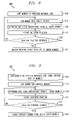
- FIG. 4 is a flow chart of an exemplary method that determines uplink mobile rates and produces an exact solution for the uplink mobile rates when an orthogonality factor is between one-half and one, in accordance with a preferred embodiment of the invention
- FIG. 5 is a flow chart of an alternate method that determines uplink mobile rates and also produces an exact solution for the uplink mobile rates when an orthogonality factor is between one-half and one, in accordance with a preferred embodiment of the invention
- FIG. 6 is a graph of transmission rate of a mobile versus NSNR for a fixed cumulative NSNR and for an orthogonality factor greater than zero but less than one-half;
- FIG. 7 is a flow chart of an exemplary method that determines uplink mobile rates and produces an exact solution for the uplink mobile rates when an orthogonality factor is between zero and one-half, in accordance with a preferred embodiment of the invention
- FIG. 8 is a flow chart of an exemplary method that determines uplink mobile rates and produces an approximate solution for the uplink mobile rates when an orthogonality factor is between one-half and one, in accordance with a preferred embodiment of the invention
- FIG. 9 is a flow chart of an exemplary proportional fair (PF) method, more specifically referred to as uplink PF (UPF) method herein, that determines uplink mobile rates and produces an approximate solution for the uplink mobile rates when an orthogonality factor is between one-half and one, in accordance with a preferred embodiment of the invention;
- PF proportional fair
- FIG. 10 is a flow chart of an exemplary average signal to interference ratio (SIR) method that determines uplink mobile rates and produces an approximate solution for the uplink mobile rates when an orthogonality factor is between one-half and one, in accordance with a preferred embodiment of the invention;
- SIR signal to interference ratio
- FIG. 11 is a flow chart of an exemplary successive interference cancellation (SIC) queue method that determines uplink mobile rates and produces an approximate solution for the uplink mobile rates, in accordance with a preferred embodiment of the invention.
- SIC successive interference cancellation
- FIG. 12 is a flow chart of an exemplary SIC method that determines uplink mobile rates and produces an approximate solution for the uplink mobile rates, in accordance with a preferred embodiment of the invention.
- the present disclosure is divided into sections, as follows: Introduction; Feasible Rate Region for Single Cell Uplink Scheduling; Optimal Uplink Scheduling; Role of Partial Orthogonality in Uplink Scheduling; Low-Complexity Approximation Techniques; and Successive Interference Cancellation (SIC) Techniques.
- Introduction Feasible Rate Region for Single Cell Uplink Scheduling
- Optimal Uplink Scheduling Role of Partial Orthogonality in Uplink Scheduling
- Low-Complexity Approximation Techniques Low-Complexity Approximation Techniques
- SIC Successive Interference Cancellation
- aspects of the present invention focus on scheduling with instantaneous constraints on transmit power and without the assumptions used in the information theoretic approaches. Additionally, aspects of the present invention can use feedback-based knowledge of channel conditions and mobile queues in order to improve uplink rates.
- the problem of optimal uplink scheduling of uplink mobile transmissions in a single CDMA cell, with a single base station is examined and solutions are presented that can determine an optimal solution to the uplink scheduling. Additionally, approximate solutions to the optimal uplink scheduling are developed. Optimal uplink scheduling produces an exact solution for uplink transmissions, whereas the approximate solutions produce inexact solutions. In other words, a maximum amount of data is transmitted on the uplink when using an optimal uplink scheduling technique. Exceeding the maximum amount of data is not possible.
- optimal uplink scheduling embodiments are typically computationally intensive and sub-optimal uplink scheduling embodiments often produce suitable scheduling with less computation.
- using the optimal uplink scheduling techniques herein may produce less than optimal results, due to rounding and other computational errors.
- a system using the techniques of the present invention operates in a time-division, CDMA manner, with time-period scheduling of CDMA transmissions, assisted in certain embodiments by periodic feedback of channel and congestion information through control channels.
- embodiments of the present invention will be described in relation to CDMA networks, the embodiments of the present invention are applicable to other wireless networks using uplink scheduling.
- the base station then controls mobile transmission rates via downlink signaling in certain embodiments.
- optimal techniques for uplink scheduling provided herein are reasonably well approximated by some very simple scheduling techniques, also described below, that may be implemented with modest effort in 3G systems.
- portion 100 is a cell of a CDMA network, and portion 100 comprises a base station 103 in communication with mobiles 140 - 1 through 140 - 4 (collectively, mobiles 140 ) and network 130 .
- Base station 103 comprises an antenna 125 , a processor 105 , a memory 110 , and a network interface 115 .
- Processor 105 comprises an uplink scheduling process 120 .
- Memory 110 comprises gain factors 111 - 1 through 111 - 4 (collectively, gain factors 111 ) and received powers 112 - 1 through 112 - 4 (collectively, received powers 112 ), one for each mobile 140 .
- Each mobile 140 comprises a processor 143 coupled to a memory 147 , and an antenna 145 .
- Each memory 147 in each mobile comprises a queue length 150 , a maximum transmit power 160 , and a rate limit 165 , each of which may be used in embodiments of the present invention.
- Each processor 143 runs one or more programs (not shown) that provide uplink and downlink communications with base station 103 .
- Each mobile 140 communicates with the base station 103 through an uplink 180 and a downlink 185 .
- FIG. 1 is used for illustrative purposes and is used to describe embodiments of the invention. However, FIG. 1 is in no way limiting.
- Network 130 is any suitable network for connecting to a base station 103 , such as the Internet, an asynchronous transfer mode (ATM) network or a plain old telephone system (POTS) network.
- Uplink scheduling process 120 comprises one or more of the methods shown in FIGS. 4 , 5 and 7 through 12 , which are used to determine appropriate uplink schedules for mobiles 140 .
- Uplink scheduling process 120 will communicate, in certain embodiments, the uplink schedule to mobiles 140 by using the downlink 185 .
- Uplink scheduling process 120 may reside in memory 110 and be loaded into processor 105 during execution. Alternatively, uplink scheduling process 120 may be partially or completely implemented in hardware, such as implemented in processor 105 .
- Processor 105 may be singular or distributed and may be any type of device adapted to perform instructions, such as a digital signal processor, gate array, programmable device, or general use processor.
- Memory 110 may be singular or distributed and may comprise static or dynamic memory or a combination thereof. Memory 110 may be at least in part magnetic or optical memory rather than electronic memory.
- mobiles 140 transmit information to the base station 103 .
- queue lengths 150 are used to provide measures of how much information the mobile 140 has yet to send.
- Mobiles 140 can transmit pilot signals to base station 103 , from which the base station 103 can determine gain factors 111 .
- the gain factors 111 and maximum transmit powers 160 are used, in certain embodiments, to determine received powers 112 from the mobiles 140 .
- maximum transmit powers 160 may be assumed.
- Rate limits 165 are used to determine whether a mobile can transmit only at a particular rate, and rate limits 165 will affect received powers 112 , as described in more detail below.
- a strong mobile 140 - 1 illustrates, for certain embodiments herein, a strong mobile 140 - 1 and a set 170 of weak mobiles 140 - 2 through 140 - 4 , from which a mobile or mobiles to transmit in the next time period are selected.
- the “strong” and “weak” mobiles are determined by the technique (e.g. described in reference to FIGS. 4 , 5 , 7 through 10 , and 12 ) determining which mobiles are to transmit during a time period.
- a “weak” mobile is a mobile with low received power at the base even when transmitting at peak transmit power, and a “strong” mobile with high received power at the base station 103 .
- a mobile with received power of zero decibels could be considered strong and all other mobiles considered weak.
- other criteria may be used to differentiate weak and strong mobiles.
- embodiments of the present invention optimize mobile QoS measures (e.g., queue lengths or delays) using knowledge about instantaneous queue length (or delay) status of a mobile and instantaneous channel conditions experienced by the mobile.
- aspects of the present invention also provide a greater degree of fairness, in addition to improved throughput, compared to widely used scheduling algorithms.
- the effect of limited orthogonality among the mobile codes is also considered below through an examination of the orthogonality factor (f), which, it is shown below, tends to encourage simultaneous mobile transmission due to reduced interference.
- f orthogonality factor
- UPF Uplink PF
- methods herein may be embodied as one or more programs placed on an article of manufacture, which comprises a machine readable medium containing one or more programs which, when executed, implement the steps of the methods.
- Method 200 is performed by uplink scheduling process 120 in order to determine appropriate uplink mobile rates and to inform mobiles as to which mobiles should transmit during a time period.
- Method 200 begins when one or more of the mobiles report individual information to the base station. For instance, queue lengths, maximum transmit powers, and rate limits may be communicated by the mobiles to the base station.
- the communication in step 210 is generally periodic.
- maximum transmit power may be assumed for many CDMA systems.
- the maximum transmit power can either be reported by the mobile once upon call-origination, or simply taken as a standard feature in mobiles.
- the mobiles have a standard, fixed, limited maximum transmit power.
- mobiles are generally not held to any rate limit.
- the base station should be made aware of this by feedback, via the rate limit that is transmitted from a mobile to the base station, to compute the maximum received power.
- weights e.g., queue lengths
- gain factors e.g., gain factors
- maximum power limits are beneficial.
- the queue length is beneficial.
- the base station determines the mobile rates and selects mobiles to transmit in a particular time period based on the supplied information and measurements (e.g., calculated received power) or predictions (e.g., an estimated maximum transmit power).
- FIGS. 4 and 5 describe optimal uplink scheduling determination;
- FIG. 7 describes optimal uplink scheduling determination when the orthogonality factor is less than one-half;
- FIG. 8 describes a sub-optimal uplink scheduling determination;
- FIG. 9 describes a sub-optimal uplink scheduling determination using a modified PF methodology;
- FIG. 10 describes a sub-optimal uplink scheduling determination using an average SIR methodology; and FIGS.
- 11 and 12 describe sub-optimal uplink scheduling determinations using SIC methodology.
- optimal uplink scheduling techniques exactly determine uplink schedules. Nonetheless, optimal uplink scheduling techniques may be impractical for certain real-time applications, and sub-optimal uplink scheduling techniques are therefore beneficial. Additionally, the performance and throughput loss due to the sub-optimal uplink scheduling techniques is generally small.
- the base station notifies the mobiles of the selected rates.
- the notification occurs on the downlink and may occur in different ways. For instance, only those mobiles selected for transmission in the particular time period (generally, the next time period) may be communicated with over the downlink.
- the rates for the mobile or mobiles may be transmitted to only those mobiles selected. Alternatively, all mobiles may be communicated to during one downlink communication.
- each mobile selected to transmit during a time period will transmit at maximum power and at a rate determined in step 220 . This occurs in step 240 , when the selected mobiles transmit, at the rates supplied by the base station, during the time period.
- the time period is the next time period for transmission.
- Equation (1) P i P _ i allows Equation (1) to be rewritten as the following:
- Equation (2) A given SIR vector ⁇ , is feasible if Equation (2) can be satisfied with equality with 0 ⁇ i ⁇ 1 for all i.
- ⁇ i ⁇ i P _ i ⁇ ( 1 + ⁇ i ) ⁇ 1 [ 1 - ⁇ j ⁇ ⁇ 1 ⁇ ⁇ N ⁇ ⁇ ⁇ ⁇ j 1 + ⁇ j ] . ( 4 ) Defining
- Equations (6) collapse into the single condition
- the feasible SIR region has a fully concave boundary which is dominated by its convex hull composed by time-sharing single mobile transmissions.
- the optimal scheduling strategy involves time-sharing over different subsets of simultaneously transmitting mobiles.
- An interesting observation regarding the optimal strategy, that is described below, is that all transmitting mobiles should transmit at full power, i.e. at P i , for certain embodiments of the present invention.
- the overall scheduling approach described herein for optimal uplink scheduling uses a weighted sum of mobile rates that is maximized for each scheduling interval. This choice has provable stability properties in various contexts involving data scheduling and resource allocation.
- the weights may be chosen to optimize one of many possible performance measures, including average queue length, delay, or corresponding percentiles, and other similar criteria.
- uplink scheduling techniques using queue length are described in more detail, but the weight can be any possible performance measure.
- a version of a methodology that guarantees queue stability, i.e., boundedness of queue lengths when feasible, is specified as the rate choice that satisfies the following:
- R * arg ⁇ ⁇ max R ⁇ R ⁇ ⁇ Q ⁇ R , where R, Q are rate and queue vectors of the mobile set respectively, and is the rate region, or the set of feasible rate vectors. Minimum or maximum instantaneous rate guarantees may be satisfied by restricting the rate region appropriately.
- R * arg ⁇ ⁇ max R ⁇ R ⁇ ⁇ w ⁇ R , ( 7 ) for arbitrary given weights w.
- Equation (7) a relationship between rate and SIR, as
- Equation (7) then becomes the following optimization problem:
- ⁇ j 1 N ⁇ ⁇ ⁇ j + ⁇ i P _ i ⁇ 1 , ⁇ i ⁇ 0 ⁇ ⁇ ⁇ i .
- g i ( ⁇ ) and g( ⁇ ) are identical functions, as is the case for the Shannon formula, but the results herein remain unaffected even if the functions were all different, as long as the functions stay convex.
- Equations (8) and (9) are rewritten as the following:
- Equations (10) and (11) have a simple “greedy” solution when g i ( ⁇ ) is convex.
- FIG. 3 shows how rate varies with the NSNR.
- the rate curve 320 is convex.
- the rate curve 320 is replaced for many embodiments described below by straight line 310 that joins the endpoints. This is valid on account of the theorem described above, which implies that the ⁇ i always take one of the bounding values (i.e., either zero or ⁇ ) in the constraints of Equations (11) if the cumulative NSNR, ⁇ , is appropriately chosen.
- Method 400 shown in FIG. 4 is called the “optimal method” herein.
- Method 400 is used by a base station to determine uplink mobile rates and which mobiles should transmit during a time period.
- v i w i ⁇ _ i ⁇ g i ⁇ ( ⁇ _ i ) , which is called the weighted marginal rate herein.
- step 420 the NSNR for the mobile with the best weighted marginal rate, which in this example is the highest weighted marginal rate, is assigned the highest NSNR for the mobile.
- assign ⁇ i ⁇ i for the mobile with the highest value of v i .
- step 425 the cumulative NSNR is updated as ⁇ ⁇ i .
- the best objective function is the objective function with the highest value, although potentially objective functions to be minimized may be chosen.
- ⁇ * ⁇ i ⁇ S ⁇ ⁇ P _ i ⁇ ( 1 - ⁇ * ) for the optimal value ⁇ *, where S is the optimal transmitting set.
- method 500 of FIG. 5 is used by a base station to determine uplink mobile rates and to determine which mobiles should transmit during a time period.
- Method 500 is termed the “alternate optimal method” herein. Because method 500 only selects some of the cumulative NSNRs, method 500 is faster than method 400 .
- step 515 For each interval [ ⁇ m , ⁇ m+1 ] (step 515 ), determine the mobile ordering in some interior point, say the midpoint, according to decreasing values of v i . The ordering is performed in step 520 .
- the complexity of method 500 for N mobiles is O(N 3 log N), and should give the optimal uplink scheduling solution.
- methods 400 and 500 can be modified to incorporate rate limits.
- the steps of methods 400 and 500 can be repeated when there are specified upper and lower bounds on individual mobile rates, i.e. R i min ⁇ R i ⁇ R i max .
- This condition can be transformed to ⁇ i min ⁇ i ⁇ i max using the functions g i ( ⁇ ).
- the lower rate limits may arise due to real-time services, and the upper limits may arise from transmitter capabilities or current queue content. These limits further favor simultaneous transmission, and must be included in the formulation for QoS, and power efficiency reasons.
- the methods 400 and 500 and methods described below can accommodate rate limits in the optimization by modifying Equation (11) as ⁇ i min ⁇ i ⁇ min ⁇ P i (1 ⁇ ), ⁇ i max ⁇ , but the somewhat more elaborate solution procedure will not be described here. Simple inspection reveals the changes necessary in the previous methods, which entail only a small computational overhead.
- the effect is now considered of partial orthogonality in the Walsh codes, for CDMA systems, assigned to mobiles.
- This effect is traditionally modeled by means of an orthogonality factor, f, which specifies the fraction of power transmitted to other mobiles that appears as direct interference to a particular mobile.
- f orthogonality factor
- Equation (8) and (9) changes to the following:
- g( ⁇ ) is convex for f ⁇ [0.5,1], but not so for f ⁇ [0,0.5).
- the effect of this on scheduling is to favor simultaneous transmission of mobiles, and at power levels smaller than the peak. This is due to the fact that concave maximization problems typically have their optima in the interior of the feasible region. It seems reasonable that other choices of the function g i (.) will reveal similar traits, since reducing f to very small values eliminates interference, and eventually favors simultaneous transmission by all mobiles in an interference-free manner.
- FIG. 6 shows the following critical values of ⁇ which will be used in the solution procedure discussed later: the upper limit for each mobile is
- ⁇ _ i ⁇ ⁇ ⁇ min ⁇ ( ⁇ , f ⁇ P _ i ⁇ ( 1 - ⁇ ) , ⁇ i max ) ; the inflection point is
- FIG. 7 is used by a base station to determine mobile rates and which mobiles should transmit during a time period when the orthogonality factor is f ⁇ [0,0.5).
- the method 700 proceeds as follows.
- step 710 a cumulative NSNR is selected.
- the critical values of ⁇ *, ⁇ i , ⁇ tilde over ( ⁇ ) ⁇ i are computed in step 715 for the selected value of ⁇ .
- the mobiles are divided into 2 classes.
- the second class, “Class II,” has ⁇ i: ⁇ i > ⁇ * ⁇ . These mobiles have ⁇ tilde over ( ⁇ ) ⁇ i ⁇ * ⁇ ⁇ i .
- step 725 NO
- this method 700 is more computationally intensive compared to the f ⁇ [0.5,1] case, and the method 700 is included here for completeness.
- most codings employed result in f ⁇ 0.6, and the simpler solution (i.e., either optimal or sub-optimal, described below) applies.
- the optimal solutions to uplink scheduling may be too burdensome and computationally intensive to use in certain practical applications.
- the following sections describe simpler approximations to the optimal solutions, where the simpler approximations are motivated by the structure of the optimal solution and demonstrate comparable performance.
- the orthogonality factor is restricted to the f ⁇ [0.5,1] case, and a number of greedy, low-complexity, approximate solutions are provided to the convex maximization discussed before.
- the QRP method 800 begins in step 810 , when mobiles are sorted in decreasing order of the weighted marginal rate,
- step 815 the mobile i, in order starting from the top of the list, is added to a new list while maintaining and updating the value of the objective function,
- step 830 NO
- step 815 another mobile is added in step 815 .
- step 830 YES
- the previously added mobile is removed from the new list of added mobiles. The remaining mobiles on the new list then transmit at their peak powers and rates as computed.
- This simple method 800 captures most of the benefits of optimal uplink scheduling, and has the properties alluded to above.
- the chosen mobile sets from the above algorithm tend to be one of the following types: (1) a single “strong” mobile with high P i ; or (2) a group of “weak” mobiles with low P i , and often high Q i .
- This observation is consistent with the common intuition relating to the nature of interference in CDMA systems.
- simulations show that the simple method 800 provides improved performance over conventional scheduling techniques.
- the conventional proportional fair (PF) scheduling method was proposed and implemented by QualComm for third generation (3G) 1X Enhanced Voice Data Optimized (EVDO), High Data Rate, downlink.
- the conventional PF algorithm provides fairness among mobiles such that in the long run each mobile receives the same number of time periods of service. At the same time, conventional PF also takes advantage of channel variations (e.g., mobile diversity).
- uplink PF (UPF) method described in FIG. 9 has a benefit of the QRP method, which is to allow a single “strong” mobile or a group of “weak” mobiles to transmit.
- the UPF method 900 of FIG. 9 is used by a base station to determine an approximate solution to uplink scheduling.
- Method 900 begins in step 910 when mobiles are sorted in decreasing order of the weighted marginal rate,
- v i R i 0 R _ i , assuming no interference from other mobiles while computing R i 0 (i.e., the transmission rate for a mobile with no interference from other mobiles).
- R i is the average rate of mobile i, updated through a low pass filter in each scheduling interval. The latter is described in, for instance, A. Jalali et al., “Data Throughput of CDMA-HDR a High Efficiency-High Data Rate Personal Communication Wireless System,” in Proc. of IEEE VTC, vol. 3 (2000), the disclosure of which is hereby incorporated by reference.
- step 915 the mobile i, in order starting from the top of the list of weighted marginal rates, is added to a new list of mobiles while maintaining and updating the value of the objective function,
- step 930 NO
- One example of a method that performs less well in simulations than the QRP method described above is termed an “Average-SIR” method herein.
- the Average-SIR method the average SIR, ⁇ avg , is calculated among all mobiles with non-empty queues.
- Average-SIR method 1000 of FIG. 10 is used by a base station to determine uplink rates.
- Method 1000 begins in step 1010 when the group of mobiles below average SIR is denoted as a set (called “B” herein).
- B group of mobiles below average SIR
- C group of mobiles above average SIR
- step 1025 the rates of mobiles belonging to C (mobiles in C will transmit one-at-a-time) are recomputed.
- step 1030 the objective function for the mobiles in B is determined as follows:
- step 1035 the objective function for each mobile in the second set is determined.
- SIC Successive Interference Cancellation
- SIC is a well-known technique in the context of multi-user detection. For instance, see P. Patel et al., “Analysis of a Simple Successive Interference Cancellation Scheme in a DS/CDMA System,” IEEE Journal on Selected Areas in Comm., vol. 12, no. 5 (1994) and S. Verdu, “Multiuser Detection,” Cambridge University Press (1998), the disclosures of which are hereby incorporated by reference.
- SIC involves decoding a mobile after subtracting out the interference from all previously decoded mobiles, thus making the current mobile immune to the previously decoded mobiles.
- scheduling with SIC is analyzed more from a system queuing stability or QoS point of view without any assumptions on mobile channels or traffic statistics, and with instantaneous transmit power constraints for each mobile.
- instantaneous (e.g., short-term) feedback information is assumed in the form of queue lengths or delays for mobiles and channel state inferred from received power.
- Equation (10) is first derived to help formulate and solve the problem.
- Equation (16) Equation (16)
- the SICQ method 1100 is shown in FIG. 11 .
- Method 1100 is performed by a base station using SIC in order to decode mobiles.
- Method 1100 begins when the mobiles are ordered based on increasing order of queue length, so that Q 1 ⁇ Q 2 ⁇ . . . ⁇ Q N .
- the decoding order is fixed based on the increasing order of queue length.
- ⁇ i P _ i 1 + ⁇ j ⁇ i ⁇ ⁇ P _ j .
- step 1120 the mobiles are decoded at the base station in the chosen Q order (i.e., Q 1 ⁇ Q 2 ⁇ . . . ⁇ Q N ).
- multi-user detection is an advanced signal processing technique that takes advantage of “soft” decoding output from multiple received signals and combines many such samples of user outputs to obtain the best possible decoding performance. Correlations in user signals over time play a major role in the performance of MUD.
- MUD is a more sophisticated and complex decoding technique compared to SIC or matched filtering, both of which treat MAI (Multi-Access Interference) as noise to a particular user. More information on MUD is presented in Verdu, which has already been incorporated by reference above. It is assumed that a MUD method performs well enough for weak mobiles so as to provide service with negligible error rates.
- hybrid scheduling method 1200 (called the HYSICP/HYSICQ method herein) shown in FIG. 12 is proposed.
- Method 1200 is performed by a base station 103 using SIC in order to decode mobiles.
- Method 1200 begins when all mobiles transmit simultaneously in each time period. All mobiles transmit at maximum power. As mentioned earlier, past conventional techniques suggest scheduling the mobiles purely based on received power. The conventional techniques will be called “SICP methods” herein. In step 1215 , all strong mobiles are decoded according to the SICP method or the SICQ method ( FIG. 11 ). A reasonable threshold (say 0 dB) on either received SIR or received power can be used to distinguish strong mobiles from weak mobiles.
- step 1220 interference is subtracted from all decoded strong mobiles.
- step 1220 all weak mobiles are decoded with a MUD method.
- the proposed HYSICP/HYSICQ of FIG. 12 combines the gain of SIC for strong mobiles while weak mobiles are decoded with MUD after eliminating interference from strong mobiles, who are reliably decoded with SIC.
- Method 1200 is expected to perform better than pure SIC when decoding errors in SIC are significant. Additionally, it would be beneficial to take into account actual decoding error probabilities for SIC, which depends on the implementation. Thus, it would be beneficial to classify strong users as “correctly decodable with high probability using SIC.” Those mobiles that have less probability for being correctly decoded using SIC can be decoded via MUD. Thus, a threshold for probability may be used to determine strong and weak users.
Abstract
Description
where wi is a weight for mobile i,
for N mobiles, is used as the second metric to determine which mobiles should transmit in a time period. Multiple marginal rates are determined that correspond to multiple determined objective functions. In this example, multiple marginal rates and multiple determined objective functions correspond to a number of cumulative NSNRs. The best objective function is selected from the multiple determined objective functions. The selected mobile or mobiles corresponding to the best objective function are the mobile or mobiles selected to transmit during the time period.
where Ri 0 is the communication rate with no interference from mobiles and
and the selected mobile or mobiles are those mobiles used to determine the objective function and that do not cause the objective function to decrease. In other words, rates corresponding to selected mobiles are added to the objective function. Once the objective function decreases when a rate, corresponding to a newly added mobile, is added to the objective function, then the mobile or mobiles selected before the newly added mobile are the selected mobile or mobiles that will transmit in the time period.
allows Equation (1) to be rewritten as the following:
are first examined, which can be further rewritten as the following:
where C is a global parameter. The value of Cγ
which gives the final solution as the following:
Defining
the following can be seen:
Clearly, 0≦αi<1. Since 0≦θi≦1 is required, the set of Equations (5) result in the following:
Note the simple linear form of the feasible SIRs in the set of Equations (6) in terms of the αi, about which the following observations are made.
which is the simple, single-cell version of the well-known stability condition for uplink power control. In this case, as is shown later, the feasible SIR region has a fully concave boundary which is dominated by its convex hull composed by time-sharing single mobile transmissions.
where R, Q are rate and queue vectors of the mobile set respectively, and
for arbitrary given weights w.
is required for each mobile. It is assumed that this relationship is concave in the argument γ, as is the case for the Shannon formula for the additive white Gaussian noise (AWGN) channel where R=βlog(1+γ), where β is the bandwidth of the channel. Since Equations (6) are linear in
it is more convenient to consider the R, α relationship which is now convex for the Shannon formula g(α)=βlog[1/(1−α)]. The variable α is called a normalized signal to noise ratio (NSNR) herein. Equation (7) then becomes the following optimization problem:
subject to the following:
Typically gi(·) and g(·) are identical functions, as is the case for the Shannon formula, but the results herein remain unaffected even if the functions were all different, as long as the functions stay convex. Before discussing methods to solve Equations (8), (9), some useful properties of the optimal solution are observed.
Equations (8) and (9) are rewritten as the following:
subject to the following:
which is called the weighted marginal rate herein.
for the optimal value Λ*, where S is the optimal transmitting set. Thus, the role of Λ is mainly in ordering the mobiles in the best manner out of the N! possibilities, and once an ordering is chosen, it is simple to check the N different values
for optimality. Further, an ordering change only takes place when Λ=Λij specified by the solution to vi=vj for some i≠j. This condition hence specifies at most N(N−1)/2 ordering changes out of the N! possibilities, some of which may not lie in [0,1] and can therefore be discarded. From these considerations, the following computationally simpler algorithm, shown in
with the αi now defined as the following:
Further, the optimization problem of Equations (8) and (9) changes to the following:
subject to the following:
where gi(·) now also depend on f. It is instructive to consider the Shannon formula, for which
the inflection point is
and the critical tangent originating at {tilde over (α)} is obtained by solving the following:
λ is then determined by solving
(step 735) and set αi*=
assuming no interference from other mobiles while computing Ri 0, so that Ri 0 is the transmission rate for a mobile with no interference from other mobiles. In
(step 825), for the added mobiles, where the Ri used in
assuming no interference from other mobiles while computing Ri 0 (i.e., the transmission rate for a mobile with no interference from other mobiles).
(step 925) where Ri takes into account interference from all added mobiles. The new Ri is calculated in
For the ith mobile (i starts at 1) in C, let qr[i]=QiRi.
where it is implicitly assumed that the mobiles are ordered in some specific way. Note that the ordering is a crucial aspect of SIC, since it plays an important role in determining the mobiles target received powers through Equation (10). The ordering chosen above determines the decoding order of mobiles at the base-station, which is the inverse order N, . . . ,2,1.
to rewrite Equation (10) as the following:
which leads to the identity si=γi+(1+γi)Si−1, i.e., 1+Si=(1+γi)(1+Si−1). From these identities, it is clear that Equations (10) and (11) can be explicitly solved as the following:
which leads to the following:
where Ri=f(γi), subject to the feasibility constraints in Equation (14). The analytical results below assume the Shannon formula
With some modification of the methods, certain other choices f(.) can be used, but the nature of the optimal schedule derived below might not hold in general. In terms of the Si, the optimization problem is then the following:
subject to Si−Si−1≦
is jointly concave in Si and Si−1, but the solution is in general not explicit. With the Shannon formula, a surprisingly simple solution can be obtained, that is derived below. The objective function in Equation (16) can be rewritten as the following:
with the convention S0=0=QN+1. Recall that the optimal ordering of the mobiles is part of the problem, and still remains to be determined. To maximize Equation (16), one may now invoke the polymatroid structure of the rate region of SIC, as described in Tse, but a simple proof is given below for completeness. It can be proven that the optimal mobile order for the solution of Equation (16) is given by the condition Q1≧Q2≧ . . . ≧QN. For instance, consider two consecutive mobiles in given ordering with queue lengths Qi,Qi+1 and received powers Pi,Pi+1, respectively. Assume that Qj,Pj,j=1,2, . . . ,N are fixed and given, and the only unknown is the mobile ordering. The contribution of these two mobiles to the objective function in Equation (16) is given by the following:
subject to the following:
S i −S i−1 ≦
i.e., all mobiles transmit at full power. Throughput optimal uplink scheduling with SIC, called the “SICQ method” herein, hence involves the following steps for each scheduling interval.
if Qi≧Qi+1 for any fixed Qj,Pj,j=1,2, . . . ,N.
Claims (35)
Priority Applications (1)
| Application Number | Priority Date | Filing Date | Title |
|---|---|---|---|
| US10/305,614 US7158804B2 (en) | 2002-11-27 | 2002-11-27 | Uplink scheduling for wireless networks |
Applications Claiming Priority (1)
| Application Number | Priority Date | Filing Date | Title |
|---|---|---|---|
| US10/305,614 US7158804B2 (en) | 2002-11-27 | 2002-11-27 | Uplink scheduling for wireless networks |
Publications (2)
| Publication Number | Publication Date |
|---|---|
| US20040102202A1 US20040102202A1 (en) | 2004-05-27 |
| US7158804B2 true US7158804B2 (en) | 2007-01-02 |
Family
ID=32325471
Family Applications (1)
| Application Number | Title | Priority Date | Filing Date |
|---|---|---|---|
| US10/305,614 Active 2024-05-16 US7158804B2 (en) | 2002-11-27 | 2002-11-27 | Uplink scheduling for wireless networks |
Country Status (1)
| Country | Link |
|---|---|
| US (1) | US7158804B2 (en) |
Cited By (32)
| Publication number | Priority date | Publication date | Assignee | Title |
|---|---|---|---|---|
| US20060182022A1 (en) * | 2003-10-03 | 2006-08-17 | Saied Abedi | Virtually centralized uplink scheduling |
| US20060203713A1 (en) * | 2003-05-16 | 2006-09-14 | Rajiv Laroia | Efficient signal transmission methods and apparatus using a shared transmission resource |
| US20060285515A1 (en) * | 2005-06-16 | 2006-12-21 | Qualcomm Incorporated | Methods and apparatus for efficient providing of scheduling information |
| US20070171862A1 (en) * | 2006-01-25 | 2007-07-26 | Honeywell International Inc. | Media access control protocol for mobile ad hoc networks using CDMA and multiuser detection |
| US20070211669A1 (en) * | 2006-03-07 | 2007-09-13 | Bhupesh Manoharlal Umatt | Method and apparatus for searching radio technologies |
| US20070248035A1 (en) * | 2006-04-11 | 2007-10-25 | Nec Laboratories America, Inc. | Uplink Scheduler for Cellular Packet Access |
| US20080182580A1 (en) * | 2002-08-08 | 2008-07-31 | Qualcomm Incorporated | Method of creating and utilizing diversity in a multiple carrier communciation system |
| US20080205333A1 (en) * | 2007-02-28 | 2008-08-28 | Qualcomm Incorporated | Uplink scheduling for fairness in channel estimation performance |
| US20090017760A1 (en) * | 2007-07-10 | 2009-01-15 | Qualcomm Incorporated | Methods and apparatus for successive interference cancellation based on rate capping in peer-to-peer networks |
| US20090017850A1 (en) * | 2007-07-10 | 2009-01-15 | Qualcomm Incorporated | Methods and apparatus for successive interference cancellation based on transmit power control by interfering device with success probability adaptation in peer-to-peer wireless networks |
| US20090017759A1 (en) * | 2007-07-10 | 2009-01-15 | Qualcomm Incorporated | Methods and apparatus for active successive interference cancellation in peer-to-peer networks |
| US20090017783A1 (en) * | 2007-07-10 | 2009-01-15 | Qualcomm Incorporated | Methods and apparatus for active successive interference cancellation based on one rate feedback and probability adaptation in peer-to-peer networks |
| US20090017761A1 (en) * | 2007-07-10 | 2009-01-15 | Qualcomm Incorporated | Methods and apparatus for successive interference cancellation based on two rate feedback in peer-to-peer networks |
| US20090017762A1 (en) * | 2007-07-10 | 2009-01-15 | Qualcomm Incorporated | Methods and apparatus for successive interference cancellation based on three rate reports from interfering device in peer-to-peer networks |
| US20090080557A1 (en) * | 2007-09-20 | 2009-03-26 | Leif Wilhelmsson | Quality of Service Based Antenna Mapping for Multiple-Input Multiple-Output Communication Systems |
| US20090122736A1 (en) * | 2007-01-11 | 2009-05-14 | Qualcomm Incorporated | Using dtx and drx in a wireless communication system |
| US7623553B2 (en) * | 2003-11-03 | 2009-11-24 | Qualcomm Incorporated | Method, apparatus, and system for data transmission and processing in a wireless communication environment |
| US20100130220A1 (en) * | 2002-08-08 | 2010-05-27 | Qualcomm Incorporated | Wireless timing and power control |
| US20100255798A1 (en) * | 2009-04-01 | 2010-10-07 | Mung Chiang | Cross-layer power control and scheduling protocol |
| US20110044192A1 (en) * | 2008-02-19 | 2011-02-24 | Min Wang | Uplink Scheduling DSF Wireless Networks |
| US20110142150A1 (en) * | 2003-08-13 | 2011-06-16 | Qualcomm Incorporated | User specific downlink power control channel q-bit |
| US20120002743A1 (en) * | 2010-06-30 | 2012-01-05 | Charles Casimiro Cavalcante | Statistical Joint Precoding in Multi-Cell, Multi-User MIMO |
| US20120275421A1 (en) * | 2007-11-28 | 2012-11-01 | Motorola Mobility Llc | Techniques for aligning application output and uplink resource allocation in wireless communication systems |
| US8553595B2 (en) | 2003-02-19 | 2013-10-08 | Qualcomm Incorporated | Controlled superposition coding in multi-user communication systems |
| US9055603B2 (en) | 2009-10-29 | 2015-06-09 | Telefonaktiebolaget L M Ericsson (Publ) | Scheduling of up-link transmissions of a wireless communication system |
| US9356461B2 (en) | 2012-09-25 | 2016-05-31 | Google Technology Holdings, LLC | Methods and systems for rapid wireless charging where the low state of charge (SOC) temperature dependent charging current and low SOC temperature limit are higher than the high SOC temperature dependent charging current and high SOC temperature limit |
| US9419457B2 (en) | 2012-09-04 | 2016-08-16 | Google Technology Holdings LLC | Method and device with enhanced battery capacity savings |
| US9438293B2 (en) | 2014-08-05 | 2016-09-06 | Google Technology Holdings LLC | Tunable circuit elements for dynamic, per element power |
| US9472965B2 (en) | 2014-09-08 | 2016-10-18 | Google Technology Holdings LLC | Battery cycle life through smart overnight charging |
| US9491706B2 (en) | 2013-03-13 | 2016-11-08 | Google Technology Holdings LLC | Reduced-power transmitting from a communications device |
| US9596653B2 (en) | 2013-12-16 | 2017-03-14 | Google Technology Holdings LLC | Remedying power drain via a coverage map |
| US9865897B2 (en) | 2014-06-02 | 2018-01-09 | Google Llc | Stacked electrochemical cell with increased energy density |
Families Citing this family (23)
| Publication number | Priority date | Publication date | Assignee | Title |
|---|---|---|---|---|
| US7865800B2 (en) * | 2002-02-07 | 2011-01-04 | Board Of Regents, The University Of Texas System | System and method for cooperation diversity through coding |
| US8190163B2 (en) * | 2002-08-08 | 2012-05-29 | Qualcomm Incorporated | Methods and apparatus of enhanced coding in multi-user communication systems |
| US7720042B2 (en) * | 2004-04-02 | 2010-05-18 | Lg Electronics Inc. | Method for transmitting and receiving data signal in MIMO system |
| KR100856248B1 (en) * | 2004-08-17 | 2008-09-03 | 삼성전자주식회사 | METHOD FOR SCHEDULING UPLINK IN VoIP |
| GB2418105A (en) * | 2004-09-13 | 2006-03-15 | Fujitsu Ltd | Relative indicators used for scheduling of uplink transmissions |
| ATE391376T1 (en) * | 2004-10-01 | 2008-04-15 | Matsushita Electric Ind Co Ltd | QUALITY OF SERVICE AWARENESS CONTROL FOR UPWARD TRANSMISSIONS OVER ALLOCATED CHANNELS |
| US7630338B2 (en) * | 2005-04-13 | 2009-12-08 | Nokia Corporation | Techniques for radio link resource management in wireless networks carrying packet traffic |
| US8654712B2 (en) * | 2005-06-16 | 2014-02-18 | Qualcomm Incorporated | OFDMA reverse link scheduling |
| US9955438B2 (en) * | 2005-09-27 | 2018-04-24 | Qualcomm Incorporated | Method and apparatus for carrier allocation and management in multi-carrier communication systems |
| KR100800863B1 (en) * | 2005-10-27 | 2008-02-04 | 삼성전자주식회사 | Apparatus and method for determining uplink priority in a wireless mobile communication system |
| US8914015B2 (en) * | 2006-03-20 | 2014-12-16 | Qualcomm Incorporated | Grouping of users for MIMO transmission in a wireless communication system |
| KR101031723B1 (en) | 2006-10-26 | 2011-04-29 | 엘지전자 주식회사 | Method for reporting channel information in multiple antenna system |
| WO2008069794A1 (en) * | 2006-12-06 | 2008-06-12 | Thomson Licensing | A selection technique for use in a multiple-input multiple-output (mimo) system |
| KR100933161B1 (en) * | 2006-12-11 | 2009-12-21 | 삼성전자주식회사 | Method and apparatus for uplink scheduling of communication system |
| WO2009131662A1 (en) * | 2008-04-23 | 2009-10-29 | Bae Systems Information And Electronic Systems Integration Inc. | Assigning channels to users in wireless networks that incorporate multi-user detection (mud) |
| US8483737B2 (en) * | 2008-05-09 | 2013-07-09 | Telefonaktiebolaget Lm Ericsson (Publ) | Resource allocation in uplink OFDMA |
| KR100938420B1 (en) | 2008-08-21 | 2010-01-25 | (주)크리웨이브 | Data communication method between multiple stations and access point in a distributed coordination function(dcf) based wireless lan |
| JP5298748B2 (en) * | 2008-10-03 | 2013-09-25 | 富士通株式会社 | Wireless relay device, wireless terminal, and program |
| US8886755B1 (en) | 2009-12-09 | 2014-11-11 | Marvell International Ltd. | Method and apparatus for facilitating simultaneous transmission from multiple stations |
| US8549564B1 (en) | 2010-08-30 | 2013-10-01 | Sprint Communications Company L.P. | Wireless video uplink system that wirelessly broadcasts a network access provider identifier |
| TW201427447A (en) * | 2012-09-17 | 2014-07-01 | Interdigital Patent Holdings | Self-optimization of backhaul radio resources and small cell backhaul delay estimation |
| US20140219243A1 (en) * | 2013-02-07 | 2014-08-07 | Qualcomm Incorporated | Apparatus and methods of joint transmit power and resource management |
| WO2014179979A1 (en) * | 2013-05-10 | 2014-11-13 | Qualcomm Incorporated | SIGNALING OF ENHANCED POWER CONTROL FOR eIMTA INTERFERENCE MITIGATION |
Citations (6)
| Publication number | Priority date | Publication date | Assignee | Title |
|---|---|---|---|---|
| US6072784A (en) | 1997-07-25 | 2000-06-06 | At&T Corp. | CDMA mobile station wireless transmission power management with adaptive scheduling priorities based on battery power level |
| US20030028659A1 (en) * | 2001-06-29 | 2003-02-06 | Mesarina Malena Rosa | Low power scheduling for multimedia systems |
| US20030125040A1 (en) * | 2001-11-06 | 2003-07-03 | Walton Jay R. | Multiple-access multiple-input multiple-output (MIMO) communication system |
| US20040001429A1 (en) * | 2002-06-27 | 2004-01-01 | Jianglei Ma | Dual-mode shared OFDM methods/transmitters, receivers and systems |
| US20040017825A1 (en) * | 2002-07-26 | 2004-01-29 | Kenneth Stanwood | Scheduling method and system for communication systems that offer multiple classes of service |
| US6885868B1 (en) * | 1999-09-30 | 2005-04-26 | Nortel Networks Limited | Fair packet scheduler and scheduling method for packet data radio |
-
2002
- 2002-11-27 US US10/305,614 patent/US7158804B2/en active Active
Patent Citations (6)
| Publication number | Priority date | Publication date | Assignee | Title |
|---|---|---|---|---|
| US6072784A (en) | 1997-07-25 | 2000-06-06 | At&T Corp. | CDMA mobile station wireless transmission power management with adaptive scheduling priorities based on battery power level |
| US6885868B1 (en) * | 1999-09-30 | 2005-04-26 | Nortel Networks Limited | Fair packet scheduler and scheduling method for packet data radio |
| US20030028659A1 (en) * | 2001-06-29 | 2003-02-06 | Mesarina Malena Rosa | Low power scheduling for multimedia systems |
| US20030125040A1 (en) * | 2001-11-06 | 2003-07-03 | Walton Jay R. | Multiple-access multiple-input multiple-output (MIMO) communication system |
| US20040001429A1 (en) * | 2002-06-27 | 2004-01-01 | Jianglei Ma | Dual-mode shared OFDM methods/transmitters, receivers and systems |
| US20040017825A1 (en) * | 2002-07-26 | 2004-01-29 | Kenneth Stanwood | Scheduling method and system for communication systems that offer multiple classes of service |
Non-Patent Citations (7)
| Title |
|---|
| A. Jalali et al., "Data Throughput of CDMA-HDR a High Efficiency-High Data Rate Personal Communication Wireless System," in Proc. of IEEE VTC, vol. 3 (2000). |
| A. Sampath and J. Holtzman, "Access Control of Data in Integrated Voice/Data CDMA Systems: Benefits and Tradeoffs," IEEE Journal on Selected Areas in Comm., vol. 15, No. 8 (1997). |
| D. N. C. Tse, "Optimal Power Allocation over Parallel Gaussian Broadcast Channels," Dept. of Electrical Engineering and Computer Sciences, International Symposium on Information Theory, Ulm, Germany (1997). |
| G. Caire et al., "Achievable Rates in Multi-Antenna Broadcast," Allerton Conference (2000). |
| Kumaran et al., "Uplink Scheduling in CDMA Systems," 1-13, (2002). |
| P. Patel et al., "Analysis of a Simple Successive Interference Cancellation Scheme in a DS/CDMA System," IEEE Journal on Selected Areas in Comm., vol. 12, No. 5 (1994). |
| S. Verdu, "Multiuser Detection," Cambridge University Press, Chapter Seven, Decision-Driven Multiuser Detectors, 344-351 (1998). |
Cited By (70)
| Publication number | Priority date | Publication date | Assignee | Title |
|---|---|---|---|---|
| US9277470B2 (en) | 2002-08-08 | 2016-03-01 | Qualcomm Incorporated | Method of creating and utilizing diversity in a multiple carrier communication system |
| US8620332B2 (en) | 2002-08-08 | 2013-12-31 | Qualcomm Incorporated | Wireless timing and power control |
| US20080182580A1 (en) * | 2002-08-08 | 2008-07-31 | Qualcomm Incorporated | Method of creating and utilizing diversity in a multiple carrier communciation system |
| US8374613B2 (en) | 2002-08-08 | 2013-02-12 | Qualcomm Incorporated | Method of creating and utilizing diversity in a multiple carrier communication system |
| US20100130220A1 (en) * | 2002-08-08 | 2010-05-27 | Qualcomm Incorporated | Wireless timing and power control |
| US8553595B2 (en) | 2003-02-19 | 2013-10-08 | Qualcomm Incorporated | Controlled superposition coding in multi-user communication systems |
| US20100278034A9 (en) * | 2003-05-16 | 2010-11-04 | Rajiv Laroia | Efficient signal transmission methods and apparatus using a shared transmission resource |
| US20060203713A1 (en) * | 2003-05-16 | 2006-09-14 | Rajiv Laroia | Efficient signal transmission methods and apparatus using a shared transmission resource |
| US8593932B2 (en) | 2003-05-16 | 2013-11-26 | Qualcomm Incorporated | Efficient signal transmission methods and apparatus using a shared transmission resource |
| US8315662B2 (en) | 2003-08-13 | 2012-11-20 | Qualcomm Incorporated | User specific downlink power control channel Q-bit |
| US20110142150A1 (en) * | 2003-08-13 | 2011-06-16 | Qualcomm Incorporated | User specific downlink power control channel q-bit |
| US20060182022A1 (en) * | 2003-10-03 | 2006-08-17 | Saied Abedi | Virtually centralized uplink scheduling |
| US8160005B2 (en) | 2003-10-03 | 2012-04-17 | Fujitsu Limited | Virtually centralized uplink scheduling |
| US8059596B2 (en) | 2003-10-03 | 2011-11-15 | Fujitsu Limited | Virtually centralized uplink scheduling |
| US8054794B2 (en) | 2003-10-03 | 2011-11-08 | Fujitsu Limited | Virtually centralized uplink scheduling |
| US7660280B2 (en) * | 2003-10-03 | 2010-02-09 | Fujitsu Limited | Virtually centralized uplink scheduling |
| US20100098018A1 (en) * | 2003-10-03 | 2010-04-22 | Fujitsu Limited | Virtually Centralized Uplink Scheduling |
| US20100098017A1 (en) * | 2003-10-03 | 2010-04-22 | Fujitsu Limited | Virtually Centralized Uplink Scheduling |
| US20100099427A1 (en) * | 2003-10-03 | 2010-04-22 | Fujitsu Limited | Virtually Centralized Uplink Scheduling |
| US8184583B2 (en) | 2003-10-03 | 2012-05-22 | Fujitsu Limited | Virtually centralized uplink scheduling |
| US20100142469A1 (en) * | 2003-10-03 | 2010-06-10 | Fujitsu Limited | Virtually Centralized Uplink Scheduling |
| US8170068B2 (en) | 2003-11-03 | 2012-05-01 | Qualcomm Incorporated | Method, apparatus, and system for data transmission and processing in a wireless communication environment |
| US7623553B2 (en) * | 2003-11-03 | 2009-11-24 | Qualcomm Incorporated | Method, apparatus, and system for data transmission and processing in a wireless communication environment |
| US20100091798A1 (en) * | 2003-11-03 | 2010-04-15 | Qualcomm Incorporated | Method, apparatus, and system for data transmission and processing in a wireless communication environment |
| US8098667B2 (en) | 2005-06-16 | 2012-01-17 | Qualcomm Incorporated | Methods and apparatus for efficient providing of scheduling information |
| US20060285515A1 (en) * | 2005-06-16 | 2006-12-21 | Qualcomm Incorporated | Methods and apparatus for efficient providing of scheduling information |
| US8634424B2 (en) | 2005-06-16 | 2014-01-21 | Qualcomm Incorporated | Methods and apparatus for efficient providing of scheduling information |
| US20070171862A1 (en) * | 2006-01-25 | 2007-07-26 | Honeywell International Inc. | Media access control protocol for mobile ad hoc networks using CDMA and multiuser detection |
| US20070211669A1 (en) * | 2006-03-07 | 2007-09-13 | Bhupesh Manoharlal Umatt | Method and apparatus for searching radio technologies |
| US7839830B2 (en) * | 2006-04-11 | 2010-11-23 | Nec Laboratories America, Inc. | Uplink scheduler for cellular packet access |
| US20070248035A1 (en) * | 2006-04-11 | 2007-10-25 | Nec Laboratories America, Inc. | Uplink Scheduler for Cellular Packet Access |
| US9674786B2 (en) | 2007-01-11 | 2017-06-06 | Qualcomm Incorporated | Using DTX and DRX in a wireless communication system |
| US9432942B2 (en) | 2007-01-11 | 2016-08-30 | Qualcomm Incorporated | Using DTX and DRX in a wireless communication system |
| US20090122736A1 (en) * | 2007-01-11 | 2009-05-14 | Qualcomm Incorporated | Using dtx and drx in a wireless communication system |
| US8755313B2 (en) | 2007-01-11 | 2014-06-17 | Qualcomm Incorporated | Using DTX and DRX in a wireless communication system |
| US20080205333A1 (en) * | 2007-02-28 | 2008-08-28 | Qualcomm Incorporated | Uplink scheduling for fairness in channel estimation performance |
| US8792922B2 (en) | 2007-02-28 | 2014-07-29 | Qualcomm Incorporated | Uplink scheduling for fairness in channel estimation performance |
| US20090017759A1 (en) * | 2007-07-10 | 2009-01-15 | Qualcomm Incorporated | Methods and apparatus for active successive interference cancellation in peer-to-peer networks |
| US20090017762A1 (en) * | 2007-07-10 | 2009-01-15 | Qualcomm Incorporated | Methods and apparatus for successive interference cancellation based on three rate reports from interfering device in peer-to-peer networks |
| US20090017760A1 (en) * | 2007-07-10 | 2009-01-15 | Qualcomm Incorporated | Methods and apparatus for successive interference cancellation based on rate capping in peer-to-peer networks |
| US20090017850A1 (en) * | 2007-07-10 | 2009-01-15 | Qualcomm Incorporated | Methods and apparatus for successive interference cancellation based on transmit power control by interfering device with success probability adaptation in peer-to-peer wireless networks |
| US8433349B2 (en) | 2007-07-10 | 2013-04-30 | Qualcomm Incorporated | Methods and apparatus for successive interference cancellation based on transmit power control by interfering device with success probability adaptation in peer-to-peer wireless networks |
| US9668225B2 (en) | 2007-07-10 | 2017-05-30 | Qualcomm Incorporated | Methods and apparatus for active successive interference cancellation based on one rate feedback and probability adaptation in peer-to-peer networks |
| US8874040B2 (en) | 2007-07-10 | 2014-10-28 | Qualcomm Incorporated | Methods and apparatus for successive interference cancellation based on rate capping in peer-to-peer networks |
| US20090017783A1 (en) * | 2007-07-10 | 2009-01-15 | Qualcomm Incorporated | Methods and apparatus for active successive interference cancellation based on one rate feedback and probability adaptation in peer-to-peer networks |
| US20090017761A1 (en) * | 2007-07-10 | 2009-01-15 | Qualcomm Incorporated | Methods and apparatus for successive interference cancellation based on two rate feedback in peer-to-peer networks |
| US8855567B2 (en) | 2007-07-10 | 2014-10-07 | Qualcomm Incorporated | Methods and apparatus for successive interference cancellation based on two rate feedback in peer-to-peer networks |
| US8849197B2 (en) | 2007-07-10 | 2014-09-30 | Qualcomm Incorporated | Methods and apparatus for active successive interference cancellation in peer-to-peer networks |
| US9521680B2 (en) | 2007-07-10 | 2016-12-13 | Qualcomm Incorporated | Methods and apparatus for successive interference cancellation based on three rate reports from interfering device in peer-to-peer networks |
| US20090080557A1 (en) * | 2007-09-20 | 2009-03-26 | Leif Wilhelmsson | Quality of Service Based Antenna Mapping for Multiple-Input Multiple-Output Communication Systems |
| US7929625B2 (en) | 2007-09-20 | 2011-04-19 | Telefonaktiebolaget Lm Ericsson (Publ) | Quality of service based antenna mapping for multiple-input multiple-output communication systems |
| US8755811B2 (en) * | 2007-11-28 | 2014-06-17 | Motorola Mobility Llc | Techniques for aligning application output and uplink resource allocation in wireless communication systems |
| US20120275421A1 (en) * | 2007-11-28 | 2012-11-01 | Motorola Mobility Llc | Techniques for aligning application output and uplink resource allocation in wireless communication systems |
| US9635650B2 (en) | 2007-11-28 | 2017-04-25 | Google Technology Holdings LLC | Techniques for aligning application output and uplink resource allocation in wireless communication systems |
| US8437269B2 (en) * | 2008-02-19 | 2013-05-07 | Telefonaktiebolaget Lm Ericsson (Publ) | Uplink scheduling DSF wireless networks |
| US20110044192A1 (en) * | 2008-02-19 | 2011-02-24 | Min Wang | Uplink Scheduling DSF Wireless Networks |
| US20100255798A1 (en) * | 2009-04-01 | 2010-10-07 | Mung Chiang | Cross-layer power control and scheduling protocol |
| US8068867B2 (en) * | 2009-04-01 | 2011-11-29 | Empire Technology Development Llc | Cross-layer power control and scheduling protocol |
| US9055603B2 (en) | 2009-10-29 | 2015-06-09 | Telefonaktiebolaget L M Ericsson (Publ) | Scheduling of up-link transmissions of a wireless communication system |
| US8934557B2 (en) * | 2010-06-30 | 2015-01-13 | Telefonaktiebolaget L M Ericsson (Publ) | Statistical joint precoding in multi-cell, multi-user MIMO |
| US20120002743A1 (en) * | 2010-06-30 | 2012-01-05 | Charles Casimiro Cavalcante | Statistical Joint Precoding in Multi-Cell, Multi-User MIMO |
| US9419457B2 (en) | 2012-09-04 | 2016-08-16 | Google Technology Holdings LLC | Method and device with enhanced battery capacity savings |
| US9356461B2 (en) | 2012-09-25 | 2016-05-31 | Google Technology Holdings, LLC | Methods and systems for rapid wireless charging where the low state of charge (SOC) temperature dependent charging current and low SOC temperature limit are higher than the high SOC temperature dependent charging current and high SOC temperature limit |
| US9491706B2 (en) | 2013-03-13 | 2016-11-08 | Google Technology Holdings LLC | Reduced-power transmitting from a communications device |
| US9596653B2 (en) | 2013-12-16 | 2017-03-14 | Google Technology Holdings LLC | Remedying power drain via a coverage map |
| US9949210B2 (en) | 2013-12-16 | 2018-04-17 | Google Technology Holdings LLC | Remedying power drain via a coverage map |
| US9865897B2 (en) | 2014-06-02 | 2018-01-09 | Google Llc | Stacked electrochemical cell with increased energy density |
| US9438293B2 (en) | 2014-08-05 | 2016-09-06 | Google Technology Holdings LLC | Tunable circuit elements for dynamic, per element power |
| US9472965B2 (en) | 2014-09-08 | 2016-10-18 | Google Technology Holdings LLC | Battery cycle life through smart overnight charging |
| US9847661B2 (en) | 2014-09-08 | 2017-12-19 | Google Llc | Extended battery cycle life through smart charging of rechargeable batteries |
Also Published As
| Publication number | Publication date |
|---|---|
| US20040102202A1 (en) | 2004-05-27 |
Similar Documents
| Publication | Publication Date | Title |
|---|---|---|
| US7158804B2 (en) | Uplink scheduling for wireless networks | |
| Kumaran et al. | Uplink scheduling in CDMA packet-data systems | |
| US8219036B2 (en) | Dynamic channel quality measurement procedure implemented in a wireless digital communication system to prioritize the forwarding of downlink data | |
| Oh et al. | Dynamic spreading gain control in multiservice CDMA networks | |
| KR100812575B1 (en) | Method and apparatus for high rate packet data and low delay data transmissions | |
| RU2285342C2 (en) | Method and device for determining data transfer speed in high speed wireless systems for transferring packet data | |
| US20060019665A1 (en) | Cellular communications systems | |
| US7924698B2 (en) | Proportional fair scheduler for OFDMA wireless systems | |
| US8077678B2 (en) | Radio resource allocating method and apparatus in adaptive antenna system | |
| US20020151310A1 (en) | Reverse rate control | |
| Agarwal et al. | Low complexity resource allocation with opportunistic feedback over downlink OFDMA networks | |
| US7577120B2 (en) | Allocation of power and channelization codes for data transfers | |
| CN113079577B (en) | Resource allocation method based on coexistence scene of EMBB and URLLC | |
| US6775256B1 (en) | Packet scheduler and method therefor | |
| US20120044846A1 (en) | Operation of a telecommunications system | |
| US20050195843A1 (en) | Group based packet scheduling algorithm | |
| US20230199720A1 (en) | Priority-based joint resource allocation method and apparatus with deep q-learning | |
| US8170031B2 (en) | High performance scheduling methods and apparatus for leveraging diversity in relay-enabled wireless networks | |
| US20020106002A1 (en) | Resource allocation in CDMA wireless communication systems | |
| Kumaran et al. | Scheduling on uplink of CDMA packet data network with successive interference cancellation | |
| Awal et al. | An integrated cross-layer framework of adaptive feedback resource allocation and prediction for ofdma systems | |
| CN101444132A (en) | Method and apparatus for mobile telecommunication network | |
| KR101136715B1 (en) | Packet Scheduling Algorithm considering a minimum delay time requirement for Non-realtime Traffic | |
| Baiocchi et al. | Optimizing the radio resource utilization of multiaccess systems with a traffic-transmission quality adaptive packet scheduling | |
| WO2022137274A1 (en) | Control device, communication system, control method, and non-transitory computer-readable medium |
Legal Events
| Date | Code | Title | Description |
|---|---|---|---|
| AS | Assignment |
Owner name: LUCENT TECHNOLOGIES INC., NEW JERSEY Free format text: ASSIGNMENT OF ASSIGNORS INTEREST;ASSIGNORS:KUMARAN, KRISHNAN;QIAN, LIJUN;REEL/FRAME:013832/0425 Effective date: 20021204 |
|
| FEPP | Fee payment procedure |
Free format text: PAYOR NUMBER ASSIGNED (ORIGINAL EVENT CODE: ASPN); ENTITY STATUS OF PATENT OWNER: LARGE ENTITY |
|
| STCF | Information on status: patent grant |
Free format text: PATENTED CASE |
|
| FPAY | Fee payment |
Year of fee payment: 4 |
|
| AS | Assignment |
Owner name: CREDIT SUISSE AG, NEW YORK Free format text: SECURITY INTEREST;ASSIGNOR:ALCATEL-LUCENT USA INC.;REEL/FRAME:030510/0627 Effective date: 20130130 |
|
| FPAY | Fee payment |
Year of fee payment: 8 |
|
| AS | Assignment |
Owner name: ALCATEL-LUCENT USA INC., NEW JERSEY Free format text: RELEASE BY SECURED PARTY;ASSIGNOR:CREDIT SUISSE AG;REEL/FRAME:033950/0261 Effective date: 20140819 |
|
| AS | Assignment |
Owner name: OMEGA CREDIT OPPORTUNITIES MASTER FUND, LP, NEW YORK Free format text: SECURITY INTEREST;ASSIGNOR:WSOU INVESTMENTS, LLC;REEL/FRAME:043966/0574 Effective date: 20170822 Owner name: OMEGA CREDIT OPPORTUNITIES MASTER FUND, LP, NEW YO Free format text: SECURITY INTEREST;ASSIGNOR:WSOU INVESTMENTS, LLC;REEL/FRAME:043966/0574 Effective date: 20170822 |
|
| AS | Assignment |
Owner name: WSOU INVESTMENTS, LLC, CALIFORNIA Free format text: ASSIGNMENT OF ASSIGNORS INTEREST;ASSIGNOR:ALCATEL LUCENT;REEL/FRAME:044000/0053 Effective date: 20170722 |
|
| FEPP | Fee payment procedure |
Free format text: MAINTENANCE FEE REMINDER MAILED (ORIGINAL EVENT CODE: REM.) |
|
| FEPP | Fee payment procedure |
Free format text: 11.5 YR SURCHARGE- LATE PMT W/IN 6 MO, LARGE ENTITY (ORIGINAL EVENT CODE: M1556); ENTITY STATUS OF PATENT OWNER: LARGE ENTITY |
|
| MAFP | Maintenance fee payment |
Free format text: PAYMENT OF MAINTENANCE FEE, 12TH YEAR, LARGE ENTITY (ORIGINAL EVENT CODE: M1553); ENTITY STATUS OF PATENT OWNER: LARGE ENTITY Year of fee payment: 12 |
|
| AS | Assignment |
Owner name: BP FUNDING TRUST, SERIES SPL-VI, NEW YORK Free format text: SECURITY INTEREST;ASSIGNOR:WSOU INVESTMENTS, LLC;REEL/FRAME:049235/0068 Effective date: 20190516 |
|
| AS | Assignment |
Owner name: WSOU INVESTMENTS, LLC, CALIFORNIA Free format text: RELEASE BY SECURED PARTY;ASSIGNOR:OCO OPPORTUNITIES MASTER FUND, L.P. (F/K/A OMEGA CREDIT OPPORTUNITIES MASTER FUND LP;REEL/FRAME:049246/0405 Effective date: 20190516 |
|
| AS | Assignment |
Owner name: OT WSOU TERRIER HOLDINGS, LLC, CALIFORNIA Free format text: SECURITY INTEREST;ASSIGNOR:WSOU INVESTMENTS, LLC;REEL/FRAME:056990/0081 Effective date: 20210528 |
|
| AS | Assignment |
Owner name: WSOU INVESTMENTS, LLC, CALIFORNIA Free format text: RELEASE BY SECURED PARTY;ASSIGNOR:TERRIER SSC, LLC;REEL/FRAME:056526/0093 Effective date: 20210528 |