US7159900B2 - Passenger side airbag module - Google Patents

Passenger side airbag module Download PDF

Info

Publication number
US7159900B2
US7159900B2 US10/826,012 US82601204A US7159900B2 US 7159900 B2 US7159900 B2 US 7159900B2 US 82601204 A US82601204 A US 82601204A US 7159900 B2 US7159900 B2 US 7159900B2
Authority
US
United States
Prior art keywords
airbag
gas
gas generator
instrument panel
disk
Prior art date
Legal status (The legal status is an assumption and is not a legal conclusion. Google has not performed a legal analysis and makes no representation as to the accuracy of the status listed.)
Expired - Fee Related, expires
Application number
US10/826,012
Other versions
US20040245754A1 (en
Inventor
Thomas Reiter
Karl Heinz Sommer
Jörg Albert
Current Assignee (The listed assignees may be inaccurate. Google has not performed a legal analysis and makes no representation or warranty as to the accuracy of the list.)
Autoliv Development AB
Original Assignee
Autoliv Development AB
Priority date (The priority date is an assumption and is not a legal conclusion. Google has not performed a legal analysis and makes no representation as to the accuracy of the date listed.)
Filing date
Publication date
Application filed by Autoliv Development AB filed Critical Autoliv Development AB
Assigned to AUTOLIV DEVELOPMENT AB reassignment AUTOLIV DEVELOPMENT AB ASSIGNMENT OF ASSIGNORS INTEREST (SEE DOCUMENT FOR DETAILS). Assignors: ALBERT, JORG, REITER, THOMAS, SOMMER, KARL HEINZ
Publication of US20040245754A1 publication Critical patent/US20040245754A1/en
Application granted granted Critical
Publication of US7159900B2 publication Critical patent/US7159900B2/en
Expired - Fee Related legal-status Critical Current
Adjusted expiration legal-status Critical

Links

Images

Classifications

    • BPERFORMING OPERATIONS; TRANSPORTING
    • B60VEHICLES IN GENERAL
    • B60RVEHICLES, VEHICLE FITTINGS, OR VEHICLE PARTS, NOT OTHERWISE PROVIDED FOR
    • B60R21/00Arrangements or fittings on vehicles for protecting or preventing injuries to occupants or pedestrians in case of accidents or other traffic risks
    • B60R21/02Occupant safety arrangements or fittings, e.g. crash pads
    • B60R21/16Inflatable occupant restraints or confinements designed to inflate upon impact or impending impact, e.g. air bags
    • B60R21/20Arrangements for storing inflatable members in their non-use or deflated condition; Arrangement or mounting of air bag modules or components
    • B60R21/205Arrangements for storing inflatable members in their non-use or deflated condition; Arrangement or mounting of air bag modules or components in dashboards
    • BPERFORMING OPERATIONS; TRANSPORTING
    • B60VEHICLES IN GENERAL
    • B60RVEHICLES, VEHICLE FITTINGS, OR VEHICLE PARTS, NOT OTHERWISE PROVIDED FOR
    • B60R21/00Arrangements or fittings on vehicles for protecting or preventing injuries to occupants or pedestrians in case of accidents or other traffic risks
    • B60R21/02Occupant safety arrangements or fittings, e.g. crash pads
    • B60R21/16Inflatable occupant restraints or confinements designed to inflate upon impact or impending impact, e.g. air bags
    • B60R21/26Inflatable occupant restraints or confinements designed to inflate upon impact or impending impact, e.g. air bags characterised by the inflation fluid source or means to control inflation fluid flow
    • B60R21/261Inflatable occupant restraints or confinements designed to inflate upon impact or impending impact, e.g. air bags characterised by the inflation fluid source or means to control inflation fluid flow with means other than bag structure to diffuse or guide inflation fluid

Definitions

  • the invention relates to a passenger airbag in a motor vehicle comprising a module installed behind the instrument panel of the vehicle, a disk-shaped gas generator mounted within the module, a deflector that at least partially surrounds the gas-discharge openings located on the perimeter of the disk-shaped gas generator, and an airbag that is connected to the gas generator and/or the deflector and folded into the module.
  • the module is installed behind at least one opening flap designed in the instrument panel.
  • a pot-shaped deflector surrounds the disk-shaped gas generator on the side opposite the folded airbag and its top open edge is directed into the connected airbag so that the deflector deflects the gas, which escapes radially from the gas-discharge openings of the gas generator, and guides it into the connected airbag.
  • the disk-shaped gas generator is designed to be installed behind the instrument panel of a motor vehicle in such a manner that the plane of the disk is aligned parallel to the plane of the instrument panel and the opening flap thereon.
  • the objective of the invention is therefore to design a generic passenger airbag having a disk-shaped gas generator in such a manner that the dimensions of the module and consequently of the required installation space behind the instrument panel of the vehicle are reduced.
  • the disk-shaped gas generator including the module surrounding it, is arranged on-edge at an angle to the plane of the instrument panel, its narrow side being defined by gas-discharge openings arranged on its perimeter, and the folded airbag is arranged at least partially between the narrow side of the gas generator and the opening flap.
  • the width of the airbag module and the installation space required therefor are basically restricted to the overall height of the disk-shaped generator. If the folded airbag comes to rest at least partially between the narrow side of the gas generator and the opening flap, at least part of the released gas will flow over the airbag due to the gas-discharge openings arranged on the perimeter of the disk-shaped gas generator, so that the opening characteristics of both the folded airbag and the opening flap that it pressurizes are improved.
  • the deflector surround the disk-shaped gas generator in the peripheral area opposite the opening flap in order to guide the gas flow escaping from the gas-discharge openings arranged in this area into the airbag folded between the gas generator and opening flap.
  • the use of a deflector arranged in this manner advantageously provides the possibility of installing additional particle filters in the installation space of the deflector; moreover, additional guide vanes may be provided for gas deflection.
  • the deflector can reduce the tensile forces that occur in the airbag.
  • the deflector may moreover be applied to dividing the folded airbag into different airbag packages and thus provide the folded airbag with an orientation regarding the approach flow and unfolding.
  • the deflector may also be fastened to the modular casing by additional fastening means, like plugs or screws; but it may also be provided that the deflector is fastened by gluing or welding or by a combination of the aforementioned fastening procedures.
  • the deflector may surround the gas generator completely or partially. If the gas generator is only partially surrounded, then the module casing will take over the function of gas deflection.
  • one exemplary embodiment of the invention provides that the disk-shaped generator, whose plane is defined by the gas-discharge openings, be aligned normal to the surface of the opening flap.
  • one exemplary embodiment of the invention provides that the disk-shaped gas generator, whose plane is defined by the gas-discharge openings, make an angle of no more than 50° from normal to the surface of the opening flap, wherein the corresponding angle may be aligned normal to the surface of the opening flap on both sides.
  • a subsection of the deflector cover the gas-discharge openings directed toward the opening flap, this will prevent the incompletely unfolded airbag package from accelerating in the direction of the vehicle occupant, possibly reducing the load acting on the occupant when the airbag unfolds.
  • the reduction of the required installation space provides the possibility of even accommodating two gas generators within the module casing for sequential unfolding of connected airbags or airbag areas, wherein these gas generators may be arranged side-by-side or one behind the other relative to the instrument panel.
  • FIG. 1 is a top view of an instrument panel having an airbag module connected to the opening flap on the narrow side,
  • FIG. 2 illustrates a side view cut according to line 2 — 2 in FIG. 1 ,
  • FIG. 3 illustrates a top view cut according to the line 3 — 3 in FIG. 2 ,
  • FIG. 4 illustrates a top view cut according to line 4 — 4 in FIG. 2 .
  • FIG. 5 illustrates the top view of FIG. 3 with two gas generators
  • FIG. 6 illustrates the top view of FIG. 5 with an alternate arrangement of two gas generators.
  • FIG. 1 from the top view of the instrument panel 10 , including the airbag module with an opening flap 11 provided in the instrument panel.
  • a module casing 12 having a disk-shaped gas generator 13 is connected behind the opening flap 11 in such a manner that the narrow side of the disk-shaped generator 13 is arranged on-edge to the plane of the instrument panel 10 , at a right angle in the generator 13 (and its central axis 19 ) is aligned generally parallel to the plane of the instrument panel 10 .
  • Gas generator 13 is of a type having its height or thickness (measured along axis 19 ) substantially less than its diameter.
  • a deflector 14 which in the illustrated exemplary embodiment is fastened by fastening plugs 16 feeding through the module casing 12 , is arranged in the interior of the module casing 12 in addition to the gas generator 13 .
  • the deflector 14 On its edges that are directed to the opening flap 11 of the instrument panel 10 , the deflector 14 surrounds an airbag 15 , which has already unfolded out of the module casing 12 in the exemplary embodiment depicted in FIG. 2 .
  • the airbag 15 is connected to the modular casing 12 and deflector 14 by fastening plugs 16 and partially surrounds the deflector 14 .
  • a subsection 18 of the deflector 14 partially covers a portion of the perimeter of the gas generator 13 in the central area in such a manner that the radially flowing gas cannot directly act upon the airbag 15 folded in this area but is diverted.
  • the disk-shaped gas generator 13 includes gas-discharge openings 17 on its outer perimeter through which the gas is released when the gas generator is triggered. This representation is further explained by FIG. 4 .

Abstract

An airbag module in a motor vehicle having a modular casing installed behind at least one opening flap built into the instrument panel is characterized in that the disk-shaped gas generator, including the modular casing surrounding it, is arranged on-edge at an angle to the plane of the instrument panel, its narrow side being defined by the gas-discharge openings arranged on its perimeter, and the folded airbag is arranged at least partially between the narrow side of the gas generator and the opening flap.

Description

CROSS REFERENCE TO RELATED APPLICATION
This application claims priority to German patent application number 103 17 833.3, filed Apr. 16, 2003 which is currently pending.
BACKGROUND AND SUMMARY OF THE INVENTION
The invention relates to a passenger airbag in a motor vehicle comprising a module installed behind the instrument panel of the vehicle, a disk-shaped gas generator mounted within the module, a deflector that at least partially surrounds the gas-discharge openings located on the perimeter of the disk-shaped gas generator, and an airbag that is connected to the gas generator and/or the deflector and folded into the module. The module is installed behind at least one opening flap designed in the instrument panel.
An airbag with the abovementioned characteristics is described in US 2002/0149177 A1; in which a disk-shaped gas generator with gas-discharge openings arranged on its perimeter is arranged within a module casing in such a manner that the folded airbag engages the gas generator and its gas inlet openings and is thereby connected to the gas generator and is folded up on the surface of the disk-shaped gas generator.
A pot-shaped deflector surrounds the disk-shaped gas generator on the side opposite the folded airbag and its top open edge is directed into the connected airbag so that the deflector deflects the gas, which escapes radially from the gas-discharge openings of the gas generator, and guides it into the connected airbag. The disk-shaped gas generator is designed to be installed behind the instrument panel of a motor vehicle in such a manner that the plane of the disk is aligned parallel to the plane of the instrument panel and the opening flap thereon.
This mounting position of the disk-shaped gas generator has the disadvantage that, due to the large diameter of the disk-shaped generator inherent in its design, the module casing required therefor must be built accordingly large. In modern vehicles, there are constraints on available installation space because less and less installation space for airbag modules is available due, in particular, to the growing demand for ventilation channels built in behind the instrument panel. If airbag modules with tubular gas generators are built narrower, then other disadvantages are associated with the use of tubular gas generators, such as more expenses for sealing and connecting the airbag within the modular casing.
The objective of the invention is therefore to design a generic passenger airbag having a disk-shaped gas generator in such a manner that the dimensions of the module and consequently of the required installation space behind the instrument panel of the vehicle are reduced.
The solution of this objective, including advantageous embodiments and further developments of the invention, results from the contents of the claims that follow this description.
SUMMARY OF THE INVENTION
The basic idea of the invention is that the disk-shaped gas generator, including the module surrounding it, is arranged on-edge at an angle to the plane of the instrument panel, its narrow side being defined by gas-discharge openings arranged on its perimeter, and the folded airbag is arranged at least partially between the narrow side of the gas generator and the opening flap.
With the invention there is associated the advantage that the width of the airbag module and the installation space required therefor are basically restricted to the overall height of the disk-shaped generator. If the folded airbag comes to rest at least partially between the narrow side of the gas generator and the opening flap, at least part of the released gas will flow over the airbag due to the gas-discharge openings arranged on the perimeter of the disk-shaped gas generator, so that the opening characteristics of both the folded airbag and the opening flap that it pressurizes are improved.
According to one exemplary embodiment of the invention, it is provided that the deflector surround the disk-shaped gas generator in the peripheral area opposite the opening flap in order to guide the gas flow escaping from the gas-discharge openings arranged in this area into the airbag folded between the gas generator and opening flap. In addition to the deflection of the gas escaping from the gas-discharge openings that this effects, the use of a deflector arranged in this manner advantageously provides the possibility of installing additional particle filters in the installation space of the deflector; moreover, additional guide vanes may be provided for gas deflection. In inflating the airbag, the deflector can reduce the tensile forces that occur in the airbag.
In accordance with this invention, the deflector may moreover be applied to dividing the folded airbag into different airbag packages and thus provide the folded airbag with an orientation regarding the approach flow and unfolding. The deflector may also be fastened to the modular casing by additional fastening means, like plugs or screws; but it may also be provided that the deflector is fastened by gluing or welding or by a combination of the aforementioned fastening procedures. The deflector may surround the gas generator completely or partially. If the gas generator is only partially surrounded, then the module casing will take over the function of gas deflection.
In regard to the mounting position of the gas generator and module, one exemplary embodiment of the invention provides that the disk-shaped generator, whose plane is defined by the gas-discharge openings, be aligned normal to the surface of the opening flap. In regard to an angular arrangement of the gas generator to the module, one exemplary embodiment of the invention provides that the disk-shaped gas generator, whose plane is defined by the gas-discharge openings, make an angle of no more than 50° from normal to the surface of the opening flap, wherein the corresponding angle may be aligned normal to the surface of the opening flap on both sides.
If it is provided, according to one exemplary embodiment of the invention, that a subsection of the deflector cover the gas-discharge openings directed toward the opening flap, this will prevent the incompletely unfolded airbag package from accelerating in the direction of the vehicle occupant, possibly reducing the load acting on the occupant when the airbag unfolds.
The reduction of the required installation space provides the possibility of even accommodating two gas generators within the module casing for sequential unfolding of connected airbags or airbag areas, wherein these gas generators may be arranged side-by-side or one behind the other relative to the instrument panel.
The drawing describes an exemplary embodiment of the invention which is described below.
BRIEF DESCRIPTION OF THE DRAWINGS
FIG. 1 is a top view of an instrument panel having an airbag module connected to the opening flap on the narrow side,
FIG. 2 illustrates a side view cut according to line 22 in FIG. 1,
FIG. 3 illustrates a top view cut according to the line 33 in FIG. 2,
FIG. 4 illustrates a top view cut according to line 44 in FIG. 2,
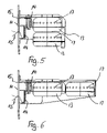
FIG. 5 illustrates the top view of FIG. 3 with two gas generators, and
FIG. 6 illustrates the top view of FIG. 5 with an alternate arrangement of two gas generators.
DETAILED DESCRIPTION OF THE INVENTION
As is evident in FIG. 1 from the top view of the instrument panel 10, including the airbag module with an opening flap 11 provided in the instrument panel. A module casing 12 having a disk-shaped gas generator 13 is connected behind the opening flap 11 in such a manner that the narrow side of the disk-shaped generator 13 is arranged on-edge to the plane of the instrument panel 10, at a right angle in the generator 13 (and its central axis 19) is aligned generally parallel to the plane of the instrument panel 10. Gas generator 13 is of a type having its height or thickness (measured along axis 19) substantially less than its diameter.
As is evident in FIG. 2, a deflector 14, which in the illustrated exemplary embodiment is fastened by fastening plugs 16 feeding through the module casing 12, is arranged in the interior of the module casing 12 in addition to the gas generator 13. On its edges that are directed to the opening flap 11 of the instrument panel 10, the deflector 14 surrounds an airbag 15, which has already unfolded out of the module casing 12 in the exemplary embodiment depicted in FIG. 2. The airbag 15 is connected to the modular casing 12 and deflector 14 by fastening plugs 16 and partially surrounds the deflector 14. A subsection 18 of the deflector 14 partially covers a portion of the perimeter of the gas generator 13 in the central area in such a manner that the radially flowing gas cannot directly act upon the airbag 15 folded in this area but is diverted.
As is evident in FIG. 3, the disk-shaped gas generator 13 includes gas-discharge openings 17 on its outer perimeter through which the gas is released when the gas generator is triggered. This representation is further explained by FIG. 4.
The characteristics of the object of these documents, which are disclosed in the present description, the claims, the abstract and the drawing, may be essential to the realization of the invention in its various embodiments either individually or in any combination.
While the above description constitutes the preferred embodiment of the present invention, it will be appreciated that the invention is susceptible to modification, variation and change without departing from the proper scope and fair meaning of the accompanying claims.

Claims (7)

1. An airbag module for a motor vehicle for mounting behind an instrument panel and deployment through an airbag cover in the instrument panel comprising:
a module casing,
a disk-shaped gas generator mounted within the module casing having gas-discharge openings located on a perimeter of the gas generator, the gas-discharge openings defining a plane,
a deflector that at least partially surrounds the gas-discharge openings,
an airbag that is folded into the module casing, the plane of the disk-shaped gas generator being arranged on-edge substantially perpendicular to the airbag cover in the instrument panel, with the folded airbag arranged at least partially between the perimeter of the gas generator and the airbag cover.
2. An airbag module according to claim 1 wherein the deflector at least partially surrounds the perimeter of the disk-shaped gas generator in the area between the airbag cover and the gas generator in order to guide a gas flow escaping from the gas-discharge openings into the airbag.
3. An airbag module according to claim 1 wherein a subsection of the deflector covers the gas-discharge openings directed toward the airbag cover.
4. An airbag module according to claim 1 wherein two gas generators are arranged within the modular casing.
5. An airbag module according to claim 4 wherein both gas generators are arranged side-by-side relative to the instrument panel.
6. An airbag module according to claim 4 wherein both gas generators are arranged one behind the other relative to the instrument panel.
7. An airbag module according to claim 1 wherein the disk-shaped generator defines a central axis which is substantially parallel with the surface of the airbag cover.
US10/826,012 2003-04-16 2004-04-16 Passenger side airbag module Expired - Fee Related US7159900B2 (en)

Applications Claiming Priority (2)

Application Number Priority Date Filing Date Title
DE10317833A DE10317833B4 (en) 2003-04-16 2003-04-16 Passenger airbag with a built-in pot gas generator
DE10317833.3 2003-04-16

Publications (2)

Publication Number Publication Date
US20040245754A1 US20040245754A1 (en) 2004-12-09
US7159900B2 true US7159900B2 (en) 2007-01-09

Family

ID=33154284

Family Applications (1)

Application Number Title Priority Date Filing Date
US10/826,012 Expired - Fee Related US7159900B2 (en) 2003-04-16 2004-04-16 Passenger side airbag module

Country Status (3)

Country Link
US (1) US7159900B2 (en)
JP (1) JP4482869B2 (en)
DE (1) DE10317833B4 (en)

Families Citing this family (1)

* Cited by examiner, † Cited by third party
Publication number Priority date Publication date Assignee Title
DE202004020096U1 (en) 2004-12-22 2005-03-17 Takata Petri Ag Airbag module especially for a passenger or a knee region has gas generator and airbag arranged one behind the other in a module housing

Citations (19)

* Cited by examiner, † Cited by third party
Publication number Priority date Publication date Assignee Title
US5234229A (en) 1992-02-25 1993-08-10 General Motors Corporation Pressure limited restraint system
US5362096A (en) * 1992-03-05 1994-11-08 Takata Corporation Module cover mounting structure for an air bag device for a passenger
US5547215A (en) * 1994-04-04 1996-08-20 Nippondenso Co., Ltd. Airbag system
US5556129A (en) * 1995-05-16 1996-09-17 Hoover Universal Vehicle seat back with a head side impact air bag
US5676395A (en) 1992-12-18 1997-10-14 Kabushiki Kaisha Tokai-Rika-Denki Seishakusho Tethered air bag
US5927748A (en) * 1997-06-26 1999-07-27 O'driscoll; Peter Multi-stage inflatable bag for vehicular safety systems
US6082765A (en) 1998-11-10 2000-07-04 Trw Vehicle Safety Systems Inc. Air bag module with fluid venting
US6089600A (en) * 1998-09-24 2000-07-18 General Motors Corporation Integral gas direction device for an air bag
US6106002A (en) * 1998-11-06 2000-08-22 Autoliv Development Ab Air-bag arrangement
US6158765A (en) * 1997-09-05 2000-12-12 Volkswagen Ag Occupant protection device for a motor vehicle
US6213502B1 (en) 1998-11-24 2001-04-10 Delphi Technologies, Inc. Air bag module with variable inflation
US6264233B1 (en) 1999-02-18 2001-07-24 Daimlerchrysler Corporation Vehicle airbag assembly
US6352284B1 (en) * 1998-03-27 2002-03-05 Toyoda Gosei Co., Ltd. Airbag system for front passenger's seat
US6382662B1 (en) 1999-07-15 2002-05-07 Takata Corporation Air bag and air bag device
EP1205362A2 (en) 2000-11-14 2002-05-15 Nihon Plast Co., Ltd. Airbag and folding method thereof
US20020149177A1 (en) 2001-04-11 2002-10-17 Rose Larry D. Vehicle occupant restraint module with disk inflator
US6568708B2 (en) * 1999-12-22 2003-05-27 Trw Occupant Restraint Systems Gmbh & Co. Kg Gas bag module with gas guiding means
US6598903B2 (en) * 2000-08-09 2003-07-29 Takata Corporation Airbag with flow adjustment member and tether
US20050110247A1 (en) * 2003-10-10 2005-05-26 Nihon Plast Co., Ltd. Airbag apparatus

Family Cites Families (2)

* Cited by examiner, † Cited by third party
Publication number Priority date Publication date Assignee Title
US5692768A (en) * 1991-10-21 1997-12-02 Trw Vehicle Safety Systems Inc. Airbag assembly
DE29617421U1 (en) * 1996-10-07 1997-02-13 Trw Repa Gmbh Airbag restraint module

Patent Citations (20)

* Cited by examiner, † Cited by third party
Publication number Priority date Publication date Assignee Title
US5234229A (en) 1992-02-25 1993-08-10 General Motors Corporation Pressure limited restraint system
US5362096A (en) * 1992-03-05 1994-11-08 Takata Corporation Module cover mounting structure for an air bag device for a passenger
US5676395A (en) 1992-12-18 1997-10-14 Kabushiki Kaisha Tokai-Rika-Denki Seishakusho Tethered air bag
US5547215A (en) * 1994-04-04 1996-08-20 Nippondenso Co., Ltd. Airbag system
US5556129A (en) * 1995-05-16 1996-09-17 Hoover Universal Vehicle seat back with a head side impact air bag
US5927748A (en) * 1997-06-26 1999-07-27 O'driscoll; Peter Multi-stage inflatable bag for vehicular safety systems
US6158765A (en) * 1997-09-05 2000-12-12 Volkswagen Ag Occupant protection device for a motor vehicle
US6352284B1 (en) * 1998-03-27 2002-03-05 Toyoda Gosei Co., Ltd. Airbag system for front passenger's seat
US6089600A (en) * 1998-09-24 2000-07-18 General Motors Corporation Integral gas direction device for an air bag
US6106002A (en) * 1998-11-06 2000-08-22 Autoliv Development Ab Air-bag arrangement
US6082765A (en) 1998-11-10 2000-07-04 Trw Vehicle Safety Systems Inc. Air bag module with fluid venting
US6213502B1 (en) 1998-11-24 2001-04-10 Delphi Technologies, Inc. Air bag module with variable inflation
US6264233B1 (en) 1999-02-18 2001-07-24 Daimlerchrysler Corporation Vehicle airbag assembly
US6382662B1 (en) 1999-07-15 2002-05-07 Takata Corporation Air bag and air bag device
US6568708B2 (en) * 1999-12-22 2003-05-27 Trw Occupant Restraint Systems Gmbh & Co. Kg Gas bag module with gas guiding means
US6598903B2 (en) * 2000-08-09 2003-07-29 Takata Corporation Airbag with flow adjustment member and tether
EP1205362A2 (en) 2000-11-14 2002-05-15 Nihon Plast Co., Ltd. Airbag and folding method thereof
US20020149177A1 (en) 2001-04-11 2002-10-17 Rose Larry D. Vehicle occupant restraint module with disk inflator
US6702318B2 (en) * 2001-04-11 2004-03-09 Autoliv Asp, Inc. Vehicle occupant restraint module with disk inflator
US20050110247A1 (en) * 2003-10-10 2005-05-26 Nihon Plast Co., Ltd. Airbag apparatus

Also Published As

Publication number Publication date
JP2005001654A (en) 2005-01-06
DE10317833A1 (en) 2004-11-11
US20040245754A1 (en) 2004-12-09
DE10317833B4 (en) 2007-06-21
JP4482869B2 (en) 2010-06-16

Similar Documents

Publication Publication Date Title
US7578518B2 (en) Occupant protection device
US7950688B2 (en) Airbag module
US7445238B2 (en) Occupant protection apparatus
EP1910135B1 (en) Airbag arranged on the vehicle roof
US5533746A (en) Tethered cover for a panel opening in an air bag inflator system
EP1262379B1 (en) Protection device for automobile seat occupant
US20120161424A1 (en) Airbag device
US20050073134A1 (en) Knee protection airbag device
US20020060447A1 (en) Assembly consisting of a backrest and an airbag module
WO1996030233A1 (en) Air bag module
US5527064A (en) Inflatable air bag system
EP0679556B1 (en) Air bag inflator subassembly for installation onto the dashboard substrate of a motor vehicle
US7552939B2 (en) Airbag apparatus having support member attached to vehicle via easily-deformable brackets at both ends
US7775554B2 (en) Air bag module vent
US6851703B2 (en) Housing for an airbag module
JPH10175500A (en) Air bag module assembly for side collision
US20020149183A1 (en) Airbag module
US5893578A (en) Gas bag module for a vehicle occupant restraining system
US7159900B2 (en) Passenger side airbag module
US6663141B2 (en) Inflatable safety restraint assembly and methods of installing such an inflatable safety restraint assembly
US6971668B2 (en) Vehicle interior lining assembly
US20080007037A1 (en) Airbag module
US6017055A (en) Vehicle occupant protection apparatus
US7331605B2 (en) Airbag module for a motor vehicle
KR102609538B1 (en) driver airbag device

Legal Events

Date Code Title Description
AS Assignment

Owner name: AUTOLIV DEVELOPMENT AB, SWEDEN

Free format text: ASSIGNMENT OF ASSIGNORS INTEREST;ASSIGNORS:REITER, THOMAS;SOMMER, KARL HEINZ;ALBERT, JORG;REEL/FRAME:015659/0068

Effective date: 20040726

FPAY Fee payment

Year of fee payment: 4

FPAY Fee payment

Year of fee payment: 8

FEPP Fee payment procedure

Free format text: PAYOR NUMBER ASSIGNED (ORIGINAL EVENT CODE: ASPN); ENTITY STATUS OF PATENT OWNER: LARGE ENTITY

FEPP Fee payment procedure

Free format text: MAINTENANCE FEE REMINDER MAILED (ORIGINAL EVENT CODE: REM.); ENTITY STATUS OF PATENT OWNER: LARGE ENTITY

LAPS Lapse for failure to pay maintenance fees

Free format text: PATENT EXPIRED FOR FAILURE TO PAY MAINTENANCE FEES (ORIGINAL EVENT CODE: EXP.); ENTITY STATUS OF PATENT OWNER: LARGE ENTITY

STCH Information on status: patent discontinuation

Free format text: PATENT EXPIRED DUE TO NONPAYMENT OF MAINTENANCE FEES UNDER 37 CFR 1.362

FP Lapsed due to failure to pay maintenance fee

Effective date: 20190109