US7162576B2 - Storage system - Google Patents
Storage system Download PDFInfo
- Publication number
- US7162576B2 US7162576B2 US10/847,336 US84733604A US7162576B2 US 7162576 B2 US7162576 B2 US 7162576B2 US 84733604 A US84733604 A US 84733604A US 7162576 B2 US7162576 B2 US 7162576B2
- Authority
- US
- United States
- Prior art keywords
- input
- data
- storage system
- cache
- mpu
- Prior art date
- Legal status (The legal status is an assumption and is not a legal conclusion. Google has not performed a legal analysis and makes no representation as to the accuracy of the status listed.)
- Expired - Fee Related, expires
Links
Images


Classifications
-
- G—PHYSICS
- G06—COMPUTING; CALCULATING OR COUNTING
- G06F—ELECTRIC DIGITAL DATA PROCESSING
- G06F3/00—Input arrangements for transferring data to be processed into a form capable of being handled by the computer; Output arrangements for transferring data from processing unit to output unit, e.g. interface arrangements
- G06F3/06—Digital input from, or digital output to, record carriers, e.g. RAID, emulated record carriers or networked record carriers
- G06F3/0601—Interfaces specially adapted for storage systems
- G06F3/0628—Interfaces specially adapted for storage systems making use of a particular technique
- G06F3/0655—Vertical data movement, i.e. input-output transfer; data movement between one or more hosts and one or more storage devices
- G06F3/0658—Controller construction arrangements
-
- G—PHYSICS
- G06—COMPUTING; CALCULATING OR COUNTING
- G06F—ELECTRIC DIGITAL DATA PROCESSING
- G06F3/00—Input arrangements for transferring data to be processed into a form capable of being handled by the computer; Output arrangements for transferring data from processing unit to output unit, e.g. interface arrangements
- G06F3/06—Digital input from, or digital output to, record carriers, e.g. RAID, emulated record carriers or networked record carriers
- G06F3/0601—Interfaces specially adapted for storage systems
- G06F3/0602—Interfaces specially adapted for storage systems specifically adapted to achieve a particular effect
- G06F3/0604—Improving or facilitating administration, e.g. storage management
- G06F3/0605—Improving or facilitating administration, e.g. storage management by facilitating the interaction with a user or administrator
-
- G—PHYSICS
- G06—COMPUTING; CALCULATING OR COUNTING
- G06F—ELECTRIC DIGITAL DATA PROCESSING
- G06F3/00—Input arrangements for transferring data to be processed into a form capable of being handled by the computer; Output arrangements for transferring data from processing unit to output unit, e.g. interface arrangements
- G06F3/06—Digital input from, or digital output to, record carriers, e.g. RAID, emulated record carriers or networked record carriers
- G06F3/0601—Interfaces specially adapted for storage systems
- G06F3/0602—Interfaces specially adapted for storage systems specifically adapted to achieve a particular effect
- G06F3/061—Improving I/O performance
- G06F3/0613—Improving I/O performance in relation to throughput
-
- G—PHYSICS
- G06—COMPUTING; CALCULATING OR COUNTING
- G06F—ELECTRIC DIGITAL DATA PROCESSING
- G06F3/00—Input arrangements for transferring data to be processed into a form capable of being handled by the computer; Output arrangements for transferring data from processing unit to output unit, e.g. interface arrangements
- G06F3/06—Digital input from, or digital output to, record carriers, e.g. RAID, emulated record carriers or networked record carriers
- G06F3/0601—Interfaces specially adapted for storage systems
- G06F3/0668—Interfaces specially adapted for storage systems adopting a particular infrastructure
- G06F3/0671—In-line storage system
- G06F3/0683—Plurality of storage devices
- G06F3/0689—Disk arrays, e.g. RAID, JBOD
-
- G—PHYSICS
- G06—COMPUTING; CALCULATING OR COUNTING
- G06F—ELECTRIC DIGITAL DATA PROCESSING
- G06F12/00—Accessing, addressing or allocating within memory systems or architectures
- G06F12/02—Addressing or allocation; Relocation
- G06F12/08—Addressing or allocation; Relocation in hierarchically structured memory systems, e.g. virtual memory systems
- G06F12/0802—Addressing of a memory level in which the access to the desired data or data block requires associative addressing means, e.g. caches
- G06F12/0866—Addressing of a memory level in which the access to the desired data or data block requires associative addressing means, e.g. caches for peripheral storage systems, e.g. disk cache
-
- G—PHYSICS
- G06—COMPUTING; CALCULATING OR COUNTING
- G06F—ELECTRIC DIGITAL DATA PROCESSING
- G06F2206/00—Indexing scheme related to dedicated interfaces for computers
- G06F2206/10—Indexing scheme related to storage interfaces for computers, indexing schema related to group G06F3/06
- G06F2206/1008—Graphical user interface [GUI]
Definitions
- the present invention relates to storage system technology; and, in particular, the invention relates to a technique for achieving a high-performance storage system wherein a plurality of processors are incorporated in a controller.
- Storage systems typified by disk array devices, are available. Such systems can manage large quantities of electronic data. Improvement of the performance of such storage systems is sought by increasing the speed of data input/output processing. In order to improve the performance of a storage system, application of the SMP technique described in Japanese Patent Application No. 2003-006174 to a storage system disk controller is also being considered.
- each processor in order to speed up memory access, each processor has its own cache.
- synchronization with the data stored in the cache of each processor is performed every time the data of the shared memory is updated. Therefore, in the system of Laid-open Japanese Patent Application No. 2003-006174, an overhead is generated by the processing used to synchronize the data stored in the caches.
- the present invention is applied to a storage system comprising a disk device and a disk controller that receives requests from a superordinate device and has a plurality of processors that control input/output of data with respect to the aforesaid disk device.
- the aforesaid disk controller comprises a plurality of memories that store the operating program of the storage system, a plurality of superordinate interfaces that control input/output of data between the superordinate devices, and a plurality of subordinate interfaces that control input/output of data between the disk devices.
- the memories, the superordinate interfaces and the subordinate interfaces are respectively dedicated for the exclusive use of each processor; and, the plurality of processors respectively execute the operating program by accessing the memories dedicated for their exclusive use, and they perform input/output processing requested from the superordinate devices by controlling these superordinate interfaces and subordinate interfaces that are dedicated for their exclusive use.
- FIG. 1 is a diagrammatic view showing an example of a storage system according to a first embodiment of the present invention
- FIG. 2 is a view diagrammatically showing an example of allocation of a logical volume
- FIG. 3 is a diagram showing an example of a management terminal and management screen
- FIG. 4 is a diagram showing an example of the structure of a cache according to a first embodiment
- FIG. 5 is a process flow diagram showing an example of communication processing for updating of shared management information performed between MPUs of the first embodiment
- FIG. 6 is a diagrammatic view showing an example of the structure of a storage system according to a second embodiment of the present invention, that is set up in expanded bandwidth mode;
- FIG. 7 is a process flow diagram showing an example of processing to effect change over to expanded bandwidth mode of the storage system 10 of the second embodiment
- FIG. 8 is a diagrammatic view showing an example of a storage system according to a third embodiment of the present invention.
- FIGS. 9( a ) and 9 ( b ) are diagrams showing an example of the structure of a cache of the third embodiment
- FIG. 10 is a diagrammatic view showing the condition in which a storage system according to the third embodiment is constituted by a single IO processing system.
- FIG. 11 is a diagram showing an example of a storage system according to a fourth embodiment of the present invention.
- FIG. 1 is a diagram of a storage system according to a first embodiment of the present invention.
- the storage system 10 comprises controllers 100 and 101 that control a storage system 10 , at least one disk device 2 that stores data transmitted from a host computer (not shown) constituting a superordinate device, and loops (hereinbelow referred to as “back-end loops”) 21 , 22 that perform transfer of data and that are connected with the controllers 100 , 101 and the disk device 2 .
- the storage system 10 may be connected with a management terminal for input of various types of settings from the user (the management terminal will be described below).
- the controller 100 performs input/output processing of data between a host computer and the disk device 2 .
- the controller 100 comprises superordinate IFs 1101 , 1102 , subordinate IFs 1201 , 1202 , a data transfer control section 130 , a cache 140 , MPUs (microprocessing units) 1501 , 1502 and memories 1601 , 1602 .
- MPUs microprocessing units
- the superordinate IFs 1101 , 1102 control input/output of data between the host computer and the controller 100 .
- the subordinate IFs 1201 , 1202 perform input/output control of data between the control 100 and the disk device 2 .
- various types of IF such as a Fibre Channel or SCSI (Small Computer System Interface), SATA (Serial ATA), SAS (Serial Attached SCSI), may be employed for connection between the controllers 100 , 101 and the host computer and for connection between the controllers 100 , 101 and the disk device 2 .
- the disk device side may be referred to as the “back end”.
- the superordinate IFs 1101 , 1102 and the subordinate IFs 1201 , 1202 each have a single port, but this is no more than an example.
- the superordinate IFs 1101 , 1102 and the subordinate IFs 1201 , 1202 may be constructed so as to each have a plurality of ports.
- the memories 1601 ( 1602 ) store various types of information necessary for the control of the storage system 10 , such as microprograms executed by the MPUs 1501 ( 1502 ) (operating program of the storage system), control information and management information.
- the cache 140 stores, for example, data exchanged with the host computer, cache management information that indicates the storage location on the cache 140 of the data exchanged with the host computer, system information of the storage system 10 , and shared management information indicating layout information of the disk device 2 (the structure of the data stored in the cache 140 will be described below).
- the data transfer control section 130 controls transfer of data stored in the cache 140 .
- the MPU 1501 executes a microprogram stored in the memory 1601 and performs IO processing in accordance with IO processing instructions from the host computer.
- the unit whose construction makes possible the data input/output processing (IO processing) that is performed between the host computer and the storage system 10 will be referred to as the IO processing system. It will be assumed that a single IO processing system is controlled by a dedicated MPU.
- the controller 100 comprises two IO processing systems, namely, an IO processing system 0 X that is controlled by the MPU 1501 and an IO processing system 0 Y that is controlled by the MPU 1502 . That is, in this embodiment, the controller 100 comprises plural IO processing systems.
- the MPU 1501 of the IO processing system 0 X employs the superordinate IF 1101 , the subordinate IF 1201 and the memory 1601 as dedicated hardware resources of the MPU 1501 .
- the MPU 1502 of the IO processing system 0 Y employs the superordinate IF 1102 , the subordinate IF 1202 and the memory 1602 as dedicated hardware resources of the MPU 1502 .
- the command information is stored at a designated location in the memory 1601 and an interrupt signal is sent to the MPU 1501 .
- the MPU 1501 On receipt of this interrupt signal, the MPU 1501 references the memory 1601 and analyses the command information. If the instruction from the host computer is, for example, a read instruction, and if the subject data is present in the cache 140 , the MPU 1501 then performs hit read processing. The MPU 1501 stores transfer information indicating the address location of the subject data on the cache 140 in a designated location of the memory 1601 and communicates this transfer information to the superordinate IF 1101 .
- the superordinate IF 1101 gives instructions for data transfer to the data transfer control section 130 in accordance with the transfer information that has thus been communicated thereto.
- the data transfer section 130 that has been given these instructions for data transfer reads the subject data from the designated address in the cache 140 and transfers the data to the host computer through the superordinate IF 1101 .
- the superordinate IF 1101 interrupts the MPU 1501 thereby giving notification of completion of data transfer.
- the MPU 1501 reads the subject data from the disk device 2 through the subordinate IF 1201 and stores the subject data in the cache 140 .
- the subject data that is stored on the cache 140 is transferred into the host computer through the superordinate IF 1101 .
- the MPU 1501 If the MPU 1501 has received a write instruction from the host computer, it stores the write data that is sent from the host computer in the cache 140 through the superordinate IF 1101 and then gives a completion report to the host computer. The subject data is then stored in the disk device 2 from the cache 140 through the subordinate IF 1201 .
- the MPU 1501 receives interrupts from the superordinate IF 1101 or subordinate IF 1201 and performs reading or writing of the memory 1601 .
- the hardware resources (superordinate IF 1101 , subordinate IF 1201 and memory 1601 ) are allocated as dedicated hardware resources of the MPU 1501 . Consequently, in this embodiment, IO processing can be executed without interference from other MPUs. In the IO processing system 0 Y also, interference from other MPUs can be avoided by dedication of the superordinate IF 1102 , the subordinate IF 1202 and the memory 1602 in the same way for exclusive use by the MPU 1502 .
- the controller 101 has the same construction as the controller 100 . Specifically, the controller 101 comprises superordinate IFs 1111 , 1112 , subordinate IFs 1211 , 1212 , a data transfer control section 131 , a cache 141 , MPUs 1511 , 1512 and memories 1611 , 1612 .
- the controller 101 is constituted as the ensemble of two IO processing systems, namely the IO processing system 1 X controlled by the MPU 1511 and the IO processing system 1 Y controlled by the MPU 1512 .
- controller 100 and the controller 101 are constituted by the same number of IO processing systems. It should be noted that they could be constituted by any desired number of IO processing systems, so long as the number of IO processing systems of the controller 100 and the controller 101 is the same.
- identical data is stored in the cache 140 and the cache 141 , as a defense against the situation where there is a fault in one or other of the controllers, namely, controller 100 and controller 101 .
- the data transfer control section 130 of the controller 100 and the data transfer control section 131 of the controller 101 are connected by a dedicated circuit (not shown).
- the controller 100 or the controller 101 respectively write data to their own cache, they also write identical data to the other cache.
- a logical volume will be described. Ordinary disk regions are recognized from the host computer in units of logical volumes (LU: logical unit).
- a RAID (Redundant Array Of Independent Disks) group is formed from a plurality of disk devices 2 and a plurality of logical volumes are defined from the RAID group.
- an MPU that is responsible for IO processing of the defined logical volume is set.
- FIG. 2 is a view diagrammatically showing allocation of logical volumes.
- a RAID group 200 is formed from a plurality of disk devices 2 .
- Logical volumes 201 , 202 and 203 are defined from the RAID group 200 .
- the logical volumes 201 , 202 , 203 are managed by an ID (identification symbol) called a “LUN”.
- LUN an ID (identification symbol) called a “LUN”.
- the controller 100 comprises a port A 1701 and a port B 1702 for connection with a host computer, which not shown.
- the port A 1701 receives input/output of data in respect of the IO processing system 0 X.
- the port B 1702 receives input/output of data in respect of the IO processing system 0 Y.
- the controller 101 comprises a port C 1703 and a port D 1704 for connection with a host computer, which is not shown.
- the port D 1703 receives input/output of data in respect of the IO processing system 1 X.
- the port D 1704 receives input/output of data in respect of the IO processing system 1 Y.
- LUN 5 is allocated to the port A 1701 of the IO processing system 0 X. This indicates that the MPU 1501 of the IO processing system 0 X has the ownership rights of LUN 5 . Consequently, MPU 1501 is responsible for IO processing in respect of LUN 5 .
- LUN 7 is allocated to the port B 1702 of the IO processing system 0 Y. This indicates that the MPU 1502 of the IO processing system 0 Y has the ownership rights of LUN 7 . Consequently, MPU 1502 is responsible for the IO processing in respect of LUN 7 .
- LUN 0 is allocated to the port D 1704 of the IO processing system 1 Y in the same way. This indicates that the MPU 1512 of the IO processing system 1 Y has the ownership rights of LUN 0 . Consequently, MPU 1512 is responsible for IO processing in respect of LUN 0 .
- IO processing in respect of the subject volume can be performed independently by the MPU responsible by determining the MPU that has the ownership rights of the logical volume in this way.
- the logical volumes of different responsible MPUs can be mixed in the same RAID group, as in the example of FIG. 2 .
- the ownership rights of a logical volume in the logical volumes in use can be changed over to another MPU.
- FIG. 3 is a view showing an example of a management terminal and a management screen.
- the management terminal 3 that manages the storage system 10 is connected with the storage system 10 through a network.
- a network There is no particular restriction regarding the network used to connect the management terminal 3 and the storage system 10 , but in the following description, the case where the network is a LAN (local area network) will be assumed.
- the storage system 10 comprises a LAN/IF 12 that controls the exchange of data with the management terminal 3 .
- the management terminal 3 comprises an MPU 32 , a memory 33 and a LAN/IF 34 .
- the LAN/IF 34 controls input/output of data with respect to the storage system 10 .
- the memory 33 stores various types of programs (not shown) that control the management terminal 3 and a management program 31 that effects various types of settings in respect of the storage system 10 .
- the MPU 32 executes the various types of programs stored in the memory 33 .
- the MPU 32 executes a management program 31 that is stored in the memory 33 , and it performs various types of setting processing, such as setting the logical volumes of the storage system 10 and port allocation.
- the management terminal 3 is connected with a display device, which is not shown.
- the MPU 32 of the management terminal 3 executes the management program 31 and displays a management screen (for example a screen 311 ) on the display device.
- the user inputs setting data in respect of the storage system 10 at the management terminal 3 while viewing the management screen. Alternatively, the user confirms the settings of the current state of the storage system 10 while viewing the management screen.
- the management terminal 3 receives an input of various types of setting data from the user and effects various types of settings in respect of the storage system 10 in accordance with the setting data that is thus received.
- the management screen displayed by the terminal device 3 will be described.
- an area 311 a where the set condition of the controller 100 of the storage system 10 is displayed and an area 311 b where the set condition of the controller 101 is displayed.
- CTL 0 of the area 311 a and “CTL 1” of the area 311 b respectively indicate the controllers 100 , 101 .
- “ProtGroupX” and “ProtGroupY” subordinate to “CTL 0” of area 311 a respectively indicate the IO processing system 0 X and the IO processing system 0 Y.
- PortA” and “PortB” respectively indicate port A 1701 and port B 1702 .
- the user can identify the IO processing system as a port group. Also, by effecting display in this way, it can be reported to the user that the two logical volumes LUN 5 and LUN 6 are allocated to the port A 17011 and the two logical volumes LUN 7 and LUN 8 are allocated to the port B 1702 . The user can ascertain which logical volumes can be accessed from each port by viewing the management screen 311 .
- the management terminal 3 accepts alterations, such as addition or deletion of logical volumes.
- the management terminal 3 alters the setting of the storage system 10 in accordance with the content of the alteration that it has received.
- the management terminal 3 alters the management screen 311 in accordance with this alteration. For example, if a new LUN 9 is created and LUN 9 is added to the port A 1701 , LUN 9 will be displayed in addition to LUN 5 and LUN 6 in the column “Logical Units” of “PortA” of the management screen 311 being illustrated.
- FIG. 4 is a view showing an example of the cache structure in this embodiment. It should be noted that data identical with the data stored in the cache 140 is mirrored in the cache 141 of the storage terminal 101 . The structure of the data stored in the cache 141 and the structure of the data stored in the cache 140 are therefore identical.
- the cache 140 is divided into regions 14000 to 14008 in which various types of data are stored.
- the region 14000 stores shared management information that is referenced from both MPUs 1501 and 1502 .
- the common management information stored in the region 14000 includes system information of the storage system 10 , configuration information of the logical volume that is created on the disk device 2 and ownership rights information indicating, for example, which MPU is responsible for the logical volume.
- Both the MPU 1501 and the MPU 1502 can access the cache 140 . Consequently, controller 100 need only have a single copy of the shared management information.
- the shared resources in the storage system 10 are managed in an integrated fashion by a representative MPU (for example the MPU 1501 ) and the shared management information is written to the region 14000 so that it can be referenced by the other MPUs.
- the representative MPU 1501 periodically monitors the back end 21 for insertion or removal of disk devices 2 ; and, if it finds that the condition of the disk devices 2 has been altered, it records the content of the alteration of the disk devices 2 in the subject table of the shared management information of the region 14000 .
- the regions 14001 , 14002 , 14003 and 14004 are regions that store cache management information indicating the data storage information on the cache 140 .
- the regions 14005 , 14006 , 14007 and 14008 are data regions that store the data exchanged with the host computer.
- the regions that store the cache management information and the data regions are set up beforehand on start-up of the storage system 10 .
- regions are allocated on the cache 140 dedicated to exclusive employment by the respective MPUs ( 1501 , 1502 , 1511 and 1512 ).
- the cache management information 14001 and data region 14005 are set up and dedicated for exclusive use by the MPU 1501 .
- the cache management information 14002 and data region 14006 are set up and dedicated for exclusive use by the MPU 1502 .
- the cache management information 14003 and data region 14007 are set up and dedicated for exclusive use by the MPU 1511 .
- the cache management information 14004 and data region 140078 are set up and dedicated for exclusive use by the MPU 1512 .
- the region that stores the cache management information that is employed by each MPU and the data region are paired.
- the data arrangement of the data region 14005 that is employed by the MPU 1501 is managed by the cache management information that is stored in the region 14001 .
- the information regarding arrangement, such as the start address and size on the cache 140 , of the cache management information stored in the regions 14001 , 14002 , 14003 and 14004 and the data stored in the data regions 14005 , 14006 , 14007 and 14008 is managed by common management information stored in the region 14000 .
- each MPU dedicated regions for exclusive use by each MPU are arranged to be set up beforehand in the cache 140 . Consequently, in this embodiment, during normal IO processing, exclusive control of the other MPUs in regard to use of the cache region is unnecessary.
- Each MPU can thus independently implement logical volume IO processing for which it is respectively responsible without needing to be concerned about contention with other MPUs.
- a need is generated to perform updating of the common management information 14000 that is stored in the region 14000 in cases where the system information of the storage system is altered by, for example, an alteration of system parameters, or in cases where the logical volume configuration information is altered by creation of a logical volume or changeover of the ownership rights.
- Such alterations may occur as a result of operations performed by the user at the management terminal 3 or may be performed by the storage system 10 itself due to causes internal to the storage system 10 .
- exclusive control of the MPU that alters the shared management information that is stored in the region 14000 and the other MPUs is necessary.
- hardware-based exclusive control may be performed using an atomic lock of the data transfer control section 130 .
- a table for use in exclusive control may be prepared in a cache region that can be referenced by each MPU.
- Software-based exclusive control may then be performed in which, prior to updating of the shared management information stored in the region 14000 , access to the shared management information of the region 14000 by another MPU during updating is prohibited by setting a flag in the exclusive control table.
- FIG. 5 is a flow diagram showing the flow of communication processing of shared management information updating that is performed between the MPUs in this embodiment. An example will be described in which updating of shared management information is communicated from the MPU 1501 to all of the other MPUs (MPUs 1502 , 1511 , 1512 ).
- the MPU 1501 constituting the source of this communication sets a communication message in a predetermined region for communication purposes on the cache 140 .
- a communication message of identical content to that set in the cache 140 is also reflected to the cache 141 by mirroring of the data.
- the communication message includes the IDs of the communication source MPU and the communication destination MPUs. Also, it is arranged for the MPU 1501 to identify which data (for example a Table) has been updated by storing the ID of the updated data (for example a Table) or the address on the cache 140 of the updated data (for example a Table) in a predetermined region (step 501 ).
- the MPU 1501 designates the communication destination MPs to the data transfer control section 130 and gives instructions to issue a communication.
- all of the other MPUs (MPUs 1502 , 1511 , 1512 ) are designated as communication destinations (step 502 ).
- the data transfer control section 130 issues a communication to the designated MPUs.
- communication to the subject MPU is effected from the data transfer control section 130 through the data transfer control section 131 (step 503 ).
- the MPUs that have received a communication from the data transfer control section 130 (or 131 ) read the predetermined region on the cache 140 or cache 141 and analyze the communication message (step 504 ).
- the MPUs being made aware of the subject updated data (updated Table) by the communication message, copy the subject data (Table) from the cache to memory and the updated content is thereby reflected to the memories 1601 , 1602 of the MPUs (step 505 ).
- the MPU constituting the source of the changeover alters the ownership rights information of the logical volume that is the subject of the shared management information of the region 14000 and the arrangement information of the cache 140 of the subject logical volume, from the MPU constituting the source of the changeover to the MPU constituting the destination of the changeover.
- Implementation of a changeover of ownership rights can thus be achieved by communicating the data storage location that has been altered by the changeover source MPU to the changeover destination MPU and the other MPUs.
- a second embodiment of the present invention will be described.
- a construction for expanding the bandwidth of the back-end loop is added to the construction of the storage system 10 of the first embodiment.
- items which are the same as those described in the case of the first embodiment are given the same reference symbols.
- the storage system 10 is configured such that the bandwidth of the back end can be set in a back-end shared mode (hereinbelow referred to as the “standard mode”) and a back-end non-shared mode (hereinbelow referred to as an “expanded bandwidth mode”).
- a back-end shared mode hereinbelow referred to as the “standard mode”
- a back-end non-shared mode hereinbelow referred to as an “expanded bandwidth mode”.
- the standard mode is a configuration in which disk devices 2 are connected to the back-end loops 21 , 22 .
- the subordinate IFs 1201 , 1202 of the controller 100 are connected to a single back-end loop 21 .
- the subordinate IFs 1211 , 1212 of the controller 101 are connected with a single back-end loop 22 .
- the disk devices 2 are respectively connected with the two loops 21 , 22 . That is, in the “standard mode”, a bandwidth corresponding to a total of two loops is available.
- FIG. 6 is a view showing the configuration of a storage system that is set up in the expanded bandwidth mode.
- the disk devices 2 are classified into a group that is connected with the IO processing system X and a group that is connected with the IO processing system Y.
- the disk devices 2 that are classified in the X system are accommodated in the X system drive cabinet 25 .
- the disk devices 2 that are classified in the Y system are accommodated in the wire system drive cabinet 26 .
- the disk devices 2 that are accommodated in the X system drive cabinet 25 are connected by back-end loops 21 and 22 . Also, the disk devices that are accommodated in the Y system drive cabinet 26 are connected by the back-end loops 23 and 24 .
- the disk devices 2 of the group that is connected with the X system and the disk devices 2 of the group that is connected with the Y system are accommodated in separate drive cabinets, there is no particular restriction to this. So long as the disk devices 2 of the group that is connected with the X system and the disk devices 2 of the group that is connected with the Y system are connected with separate back-end loops in each group, they may be accommodated in the same drive cabinet. Also, the disk devices 2 need not be accommodated in drive cabinets.
- the subordinate IF 1201 of the IO processing system X of the controller 100 is connected with the back-end loop 21 which connects the disk devices 2 that are accommodated in the X system drive cabinet 25 .
- the subordinate IF 1211 of the IO processing system X of the controller 101 is connected with the back-end loop 22 that connects the disk devices 2 that are accommodated in the X system drive cabinet 25 .
- the subordinate IF 1202 of the IO processing system Y of the controller 100 is connected with the back-end loop 23 that connects the disk devices 2 that are accommodated in the Y system drive cabinet 26 .
- the subordinate IF 1212 of the IO processing system Y of the controller 101 is connected with the back-end loop 24 that connects the disk devices 2 that are accommodated in the Y system drive cabinet 26 .
- the back-end loops that are capable of being accessed from the controller 100 are two back-end loops, namely, the back-end loop 21 and the back-end loop 23 .
- the subordinate IF 1201 can access the disk devices 2 that are classified in the X system through the back-end loop 21 .
- the subordinate IF 1202 can access the disk devices 2 that are classified in the Y system through the back-end loop 23 .
- the back-end loops that can be accessed from the controller 101 are two, namely, the back-end loop 22 and the back-end loop 24 .
- the subordinate IF 1211 can access the disk devices 2 that are classified in the X system through the back-end loop 22 .
- the subordinate IF 1212 can access the disk devices 2 that are classified in the Y system through the back-end loop 24 .
- the storage system 10 has a total of four back ends i.e. the loop bandwidth is expanded compared with the “standard mode”.
- a single representative MPU is set, and the representative MPU (for example MPU 1501 ) is arranged to perform management of all of the disk devices 20 provided in the storage system 10 .
- a representative MPU is set for each of the respective IO processing systems (each of the X systems and each of the Y systems). For example, it is arranged that the management of the disk devices 2 that are classified in the X system (in the case of the example of FIG. 6 , the disk device 2 of the drive cabinet 25 ) should be performed by the MPU 1501 and that the management of the disk devices 2 that are classified in the Y system (in the case of the example of FIG. 6 , the disk device 2 of the drive cabinet 26 ) should be performed by the MPU 1502 .
- the IO processing system 0 X that is controlled by the MPU 1501 of the controller 100 and the IO processing system 1 X that is controlled by the MPU 1511 of the controller 101 are arranged to be capable of being accessed by the same disk device 2 .
- the IO processing system 0 Y that is processed by the MPU 1502 of the controller 100 and the IO processing system 1 Y that is processed by the MPU 1512 of the controller 101 are arranged to be capable of being accessed by the same disk device 2 .
- the disk devices 2 that can be accessed from each MPU are each of the disk devices classified in the X system and each of the disk devices 2 classified in the Y system. Consequently, in the second embodiment, the configuration of a RAID group including more than one system is prohibited, and a RAID group can be set up only within the same system.
- the location of the disk devices 2 constituting a RAID group can be freely chosen, so long as these disk devices are within the same system.
- an MPU can only be designated as belonging to a system that can access disk devices 2 constituting the subject logical volume.
- setting is restricted such that only the MPU 1501 or MPU 1511 can have ownership rights.
- access is achieved as follows.
- the MPU 1501 (MPU 1511 ) accesses a logical volume of the Y system by requesting the MPU that has the ownership rights of the subject logical volume to perform IO processing of a disk device 2 through the cache 140 (cache 141 ).
- access from the MPU 1502 or MPU 1512 to a logical volume of the X system group is performed by likewise making a request to the MPU having ownership rights thereto.
- the user disconnects the connection of the subordinate IF 1202 and the back-end loop 21 of the controller 100 (see FIG. 1 ). Likewise, the user disconnects the connection of the subordinate IF 1212 and the back-end loop 22 of the controller 101 (see FIG. 1 ). The user then newly connects the back-end loops 23 , 24 that are connected with the disk devices 2 of the Y system drive cabinet 26 that has been prepared with the subordinate IFs 1202 , 1212 (see FIG. 6 ).
- the user notifies the storage system 10 of an intention to start up in the “expanded bandwidth mode” by operating the management terminal 3 .
- the storage system 10 changes over its own settings to “expanded bandwidth mode”.
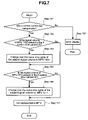
- FIG. 7 is a flow diagram showing the flow of processing involved in changeover of the storage system 10 according to the second embodiment to the expanded bandwidth mode.
- the MPU 1501 was set as the representative MPU in the “standard mode” prior to changeover to the “expanded bandwidth mode”.
- each MPU Ascertains through the subordinate IFs 1201 , 1202 , 1211 and 1212 whether or not the back-end loops 21 , 22 , 23 and 24 are connected normally (step 701 ). In this case, it will be assumed that when the MPU 1501 that has been set as the representative MPU receives instructions to change over to expanded bandwidth mode from the management terminal 3 , it notifies the other MPUs (MPUs 1502 , 1511 and 1512 ) to that effect.
- step 702 if the storage system 10 finds that the back-end loops 21 , 22 , 23 , 24 are not connected normally, processing advances to step 702 ; and, when the back-end loops are connected normally, processing advances to step 703 .
- step 702 the storage system 10 terminates the processing by displaying a connection error at the management terminal 3 .
- the MPU 1501 of the storage system 10 ascertains that there is an error in the connection of the back-end loop 21 for which the MPU 1501 is itself responsible, the MPU 1501 causes a connection error to be displayed on the management terminal 3 .
- the MPU 1501 receives notification of a connection error from another MPU (MPU 1502 , 1511 or 1512 ), it causes a connection error to be displayed on the management terminal 3 .
- step 703 The processing of step 703 will now be described.
- the MPU 1501 references the shared management information 14000 of the cache 140 to ascertain whether or not there is a logical volume to which the MPU 1502 has ownership rights, in the disks 2 that are classified in system X (the disk devices 2 of the X system drive cabinet 25 ). This is because the MPU 1502 cannot access the X system drive cabinet 25 , so that the ownership rights must be changed over to the MPU 1501 . If no logical volume to which the MPU 1502 has ownership rights exists, the MPU 1501 advances to step 705 . However, if a logical volume exists to which the MPU 1502 does have ownership rights, the MPU 1501 advances step 704 .
- step 704 the MPU 1501 changes over the ownership rights of the logical volume to which the MPU 1502 has ownership rights to the MPU 1501 . Specifically, the MPU 1501 rewrites the ownership rights data in the shared management information of the cache 140 .
- step 705 the MPU 1501 checks to ascertain whether or not there exists a logical volume to which the MPU 1512 has ownership rights in the X system drive cabinet 25 . If none exists, the processing advances to step 707 . On the other hand, if a logical volume to which the MPU 1512 does have ownership rights exists, the MPU 1501 advances to step 706 .
- step 706 the MPU 1501 changes over the ownership rights of the logical volume to which the MPU 1512 has ownership rights to the MPU 1511 .
- the MPU 1501 sets the MPU 1501 as the representative MPU that performs management of the X system drive cabinet 25 . Also, the MPU 1501 sets the MPU 1502 as the representative MPU that performs management of the Y system drive cabinet 26 .
- These representative MPUs commence management in “expanded bandwidth mode” and perform periodic back-end monitoring.
- the bandwidth of the back ends can be selected in accordance with the required environment, since, in the second embodiment, it is possible to implement changeover of the back end bandwidth.
- the cache and data transfer control section that are provided by the controller 100 of the storage system 10 of the first embodiment are arranged to be independently provided for each IO processing system.
- items that are the same as those described in the case of the first embodiment are given the same reference symbols.
- FIG. 8 is a diagram of a storage system according to the third embodiment of the present invention.
- the storage system 11 comprises controllers 102 and 103 that control the storage system 10 , at least one or more disk devices 2 that store data from a host computer, which is not shown, and loops (back-end loops) 21 , 22 that perform transfer of data and connect the controllers 102 , 103 and the disk devices 2 .
- the construction of the disk devices 2 and the back-end loops 21 , 22 is the same as that described in connection with the first embodiment described above.
- the MPUs, superordinate IFs, subordinate IFs and memories possessed by the controllers 102 ( 103 ) are the same as in the case of the controllers 100 ( 101 ) of the first embodiment. The following description will concentrate on the items that are different.
- the controller 102 comprises an IO processing system 0 X 1001 and IO processing system 0 Y 1002 .
- the IO processing system 0 X 1001 (IO processing system 0 Y 1002 ) is constructed in modular form and is detachable from the controller 102 .
- the IO processing system 0 X 1001 (IO processing system 0 Y 1002 ) of the controller 102 comprises a superordinate IF 1101 ( 1102 ), a subordinate IF 1201 ( 1202 ), MPU 1501 ( 1502 ), a memory 1601 ( 1602 ), a data transfer control section 1301 ( 1302 ) and a cache 1401 ( 1402 ).
- the IO processing system 0 X 1001 (IO processing system 0 Y 1002 ) does not share the hardware resources in the controller 102 with another IO processing system; and, with the storage system according to the third embodiment, addition and deletion of IO processing functions can therefore easily be performed in IO processing system units.
- the data transfer control section 1301 and the data transfer control section 1302 are connected by a dedicated circuit so that they can access each other's cache.
- the data transfer control section 1301 can perform read/write processing of data on the cache 1402 .
- the data transfer control section 1302 can perform read/write processing of data on the cache 1401 . It should be noted that any desired number of IO processing systems could be employed, so long as they can access the same cache.
- the controller 103 comprises an IO processing system 1 X 10¹¹ and an IO processing system 1 Y 1012 . Also, the controller 103 , like the controller 102 , comprises a superordinate IF, a subordinate IF, a MPU, a memory, a data transfer control section and a cache for each IO processing system.
- identical data is stored in the cache 1401 and the cache 1411 .
- Identical data is also stored in the cache 1402 and in the cache 1412 .
- the data transfer control section 1301 of the controller 102 and the data transfer control section 1311 of the controller 103 are connected by means of a dedicated circuit (not shown). Also, the data transfer control section 1302 of the controller 102 and the data transfer control section 1312 of the controller 103 are connected by means of a dedicated circuit (not shown).
- the data transfer control section 1301 ( 1311 ) when the data transfer control section 1301 ( 1311 ) writes data to the cache 1401 ( 1411 ), the same data is also written to the cache 1411 ( 1401 ). Also, when the data transfer control section 1302 ( 1312 ) writes data to the cache 1402 ( 1412 ), the same data is written to the cache 1412 ( 1402 ).
- the data of the cache 1401 and 1411 can be made to be identical. Also, the data of the cache 1402 and 1412 can be made to be identical.
- FIGS. 9( a ) and 9 ( b ) illustrate the structure of the cache of the third embodiment of the present invention.
- FIG. 9( a ) shows the cache 1401 that stores data relating to the IO processing system 0 X
- FIG. 9( b ) shows the cache 1402 that stores data relating to the IO processing system 0 Y.
- the cache 1401 is divided into regions 14000 , 140001 , 14002 , 14005 , and 14006 .
- the cache 1402 is divided into regions 14000 , 14003 , 14004 , 14007 and 14008 .
- the data stored in the above-described regions corresponds to data stored in the regions 14000 to 14008 shown in FIG. 4 .
- the shared management information that was described with reference to FIG. 4 is stored.
- the regions 14001 , 14002 , 14003 , and 14004 store cache management information indicating the data storage information on the caches 1401 and 1402 .
- the regions 14005 , 14006 , 14007 and 14008 store data that is exchanged with the host computer.
- the shared management information can be accessed from IO processing systems in the same controller in which no fault has occurred, so that the operation can be continued.
- FIG. 10 is a view showing the condition in which the storage system of the third embodiment of the present invention is constituted solely by the X IO processing system.
- the illustrated example shows a condition in which the Y IO processing system of the controllers 102 and 103 has been removed. From the condition illustrated, the user can then expand the system to the functionality of the storage system 11 shown in FIG. 8 by respectively inserting the IO processing system 0 Y 1002 and IO processing system 1 Y 1012 in the controllers 102 and 103 .
- the storage system 11 When the IO processing system 0 Y 1002 and the IO processing system 1 Y 1012 are inserted, the storage system 11 performs processing to effect sharing of the shared management information. Specifically, the storage system 11 performs copying processing in which the shared management information of the regions 14000 of the caches 1401 , 1411 is copied to the regions 14000 of the caches 1402 , 1412 of the inserted IO processing system 0 Y 1002 and IO processing system 1 Y 1012 .
- the MPU 1502 ( 1512 ) of the inserted IO processing system 0 Y 1002 ( 1012 ) then initiates IO processing by copying the necessary information from the shared management information of the region 14000 to the memory 1602 ( 1612 ).
- FIG. 11 is a diagram of a storage system according to the fourth embodiment of the present invention.
- the controllers 102 , 103 that are illustrated here have the same construction as those described with reference to FIG. 8 above.
- the construction of the X system drive cabinet 25 and Y system drive cabinet 26 are the same as the constructions described with reference to FIG. 6 above.
- the subordinate IF 1201 of the X system of the IO processing system of the controller 102 is connected with the back-end loop 21 that connects a disk device 2 that is accommodated in the X system drive cabinet 25 .
- the subordinate IF 1211 of the X system of the IO processing system of the controller 103 is connected with the back-end loop 22 that connects a disk device 2 that is accommodated in the X system drive cabinet 25 .
- the subordinate IF 1202 of the Y system of the IO processing system of the controller 102 is connected with the back-end loop 23 that connects a disk device 2 that is accommodated in the Y system drive cabinet 26 .
- the subordinate IF 1212 of the Y system of the IO processing system of the controller 103 is connected with the back-end loop 24 that connects a disk device 2 that is accommodated in the Y system drive cabinet 26 .
- a representative MPU is set for each respective IO processing system.
- the MPU 1501 is set to implement management in respect of disk devices 2 in the X system drive cabinet 25 .
- the MPU 1502 is set to implement management in respect of disk devices 2 in the Y system drive cabinet 26 .
- changeover from the “standard mode” to the “expanded bandwidth mode” of the fourth embodiment can be effected by the same method as that employed in the case of the second embodiment described above. Also, in the fourth embodiment, it is possible to expand the configuration of the “single IO processing system” of the third embodiment shown in FIG. 10 to change over to the expanded “expanded bandwidth mode”. Also, if the structure is constituted as in the fourth embodiment, the user can also set this to a structure, for example, as shown in FIG. 8 , FIG. 10 or FIG. 11 .
- expansion can be effected in IO processing system units, so that the ability to upgrade the performance of the storage system can be increased.
- the present invention is not restricted to the embodiments described above and could be modified in various ways within the scope of the gist of the present invention.
- the controllers of the storage system were duplicated, there is no particular restriction to this.
- a storage system could be employed that is provided with only a single controller.
Abstract
Description
Claims (7)
Applications Claiming Priority (2)
| Application Number | Priority Date | Filing Date | Title |
|---|---|---|---|
| JP2004-082823 | 2004-03-22 | ||
| JP2004082823A JP4451687B2 (en) | 2004-03-22 | 2004-03-22 | Storage system |
Publications (2)
| Publication Number | Publication Date |
|---|---|
| US20050210188A1 US20050210188A1 (en) | 2005-09-22 |
| US7162576B2 true US7162576B2 (en) | 2007-01-09 |
Family
ID=34987693
Family Applications (1)
| Application Number | Title | Priority Date | Filing Date |
|---|---|---|---|
| US10/847,336 Expired - Fee Related US7162576B2 (en) | 2004-03-22 | 2004-05-18 | Storage system |
Country Status (2)
| Country | Link |
|---|---|
| US (1) | US7162576B2 (en) |
| JP (1) | JP4451687B2 (en) |
Cited By (4)
| Publication number | Priority date | Publication date | Assignee | Title |
|---|---|---|---|---|
| US20070005880A1 (en) * | 2005-06-29 | 2007-01-04 | Burroughs John V | Techniques for providing communications in a data storage system using a single IC for both storage device communications and peer-to-peer communications |
| US7810094B1 (en) * | 2005-09-30 | 2010-10-05 | Emc Corporation | Distributed task scheduling for symmetric multiprocessing environments |
| US20110231605A1 (en) * | 2009-10-27 | 2011-09-22 | Hitachi, Ltd. | Storage controller and storage control method for dynamically assigning partial areas of pool area as data storage areas |
| US20130246728A1 (en) * | 2012-03-15 | 2013-09-19 | Fujitsu Limited | Information processing apparatus |
Families Citing this family (12)
| Publication number | Priority date | Publication date | Assignee | Title |
|---|---|---|---|---|
| US7447834B2 (en) * | 2005-06-29 | 2008-11-04 | Emc Corproation | Managing serial attached small computer systems interface communications |
| JP5106913B2 (en) * | 2007-04-23 | 2012-12-26 | 株式会社日立製作所 | Storage system, storage system management method, and computer system |
| JP2009295049A (en) | 2008-06-06 | 2009-12-17 | Hitachi Ltd | Storage system and ownership transfer method |
| JP5183403B2 (en) | 2008-09-30 | 2013-04-17 | 株式会社日立製作所 | Storage system, control program, and storage system control method |
| US9442540B2 (en) * | 2009-08-28 | 2016-09-13 | Advanced Green Computing Machines-Ip, Limited | High density multi node computer with integrated shared resources |
| JP5170055B2 (en) * | 2009-10-09 | 2013-03-27 | 富士通株式会社 | Processing method, storage system, information processing apparatus, and program |
| JP5431550B2 (en) * | 2012-08-31 | 2014-03-05 | 株式会社日立製作所 | Storage system, storage system management method, and computer system |
| JP5699200B2 (en) * | 2013-12-04 | 2015-04-08 | 株式会社日立製作所 | Storage system, storage system management method, and computer system |
| US9286226B1 (en) * | 2014-03-31 | 2016-03-15 | Emc Corporation | Storage processor hardware upgrade in a storage system |
| WO2016121004A1 (en) * | 2015-01-27 | 2016-08-04 | 株式会社日立製作所 | Storage apparatus |
| JP6836536B2 (en) | 2018-03-19 | 2021-03-03 | 株式会社日立製作所 | Storage system and IO processing control method |
| KR20210095761A (en) * | 2020-01-23 | 2021-08-03 | 삼성전자주식회사 | Storage device and storage system performing offloaded tasks from host |
Citations (8)
| Publication number | Priority date | Publication date | Assignee | Title |
|---|---|---|---|---|
| US20020126711A1 (en) * | 1998-01-14 | 2002-09-12 | Robert Robinett | Network distributed remultiplexer for video program bearing transport streams |
| US6505257B2 (en) | 1994-05-13 | 2003-01-07 | Hitachi, Ltd. | Multi-processor system, disk controller using the same and nondisruptive maintenance method thereof |
| JP2003006174A (en) | 2001-04-12 | 2003-01-10 | Internatl Business Mach Corp <Ibm> | Method, apparatus and program to boot numa (non- uniform-memory-access) machine |
| US6542961B1 (en) | 1998-12-22 | 2003-04-01 | Hitachi, Ltd. | Disk storage system including a switch |
| US6662253B1 (en) | 2000-09-13 | 2003-12-09 | Stmicroelectronics, Inc. | Shared peripheral architecture |
| US20040143712A1 (en) * | 2003-01-16 | 2004-07-22 | International Business Machines Corporation | Task synchronization mechanism and method |
| US6842827B2 (en) * | 2002-01-02 | 2005-01-11 | Intel Corporation | Cache coherency arrangement to enhance inbound bandwidth |
| US6941436B2 (en) * | 2002-05-09 | 2005-09-06 | International Business Machines Corporation | Method and apparatus for managing memory blocks in a logical partitioned data processing system |
-
2004
- 2004-03-22 JP JP2004082823A patent/JP4451687B2/en not_active Expired - Fee Related
- 2004-05-18 US US10/847,336 patent/US7162576B2/en not_active Expired - Fee Related
Patent Citations (8)
| Publication number | Priority date | Publication date | Assignee | Title |
|---|---|---|---|---|
| US6505257B2 (en) | 1994-05-13 | 2003-01-07 | Hitachi, Ltd. | Multi-processor system, disk controller using the same and nondisruptive maintenance method thereof |
| US20020126711A1 (en) * | 1998-01-14 | 2002-09-12 | Robert Robinett | Network distributed remultiplexer for video program bearing transport streams |
| US6542961B1 (en) | 1998-12-22 | 2003-04-01 | Hitachi, Ltd. | Disk storage system including a switch |
| US6662253B1 (en) | 2000-09-13 | 2003-12-09 | Stmicroelectronics, Inc. | Shared peripheral architecture |
| JP2003006174A (en) | 2001-04-12 | 2003-01-10 | Internatl Business Mach Corp <Ibm> | Method, apparatus and program to boot numa (non- uniform-memory-access) machine |
| US6842827B2 (en) * | 2002-01-02 | 2005-01-11 | Intel Corporation | Cache coherency arrangement to enhance inbound bandwidth |
| US6941436B2 (en) * | 2002-05-09 | 2005-09-06 | International Business Machines Corporation | Method and apparatus for managing memory blocks in a logical partitioned data processing system |
| US20040143712A1 (en) * | 2003-01-16 | 2004-07-22 | International Business Machines Corporation | Task synchronization mechanism and method |
Cited By (7)
| Publication number | Priority date | Publication date | Assignee | Title |
|---|---|---|---|---|
| US20070005880A1 (en) * | 2005-06-29 | 2007-01-04 | Burroughs John V | Techniques for providing communications in a data storage system using a single IC for both storage device communications and peer-to-peer communications |
| US7447833B2 (en) | 2005-06-29 | 2008-11-04 | Emc Corporation | Techniques for providing communications in a data storage system using a single IC for both storage device communications and peer-to-peer communications |
| US7810094B1 (en) * | 2005-09-30 | 2010-10-05 | Emc Corporation | Distributed task scheduling for symmetric multiprocessing environments |
| US20110231605A1 (en) * | 2009-10-27 | 2011-09-22 | Hitachi, Ltd. | Storage controller and storage control method for dynamically assigning partial areas of pool area as data storage areas |
| US8307171B2 (en) * | 2009-10-27 | 2012-11-06 | Hitachi, Ltd. | Storage controller and storage control method for dynamically assigning partial areas of pool area as data storage areas |
| US20130246728A1 (en) * | 2012-03-15 | 2013-09-19 | Fujitsu Limited | Information processing apparatus |
| US9032174B2 (en) * | 2012-03-15 | 2015-05-12 | Fujitsu Limited | Information processing apparatus for restricting access to memory area of first program from second program |
Also Published As
| Publication number | Publication date |
|---|---|
| JP2005267545A (en) | 2005-09-29 |
| US20050210188A1 (en) | 2005-09-22 |
| JP4451687B2 (en) | 2010-04-14 |
Similar Documents
| Publication | Publication Date | Title |
|---|---|---|
| US7162576B2 (en) | Storage system | |
| US6957303B2 (en) | System and managing method for cluster-type storage | |
| US6598174B1 (en) | Method and apparatus for storage unit replacement in non-redundant array | |
| JP3201219B2 (en) | I / O processing system | |
| US7971011B2 (en) | Remote copy method and storage system | |
| US6571354B1 (en) | Method and apparatus for storage unit replacement according to array priority | |
| US8806124B2 (en) | Methods and structure for transferring ownership of a logical volume by transfer of native-format metadata in a clustered storage environment | |
| US6446141B1 (en) | Storage server system including ranking of data source | |
| US7536508B2 (en) | System and method for sharing SATA drives in active-active RAID controller system | |
| US7908513B2 (en) | Method for controlling failover processing for a first channel controller and a second channel controller | |
| US7562249B2 (en) | RAID system, RAID controller and rebuilt/copy back processing method thereof | |
| US20040123068A1 (en) | Computer systems, disk systems, and method for controlling disk cache | |
| JP2007094994A (en) | Raid system, and its rebuild/copy back processing method | |
| EP1840745A1 (en) | Disk array device and control method therefor | |
| JP2005301590A (en) | Storage system and data copying method | |
| JP2007086972A (en) | Storage system, duplex control method, and program | |
| US7401196B2 (en) | Storage system and storage control method for access exclusion control of each storage area unit comprising storage area of storage device | |
| US7689765B2 (en) | Control apparatus of storage unit, and method of controlling the control apparatus of storage unit | |
| JP4175083B2 (en) | Storage device management computer and program | |
| US8275958B2 (en) | Storage system with remote copy controllers | |
| JP3195489B2 (en) | External storage control device and bus switching control method | |
| JP2004164047A (en) | Memory system | |
| WO2012035618A1 (en) | Storage system, access control method for storage system, and computer program | |
| US7426658B2 (en) | Data storage system and log data equalization control method for storage control apparatus | |
| US20220308781A1 (en) | Storage system and migration method of storage system |
Legal Events
| Date | Code | Title | Description |
|---|---|---|---|
| AS | Assignment |
Owner name: HITACHI LTD., JAPAN Free format text: ASSIGNMENT OF ASSIGNORS INTEREST;ASSIGNORS:MIZUNO, YOICHI;MATSUNAMI, NAOTO;NISHIMOTO, AKIRA;REEL/FRAME:015648/0168;SIGNING DATES FROM 20040615 TO 20040618 |
|
| FEPP | Fee payment procedure |
Free format text: PAYER NUMBER DE-ASSIGNED (ORIGINAL EVENT CODE: RMPN); ENTITY STATUS OF PATENT OWNER: LARGE ENTITY Free format text: PAYOR NUMBER ASSIGNED (ORIGINAL EVENT CODE: ASPN); ENTITY STATUS OF PATENT OWNER: LARGE ENTITY |
|
| FEPP | Fee payment procedure |
Free format text: PAYER NUMBER DE-ASSIGNED (ORIGINAL EVENT CODE: RMPN); ENTITY STATUS OF PATENT OWNER: LARGE ENTITY |
|
| FEPP | Fee payment procedure |
Free format text: PAYOR NUMBER ASSIGNED (ORIGINAL EVENT CODE: ASPN); ENTITY STATUS OF PATENT OWNER: LARGE ENTITY |
|
| FPAY | Fee payment |
Year of fee payment: 4 |
|
| AS | Assignment |
Owner name: GOOGLE INC., CALIFORNIA Free format text: ASSIGNMENT OF ASSIGNORS INTEREST;ASSIGNOR:HITACHI, LTD.;REEL/FRAME:030555/0554 Effective date: 20121016 |
|
| FPAY | Fee payment |
Year of fee payment: 8 |
|
| AS | Assignment |
Owner name: GOOGLE LLC, CALIFORNIA Free format text: CHANGE OF NAME;ASSIGNOR:GOOGLE INC.;REEL/FRAME:044127/0735 Effective date: 20170929 |
|
| FEPP | Fee payment procedure |
Free format text: MAINTENANCE FEE REMINDER MAILED (ORIGINAL EVENT CODE: REM.); ENTITY STATUS OF PATENT OWNER: LARGE ENTITY |
|
| LAPS | Lapse for failure to pay maintenance fees |
Free format text: PATENT EXPIRED FOR FAILURE TO PAY MAINTENANCE FEES (ORIGINAL EVENT CODE: EXP.); ENTITY STATUS OF PATENT OWNER: LARGE ENTITY |
|
| STCH | Information on status: patent discontinuation |
Free format text: PATENT EXPIRED DUE TO NONPAYMENT OF MAINTENANCE FEES UNDER 37 CFR 1.362 |
|
| FP | Lapsed due to failure to pay maintenance fee |
Effective date: 20190109 |