US7200023B2 - Dual-edged DIMM to support memory expansion - Google Patents
Dual-edged DIMM to support memory expansion Download PDFInfo
- Publication number
- US7200023B2 US7200023B2 US11/127,516 US12751605A US7200023B2 US 7200023 B2 US7200023 B2 US 7200023B2 US 12751605 A US12751605 A US 12751605A US 7200023 B2 US7200023 B2 US 7200023B2
- Authority
- US
- United States
- Prior art keywords
- memory module
- data
- pins
- memory
- dimm
- Prior art date
- Legal status (The legal status is an assumption and is not a legal conclusion. Google has not performed a legal analysis and makes no representation as to the accuracy of the status listed.)
- Expired - Fee Related, expires
Links
- 230000015654 memory Effects 0.000 title claims abstract description 109
- 230000009977 dual effect Effects 0.000 claims abstract description 9
- 230000008878 coupling Effects 0.000 claims description 5
- 238000010168 coupling process Methods 0.000 claims description 5
- 238000005859 coupling reaction Methods 0.000 claims description 5
- 238000000034 method Methods 0.000 abstract description 4
- 230000008901 benefit Effects 0.000 description 3
- 230000006870 function Effects 0.000 description 3
- 238000004891 communication Methods 0.000 description 2
- 238000011144 upstream manufacturing Methods 0.000 description 2
- 230000005540 biological transmission Effects 0.000 description 1
- 238000012937 correction Methods 0.000 description 1
- 125000004122 cyclic group Chemical group 0.000 description 1
- 238000013500 data storage Methods 0.000 description 1
- 230000005055 memory storage Effects 0.000 description 1
- 230000003287 optical effect Effects 0.000 description 1
- 238000012545 processing Methods 0.000 description 1
- 230000004044 response Effects 0.000 description 1
Images


Classifications
-
- G—PHYSICS
- G11—INFORMATION STORAGE
- G11C—STATIC STORES
- G11C5/00—Details of stores covered by group G11C11/00
- G11C5/02—Disposition of storage elements, e.g. in the form of a matrix array
- G11C5/04—Supports for storage elements, e.g. memory modules; Mounting or fixing of storage elements on such supports
Definitions
- the present invention relates in general to the field of computers, and in particular to memory devices. Still more particularly, the present invention relates to a method and system for expanding memory using a novel memory module that has connector pins on its opposite edges.
- Server blade 102 is populated with, inter alia, a Central Processing Unit (CPU) 104 , which is often a cluster of multiple processors. Data is supplied to CPU 104 by a memory controller 106 , which is coupled to CPU 104 via a Northbridge chipset 105 . (Consequently, data that is being sent to CPU 104 is called “northbound,” while data traveling away from CPU 104 is called “southbound.”) While CPU 104 , chipset 105 , and memory controller 106 are depicted as separate components, oftentimes their function is integrated together into one or two chips.
- CPU Central Processing Unit
- chipset 105 chipset 105
- memory controller 106 are depicted as separate components, oftentimes their function is integrated together into one or two chips.
- Coupled to memory controller 106 are multiple data channels (buses), including the depicted Channels 1 – 4 which are respectively connected to memory sockets 108 a–d .
- memory controller 106 can use only two channels, such that Channel 1 is coupled to and supports memory sockets 108 a–b , Channel 2 is coupled to and supports memory sockets 108 c–d , and there are no Channels 3 – 4 .
- server blades 102 a–d are utilized within a blade server chassis 110 .
- Server blades 102 a–d are connected to a midplane 112 (a backplane positioned in a center portion of the blade server chassis 110 ) via respective board slots 114 a–d .
- the memory sockets 108 are configured to orient memory modules 116 at an angle, in order to provide adequate clearance between boards that make up the server blades 102 .
- FIG. 1 c A typical memory module 116 is shown in FIG. 1 c , which shows a Dual In-line Memory Module (DIMM) 118 having multiple Dynamic Random Access Memories (DRAMs) 120 .
- DIMM 118 electrically couples with memory sockets 108 via single-edge pins 122 , which are all on one edge of DIMM 118 .
- DIMM 118 is coupled in series with other DIMMs 118 on other memory sockets 108 .
- each DIMM 118 must be able to pass-through data that is to be stored in another DIMM 118 .
- northbound data enters DIMM 118 on a first set of pins
- northbound data exits DIMM 118 on a different second set of pins
- southbound data enters DIMM 118 on a different third set of pins
- southbound data exits DIMM 118 on a different fourth set of pins where the first, second, third and fourth sets of pins are all part of single-edge pins 122 .
- the amount of memory that can be placed on a single server blade 102 is limited by space. That is, there is simply no physical room to add more memory.
- the present invention is thus directed to a method and system for expanding the number of memory modules that can be coupled to a motherboard such as a server blade.
- a stack of multiple Dual In-line Memory Modules is formed using novel double-connector-edge DIMMs, which each have connector pins on their opposite edges.
- the double-connector-edge DIMM is used to couple the motherboard to a memory expansion card that has multiple single-edge pinned DIMMs coupled in a “daisy-chain.”
- DIBM Dual Inline Buffer Module
- FIGS. 1 a–c depict a prior art blade server chassis using standard Dual In-line Memory Modules (DIMMs);
- DIMMs Dual In-line Memory Modules
- FIG. 2 illustrates an inventive DIMM having connector pins on opposite edges of the DIMM
- FIGS. 3 a–b depict a server blade motherboard coupled to a DIMM expansion card using the inventive DIMM shown in FIG. 2 ;
- FIG. 4 illustrates the server blade motherboard coupled to the DIMM expansion card using a combination of the inventive DIMM and cables
- FIG. 5 depicts the server blade motherboard coupled via cables to the DIMM expansion card, which reuses the inventive DIMM's shown on the server blade motherboard in FIG. 4 on the DIMM expansion card;
- FIG. 6 a illustrates the inventive DIMMs stacked and coupled using double-female connectors
- FIG. 6 b depicts the stacked DIMMs shown in FIG. 6 a installed on a server blade motherboard
- FIG. 6 c illustrates the stacked DIMMs shown in FIG. 6 a coupled to a DIMM socket that is coupled to a motherboard via a cable.
- double-connector-edge DIMM 202 On opposite edges of double-connector-edge DIMM 202 are pins 204 a and 204 b .
- pins 204 a and 204 b each number 240 pins, in order to conform to the standard number of pins in a Low Profile (LP) DIMM (having a height of 1.2′′) and a Very Low Profile (VLP) DIMM (having a height of 0.72′′).
- LP Low Profile
- VLP Very Low Profile
- Pins 204 provide electrical inputs for data and related signals as well as power and ground connections.
- double-connector-edge DIMM 202 has multiple Dynamic Random Access Memories (DRAMs) 206 for storing data.
- DRAMs Dynamic Random Access Memories
- double-connector-edge DIMM 202 has a buffer 208 .
- Buffer 208 is a buffer for all data (including but not limited to data to be stored; data addresses; control signals such as Row Address Strobe (RAS) and Column Address Strobe (CAS), write enable, read enable, chip select, clock input, Error Correction Code—ECC check bits, Cyclic Redundancy Check—CRC bits, etc.) coming off a bus (channel).
- Buffer 208 takes data from one of the edge connectors (e.g., pins 204 a ) and sends it on to the other edge connectors (pins 204 b ). Pins 204 a and 204 b are therefore electrically directly isolated from each other by buffer 208 .
- Buffer 208 includes drivers that are able to re-send each received and buffered (temporarily stored) data, thus keeping the data being transmitted free of distortion.
- data sent through daisy-chained double-connector-edge DIMMs 202 is kept error free during long distance transmissions.
- northbound data traveling towards a CPU enters double-connector-edge DIMM 202 through a first subset of pins 204 a , and exits double-connector-edge DIMM 202 through a first subset of pins 204 b .
- southbound data traveling away from a CPU enters double-connector-edge DIMM 202 through a second subset of pins 204 b , and exits double-connector-edge DIMM 202 through a second subset of pins 204 a .
- fewer pins are used for data flow.
- double-connector-edge DIMM 202 has only two sets of pins on each edge for data going in and out of double-connector-edge DIMM 202 . This frees up two sets of pins on each edge, which can be reused for additional power supplies (to power the DIMM) and grounds (used primarily to keep data signals free of distortion), or to be used as redundant data pins using an appropriately modified DIMM connector.
- blade server chassis 110 is shown using double-connector-edge DIMMs 202 as connectors to a DIMM expansion card 302 .
- blade server chassis 110 has server blade motherboards 102 d , 102 c and 102 a as shown above in FIG. 1 b .
- server blade motherboard 102 b has been replaced with DIMM expansion card 302 , which is inserted into board slot 114 b .
- server blade motherboard 102 b may be electrically not connected to board slot 114 b , or server blade motherboard 102 b may be electrically connected just as the other server blade motherboards 102 a–c and d to provide power and data support to DIMM expansion card 302 and any (not shown) components that may populate DIMM expansion card 302 .
- Memory socket 108 a is plugged into (preferably using pins 204 a ) double-connector-edge DIMM 202 a .
- Double-connector-edge DIMM 202 a is plugged into (preferably using pins 204 b ) a DIMM expansion card connector 304 a on DIMM expansion card 302 .
- DIMM expansion card connector 304 a is electrically connected in daisy-chain series to all memory sockets 308 a (as shown in FIG. 3 b ), each of which has plugged in a single-connector-edge DIMM 118 a .
- single-connector-edge DIMMs 118 are preferably LP DIMMs (described above as having a height of 1.2′′).
- memory sockets 108 and 308 are structurally identical, and vary only by which type of DIMM ( 118 or 202 ) is plugged in at any given time.
- DIMM expansion card 302 can be coupled to server blade motherboard 102 a using clips 402 and cables 404 .
- double-connector-edge DIMM 202 a is plugged into memory socket 108 a using pins 204 b
- pins 204 a are plugged into clip 402 a , which is connected to cable 404 a , which provides a same daisy-chain connection to memory sockets 308 a.
- raw connector plug 502 which has a cable 504 going to DIMM expansion card 302 , is plugged directly into a memory socket 108 .
- Raw connector plug 502 has no memory (DRAMs), and thus is a “raw” (unpopulated) device.
- DRAMs memory
- raw connector plug 502 while having no DRAMs, does have a driver buffer (not shown) such as buffer 208 described above, thus allowing data to be passed through and driven “cleanly.” As shown in FIG.
- exemplary cable 504 a ultimately provides coupling to all of the daisy chained memory sockets 302 a on DIMM expansion card 302 .
- double-connector-edge DIMMs 202 a–d which were coupled to server blade motherboard 102 a in FIG. 4 , have now been moved up to DIMM expansion card 302 , wherein they provide memory storage as well as buffered data communication to “upstream” DIMMs.
- FIG. 5 shows DIMMs 202 a–b respectively coupled to DIMMS 202 c–d
- DIMMs 202 a–b may be single-connector-edge DIMMs 118 .
- a raw connector plug 502 having no DRAMs but having a driver buffer such as buffer 208 can be used to couple motherboard 102 to DIMM expansion card 302 using connections shown in FIGS. 3 a and 4 , replacing DIMMs 202 with raw connector plugs 502 , each raw connector plug 502 preferably having a driver buffer such as buffer 208 .
- double-connector-edge DIMMs 202 can also be stacked as a DIMM stack 600 , as shown in FIG. 6 a .
- double-connector-edge DIMM 202 a can be coupled to double-connector-edge DIMM 202 b with a DIMM coupler 602 a .
- Double-connector-edge DIMM 202 b can be coupled to double-connector-edge DIMM 202 c via DIMM coupler 602 b .
- double-connector-edge DIMM 202 c can then be coupled by DIMM coupler 602 c to a terminal single-connector-edge DIMM 118 , which in a preferred embodiment has a buffer 208 as found in double-connector-edge DIMMs 202 .
- single-connector-edge DIMM 118 can be a double-connector-edge DIMM 202 that has a terminator electrical cap (not shown) that causes the uppermost edge of that double-connector-edge DIMM 202 to re-direct inwardly data in a manner consistent to that of a single-connector-edge DIMM 118 .
- the uppermost DIMM 202 has internal logic that “knows” that there are no “upstream” memories, and thus is able to send data back “downstream.”
- FIG. 6 b a blade server chassis 110 utilizing double-connector-edge DIMMs 202 as shown in FIG. 6 a is shown.
- midplane 112 can support traditional server blade motherboards 102 d and 102 c that respectively support the use of Very Low Profile (VLP) DIMMs 608 and Low Profile (LP) DIMMs 606 .
- VLP Very Low Profile
- LP Low Profile
- board slot 114 b is vacant, leaving additional head room above server blade motherboard 102 a . This affords enough room to stack double-connector-edge DIMMs 202 , as shown in FIG.
- DIMM stacks 600 are clipped together, either permanently or temporarily, to allow ease and freedom to add or remove sections of DIMMs.
- FIG. 6 c shows a preferred embodiment in situations in which space is at a premium, such as in a blade server chassis 110 .
- the DIMM stacks 600 can be “laid down” horizontally, using cables 606 connected to each VLP DIMM socket 604 .
- the cables 606 each coupled to a channel, can be configured such that each DIMM stack 600 has its own cable 606 and thus own channel, or two or more DIMM stacks 600 can use the same cable 606 .
- cables 606 may be a ganged connector that provides the same functionality as the multiple cables 606 .
- the DIMM stacks 600 can be stacked two high (as on server blade 102 c ), four high (as shown on server blade 102 a ), or any other configuration desired.
- each DIMM stack 600 is mechanically clipped to an adjacent DIMM stack 600 using non-conductive clips (not shown) for stability.
- the present invention may alternatively be implemented in a program product.
- Programs defining functions on the present invention can be delivered to a data storage system or a computer system via a variety of signal-bearing media, which include, without limitation, non-writable storage media (e.g., CD-ROM), writable storage media (e.g., a floppy diskette, hard disk drive, read/write CD ROM, optical media), and communication media, such as computer and telephone networks including Ethernet.
- signal-bearing media when carrying or encoding computer readable instructions that direct method functions in the present invention, represent alternative embodiments of the present invention.
- the present invention may be implemented by a system having means in the form of hardware, software, or a combination of software and hardware as described herein or their equivalent.
- the present invention thus provides the benefit over the prior art in allowing memory expansion that requires no additional cost or special connectors on the motherboard, while at the same time giving maximum performance in a minimal space configuration.
- DIMM 202 may be used in any environment where it is desired to expand memory as described.
Abstract
A method and system for expanding the number of memory modules that can be coupled to a motherboard such as a server blade is presented. A stack of multiple Dual In-line Memory Modules (DIMMs) is formed using novel double-connector-edge DIMMs, which each have connector pins on their opposite edges. Alternatively, the double-connector-edge DIMM is used to couple the motherboard to a memory expansion card that has multiple single-edge pinned DIMMs coupled in a “daisy-chain.”
Description
1. Technical Field
The present invention relates in general to the field of computers, and in particular to memory devices. Still more particularly, the present invention relates to a method and system for expanding memory using a novel memory module that has connector pins on its opposite edges.
2. Description of the Related Art
Recent advances in high volume servers have introduced 64-bit processors and operating systems. These systems are capable of directly addressing vast amounts of memory. Therefore, to utilize all of this computing power, users are demanding much more memory capacity.
Some high density servers are so small that they can support only a limited number of memory sockets. For example, consider a server blade 102 shown in FIG. 1 a. Server blade 102 is populated with, inter alia, a Central Processing Unit (CPU) 104, which is often a cluster of multiple processors. Data is supplied to CPU 104 by a memory controller 106, which is coupled to CPU 104 via a Northbridge chipset 105. (Consequently, data that is being sent to CPU 104 is called “northbound,” while data traveling away from CPU 104 is called “southbound.”) While CPU 104, chipset 105, and memory controller 106 are depicted as separate components, oftentimes their function is integrated together into one or two chips.
Coupled to memory controller 106 are multiple data channels (buses), including the depicted Channels 1–4 which are respectively connected to memory sockets 108 a–d. Alternatively, memory controller 106 can use only two channels, such that Channel 1 is coupled to and supports memory sockets 108 a–b, Channel 2 is coupled to and supports memory sockets 108 c–d, and there are no Channels 3–4.
With reference now to FIG. 1 b, multiple server blades 102 a–d are utilized within a blade server chassis 110. Server blades 102 a–d are connected to a midplane 112 (a backplane positioned in a center portion of the blade server chassis 110) via respective board slots 114 a–d. As shown in FIG. 1 b, spacing between server blades 102 is limited. Therefore, the memory sockets 108 are configured to orient memory modules 116 at an angle, in order to provide adequate clearance between boards that make up the server blades 102.
A typical memory module 116 is shown in FIG. 1 c, which shows a Dual In-line Memory Module (DIMM) 118 having multiple Dynamic Random Access Memories (DRAMs) 120. DIMM 118 electrically couples with memory sockets 108 via single-edge pins 122, which are all on one edge of DIMM 118.
Although not shown, typically DIMM 118 is coupled in series with other DIMMs 118 on other memory sockets 108. Thus, each DIMM 118 must be able to pass-through data that is to be stored in another DIMM 118. As will be shown to be significant below, northbound data enters DIMM 118 on a first set of pins, northbound data exits DIMM 118 on a different second set of pins, southbound data enters DIMM 118 on a different third set of pins, and southbound data exits DIMM 118 on a different fourth set of pins, where the first, second, third and fourth sets of pins are all part of single-edge pins 122.
As can be seen in FIGS. 1 a–c, the amount of memory that can be placed on a single server blade 102 is limited by space. That is, there is simply no physical room to add more memory.
In response to the shortcomings of the prior art system described, the present invention is thus directed to a method and system for expanding the number of memory modules that can be coupled to a motherboard such as a server blade. A stack of multiple Dual In-line Memory Modules (DIMMs) is formed using novel double-connector-edge DIMMs, which each have connector pins on their opposite edges. Alternatively, the double-connector-edge DIMM is used to couple the motherboard to a memory expansion card that has multiple single-edge pinned DIMMs coupled in a “daisy-chain.” In another embodiment, a Dual Inline Buffer Module (DIBM), which has a buffer for redrive but no DRAMs, coupled the motherboard to the memory expansion card.
The above, as well as additional purposes, features, and advantages of the present invention will become apparent in the following detailed written description.
The novel features believed characteristic of the invention are set forth in the appended claims. The invention itself, however, as well as a preferred mode of use, further purposes and advantages thereof, will best be understood by reference to the following detailed description of an illustrative embodiment when read in conjunction with the accompanying drawings, where:
With reference now to the FIG. 2 , there is depicted an inventive double-connector-edge Dual In-line Memory Module (DIMM) 202. On opposite edges of double-connector-edge DIMM 202 are pins 204 a and 204 b. Preferably, pins 204 a and 204 b each number 240 pins, in order to conform to the standard number of pins in a Low Profile (LP) DIMM (having a height of 1.2″) and a Very Low Profile (VLP) DIMM (having a height of 0.72″). Pins 204 provide electrical inputs for data and related signals as well as power and ground connections. As shown, double-connector-edge DIMM 202 has multiple Dynamic Random Access Memories (DRAMs) 206 for storing data.
In addition, double-connector-edge DIMM 202 has a buffer 208. Buffer 208, as the name implies, is a buffer for all data (including but not limited to data to be stored; data addresses; control signals such as Row Address Strobe (RAS) and Column Address Strobe (CAS), write enable, read enable, chip select, clock input, Error Correction Code—ECC check bits, Cyclic Redundancy Check—CRC bits, etc.) coming off a bus (channel). Buffer 208 takes data from one of the edge connectors (e.g., pins 204 a) and sends it on to the other edge connectors (pins 204 b). Pins 204 a and 204 b are therefore electrically directly isolated from each other by buffer 208. Buffer 208 includes drivers that are able to re-send each received and buffered (temporarily stored) data, thus keeping the data being transmitted free of distortion. Thus, data sent through daisy-chained double-connector-edge DIMMs 202 is kept error free during long distance transmissions.
Note that northbound data (traveling towards a CPU) enters double-connector-edge DIMM 202 through a first subset of pins 204 a, and exits double-connector-edge DIMM 202 through a first subset of pins 204 b. Similarly, southbound data (traveling away from a CPU) enters double-connector-edge DIMM 202 through a second subset of pins 204 b, and exits double-connector-edge DIMM 202 through a second subset of pins 204 a. Thus, compared to DIMM 118 shown in FIG. 1 c, fewer pins are used for data flow. That is, while DIMM 118 uses four sets of pins for northbound and southbound data going in and out of a single edge of DIMM 118 (as described in FIG. 1's written description), double-connector-edge DIMM 202 has only two sets of pins on each edge for data going in and out of double-connector-edge DIMM 202. This frees up two sets of pins on each edge, which can be reused for additional power supplies (to power the DIMM) and grounds (used primarily to keep data signals free of distortion), or to be used as redundant data pins using an appropriately modified DIMM connector.
With reference now to FIG. 3 a, blade server chassis 110 is shown using double-connector-edge DIMMs 202 as connectors to a DIMM expansion card 302. Note that blade server chassis 110 has server blade motherboards 102 d, 102 c and 102 a as shown above in FIG. 1 b. However, server blade motherboard 102 b has been replaced with DIMM expansion card 302, which is inserted into board slot 114 b. As suggested by the dashed line end, server blade motherboard 102 b may be electrically not connected to board slot 114 b, or server blade motherboard 102 b may be electrically connected just as the other server blade motherboards 102 a–c and d to provide power and data support to DIMM expansion card 302 and any (not shown) components that may populate DIMM expansion card 302.
Referring now to FIG. 4 , DIMM expansion card 302 can be coupled to server blade motherboard 102 a using clips 402 and cables 404. For example, double-connector-edge DIMM 202 a is plugged into memory socket 108 a using pins 204 b, while pins 204 a are plugged into clip 402 a, which is connected to cable 404 a, which provides a same daisy-chain connection to memory sockets 308 a.
With reference now to FIG. 5 , an alternate configuration for coupling DIMM expansion card 302 to server blade motherboard 102 a is depicted. A raw connector plug 502, which has a cable 504 going to DIMM expansion card 302, is plugged directly into a memory socket 108. Raw connector plug 502 has no memory (DRAMs), and thus is a “raw” (unpopulated) device. However, in a preferred embodiment, raw connector plug 502, while having no DRAMs, does have a driver buffer (not shown) such as buffer 208 described above, thus allowing data to be passed through and driven “cleanly.” As shown in FIG. 5 , exemplary cable 504 a ultimately provides coupling to all of the daisy chained memory sockets 302 a on DIMM expansion card 302. Note also that double-connector-edge DIMMs 202 a–d, which were coupled to server blade motherboard 102 a in FIG. 4 , have now been moved up to DIMM expansion card 302, wherein they provide memory storage as well as buffered data communication to “upstream” DIMMs. While FIG. 5 shows DIMMs 202 a–b respectively coupled to DIMMS 202 c–d, alternatively DIMMs 202 a–b may be single-connector-edge DIMMs 118.
Note that a raw connector plug 502 having no DRAMs but having a driver buffer such as buffer 208 can be used to couple motherboard 102 to DIMM expansion card 302 using connections shown in FIGS. 3 a and 4, replacing DIMMs 202 with raw connector plugs 502, each raw connector plug 502 preferably having a driver buffer such as buffer 208.
Besides being useful in connecting a motherboard to a memory expansion board, double-connector-edge DIMMs 202 can also be stacked as a DIMM stack 600, as shown in FIG. 6 a. For example, double-connector-edge DIMM 202 a can be coupled to double-connector-edge DIMM 202 b with a DIMM coupler 602 a. Double-connector-edge DIMM 202 b can be coupled to double-connector-edge DIMM 202 c via DIMM coupler 602 b. As shown in exemplary form, double-connector-edge DIMM 202 c can then be coupled by DIMM coupler 602 c to a terminal single-connector-edge DIMM 118, which in a preferred embodiment has a buffer 208 as found in double-connector-edge DIMMs 202. Alternatively, single-connector-edge DIMM 118 can be a double-connector-edge DIMM 202 that has a terminator electrical cap (not shown) that causes the uppermost edge of that double-connector-edge DIMM 202 to re-direct inwardly data in a manner consistent to that of a single-connector-edge DIMM 118. In another alternate embodiment, the uppermost DIMM 202 has internal logic that “knows” that there are no “upstream” memories, and thus is able to send data back “downstream.”
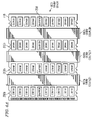
Referring now to FIG. 6 b, a blade server chassis 110 utilizing double-connector-edge DIMMs 202 as shown in FIG. 6 a is shown. As depicted for illustrative purposes only, understand that midplane 112 can support traditional server blade motherboards 102 d and 102 c that respectively support the use of Very Low Profile (VLP) DIMMs 608 and Low Profile (LP) DIMMs 606. As depicted, board slot 114 b is vacant, leaving additional head room above server blade motherboard 102 a. This affords enough room to stack double-connector-edge DIMMs 202, as shown in FIG. 6 a, and then mounting these stacks of DIMMs 202 into standard VLP DIMM sockets 604, as shown in FIG. 6 b. Note that in a preferred embodiment, DIMM stacks 600 are clipped together, either permanently or temporarily, to allow ease and freedom to add or remove sections of DIMMs.
While the configuration shown in FIG. 6 b, is useful in tower computers and other designs that have large amounts of space, FIG. 6 c shows a preferred embodiment in situations in which space is at a premium, such as in a blade server chassis 110. Rather than vertically stack each DIMM stack 600, as shown in FIG. 6 b, the DIMM stacks 600 can be “laid down” horizontally, using cables 606 connected to each VLP DIMM socket 604. The cables 606, each coupled to a channel, can be configured such that each DIMM stack 600 has its own cable 606 and thus own channel, or two or more DIMM stacks 600 can use the same cable 606. Alternatively, cables 606 may be a ganged connector that provides the same functionality as the multiple cables 606. Depending on how much space is available, the DIMM stacks 600 can be stacked two high (as on server blade 102 c), four high (as shown on server blade 102 a), or any other configuration desired. Preferably, each DIMM stack 600 is mechanically clipped to an adjacent DIMM stack 600 using non-conductive clips (not shown) for stability.
It should be understood that at least some aspects of the present invention may alternatively be implemented in a program product. Programs defining functions on the present invention can be delivered to a data storage system or a computer system via a variety of signal-bearing media, which include, without limitation, non-writable storage media (e.g., CD-ROM), writable storage media (e.g., a floppy diskette, hard disk drive, read/write CD ROM, optical media), and communication media, such as computer and telephone networks including Ethernet. It should be understood, therefore in such signal-bearing media when carrying or encoding computer readable instructions that direct method functions in the present invention, represent alternative embodiments of the present invention. Further, it is understood that the present invention may be implemented by a system having means in the form of hardware, software, or a combination of software and hardware as described herein or their equivalent.
The present invention thus provides the benefit over the prior art in allowing memory expansion that requires no additional cost or special connectors on the motherboard, while at the same time giving maximum performance in a minimal space configuration.
While the invention has been particularly shown and described with reference to a preferred embodiment, it will be understood by those skilled in the art that various changes in form and detail may be made therein without departing from the spirit and scope of the invention. For example, while the inventive DIMM 202 has been shown as used in a computer chassis, DIMM 202 may be used in any environment where it is desired to expand memory as described.
Claims (16)
1. A computer system comprising:
a memory module composed of:
a first edge;
an opposite second edge;
a first set of data pins on the first edge;
a second set of data pins on the second edge; and
a data buffer having a driver, wherein the buffer is capable of retransmitting incoming data to the memory module by storing a temporary copy of the incoming data and then transmitting the stored temporary copy of the incoming data away from the memory module, wherein data on the first set of data pins is directly isolated from data on the second set of data pins.
2. The computer system of claim 1 , further comprising:
a memory module connector that electrically connects said first set of data pins on a first memory module to said second, set of data pins on a second memory module.
3. The computer system of claim 1 , wherein the memory module is a Dual In-line Memory Module (DIMM).
4. The computer system of claim 3 , further comprising:
a DIMM expansion card, wherein the DIMM is plugged into a memory socket in the server blade motherboard via the first set of data pins, and wherein the second set of data pins are coupled to the DIMM expansion card.
5. The computer system of claim 3 , further comprising:
at least one DIMM stack, wherein each DIMM stack is constructed by coupling the first set of data pins on a first memory module to the second set of data pins on a second memory module.
6. The computer system of claim 1 , further comprising:
a server blade motherboard;
a raw connector plug coupled to the server blade motherboard;
a memory expansion board on which the memory module is mounted; and
a cable coupling the memory module on the memory expansion board to the raw connector plug on the server blade motherboard.
7. A computer system comprising:
a midplane;
a server blade coupled to a first slot in the midplane;
a memory expansion card coupled to a second slot in the midplane; and
a memory module coupling the server blade to the memory expansion card, wherein the memory module comprises a data buffer that has a driver, wherein the buffer is capable of retransmitting incoming data to the memory module by storing a temporary copy of the incoming data and then transmitting the stored temporary copy of the incoming data away from the memory module, wherein data on a first set of data pins on the memory module is directly isolated from data on a second set of data pins on the memory module.
8. The computer system of claim 7 , further comprising:
a first set of pins on a first edge of the memory module;
a second set of pins on a second edge of the memory module;
a standard memory module socket on the server blade; and
a memory connection socket connected to at least one standard memory socket on the memory expansion card, wherein the first set of pins on the memory module is coupled to the standard memory module socket on the server blade and the second set of pins is coupled to the memory connection socket.
9. The computer system of claim 7 , further comprising:
a first set of pins on a first edge of the memory module;
a second set of pins on an opposite second edge of the memory module;
a standard memory module socket on the server blade; and
a connector clip connected to wiring to at least one standard memory socket on the memory expansion card, wherein the first set of pins is coupled to the standard memory module socket on the server blade and the second set of pins is coupled to the connector clip.
10. The computer system of claim 7 , wherein the memory module is a Dual In-line Memory Module (DIMM).
11. The computer system of claim 7 , wherein the memory expansion card is electrically isolated from the midplane.
12. A memory module comprising:
a first edge;
an opposite second edge;
a first set of data pins on the first edge;
a second set of data pins on the second edge; and
a data buffer having a driver, wherein the buffer is capable of retransmitting incoming data to the memory module by storing a temporary copy of the incoming data and then transmitting the stored temporary copy of the incoming data away from the memory module, wherein data on the first set of data pins is directly isolated from data on the second set of data pins.
13. The memory module of claim 12 , wherein the memory module is a first memory module, and wherein the first memory module is coupled to a second memory module via a memory module connector, wherein the second memory module has a first and second edge with pins as described for the first memory module, and wherein the memory module connector couples the first set of data pins on the first memory module to the second set of data pins on the second memory module.
14. The memory module of claim 12 , wherein the memory module is a Dual In-line Memory Module (DIMM).
15. The memory module of claim 12 , wherein the memory module is mounted on a memory expansion board that is coupled to a motherboard by a raw connector.
16. The memory module of claim 15 , wherein the raw connector has a driver buffer that temporarily stores and then retransmits a clean copy of data between the motherboard and the memory expansion board.
Priority Applications (1)
| Application Number | Priority Date | Filing Date | Title |
|---|---|---|---|
| US11/127,516 US7200023B2 (en) | 2005-05-12 | 2005-05-12 | Dual-edged DIMM to support memory expansion |
Applications Claiming Priority (1)
| Application Number | Priority Date | Filing Date | Title |
|---|---|---|---|
| US11/127,516 US7200023B2 (en) | 2005-05-12 | 2005-05-12 | Dual-edged DIMM to support memory expansion |
Publications (2)
| Publication Number | Publication Date |
|---|---|
| US20060256603A1 US20060256603A1 (en) | 2006-11-16 |
| US7200023B2 true US7200023B2 (en) | 2007-04-03 |
Family
ID=37418944
Family Applications (1)
| Application Number | Title | Priority Date | Filing Date |
|---|---|---|---|
| US11/127,516 Expired - Fee Related US7200023B2 (en) | 2005-05-12 | 2005-05-12 | Dual-edged DIMM to support memory expansion |
Country Status (1)
| Country | Link |
|---|---|
| US (1) | US7200023B2 (en) |
Cited By (33)
| Publication number | Priority date | Publication date | Assignee | Title |
|---|---|---|---|---|
| US7298625B1 (en) * | 2007-01-17 | 2007-11-20 | Inventec Corporation | Expansion structure of memory module slot |
| US20090063923A1 (en) * | 2007-08-31 | 2009-03-05 | Gower Kevin C | System and Method for Performing Error Correction at a Memory Device Level that is Transparent to a Memory Channel |
| US20090063787A1 (en) * | 2007-08-31 | 2009-03-05 | Gower Kevin C | Buffered Memory Module with Multiple Memory Device Data Interface Ports Supporting Double the Memory Capacity |
| US20090063784A1 (en) * | 2007-08-31 | 2009-03-05 | Gower Kevin C | System for Enhancing the Memory Bandwidth Available Through a Memory Module |
| US20090063761A1 (en) * | 2007-08-31 | 2009-03-05 | Gower Kevin C | Buffered Memory Module Supporting Two Independent Memory Channels |
| US20090063731A1 (en) * | 2007-09-05 | 2009-03-05 | Gower Kevin C | Method for Supporting Partial Cache Line Read and Write Operations to a Memory Module to Reduce Read and Write Data Traffic on a Memory Channel |
| US20090063922A1 (en) * | 2007-08-31 | 2009-03-05 | Gower Kevin C | System for Performing Error Correction Operations in a Memory Hub Device of a Memory Module |
| US20090063729A1 (en) * | 2007-08-31 | 2009-03-05 | Gower Kevin C | System for Supporting Partial Cache Line Read Operations to a Memory Module to Reduce Read Data Traffic on a Memory Channel |
| US20090193200A1 (en) * | 2008-01-24 | 2009-07-30 | Brittain Mark A | System to Support a Full Asynchronous Interface within a Memory Hub Device |
| US20090190427A1 (en) * | 2008-01-24 | 2009-07-30 | Brittain Mark A | System to Enable a Memory Hub Device to Manage Thermal Conditions at a Memory Device Level Transparent to a Memory Controller |
| US20090193290A1 (en) * | 2008-01-24 | 2009-07-30 | Arimilli Ravi K | System and Method to Use Cache that is Embedded in a Memory Hub to Replace Failed Memory Cells in a Memory Subsystem |
| US20090193315A1 (en) * | 2008-01-24 | 2009-07-30 | Gower Kevin C | System for a Combined Error Correction Code and Cyclic Redundancy Check Code for a Memory Channel |
| US20090193201A1 (en) * | 2008-01-24 | 2009-07-30 | Brittain Mark A | System to Increase the Overall Bandwidth of a Memory Channel By Allowing the Memory Channel to Operate at a Frequency Independent from a Memory Device Frequency |
| US20090193203A1 (en) * | 2008-01-24 | 2009-07-30 | Brittain Mark A | System to Reduce Latency by Running a Memory Channel Frequency Fully Asynchronous from a Memory Device Frequency |
| US7584308B2 (en) | 2007-08-31 | 2009-09-01 | International Business Machines Corporation | System for supporting partial cache line write operations to a memory module to reduce write data traffic on a memory channel |
| US20100067278A1 (en) * | 2008-09-18 | 2010-03-18 | Hakjune Oh | Mass data storage system with non-volatile memory modules |
| US20110004709A1 (en) * | 2007-09-05 | 2011-01-06 | Gower Kevin C | Method for Enhancing the Memory Bandwidth Available Through a Memory Module |
| US7899983B2 (en) | 2007-08-31 | 2011-03-01 | International Business Machines Corporation | Buffered memory module supporting double the memory device data width in the same physical space as a conventional memory module |
| US7930469B2 (en) | 2008-01-24 | 2011-04-19 | International Business Machines Corporation | System to provide memory system power reduction without reducing overall memory system performance |
| US20110143579A1 (en) * | 2006-08-02 | 2011-06-16 | Chris Karabatsos | Active Dual in Line Memory Module Connector with Re-driven Propagated Signals |
| US8488326B2 (en) | 2010-11-16 | 2013-07-16 | Hewlett-Packard Development Company, L.P. | Memory support structure |
| US8493745B2 (en) | 2011-10-07 | 2013-07-23 | Kingston Technology Corp. | Low-profile motherboard with side-mounted memory modules using a dual-opening edge connector |
| US20140094063A1 (en) * | 2012-09-28 | 2014-04-03 | Gregory M. Daly | System, circuit module, and circuit module connector |
| US9298228B1 (en) | 2015-02-12 | 2016-03-29 | Rambus Inc. | Memory capacity expansion using a memory riser |
| US20160210048A1 (en) * | 2015-01-20 | 2016-07-21 | Ultrata Llc | Object memory data flow triggers |
| US9496633B1 (en) * | 2015-06-22 | 2016-11-15 | Intel Corporation | Memory module adaptor card |
| US20170118839A1 (en) * | 2015-10-23 | 2017-04-27 | International Business Machines Corporation | Printed circuit board with edge soldering for high-density packages and assemblies |
| US20170160956A1 (en) * | 2015-12-02 | 2017-06-08 | International Business Machines Corporation | Concurrent upgrade and backup of non-volatile memory |
| US9916873B2 (en) | 2015-02-12 | 2018-03-13 | Rambus Inc. | Extended capacity memory module with dynamic data buffers |
| US9928884B1 (en) | 2017-05-01 | 2018-03-27 | International Business Machines Corporation | Elastic memory expansion chip architecture |
| US20210315124A1 (en) * | 2020-04-03 | 2021-10-07 | Hewlett Packard Enterprise Development Lp | Cabled module |
| US11394141B2 (en) * | 2020-07-22 | 2022-07-19 | Dell Products L.P. | System and method for stacking compression dual in-line memory module scalability |
| EP3899735A4 (en) * | 2018-12-19 | 2022-09-07 | Micron Technology, Inc. | Module processing resource |
Families Citing this family (14)
| Publication number | Priority date | Publication date | Assignee | Title |
|---|---|---|---|---|
| US8347005B2 (en) * | 2007-07-31 | 2013-01-01 | Hewlett-Packard Development Company, L.P. | Memory controller with multi-protocol interface |
| US8230145B2 (en) * | 2007-07-31 | 2012-07-24 | Hewlett-Packard Development Company, L.P. | Memory expansion blade for multiple architectures |
| US8832344B2 (en) * | 2011-03-30 | 2014-09-09 | Kilseong Ha | Baseboard, extension module, and structure for connecting baseboard and extension module |
| KR20130088911A (en) | 2012-01-31 | 2013-08-09 | 삼성전자주식회사 | Memory module assembly |
| US9841791B2 (en) * | 2013-12-20 | 2017-12-12 | Rambus Inc. | Circuit board assembly configuration |
| WO2016118561A1 (en) * | 2015-01-20 | 2016-07-28 | Ultrata Llc | Object memory fabric performance acceleration |
| US11755202B2 (en) | 2015-01-20 | 2023-09-12 | Ultrata, Llc | Managing meta-data in an object memory fabric |
| US10698628B2 (en) | 2015-06-09 | 2020-06-30 | Ultrata, Llc | Infinite memory fabric hardware implementation with memory |
| US9971542B2 (en) | 2015-06-09 | 2018-05-15 | Ultrata, Llc | Infinite memory fabric streams and APIs |
| US9886210B2 (en) | 2015-06-09 | 2018-02-06 | Ultrata, Llc | Infinite memory fabric hardware implementation with router |
| US10235063B2 (en) | 2015-12-08 | 2019-03-19 | Ultrata, Llc | Memory fabric operations and coherency using fault tolerant objects |
| US10241676B2 (en) | 2015-12-08 | 2019-03-26 | Ultrata, Llc | Memory fabric software implementation |
| EP3387547B1 (en) | 2015-12-08 | 2023-07-05 | Ultrata LLC | Memory fabric software implementation |
| WO2017100288A1 (en) | 2015-12-08 | 2017-06-15 | Ultrata, Llc. | Memory fabric operations and coherency using fault tolerant objects |
Citations (4)
| Publication number | Priority date | Publication date | Assignee | Title |
|---|---|---|---|---|
| US5357621A (en) * | 1990-09-04 | 1994-10-18 | Hewlett-Packard Company | Serial architecture for memory module control |
| US5506788A (en) * | 1994-01-13 | 1996-04-09 | Lsi Logic Corporation | Similarity-extraction force-oriented floor planner |
| US6388886B1 (en) * | 2000-05-08 | 2002-05-14 | Mitsubishi Denki Kabushiki Kaisha | Semiconductor memory module and module system |
| US20030011391A1 (en) | 2001-07-12 | 2003-01-16 | Brunelle Steven J. | Reversed memory module socket, motherboard and test system including same, and method of modifying motherboard |
-
2005
- 2005-05-12 US US11/127,516 patent/US7200023B2/en not_active Expired - Fee Related
Patent Citations (7)
| Publication number | Priority date | Publication date | Assignee | Title |
|---|---|---|---|---|
| US5357621A (en) * | 1990-09-04 | 1994-10-18 | Hewlett-Packard Company | Serial architecture for memory module control |
| US5506788A (en) * | 1994-01-13 | 1996-04-09 | Lsi Logic Corporation | Similarity-extraction force-oriented floor planner |
| US6388886B1 (en) * | 2000-05-08 | 2002-05-14 | Mitsubishi Denki Kabushiki Kaisha | Semiconductor memory module and module system |
| US20030011391A1 (en) | 2001-07-12 | 2003-01-16 | Brunelle Steven J. | Reversed memory module socket, motherboard and test system including same, and method of modifying motherboard |
| US20030107365A1 (en) | 2001-07-12 | 2003-06-12 | Brunelle Steven J. | Reversed memory module socket, motherboard and test system including same, and method of modifying motherboard |
| US20030137862A1 (en) | 2001-07-12 | 2003-07-24 | Brunelle Steven J. | Reversed memory module socket, motherboard and test system including same, and method of modifying motherboard |
| US6721195B2 (en) | 2001-07-12 | 2004-04-13 | Micron Technology, Inc. | Reversed memory module socket and motherboard incorporating same |
Cited By (59)
| Publication number | Priority date | Publication date | Assignee | Title |
|---|---|---|---|---|
| US8040683B2 (en) * | 2006-08-02 | 2011-10-18 | Urenschi Assets Limited Liability Company | Active dual in line memory module connector with re-driven propagated signals |
| US20110143579A1 (en) * | 2006-08-02 | 2011-06-16 | Chris Karabatsos | Active Dual in Line Memory Module Connector with Re-driven Propagated Signals |
| US7298625B1 (en) * | 2007-01-17 | 2007-11-20 | Inventec Corporation | Expansion structure of memory module slot |
| US7584308B2 (en) | 2007-08-31 | 2009-09-01 | International Business Machines Corporation | System for supporting partial cache line write operations to a memory module to reduce write data traffic on a memory channel |
| US8082482B2 (en) | 2007-08-31 | 2011-12-20 | International Business Machines Corporation | System for performing error correction operations in a memory hub device of a memory module |
| US7861014B2 (en) | 2007-08-31 | 2010-12-28 | International Business Machines Corporation | System for supporting partial cache line read operations to a memory module to reduce read data traffic on a memory channel |
| US20090063922A1 (en) * | 2007-08-31 | 2009-03-05 | Gower Kevin C | System for Performing Error Correction Operations in a Memory Hub Device of a Memory Module |
| US20090063729A1 (en) * | 2007-08-31 | 2009-03-05 | Gower Kevin C | System for Supporting Partial Cache Line Read Operations to a Memory Module to Reduce Read Data Traffic on a Memory Channel |
| US20090063761A1 (en) * | 2007-08-31 | 2009-03-05 | Gower Kevin C | Buffered Memory Module Supporting Two Independent Memory Channels |
| US8086936B2 (en) | 2007-08-31 | 2011-12-27 | International Business Machines Corporation | Performing error correction at a memory device level that is transparent to a memory channel |
| US7818497B2 (en) | 2007-08-31 | 2010-10-19 | International Business Machines Corporation | Buffered memory module supporting two independent memory channels |
| US20090063784A1 (en) * | 2007-08-31 | 2009-03-05 | Gower Kevin C | System for Enhancing the Memory Bandwidth Available Through a Memory Module |
| US7840748B2 (en) | 2007-08-31 | 2010-11-23 | International Business Machines Corporation | Buffered memory module with multiple memory device data interface ports supporting double the memory capacity |
| US20090063787A1 (en) * | 2007-08-31 | 2009-03-05 | Gower Kevin C | Buffered Memory Module with Multiple Memory Device Data Interface Ports Supporting Double the Memory Capacity |
| US20090063923A1 (en) * | 2007-08-31 | 2009-03-05 | Gower Kevin C | System and Method for Performing Error Correction at a Memory Device Level that is Transparent to a Memory Channel |
| US7865674B2 (en) | 2007-08-31 | 2011-01-04 | International Business Machines Corporation | System for enhancing the memory bandwidth available through a memory module |
| US7899983B2 (en) | 2007-08-31 | 2011-03-01 | International Business Machines Corporation | Buffered memory module supporting double the memory device data width in the same physical space as a conventional memory module |
| US7558887B2 (en) | 2007-09-05 | 2009-07-07 | International Business Machines Corporation | Method for supporting partial cache line read and write operations to a memory module to reduce read and write data traffic on a memory channel |
| US20110004709A1 (en) * | 2007-09-05 | 2011-01-06 | Gower Kevin C | Method for Enhancing the Memory Bandwidth Available Through a Memory Module |
| US8019919B2 (en) | 2007-09-05 | 2011-09-13 | International Business Machines Corporation | Method for enhancing the memory bandwidth available through a memory module |
| US20090063731A1 (en) * | 2007-09-05 | 2009-03-05 | Gower Kevin C | Method for Supporting Partial Cache Line Read and Write Operations to a Memory Module to Reduce Read and Write Data Traffic on a Memory Channel |
| US7930469B2 (en) | 2008-01-24 | 2011-04-19 | International Business Machines Corporation | System to provide memory system power reduction without reducing overall memory system performance |
| US20090190427A1 (en) * | 2008-01-24 | 2009-07-30 | Brittain Mark A | System to Enable a Memory Hub Device to Manage Thermal Conditions at a Memory Device Level Transparent to a Memory Controller |
| US7770077B2 (en) | 2008-01-24 | 2010-08-03 | International Business Machines Corporation | Using cache that is embedded in a memory hub to replace failed memory cells in a memory subsystem |
| US7925824B2 (en) | 2008-01-24 | 2011-04-12 | International Business Machines Corporation | System to reduce latency by running a memory channel frequency fully asynchronous from a memory device frequency |
| US7925826B2 (en) | 2008-01-24 | 2011-04-12 | International Business Machines Corporation | System to increase the overall bandwidth of a memory channel by allowing the memory channel to operate at a frequency independent from a memory device frequency |
| US7925825B2 (en) | 2008-01-24 | 2011-04-12 | International Business Machines Corporation | System to support a full asynchronous interface within a memory hub device |
| US20090193203A1 (en) * | 2008-01-24 | 2009-07-30 | Brittain Mark A | System to Reduce Latency by Running a Memory Channel Frequency Fully Asynchronous from a Memory Device Frequency |
| US7930470B2 (en) | 2008-01-24 | 2011-04-19 | International Business Machines Corporation | System to enable a memory hub device to manage thermal conditions at a memory device level transparent to a memory controller |
| US20090193201A1 (en) * | 2008-01-24 | 2009-07-30 | Brittain Mark A | System to Increase the Overall Bandwidth of a Memory Channel By Allowing the Memory Channel to Operate at a Frequency Independent from a Memory Device Frequency |
| US20090193315A1 (en) * | 2008-01-24 | 2009-07-30 | Gower Kevin C | System for a Combined Error Correction Code and Cyclic Redundancy Check Code for a Memory Channel |
| US20090193290A1 (en) * | 2008-01-24 | 2009-07-30 | Arimilli Ravi K | System and Method to Use Cache that is Embedded in a Memory Hub to Replace Failed Memory Cells in a Memory Subsystem |
| US8140936B2 (en) | 2008-01-24 | 2012-03-20 | International Business Machines Corporation | System for a combined error correction code and cyclic redundancy check code for a memory channel |
| US20090193200A1 (en) * | 2008-01-24 | 2009-07-30 | Brittain Mark A | System to Support a Full Asynchronous Interface within a Memory Hub Device |
| US20100067278A1 (en) * | 2008-09-18 | 2010-03-18 | Hakjune Oh | Mass data storage system with non-volatile memory modules |
| US10236032B2 (en) | 2008-09-18 | 2019-03-19 | Novachips Canada Inc. | Mass data storage system with non-volatile memory modules |
| US8488326B2 (en) | 2010-11-16 | 2013-07-16 | Hewlett-Packard Development Company, L.P. | Memory support structure |
| US8493745B2 (en) | 2011-10-07 | 2013-07-23 | Kingston Technology Corp. | Low-profile motherboard with side-mounted memory modules using a dual-opening edge connector |
| US20140094063A1 (en) * | 2012-09-28 | 2014-04-03 | Gregory M. Daly | System, circuit module, and circuit module connector |
| US9716327B2 (en) * | 2012-09-28 | 2017-07-25 | Intel Corporation | System, circuit module, and circuit module connector |
| US20160210048A1 (en) * | 2015-01-20 | 2016-07-21 | Ultrata Llc | Object memory data flow triggers |
| US11579774B2 (en) * | 2015-01-20 | 2023-02-14 | Ultrata, Llc | Object memory data flow triggers |
| US9916873B2 (en) | 2015-02-12 | 2018-03-13 | Rambus Inc. | Extended capacity memory module with dynamic data buffers |
| US9298228B1 (en) | 2015-02-12 | 2016-03-29 | Rambus Inc. | Memory capacity expansion using a memory riser |
| US10109324B2 (en) | 2015-02-12 | 2018-10-23 | Rambus Inc. | Extended capacity memory module with dynamic data buffers |
| US9496633B1 (en) * | 2015-06-22 | 2016-11-15 | Intel Corporation | Memory module adaptor card |
| US9716361B2 (en) | 2015-06-22 | 2017-07-25 | Intel Corporation | Memory module adaptor card |
| US9954332B2 (en) | 2015-06-22 | 2018-04-24 | Intel Corporation | Memory module adaptor card |
| US11096290B2 (en) | 2015-10-23 | 2021-08-17 | International Business Machines Corporation | Printed circuit board with edge soldering for high-density packages and assemblies |
| US10098241B2 (en) * | 2015-10-23 | 2018-10-09 | International Business Machines Corporation | Printed circuit board with edge soldering for high-density packages and assemblies |
| US20170118839A1 (en) * | 2015-10-23 | 2017-04-27 | International Business Machines Corporation | Printed circuit board with edge soldering for high-density packages and assemblies |
| US10025508B2 (en) * | 2015-12-02 | 2018-07-17 | International Business Machines Corporation | Concurrent upgrade and backup of non-volatile memory |
| US20170160956A1 (en) * | 2015-12-02 | 2017-06-08 | International Business Machines Corporation | Concurrent upgrade and backup of non-volatile memory |
| US9928884B1 (en) | 2017-05-01 | 2018-03-27 | International Business Machines Corporation | Elastic memory expansion chip architecture |
| EP3899735A4 (en) * | 2018-12-19 | 2022-09-07 | Micron Technology, Inc. | Module processing resource |
| US20210315124A1 (en) * | 2020-04-03 | 2021-10-07 | Hewlett Packard Enterprise Development Lp | Cabled module |
| US11510333B2 (en) * | 2020-04-03 | 2022-11-22 | Hewlett Packard Enterprise Development Lp | Cabled module for adding memory devices to a system |
| US11394141B2 (en) * | 2020-07-22 | 2022-07-19 | Dell Products L.P. | System and method for stacking compression dual in-line memory module scalability |
| US11710915B2 (en) | 2020-07-22 | 2023-07-25 | Dell Products L.P. | System and method for stacking compression dual in-line memory module scalability |
Also Published As
| Publication number | Publication date |
|---|---|
| US20060256603A1 (en) | 2006-11-16 |
Similar Documents
| Publication | Publication Date | Title |
|---|---|---|
| US7200023B2 (en) | Dual-edged DIMM to support memory expansion | |
| US8446781B1 (en) | Multi-rank partial width memory modules | |
| US8208277B2 (en) | Memory modules and memory devices having memory device stacks, and method of forming same | |
| US7793043B2 (en) | Buffered memory architecture | |
| US9535468B2 (en) | Server | |
| EP1581877B1 (en) | Memory subsystem including memory modules having multiple banks | |
| US9298228B1 (en) | Memory capacity expansion using a memory riser | |
| US20060212622A1 (en) | Memory system | |
| US10109324B2 (en) | Extended capacity memory module with dynamic data buffers | |
| US9148974B2 (en) | Serial connection riser cards including parallel connection memory modules | |
| US20090273960A1 (en) | System for providing on-die termination of a control signal bus | |
| JPH06348588A (en) | Single in-line memory module | |
| US20070239906A1 (en) | Input/output agent having multiple secondary ports | |
| JP3806089B2 (en) | Multi-bank memory subsystem with multiple memory modules | |
| JP2019537186A (en) | Expansion platform with additional memory module slots for each CPU socket | |
| KR100761832B1 (en) | Memory system capable of changing the configuration of memory module | |
| US8432707B2 (en) | Card design with fully buffered memory modules and the use of a chip between two consecutive modules | |
| WO2005104324A2 (en) | Folded, fully buffered memory module | |
| TW202226233A (en) | Memory module, main board, and server device | |
| CN117909273A (en) | Computing equipment | |
| JP2008503802A (en) | High speed memory module |
Legal Events
| Date | Code | Title | Description |
|---|---|---|---|
| AS | Assignment |
Owner name: INTERNATIONAL BUSINESS MACHINES CORPORATION, NEW Y Free format text: ASSIGNMENT OF ASSIGNORS INTEREST;ASSIGNOR:FOSTER, JIMMY GRANT;REEL/FRAME:016549/0499 Effective date: 20050408 |
|
| FEPP | Fee payment procedure |
Free format text: PAYOR NUMBER ASSIGNED (ORIGINAL EVENT CODE: ASPN); ENTITY STATUS OF PATENT OWNER: LARGE ENTITY |
|
| REMI | Maintenance fee reminder mailed | ||
| LAPS | Lapse for failure to pay maintenance fees | ||
| STCH | Information on status: patent discontinuation |
Free format text: PATENT EXPIRED DUE TO NONPAYMENT OF MAINTENANCE FEES UNDER 37 CFR 1.362 |
|
| FP | Lapsed due to failure to pay maintenance fee |
Effective date: 20110403 |