US7210893B1 - Flats mail autotrayer system - Google Patents
Flats mail autotrayer system Download PDFInfo
- Publication number
- US7210893B1 US7210893B1 US09/694,653 US69465300A US7210893B1 US 7210893 B1 US7210893 B1 US 7210893B1 US 69465300 A US69465300 A US 69465300A US 7210893 B1 US7210893 B1 US 7210893B1
- Authority
- US
- United States
- Prior art keywords
- stack
- tray
- mailpieces
- accumulator
- large stack
- Prior art date
- Legal status (The legal status is an assumption and is not a legal conclusion. Google has not performed a legal analysis and makes no representation as to the accuracy of the status listed.)
- Expired - Fee Related, expires
Links
Images


Classifications
-
- B—PERFORMING OPERATIONS; TRANSPORTING
- B07—SEPARATING SOLIDS FROM SOLIDS; SORTING
- B07C—POSTAL SORTING; SORTING INDIVIDUAL ARTICLES, OR BULK MATERIAL FIT TO BE SORTED PIECE-MEAL, e.g. BY PICKING
- B07C3/00—Sorting according to destination
- B07C3/008—Means for collecting objects, e.g. containers for sorted mail items
-
- B—PERFORMING OPERATIONS; TRANSPORTING
- B65—CONVEYING; PACKING; STORING; HANDLING THIN OR FILAMENTARY MATERIAL
- B65H—HANDLING THIN OR FILAMENTARY MATERIAL, e.g. SHEETS, WEBS, CABLES
- B65H31/00—Pile receivers
- B65H31/30—Arrangements for removing completed piles
- B65H31/3054—Arrangements for removing completed piles by moving the surface supporting the lowermost article of the pile, e.g. by using belts or rollers
-
- B—PERFORMING OPERATIONS; TRANSPORTING
- B65—CONVEYING; PACKING; STORING; HANDLING THIN OR FILAMENTARY MATERIAL
- B65H—HANDLING THIN OR FILAMENTARY MATERIAL, e.g. SHEETS, WEBS, CABLES
- B65H2301/00—Handling processes for sheets or webs
- B65H2301/40—Type of handling process
- B65H2301/42—Piling, depiling, handling piles
- B65H2301/421—Forming a pile
- B65H2301/4212—Forming a pile of articles substantially horizontal
- B65H2301/42122—Forming a pile of articles substantially horizontal by introducing articles from under the pile
-
- B—PERFORMING OPERATIONS; TRANSPORTING
- B65—CONVEYING; PACKING; STORING; HANDLING THIN OR FILAMENTARY MATERIAL
- B65H—HANDLING THIN OR FILAMENTARY MATERIAL, e.g. SHEETS, WEBS, CABLES
- B65H2301/00—Handling processes for sheets or webs
- B65H2301/40—Type of handling process
- B65H2301/42—Piling, depiling, handling piles
- B65H2301/422—Handling piles, sets or stacks of articles
- B65H2301/4225—Handling piles, sets or stacks of articles in or on special supports
- B65H2301/42254—Boxes; Cassettes; Containers
- B65H2301/422548—Boxes; Cassettes; Containers filling or loading process
-
- B—PERFORMING OPERATIONS; TRANSPORTING
- B65—CONVEYING; PACKING; STORING; HANDLING THIN OR FILAMENTARY MATERIAL
- B65H—HANDLING THIN OR FILAMENTARY MATERIAL, e.g. SHEETS, WEBS, CABLES
- B65H2301/00—Handling processes for sheets or webs
- B65H2301/40—Type of handling process
- B65H2301/44—Moving, forwarding, guiding material
- B65H2301/442—Moving, forwarding, guiding material by acting on edge of handled material
- B65H2301/4423—Moving, forwarding, guiding material by acting on edge of handled material with guide member rotating against the edges of material
-
- B—PERFORMING OPERATIONS; TRANSPORTING
- B65—CONVEYING; PACKING; STORING; HANDLING THIN OR FILAMENTARY MATERIAL
- B65H—HANDLING THIN OR FILAMENTARY MATERIAL, e.g. SHEETS, WEBS, CABLES
- B65H2404/00—Parts for transporting or guiding the handled material
- B65H2404/10—Rollers
- B65H2404/15—Roller assembly, particular roller arrangement
- B65H2404/154—Rollers conveyor
-
- B—PERFORMING OPERATIONS; TRANSPORTING
- B65—CONVEYING; PACKING; STORING; HANDLING THIN OR FILAMENTARY MATERIAL
- B65H—HANDLING THIN OR FILAMENTARY MATERIAL, e.g. SHEETS, WEBS, CABLES
- B65H2701/00—Handled material; Storage means
- B65H2701/10—Handled articles or webs
- B65H2701/19—Specific article or web
- B65H2701/1916—Envelopes and articles of mail
-
- Y—GENERAL TAGGING OF NEW TECHNOLOGICAL DEVELOPMENTS; GENERAL TAGGING OF CROSS-SECTIONAL TECHNOLOGIES SPANNING OVER SEVERAL SECTIONS OF THE IPC; TECHNICAL SUBJECTS COVERED BY FORMER USPC CROSS-REFERENCE ART COLLECTIONS [XRACs] AND DIGESTS
- Y10—TECHNICAL SUBJECTS COVERED BY FORMER USPC
- Y10S—TECHNICAL SUBJECTS COVERED BY FORMER USPC CROSS-REFERENCE ART COLLECTIONS [XRACs] AND DIGESTS
- Y10S209/00—Classifying, separating, and assorting solids
- Y10S209/90—Sorting flat-type mail
Definitions
- the present invention relates to a method and system for high speed accumulation/stacking of mailpieces and postal tray loading of the same.
- the method and system of the present invention comprises an apparatus that combines multiple small stacks of mailpieces into a single large stack of mailpieces in a desired sequence, and then automatically transfers the single large stack into a postal tray.
- the present invention comprises an apparatus that creates an accumulated stack of mail while maintaining the sequence order of the mail in the accumulated stack by selectively placing successive small stacks on the bottom of the accumulated stack, and then selectively transferring the accumulated stack into the postal tray which is then ejected from the apparatus.
- Flats mail, or large format pieces of mail, are typically transported in a standard United States Postal Service flats mail tray.
- Transportation of flats mail is necessary for example from a mailer (companies producing large volumes of mail) to post offices, and from one post office to other post offices.
- the flats mailpieces are sorted and/or otherwise processed prior to being placed into the postal trays in a desired sequence.
- Mail processing machines which process mail and create groups of mail. These mail groups or mail stacks may consist of a single piece or a multitude of pieces. Individual mailpieces range in length from 4 inches to 15.75 inches, in width from 4 inches to 12 inches, and in thickness from 0.007 inches to 1.25 inches. Mail stacks must be transferred into the postal tray on edge, continuously until the tray is filled. Such loading of a mail tray has long been a manual process.
- the present invention fulfills such a need.
- the present invention comprises a method and system for combining multiple small stacks of mailpieces into a single large stack of mailpieces and then transferring the large stack to a standard United States Postal Service flats mail tray, all while maintaining the sequence order of the mail in the accumulated stack, i.e. first pieces processed on top of accumulated stack and last pieces on bottom.
- the present invention is comprised of three primary subsystems: a bridge conveyor, a stack accumulator, and an output tray station.
- the bridge conveyor carries mailpieces from the exit conveyor of a mail processing machine such as a collator (for example, as disclosed in co-pending U.S. patent application entitled “Flats Bundle Collator” concurrently filed herewith, and herein incorporated by reference), to the stack accumulator.
- the stack accumulator combines small stacks of mailpieces into large stacks in a desired sequence.
- the output tray station provides support for an empty tray as the accumulated mail stack is transferred to the tray, and then releases the filled tray in a controlled manner.
- the mail handling surfaces of the system are oriented so that mail stacks are maintained at a twenty degree incline from horizontal throughout the entire autotraying process which encourages the edges of flats mailpieces to uniformly register against a side belt of the bridge conveyor and/or side rollers of the stack accumulator. This configuration assists in controlling the movement of mailpieces and maintaining the sequence order integrity of the accumulated mail stack.
- FIG. 1 is an end view of the present invention.
- FIG. 2 is a top view of the present invention as seen in the direction of line A—A of FIG. 1 .
- FIG. 3 is a top schematic view of the present invention illustrating the mail stack flow.
- FIG. 4 is a side schematic view of the present invention illustrating the mail stack flow.
- FIG. 5 is a top perspective view of the bridge conveyor of the present invention.
- FIG. 6 is a perspective view of the bridge conveyor and the stack accumulator of the present invention.
- FIG. 7 is a front perspective view of the stack accumulator.
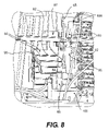
- FIG. 8 is a top perspective view of the stack accumulator.
- FIG. 9 is an enlarged perspective view of the stack accumulator of the present invention.
- FIG. 10 is a front perspective view of the output tray station of the present invention.
- FIG. 11 is an enlarged perspective view of the output tray station of the present invention.
- FIG. 12 is a top perspective view of the bridge conveyor of the present invention in use.
- FIG. 13 is a front perspective view of the stack accumulator of the present invention in use.
- FIG. 14 is a perspective view of the output tray station of the present invention with a tray in position to receive a mail stack.
- FIG. 15 is a perspective view of the output tray station of the present invention with a filled tray in a position to be removed from the present invention.
- FIG. 1 illustrates an end view illustrating the orientation of the present invention 10 at a twenty degree angle to the horizon.
- the bridge conveyor 20 can be seen in FIGS. 2 and 3 as having a plurality of conveyor belts 25 and a side belt 30 which support and guide the individual mail stacks on the bottom and side respectively, and transports the individual mail stacks to the stack accumulator.
- the stack accumulator 50 can be seen in FIGS. 1–3 as having bottom rollers 55 and side rollers 60 which support and guide the individual mail stacks on the bottom and side respectively.
- the fork assembly 80 of the stack accumulator 50 can also be seen as having a fork weldment 81 having fork elements 82 (see FIGS. 2 , 7 and 8 ) shown between rollers 55 .
- a fork actuation air cylinder 83 actuates the fork assembly to move the fork elements in and out of contact with mailpieces; and a fork lift air cylinder 84 raises and lowers the fork assembly, as will be described in more detail below.
- the output tray station 120 can be seen generally in FIGS. 2 and 3 at the end of the stack accumulator 50 .
- the output tray station 120 receives a tray 5 , as will be described in more detail below.
- FIG. 4 shows a schematic view of the present invention 10 .
- the bridge conveyor is positioned proximate the exit conveyor of a mail processing machine, such as a collator.
- a stack height sensor 35 which actuates a second stage of the fork lift cylinder as described in more detail below, is positioned just prior to the entrance of the bridge conveyor 20 .
- a jam detect sensor 40 is positioned at the entrance of the bridge conveyor 20 to determine if a jam has occurred at the entrance of the bridge conveyor.
- the stack accumulator 50 is positioned proximate the end of the bridge conveyor 20 .
- Another jam detect sensor 65 is positioned at the entrance of the stack accumulator 50 to determine if a jam has occurred at the entrance of the stack accumulator.
- a fork cycle trigger sensor 70 is located to trigger the fork cycle as will be described in more detail below.
- the output tray station 120 is positioned at the end of the stack accumulator 50 . As will be described in more detail later, the output tray station receives and supports an empty mail tray for loading of the accumulated stack, and the releases the tray once filled.
- the bridge conveyor 20 is shown consisting of the following significant components.
- Five O-Ring type conveyor belts 25 are provided to contact the bottom mailpiece of an incoming mailpiece stack, and transport the stack to the stack accumulator 20 .
- the O-rings are supported and driven along a conveyor platform 28 by any suitable combination of a drive pulley 26 and idler pulleys 27 , as is known in the art.
- a flat side belt 30 contacts and drives, via any suitable drive means known in the art, the edges of all mailpieces of the incoming stack.
- a stack height sensor 35 (see FIG. 4 ) actuates a second stage of lift fork cylinder 84 when blocked.
- the jam detect sensor 40 is shown positioned at the entrance to the bridge conveyor 20 , which stops the present invention 10 when blocked for an excessive amount of time.
- the stack accumulator 50 is shown consisting of the following significant components.
- a plurality of driven bottom rollers 55 contact the bottom mailpiece in stack and selectively moves the stack.
- a plurality of driven side rollers 60 contact the edges of all of the mailpieces in a stack. These rollers 55 , 60 are slightly spaced apart, enough distance to allow the fort lift fingers or elements 82 to freely pass between.
- a jam detect sensor 65 ( FIG. 8 ) is provided at the entrance of the stack accumulator to stop the present invention, when this sensor is blocked for excessive amount of time.
- a fork cycle trigger sensor 70 ( FIG. 4 ) is positioned towards the end of the stack accumulator to initiate a fork actuation cycle when triggered by the incoming individual stack to the accumulated stack, as described below.
- a stack height limit sensor 75 ( FIG. 9 ) initiates the process of transferring the accumulated stack to the tray when the height of the accumulated stack is great enough to trigger the sensor.
- a fork assembly 80 comprising at least one lift fork element 82 (eight fingers shown), lifts the accumulated stack off of bottom rollers 55 , allowing a subsequent individual stack to be moved thereunder.
- a top roller assembly 85 controls the top of accumulated mail stack and triggers the stack height limit sensor 75 .
- a side guide assembly 90 controls the outside of accumulated mail stack, preventing mailpieces from sliding off of the accumulated stack on the outside.
- a rear flexible guide 95 controls the back of the accumulated mail stack, preventing mailpieces from sliding off of the accumulated stack in back.
- a pusher arm 100 pushes on the rear of the accumulated stack during stack transfer process.
- a stack transfer gate 105 provides a surface for individual mail stacks to register against when they enter the stack accumulator 50 .
- a tray latch assembly 125 secures an empty tray 5 in position for accumulated stack transfer, and automatically releases the filled tray 5 , as described in more detail below.
- a tray detect sensor 130 detects when an empty tray is in position for the accumulated stack transfer process.
- a tray not-in-place indicator lamp 135 (see FIG. 15 ), operatively connected to the tray detect sensor 130 , illuminates when an empty tray is not in position for accumulated stack transfer.
- An empty tray support ledge 140 provides support for the bottom lip 6 (see FIG. 4 ) of the empty tray 5 that is in the accumulated stack transfer position.
- a full tray support platform 145 supports the filled tray at an ergonomically correct height for an operator.
- a plurality of tray guides 150 assist the operator to position empty tray onto the output tray station, and guide filled trays when the latch assembly 125 releases.
- Flexible mail guides 155 and a plurality of idler rollers 160 guide the bottom of accumulated mail stack as it is transferred to tray.
- an emergency stop button 170 is provided which stops the present invention 10 when pressed.
- System operation begins when a mail stack 7 is transferred from the exit conveyor of a mail processing machine to the bridge conveyor 20 of the present invention 10 .
- a mail stack 7 blocks the stack height sensor 35 as it passes from the exit conveyor to the bridge conveyor 20
- the second stage of the lift fork air cylinder 84 is actuated to raise the accumulated stack to provide additional clearance between the accumulated stack and the underside of the lift fork elements 82 .
- This stack height sensor 35 is positioned prior to entrance of the bridge conveyor 20 .
- Mail stacks 7 pass through a jam detect sensor beam 40 as they enter the bridge conveyor 20 . If the beam is blocked for an excessive amount of time, the control system of the present invention 10 declares that a mail jam has occurred and the system is stopped. Mail stacks 7 also pass through a jam detect sensor beam 65 as they exit the bridge conveyor 20 and enter the stack accumulator 50 . If the beam is blocked for an excessive amount of time, the control system of the present invention declares that a mail jam has occurred and the system is stopped.
- Mail stacks 7 are conveyed from the bridge conveyor 20 into the stack accumulator by bottom belts 25 and a side belt 30 .
- the surface speed of the bridge conveyor belts is identical to that of the bottom rollers 55 and side rollers 60 in the stack accumulator 50 .
- Mail stacks 7 are driven into the stack accumulator 50 by rollers 55 and 60 until they stop against the vertical surface of the stack transfer gate 105 .
- the side rollers 60 rotate continuously throughout system operation.
- the bottom rollers 55 are paused when the fork cycle is performed.
- the fork cycle trigger sensor 70 is preferably located approximately three inches prior to the gate 105 .
- the fork cycle consists of the following series of movements.
- the lift fork elements 82 holding the accumulated stack 8 , retract between the rollers 60 until the elements are completely behind the surface of the side rollers 60 .
- the accumulated mail stack drops on top of the incoming mail stack 7 .
- the fork elements 82 next lower to a position where the elements 82 are below the top surface of the bottom rollers 55 .
- the fork elements 82 extend back into the stack accumulator 50 , between and/or under the rollers 55 , and under the accumulated stack 8 . Finally, the fork elements 82 rise to a nominal position above the top surface of the bottom rollers 55 , allowing the subsequent stack 7 to move under the accumulated stack 8 .
- the fork cycle is repeated for each mail stack 7 that enters the accumulator 50 . Again, each time the fork elements 82 are retracted, the accumulated mail stack 8 falls on top of the incoming stack 7 that has just registered against the vertical surface of the gate 105 . When the elements 82 of the fork assembly 80 rise from between the bottom rollers 55 , the accumulated stack 8 is raised off of the bottom rollers 55 so that another incoming stack 7 can enter the accumulator.
- a top roller assembly 85 operatively mounted to a pivot arm 88 rests on top of the accumulated mail stack 8 as the fork cycles are performed.
- the roller 85 moves up and down via pivot arm 88 with the accumulated stack 8 .
- the weight of this roller 85 exerts a pressure to the top of the stack 8 that assists in maintaining stack integrity.
- the top roller pivot arm 88 blocks the stack height limit sensor beam 75 when the accumulated mail stack 8 is resting on the bottom rollers 55 , the stack transfer process is initiated.
- the top roller assembly 85 in conjunction with the stack height limit sensor 75 acts as the maximum stack height gage.
- the stack transfer process consists of the following actions.
- the bottom rollers 55 are actuated, the top roller drive motor 87 is activated, the side guide assembly 90 is retracted, the gate 105 is opened, the pusher arm 100 is actuated, and the tray latch cylinder 126 is actuated.
- the accumulated mail stack 8 is driven on three sides into the mail tray 5 during the stack transfer process by the bottom rollers 55 , side rollers 60 and top roller 85 .
- a roller mounted on the end of the pusher arm 100 stays in contact with the backside of the rear flexible guide 95 .
- the resulting effect of this actuation on the mail stack 8 is similar to that of a wall pushing on the rear of the stack 8 .
- the side guide 90 is retracted, by any suitable means, during the stack transfer process so that the high friction belt strips 92 , which are attached to the guide 90 , do not inhibit the movement of the stack 8 into the mail tray 5 .
- a plastic disc 127 mounted on the end of the cylinder rod is extended towards the tray 5 .
- the disc 127 initially disengages the latch 125 from the tray 5 and then pushes on the tray 5 to ensure that it falls clear of the gate 105 at the appropriate time within the cycle.
- the momentum of the mail stack 8 striking the tray 5 and force of gravity complete the process of lowering the tray 5 to the tray support platform 145 .
- the tray detect sensor 130 When a filled tray 5 is ejected from the empty tray position, the tray detect sensor 130 is unblocked. This condition causes the tray not-in-place lamp 135 to illuminate which alerts the operator that the filled tray 5 must be removed and an empty tray 5 installed. If the tray detect sensor 130 remains unblocked when a stack transfer is initiated, system operation automatically stops.
- All drive means and sensors are operatively connected to suitable controllers, such as programable logic controllers to synchronize operation of all assemblies of the present invention.
- suitable controllers such as programable logic controllers to synchronize operation of all assemblies of the present invention.
- the present invention provides for constant control of each mail stack, accumulated mail stack, and tray to achieve the accumulating/stacking of individual mail stacks into one accumulated mail stack, in the desired sequence, and the transfer of the accumulated mail stack into the tray.
- the height of the accumulated stack that is transferred to the mail tray is preferably approximately 12 inches.
Abstract
Description
Claims (37)
Priority Applications (1)
| Application Number | Priority Date | Filing Date | Title |
|---|---|---|---|
| US09/694,653 US7210893B1 (en) | 2000-10-23 | 2000-10-23 | Flats mail autotrayer system |
Applications Claiming Priority (1)
| Application Number | Priority Date | Filing Date | Title |
|---|---|---|---|
| US09/694,653 US7210893B1 (en) | 2000-10-23 | 2000-10-23 | Flats mail autotrayer system |
Publications (1)
| Publication Number | Publication Date |
|---|---|
| US7210893B1 true US7210893B1 (en) | 2007-05-01 |
Family
ID=37991364
Family Applications (1)
| Application Number | Title | Priority Date | Filing Date |
|---|---|---|---|
| US09/694,653 Expired - Fee Related US7210893B1 (en) | 2000-10-23 | 2000-10-23 | Flats mail autotrayer system |
Country Status (1)
| Country | Link |
|---|---|
| US (1) | US7210893B1 (en) |
Cited By (13)
| Publication number | Priority date | Publication date | Assignee | Title |
|---|---|---|---|---|
| US20080015735A1 (en) * | 2006-07-13 | 2008-01-17 | Pitney Bowes Incorporated | Apparatus and method for positioning objects/mailpieces |
| US20080093273A1 (en) * | 2004-07-21 | 2008-04-24 | Stemmle Denis J | Carrier Delivery Sequence System And Process Adapted For Upstream Insertion Of Exceptional Mail Pieces |
| US20080164185A1 (en) * | 2004-12-07 | 2008-07-10 | Stemmle Denis J | Clamp for Mixed Mail Sorter |
| US20090000996A1 (en) * | 2005-04-07 | 2009-01-01 | Pitney Bowes Inc. | Macro Sorting System and Method |
| US7527261B2 (en) | 2006-07-13 | 2009-05-05 | Lockheed Martin Corporation | Mailpiece container for stacking mixed mail and method for stacking mail therein |
| US20090254212A1 (en) * | 2007-11-08 | 2009-10-08 | Northrop Grumman Systems Corporation | Bulk flats induction method and system |
| US7769765B2 (en) | 2006-07-25 | 2010-08-03 | Lockheed Martin Corporation | Method and system for sorting mail |
| US7820932B2 (en) | 2006-07-13 | 2010-10-26 | Lockheed Martin Corporation | Mail sorter, method, and software product for a two-step and one-pass sorting algorithm |
| US7937184B2 (en) | 2006-10-06 | 2011-05-03 | Lockheed Martin Corporation | Mail sorter system and method for productivity optimization through precision scheduling |
| US7947916B2 (en) | 2006-10-06 | 2011-05-24 | Lockheed Martin Corporation | Mail sorter system and method for moving trays of mail to dispatch in delivery order |
| US8556260B2 (en) | 2006-05-26 | 2013-10-15 | Lockheed Martin Corporation | Method for optimally loading objects into storage/transport containers |
| CN106241392A (en) * | 2016-08-31 | 2016-12-21 | 中冶华天工程技术有限公司 | High speed piling system with precise positioning |
| US10144037B2 (en) * | 2016-02-15 | 2018-12-04 | Toshiba International Corporation | System and method for adjusting contents of an automation tray |
Citations (10)
| Publication number | Priority date | Publication date | Assignee | Title |
|---|---|---|---|---|
| BE628233A (en) * | ||||
| US3055514A (en) * | 1960-07-26 | 1962-09-25 | Lamb Grays Harbor Co Inc | Fork lift type bale stacker |
| US4508483A (en) * | 1982-03-23 | 1985-04-02 | Gottfried J. Weykam | Lifting device for a magazine for empty pallets in an automatic palletizing machine |
| US4655663A (en) * | 1984-11-14 | 1987-04-07 | R.O.M. S.R.L. | Machine for stacking bundles of signatures and like products |
| US5609333A (en) * | 1995-10-05 | 1997-03-11 | Xerox Corporation | Sheet stack height control system |
| US5803704A (en) * | 1994-02-01 | 1998-09-08 | Lockheed Martin Corporation | Apparatus and method for accumulating and transferring one or more stacks of articles |
| US5951238A (en) * | 1997-08-05 | 1999-09-14 | Duecker; Peter | Auto pallet stacking/loading device |
| US6026967A (en) * | 1997-01-30 | 2000-02-22 | Electrocom Automation | Method and apparatus for sorting flat articles |
| US6241099B1 (en) * | 1999-05-12 | 2001-06-05 | Northrop Grumman Corporation | Flats bundle collator |
| US6422806B1 (en) * | 2000-03-28 | 2002-07-23 | Kolinahr Systems, Inc. | Pallet stacker system |
-
2000
- 2000-10-23 US US09/694,653 patent/US7210893B1/en not_active Expired - Fee Related
Patent Citations (10)
| Publication number | Priority date | Publication date | Assignee | Title |
|---|---|---|---|---|
| BE628233A (en) * | ||||
| US3055514A (en) * | 1960-07-26 | 1962-09-25 | Lamb Grays Harbor Co Inc | Fork lift type bale stacker |
| US4508483A (en) * | 1982-03-23 | 1985-04-02 | Gottfried J. Weykam | Lifting device for a magazine for empty pallets in an automatic palletizing machine |
| US4655663A (en) * | 1984-11-14 | 1987-04-07 | R.O.M. S.R.L. | Machine for stacking bundles of signatures and like products |
| US5803704A (en) * | 1994-02-01 | 1998-09-08 | Lockheed Martin Corporation | Apparatus and method for accumulating and transferring one or more stacks of articles |
| US5609333A (en) * | 1995-10-05 | 1997-03-11 | Xerox Corporation | Sheet stack height control system |
| US6026967A (en) * | 1997-01-30 | 2000-02-22 | Electrocom Automation | Method and apparatus for sorting flat articles |
| US5951238A (en) * | 1997-08-05 | 1999-09-14 | Duecker; Peter | Auto pallet stacking/loading device |
| US6241099B1 (en) * | 1999-05-12 | 2001-06-05 | Northrop Grumman Corporation | Flats bundle collator |
| US6422806B1 (en) * | 2000-03-28 | 2002-07-23 | Kolinahr Systems, Inc. | Pallet stacker system |
Cited By (40)
| Publication number | Priority date | Publication date | Assignee | Title |
|---|---|---|---|---|
| US20090078618A1 (en) * | 2004-07-21 | 2009-03-26 | Pitney Bowes Inc. | System and process for reducing number of stops on delivery route by identification of standard class mail |
| US20080093273A1 (en) * | 2004-07-21 | 2008-04-24 | Stemmle Denis J | Carrier Delivery Sequence System And Process Adapted For Upstream Insertion Of Exceptional Mail Pieces |
| US20080093274A1 (en) * | 2004-07-21 | 2008-04-24 | Stemmle Denis J | One-Pass Carrier Delivery Sequence Sorter |
| US8138438B2 (en) | 2004-07-21 | 2012-03-20 | Lockheed Martin Corporation | Carrier delivery sequence system and process adapted for upstream insertion of exceptional mail pieces |
| US7858894B2 (en) | 2004-07-21 | 2010-12-28 | Lockheed Martin Corporation | One-pass carrier delivery sequence sorter |
| US7868264B2 (en) | 2004-07-21 | 2011-01-11 | Lockheed Martin Corporation | System and process for reducing number of stops on delivery route by identification of standard class mail |
| US20080164185A1 (en) * | 2004-12-07 | 2008-07-10 | Stemmle Denis J | Clamp for Mixed Mail Sorter |
| US20090005900A1 (en) * | 2004-12-07 | 2009-01-01 | Stemmle Denis J | Method and System for Gps Augmentation of Mail Carrier Efficiency |
| US7928336B2 (en) | 2004-12-07 | 2011-04-19 | Lockheed Martin Corporation | Clamp for mixed mail sorter |
| US20110095154A1 (en) * | 2004-12-07 | 2011-04-28 | Lockheed Martin Corporation | Clamp for mixed mail sorter |
| US20080230449A1 (en) * | 2004-12-07 | 2008-09-25 | Stemmle Denis J | System and Method for Full Escort Mixed Mail Sorter Using Mail Clamps |
| US8022329B2 (en) | 2004-12-07 | 2011-09-20 | Lockheed Martin Corporation | System and method for full escort mixed mail sorter using mail clamps |
| US8326450B2 (en) | 2004-12-07 | 2012-12-04 | Lockheed Martin Corporation | Method and system for GPS augmentation of mail carrier efficiency |
| US8143548B2 (en) | 2004-12-07 | 2012-03-27 | Lockheed Martin Corporation | Clamp for mixed mail sorter |
| US20090000996A1 (en) * | 2005-04-07 | 2009-01-01 | Pitney Bowes Inc. | Macro Sorting System and Method |
| US20100070070A1 (en) * | 2005-04-07 | 2010-03-18 | Stemmle Denis J | System for responding to fulfillment orders |
| US20100049360A1 (en) * | 2005-04-07 | 2010-02-25 | Stemmle Denis J | Mail sorter for simultaneous sorting using multiple algorithms |
| US8369985B2 (en) | 2005-04-07 | 2013-02-05 | Lockheed Martin Corporation | Mail sorter for simultaneous sorting using multiple algorithms |
| US8731707B2 (en) | 2005-04-07 | 2014-05-20 | Lockheed Martin Corporation | System for responding to fulfillment orders |
| US9044786B2 (en) | 2005-04-07 | 2015-06-02 | Lockheed Martin Corporation | System for responding to fulfillment orders |
| US8013267B2 (en) | 2005-04-07 | 2011-09-06 | Lockheed Martin Corporation | Macro sorting system and method |
| US8556260B2 (en) | 2006-05-26 | 2013-10-15 | Lockheed Martin Corporation | Method for optimally loading objects into storage/transport containers |
| US20090152811A1 (en) * | 2006-07-13 | 2009-06-18 | Lockheed Martin Corporation | Mailpiece container for stacking mixed mail and method for stacking mail therein |
| US7527261B2 (en) | 2006-07-13 | 2009-05-05 | Lockheed Martin Corporation | Mailpiece container for stacking mixed mail and method for stacking mail therein |
| US9359164B2 (en) | 2006-07-13 | 2016-06-07 | Lockheed Martin Corporation | Mailpiece container for stacking mixed mail and method for stacking mail therein |
| US7820932B2 (en) | 2006-07-13 | 2010-10-26 | Lockheed Martin Corporation | Mail sorter, method, and software product for a two-step and one-pass sorting algorithm |
| US8079588B2 (en) | 2006-07-13 | 2011-12-20 | Lockheed Martin Corporation | Mailpiece container for stacking mixed mail and method for stacking mail therein |
| US7778728B2 (en) | 2006-07-13 | 2010-08-17 | Lockheed Martin Corporation | Apparatus and method for positioning objects/mailpieces |
| US20090152804A1 (en) * | 2006-07-13 | 2009-06-18 | Lockheed Martin Corporation | Mailpiece container for stacking mixed mail and method for stacking mail therein |
| US8231002B2 (en) | 2006-07-13 | 2012-07-31 | Lockheed Martin Corporation | Mailpiece container for stacking mixed mail and method for stacking mail therein |
| US8261515B2 (en) | 2006-07-13 | 2012-09-11 | Lockheed Martin Corporation | Mailpiece container for stacking mixed mail and method for stacking mail therein |
| US20080015735A1 (en) * | 2006-07-13 | 2008-01-17 | Pitney Bowes Incorporated | Apparatus and method for positioning objects/mailpieces |
| US20090162185A1 (en) * | 2006-07-13 | 2009-06-25 | Lockheed Martin Corporation | Mailpiece container for stacking mixed mail and method for stacking mail therein |
| US7769765B2 (en) | 2006-07-25 | 2010-08-03 | Lockheed Martin Corporation | Method and system for sorting mail |
| US7947916B2 (en) | 2006-10-06 | 2011-05-24 | Lockheed Martin Corporation | Mail sorter system and method for moving trays of mail to dispatch in delivery order |
| US7937184B2 (en) | 2006-10-06 | 2011-05-03 | Lockheed Martin Corporation | Mail sorter system and method for productivity optimization through precision scheduling |
| US20090254212A1 (en) * | 2007-11-08 | 2009-10-08 | Northrop Grumman Systems Corporation | Bulk flats induction method and system |
| US10144037B2 (en) * | 2016-02-15 | 2018-12-04 | Toshiba International Corporation | System and method for adjusting contents of an automation tray |
| CN106241392A (en) * | 2016-08-31 | 2016-12-21 | 中冶华天工程技术有限公司 | High speed piling system with precise positioning |
| CN106241392B (en) * | 2016-08-31 | 2019-06-21 | 中冶华天工程技术有限公司 | High speed piling system with precise positioning |
Similar Documents
| Publication | Publication Date | Title |
|---|---|---|
| US7210893B1 (en) | Flats mail autotrayer system | |
| US6561339B1 (en) | Automatic tray handling system for sorter | |
| US6748294B1 (en) | Flats bundle collator | |
| US4541763A (en) | Apparatus for forming a stack of signatures | |
| US7137234B2 (en) | Vertical flat stacking apparatus and method of use | |
| US6517308B1 (en) | Inductor station for sortation conveying system | |
| US7475520B2 (en) | Tray positioning device for stacking of product | |
| US20030052444A1 (en) | Mail piece feeder control system and method | |
| JPH0624580A (en) | Carrying device for stack of side standing flat articles toward handling head of automatic classification system and implementing method for said device | |
| WO1991015416A1 (en) | Flats mail singulation apparatus | |
| US3430784A (en) | Apparatus for stacking and sorting panels | |
| US6302638B1 (en) | Combined pushing mechanism and dead plate for stacker accumulation tray | |
| CA1311507C (en) | Method and apparatus for stacking articles in a side-by-side relation | |
| US7287952B2 (en) | Feeder load automation system and method of use | |
| US6524058B1 (en) | Assembly and method for stacking, conveying and lifting lids | |
| US3591167A (en) | Sheet feeding apparatus | |
| US3805954A (en) | Apparatus and method for conveying and manipulating sheet-like members | |
| US6296437B1 (en) | Discharge stacking station for sortation conveying system | |
| US5456573A (en) | Stacker slide | |
| JP2006528552A (en) | Improved object feeder pretreatment system | |
| US5011131A (en) | Sorting apparatus | |
| WO1995032138A2 (en) | Apparatus and method of feeding and sorting objects | |
| KR200408858Y1 (en) | Slant chute speed reducing apparatus of post centralized department | |
| US3613886A (en) | Feeder and stacker | |
| JPH03195626A (en) | Case transporting device |
Legal Events
| Date | Code | Title | Description |
|---|---|---|---|
| AS | Assignment |
Owner name: HELLER FINANCIAL INC., ILLINOIS Free format text: SECURITY AGREEMENT;ASSIGNOR:BELL & HOWELL MAIL AND MESSAGING TECHNOLOGIES COMPANY;REEL/FRAME:012199/0004 Effective date: 20010928 |
|
| AS | Assignment |
Owner name: BELL & HOEWELL POSTAL SYSTEMS INC., ILLINOIS Free format text: ASSIGNMENT OF ASSIGNORS INTEREST;ASSIGNORS:OVERMAN, JOHN;RABINDRAN, GEORGE;ARCHER, STEVE;AND OTHERS;REEL/FRAME:014442/0956 Effective date: 20030212 |
|
| AS | Assignment |
Owner name: BOWE BELL + HOWELL COMPANY, NORTH CAROLINA Free format text: RELEASE AND REASSIGNMENT;ASSIGNOR:HELLER FINANCIAL, INC., AS AGENT;REEL/FRAME:014560/0414 Effective date: 20030929 |
|
| AS | Assignment |
Owner name: BOWE BELL & HOWELL COMPANY, NORTH CAROLINA Free format text: CHANGE OF NAME;ASSIGNOR:BELL & HOWELL MAIL AND MESSAGING TECHNOLOGIES CO.;REEL/FRAME:014943/0317 Effective date: 20030922 Owner name: BOWE BELL & HOWELL COMPANY,NORTH CAROLINA Free format text: CHANGE OF NAME;ASSIGNOR:BELL & HOWELL MAIL AND MESSAGING TECHNOLOGIES CO.;REEL/FRAME:014943/0317 Effective date: 20030922 |
|
| AS | Assignment |
Owner name: HARRIS TRUST AND SAVINGS BANK, AS AGENT, ILLINOIS Free format text: SECURITY INTEREST;ASSIGNOR:BOWE BELL + HOWELL COMPANY;REEL/FRAME:014990/0124 Effective date: 20030925 Owner name: HARRIS TRUST AND SAVINGS BANK, AS AGENT,ILLINOIS Free format text: SECURITY INTEREST;ASSIGNOR:BOWE BELL + HOWELL COMPANY;REEL/FRAME:014990/0124 Effective date: 20030925 |
|
| AS | Assignment |
Owner name: HARRIS N.A., AS SECURED PARTY, ILLINOIS Free format text: SECURITY AGREEMENT;ASSIGNOR:BOWE BELL + HOWELL COMPANY;REEL/FRAME:022694/0606 Effective date: 20090513 Owner name: HARRIS N.A., AS SECURED PARTY,ILLINOIS Free format text: SECURITY AGREEMENT;ASSIGNOR:BOWE BELL + HOWELL COMPANY;REEL/FRAME:022694/0606 Effective date: 20090513 |
|
| REMI | Maintenance fee reminder mailed | ||
| LAPS | Lapse for failure to pay maintenance fees | ||
| STCH | Information on status: patent discontinuation |
Free format text: PATENT EXPIRED DUE TO NONPAYMENT OF MAINTENANCE FEES UNDER 37 CFR 1.362 |
|
| FP | Expired due to failure to pay maintenance fee |
Effective date: 20110501 |
|
| AS | Assignment |
Owner name: PNC BANK, NATIONAL ASSOCIATION, PENNSYLVANIA Free format text: SECURITY AGREEMENT;ASSIGNORS:BELL AND HOWELL, LLC;BELL AND HOWELL BCC, LLC;REEL/FRAME:026598/0456 Effective date: 20110623 |
|
| AS | Assignment |
Owner name: CONTRADO BBH FUNDING 2, LLC, PENNSYLVANIA Free format text: SECURITY INTEREST (SUBORDINATED LOAN);ASSIGNOR:BELL AND HOWELL, LLC;REEL/FRAME:026722/0845 Effective date: 20110623 |
|
| AS | Assignment |
Owner name: BOWE BELL + HOWELL POSTAL SYSTEMS COMPANY, ILLINOI Free format text: CHANGE OF NAME;ASSIGNOR:BELL & HOWELL POSTAL SYSTEMS INC.;REEL/FRAME:026766/0369 Effective date: 20030922 |
|
| AS | Assignment |
Owner name: BELL AND HOWELL, LLC, NORTH CAROLINA Free format text: BANKRUPTCY COURT ORDER RELEASING ALL LIENS;ASSIGNOR:HARRIS N.A. FOR ITSELF AND AS SUCCESSOR BY MERGER TO HARRIS TRUST AND SAVINGS BANK;REEL/FRAME:027139/0160 Effective date: 20110602 |
|
| AS | Assignment |
Owner name: PNC BANK, NATIONAL ASSOCIATION, OHIO Free format text: RELEASE BY SECURED PARTY;ASSIGNORS:BELL AND HOWELL, LLC;BELL AND HOWELL BCC, LLC;REEL/FRAME:036552/0376 Effective date: 20150904 |