US7270910B2 - Thermal management systems for battery packs - Google Patents
Thermal management systems for battery packs Download PDFInfo
- Publication number
- US7270910B2 US7270910B2 US11/075,179 US7517905A US7270910B2 US 7270910 B2 US7270910 B2 US 7270910B2 US 7517905 A US7517905 A US 7517905A US 7270910 B2 US7270910 B2 US 7270910B2
- Authority
- US
- United States
- Prior art keywords
- battery
- electronic control
- battery pack
- tool
- housing
- Prior art date
- Legal status (The legal status is an assumption and is not a legal conclusion. Google has not performed a legal analysis and makes no representation as to the accuracy of the status listed.)
- Active
Links
Images


Classifications
-
- B—PERFORMING OPERATIONS; TRANSPORTING
- B25—HAND TOOLS; PORTABLE POWER-DRIVEN TOOLS; MANIPULATORS
- B25F—COMBINATION OR MULTI-PURPOSE TOOLS NOT OTHERWISE PROVIDED FOR; DETAILS OR COMPONENTS OF PORTABLE POWER-DRIVEN TOOLS NOT PARTICULARLY RELATED TO THE OPERATIONS PERFORMED AND NOT OTHERWISE PROVIDED FOR
- B25F5/00—Details or components of portable power-driven tools not particularly related to the operations performed and not otherwise provided for
- B25F5/008—Cooling means
-
- H—ELECTRICITY
- H01—ELECTRIC ELEMENTS
- H01M—PROCESSES OR MEANS, e.g. BATTERIES, FOR THE DIRECT CONVERSION OF CHEMICAL ENERGY INTO ELECTRICAL ENERGY
- H01M10/00—Secondary cells; Manufacture thereof
- H01M10/42—Methods or arrangements for servicing or maintenance of secondary cells or secondary half-cells
- H01M10/425—Structural combination with electronic components, e.g. electronic circuits integrated to the outside of the casing
-
- H—ELECTRICITY
- H01—ELECTRIC ELEMENTS
- H01M—PROCESSES OR MEANS, e.g. BATTERIES, FOR THE DIRECT CONVERSION OF CHEMICAL ENERGY INTO ELECTRICAL ENERGY
- H01M10/00—Secondary cells; Manufacture thereof
- H01M10/42—Methods or arrangements for servicing or maintenance of secondary cells or secondary half-cells
- H01M10/48—Accumulators combined with arrangements for measuring, testing or indicating the condition of cells, e.g. the level or density of the electrolyte
- H01M10/486—Accumulators combined with arrangements for measuring, testing or indicating the condition of cells, e.g. the level or density of the electrolyte for measuring temperature
-
- H—ELECTRICITY
- H01—ELECTRIC ELEMENTS
- H01M—PROCESSES OR MEANS, e.g. BATTERIES, FOR THE DIRECT CONVERSION OF CHEMICAL ENERGY INTO ELECTRICAL ENERGY
- H01M10/00—Secondary cells; Manufacture thereof
- H01M10/60—Heating or cooling; Temperature control
- H01M10/61—Types of temperature control
- H01M10/613—Cooling or keeping cold
-
- H—ELECTRICITY
- H01—ELECTRIC ELEMENTS
- H01M—PROCESSES OR MEANS, e.g. BATTERIES, FOR THE DIRECT CONVERSION OF CHEMICAL ENERGY INTO ELECTRICAL ENERGY
- H01M10/00—Secondary cells; Manufacture thereof
- H01M10/60—Heating or cooling; Temperature control
- H01M10/62—Heating or cooling; Temperature control specially adapted for specific applications
- H01M10/623—Portable devices, e.g. mobile telephones, cameras or pacemakers
- H01M10/6235—Power tools
-
- H—ELECTRICITY
- H01—ELECTRIC ELEMENTS
- H01M—PROCESSES OR MEANS, e.g. BATTERIES, FOR THE DIRECT CONVERSION OF CHEMICAL ENERGY INTO ELECTRICAL ENERGY
- H01M10/00—Secondary cells; Manufacture thereof
- H01M10/60—Heating or cooling; Temperature control
- H01M10/63—Control systems
- H01M10/633—Control systems characterised by algorithms, flow charts, software details or the like
-
- H—ELECTRICITY
- H01—ELECTRIC ELEMENTS
- H01M—PROCESSES OR MEANS, e.g. BATTERIES, FOR THE DIRECT CONVERSION OF CHEMICAL ENERGY INTO ELECTRICAL ENERGY
- H01M10/00—Secondary cells; Manufacture thereof
- H01M10/60—Heating or cooling; Temperature control
- H01M10/64—Heating or cooling; Temperature control characterised by the shape of the cells
- H01M10/643—Cylindrical cells
-
- H—ELECTRICITY
- H01—ELECTRIC ELEMENTS
- H01M—PROCESSES OR MEANS, e.g. BATTERIES, FOR THE DIRECT CONVERSION OF CHEMICAL ENERGY INTO ELECTRICAL ENERGY
- H01M10/00—Secondary cells; Manufacture thereof
- H01M10/60—Heating or cooling; Temperature control
- H01M10/65—Means for temperature control structurally associated with the cells
- H01M10/655—Solid structures for heat exchange or heat conduction
- H01M10/6551—Surfaces specially adapted for heat dissipation or radiation, e.g. fins or coatings
-
- H—ELECTRICITY
- H01—ELECTRIC ELEMENTS
- H01M—PROCESSES OR MEANS, e.g. BATTERIES, FOR THE DIRECT CONVERSION OF CHEMICAL ENERGY INTO ELECTRICAL ENERGY
- H01M10/00—Secondary cells; Manufacture thereof
- H01M10/60—Heating or cooling; Temperature control
- H01M10/65—Means for temperature control structurally associated with the cells
- H01M10/656—Means for temperature control structurally associated with the cells characterised by the type of heat-exchange fluid
- H01M10/6561—Gases
-
- H—ELECTRICITY
- H01—ELECTRIC ELEMENTS
- H01M—PROCESSES OR MEANS, e.g. BATTERIES, FOR THE DIRECT CONVERSION OF CHEMICAL ENERGY INTO ELECTRICAL ENERGY
- H01M10/00—Secondary cells; Manufacture thereof
- H01M10/60—Heating or cooling; Temperature control
- H01M10/65—Means for temperature control structurally associated with the cells
- H01M10/659—Means for temperature control structurally associated with the cells by heat storage or buffering, e.g. heat capacity or liquid-solid phase changes or transition
-
- H—ELECTRICITY
- H01—ELECTRIC ELEMENTS
- H01M—PROCESSES OR MEANS, e.g. BATTERIES, FOR THE DIRECT CONVERSION OF CHEMICAL ENERGY INTO ELECTRICAL ENERGY
- H01M50/00—Constructional details or processes of manufacture of the non-active parts of electrochemical cells other than fuel cells, e.g. hybrid cells
- H01M50/20—Mountings; Secondary casings or frames; Racks, modules or packs; Suspension devices; Shock absorbers; Transport or carrying devices; Holders
- H01M50/204—Racks, modules or packs for multiple batteries or multiple cells
- H01M50/207—Racks, modules or packs for multiple batteries or multiple cells characterised by their shape
- H01M50/213—Racks, modules or packs for multiple batteries or multiple cells characterised by their shape adapted for cells having curved cross-section, e.g. round or elliptic
-
- H—ELECTRICITY
- H01—ELECTRIC ELEMENTS
- H01M—PROCESSES OR MEANS, e.g. BATTERIES, FOR THE DIRECT CONVERSION OF CHEMICAL ENERGY INTO ELECTRICAL ENERGY
- H01M50/00—Constructional details or processes of manufacture of the non-active parts of electrochemical cells other than fuel cells, e.g. hybrid cells
- H01M50/20—Mountings; Secondary casings or frames; Racks, modules or packs; Suspension devices; Shock absorbers; Transport or carrying devices; Holders
- H01M50/233—Mountings; Secondary casings or frames; Racks, modules or packs; Suspension devices; Shock absorbers; Transport or carrying devices; Holders characterised by physical properties of casings or racks, e.g. dimensions
- H01M50/24—Mountings; Secondary casings or frames; Racks, modules or packs; Suspension devices; Shock absorbers; Transport or carrying devices; Holders characterised by physical properties of casings or racks, e.g. dimensions adapted for protecting batteries from their environment, e.g. from corrosion
-
- H—ELECTRICITY
- H01—ELECTRIC ELEMENTS
- H01M—PROCESSES OR MEANS, e.g. BATTERIES, FOR THE DIRECT CONVERSION OF CHEMICAL ENERGY INTO ELECTRICAL ENERGY
- H01M50/00—Constructional details or processes of manufacture of the non-active parts of electrochemical cells other than fuel cells, e.g. hybrid cells
- H01M50/50—Current conducting connections for cells or batteries
- H01M50/572—Means for preventing undesired use or discharge
- H01M50/574—Devices or arrangements for the interruption of current
- H01M50/581—Devices or arrangements for the interruption of current in response to temperature
-
- H—ELECTRICITY
- H02—GENERATION; CONVERSION OR DISTRIBUTION OF ELECTRIC POWER
- H02J—CIRCUIT ARRANGEMENTS OR SYSTEMS FOR SUPPLYING OR DISTRIBUTING ELECTRIC POWER; SYSTEMS FOR STORING ELECTRIC ENERGY
- H02J7/00—Circuit arrangements for charging or depolarising batteries or for supplying loads from batteries
- H02J7/00032—Circuit arrangements for charging or depolarising batteries or for supplying loads from batteries characterised by data exchange
- H02J7/00036—Charger exchanging data with battery
-
- H—ELECTRICITY
- H02—GENERATION; CONVERSION OR DISTRIBUTION OF ELECTRIC POWER
- H02J—CIRCUIT ARRANGEMENTS OR SYSTEMS FOR SUPPLYING OR DISTRIBUTING ELECTRIC POWER; SYSTEMS FOR STORING ELECTRIC ENERGY
- H02J7/00—Circuit arrangements for charging or depolarising batteries or for supplying loads from batteries
- H02J7/00047—Circuit arrangements for charging or depolarising batteries or for supplying loads from batteries with provisions for charging different types of batteries
-
- H—ELECTRICITY
- H02—GENERATION; CONVERSION OR DISTRIBUTION OF ELECTRIC POWER
- H02J—CIRCUIT ARRANGEMENTS OR SYSTEMS FOR SUPPLYING OR DISTRIBUTING ELECTRIC POWER; SYSTEMS FOR STORING ELECTRIC ENERGY
- H02J7/00—Circuit arrangements for charging or depolarising batteries or for supplying loads from batteries
- H02J7/0029—Circuit arrangements for charging or depolarising batteries or for supplying loads from batteries with safety or protection devices or circuits
- H02J7/00309—Overheat or overtemperature protection
-
- H—ELECTRICITY
- H02—GENERATION; CONVERSION OR DISTRIBUTION OF ELECTRIC POWER
- H02J—CIRCUIT ARRANGEMENTS OR SYSTEMS FOR SUPPLYING OR DISTRIBUTING ELECTRIC POWER; SYSTEMS FOR STORING ELECTRIC ENERGY
- H02J7/00—Circuit arrangements for charging or depolarising batteries or for supplying loads from batteries
- H02J7/0029—Circuit arrangements for charging or depolarising batteries or for supplying loads from batteries with safety or protection devices or circuits
- H02J7/0031—Circuit arrangements for charging or depolarising batteries or for supplying loads from batteries with safety or protection devices or circuits using battery or load disconnect circuits
-
- H—ELECTRICITY
- H02—GENERATION; CONVERSION OR DISTRIBUTION OF ELECTRIC POWER
- H02J—CIRCUIT ARRANGEMENTS OR SYSTEMS FOR SUPPLYING OR DISTRIBUTING ELECTRIC POWER; SYSTEMS FOR STORING ELECTRIC ENERGY
- H02J7/00—Circuit arrangements for charging or depolarising batteries or for supplying loads from batteries
- H02J7/0047—Circuit arrangements for charging or depolarising batteries or for supplying loads from batteries with monitoring or indicating devices or circuits
-
- H—ELECTRICITY
- H02—GENERATION; CONVERSION OR DISTRIBUTION OF ELECTRIC POWER
- H02J—CIRCUIT ARRANGEMENTS OR SYSTEMS FOR SUPPLYING OR DISTRIBUTING ELECTRIC POWER; SYSTEMS FOR STORING ELECTRIC ENERGY
- H02J7/00—Circuit arrangements for charging or depolarising batteries or for supplying loads from batteries
- H02J7/007—Regulation of charging or discharging current or voltage
- H02J7/007188—Regulation of charging or discharging current or voltage the charge cycle being controlled or terminated in response to non-electric parameters
- H02J7/007192—Regulation of charging or discharging current or voltage the charge cycle being controlled or terminated in response to non-electric parameters in response to temperature
- H02J7/007194—Regulation of charging or discharging current or voltage the charge cycle being controlled or terminated in response to non-electric parameters in response to temperature of the battery
-
- H—ELECTRICITY
- H01—ELECTRIC ELEMENTS
- H01M—PROCESSES OR MEANS, e.g. BATTERIES, FOR THE DIRECT CONVERSION OF CHEMICAL ENERGY INTO ELECTRICAL ENERGY
- H01M10/00—Secondary cells; Manufacture thereof
- H01M10/42—Methods or arrangements for servicing or maintenance of secondary cells or secondary half-cells
- H01M10/425—Structural combination with electronic components, e.g. electronic circuits integrated to the outside of the casing
- H01M10/4257—Smart batteries, e.g. electronic circuits inside the housing of the cells or batteries
-
- H—ELECTRICITY
- H01—ELECTRIC ELEMENTS
- H01M—PROCESSES OR MEANS, e.g. BATTERIES, FOR THE DIRECT CONVERSION OF CHEMICAL ENERGY INTO ELECTRICAL ENERGY
- H01M10/00—Secondary cells; Manufacture thereof
- H01M10/42—Methods or arrangements for servicing or maintenance of secondary cells or secondary half-cells
- H01M10/44—Methods for charging or discharging
-
- H—ELECTRICITY
- H01—ELECTRIC ELEMENTS
- H01M—PROCESSES OR MEANS, e.g. BATTERIES, FOR THE DIRECT CONVERSION OF CHEMICAL ENERGY INTO ELECTRICAL ENERGY
- H01M10/00—Secondary cells; Manufacture thereof
- H01M10/42—Methods or arrangements for servicing or maintenance of secondary cells or secondary half-cells
- H01M10/46—Accumulators structurally combined with charging apparatus
-
- H—ELECTRICITY
- H01—ELECTRIC ELEMENTS
- H01M—PROCESSES OR MEANS, e.g. BATTERIES, FOR THE DIRECT CONVERSION OF CHEMICAL ENERGY INTO ELECTRICAL ENERGY
- H01M10/00—Secondary cells; Manufacture thereof
- H01M10/60—Heating or cooling; Temperature control
- H01M10/65—Means for temperature control structurally associated with the cells
- H01M10/655—Solid structures for heat exchange or heat conduction
- H01M10/6552—Closed pipes transferring heat by thermal conductivity or phase transition, e.g. heat pipes
-
- H—ELECTRICITY
- H01—ELECTRIC ELEMENTS
- H01M—PROCESSES OR MEANS, e.g. BATTERIES, FOR THE DIRECT CONVERSION OF CHEMICAL ENERGY INTO ELECTRICAL ENERGY
- H01M10/00—Secondary cells; Manufacture thereof
- H01M10/60—Heating or cooling; Temperature control
- H01M10/65—Means for temperature control structurally associated with the cells
- H01M10/655—Solid structures for heat exchange or heat conduction
- H01M10/6554—Rods or plates
-
- H—ELECTRICITY
- H01—ELECTRIC ELEMENTS
- H01M—PROCESSES OR MEANS, e.g. BATTERIES, FOR THE DIRECT CONVERSION OF CHEMICAL ENERGY INTO ELECTRICAL ENERGY
- H01M10/00—Secondary cells; Manufacture thereof
- H01M10/60—Heating or cooling; Temperature control
- H01M10/65—Means for temperature control structurally associated with the cells
- H01M10/656—Means for temperature control structurally associated with the cells characterised by the type of heat-exchange fluid
- H01M10/6561—Gases
- H01M10/6563—Gases with forced flow, e.g. by blowers
-
- H—ELECTRICITY
- H01—ELECTRIC ELEMENTS
- H01M—PROCESSES OR MEANS, e.g. BATTERIES, FOR THE DIRECT CONVERSION OF CHEMICAL ENERGY INTO ELECTRICAL ENERGY
- H01M10/00—Secondary cells; Manufacture thereof
- H01M10/60—Heating or cooling; Temperature control
- H01M10/65—Means for temperature control structurally associated with the cells
- H01M10/656—Means for temperature control structurally associated with the cells characterised by the type of heat-exchange fluid
- H01M10/6567—Liquids
-
- H—ELECTRICITY
- H01—ELECTRIC ELEMENTS
- H01M—PROCESSES OR MEANS, e.g. BATTERIES, FOR THE DIRECT CONVERSION OF CHEMICAL ENERGY INTO ELECTRICAL ENERGY
- H01M10/00—Secondary cells; Manufacture thereof
- H01M10/60—Heating or cooling; Temperature control
- H01M10/65—Means for temperature control structurally associated with the cells
- H01M10/657—Means for temperature control structurally associated with the cells by electric or electromagnetic means
- H01M10/6572—Peltier elements or thermoelectric devices
-
- H—ELECTRICITY
- H01—ELECTRIC ELEMENTS
- H01M—PROCESSES OR MEANS, e.g. BATTERIES, FOR THE DIRECT CONVERSION OF CHEMICAL ENERGY INTO ELECTRICAL ENERGY
- H01M2200/00—Safety devices for primary or secondary batteries
-
- H—ELECTRICITY
- H01—ELECTRIC ELEMENTS
- H01M—PROCESSES OR MEANS, e.g. BATTERIES, FOR THE DIRECT CONVERSION OF CHEMICAL ENERGY INTO ELECTRICAL ENERGY
- H01M2200/00—Safety devices for primary or secondary batteries
- H01M2200/10—Temperature sensitive devices
-
- Y—GENERAL TAGGING OF NEW TECHNOLOGICAL DEVELOPMENTS; GENERAL TAGGING OF CROSS-SECTIONAL TECHNOLOGIES SPANNING OVER SEVERAL SECTIONS OF THE IPC; TECHNICAL SUBJECTS COVERED BY FORMER USPC CROSS-REFERENCE ART COLLECTIONS [XRACs] AND DIGESTS
- Y02—TECHNOLOGIES OR APPLICATIONS FOR MITIGATION OR ADAPTATION AGAINST CLIMATE CHANGE
- Y02E—REDUCTION OF GREENHOUSE GAS [GHG] EMISSIONS, RELATED TO ENERGY GENERATION, TRANSMISSION OR DISTRIBUTION
- Y02E60/00—Enabling technologies; Technologies with a potential or indirect contribution to GHG emissions mitigation
- Y02E60/10—Energy storage using batteries
Definitions
- the present invention relates to battery cooling systems and, more specifically, to systems for cooling batteries for cordless power tools.
- Cordless products which use rechargeable batteries are prevalent throughout the workplace as well as in the home. From housewares to power tools, rechargeable batteries are used in numerous devices. Ordinarily, nickel-cadium or nickelmetal-hydride battery cells are used in these devices. Since the devices use a plurality of battery cells, the battery cells are ordinarily packaged as battery packs. These battery packs couple with the cordless devices and secure to the device. The battery pack may be removed from the cordless device and charged in a battery charger or charged in the cordless device itself.
- the cordless power device As the cordless power device is used, current flows through the batteries to power the cordless device. As current is drawn off the batteries, heat is generated within the battery pack. Also, during charging of the battery pack, heat is likewise accumulated during the charging process. The heat created during discharge of the batteries as well as charging of the batteries which, in turn, leads to increased temperatures, may have a severe effect on the life expectancy and performance of the batteries. In order for batteries to properly charge, the batteries must be below a desired threshold temperature and the differential temperature between the cells in the battery pack should be minimized. Likewise, if the batteries become too hot during use, battery life will be cut short. Also, if a battery is below a certain threshold temperature, it will be too cold to charge and must be warmed before charging. Thus, it is desirous to maintain batteries within a desired temperature range for optimum performance as well as optimum charging.
- battery packs typically contain some battery cells close to the outer walls of the pack, while some battery cells are surrounded by other battery cells. Those cells close to the outer walls have better thermal conductivity to the outside ambient than do the cells that are surrounded by other cells.
- the amount of heat generated is approximately the same in each cell.
- different cells will reach different temperatures.
- different cells reach different temperatures during the charging process. Accordingly, if one cell is at an increased temperature with respect to the other cells, its charge or discharge efficiency will be different, and, therefore, it may charge or discharge faster than the other cells. This will lead to a decline in the performance of the entire pack.
- the present invention provides the art with a battery pack which dissipates heat within the battery pack during charging of the cells as well as during discharging of the cells while the battery pack is in use.
- a heat exchange plate is provided in contact with the cells of the battery pack and at least one fluid passage is provided in contact with the at least one plate and in communication with a fluid source.
- a pump is provided for carrying a cooling fluid through the plate for withdrawing heat from the battery pack.
- a heat pipe is provided in contact with a cooling plate which is in heat exchange contact with the cells of the battery system.
- the heat pipe withdraws heat from the battery pack by a wicking process.
- a fluid is disposed in a battery pack housing and in surrounding contact with the cells of the battery pack.
- the battery pack housing includes at least one heat conductor metal plate in contact with the fluid and exposed to an exterior of the housing.
- a stirring mechanism is provided for stirring the fluid within the housing for enhancing the cooling affect of the fluid around the cells.
- the fluid around the cells is withdrawn and a cooled fluid can be inserted into the housing for cooling the cells.
- a CO 2 cartridge is utilized in proximity to the cells of a battery pack and is adapted to discharge when a temperature of the cells exceeds a predetermined temperature so as to cool the cells.
- the discharge of CO 2 from the cartridge is controlled or can be provided with a full release when it is determined that rapid cooling is required.
- a gel blanket or tubular sleeve containing a gel material with microphase change crystals is provided against the battery cells.
- the phase change materials maintain the battery pack at the melting temperature of the phase change material. As a material changes phase, the temperature remains constant until the change has completely occurred.
- the temperature of the gel surrounding the battery cells can be maintained at a constant temperature for a prolonged period of time while the phase-change materials begin to change phase.
- the phase change occurs at a relatively constant temperature, maintaining the temperature of the cells below their specified maximum operating temperature.
- the microphase change crystals can also be disposed in a plastic material used for a cell carrier of the battery cells or battery pack housing, or can be used with other heat conductive materials, such as aluminum, copper, and carbon fiber so that the phase change materials form part of a heat sink for conducting heat away from the battery cells.
- the use of phase change materials can also be utilized with a powder material, wax material, or a slurry for suspending the phase change materials in the housing around the battery cells.
- a power tool including a plastic tool housing including a handle portion.
- a motor and drive mechanism are disposed in the tool housing.
- a battery pack is provided with a metal battery housing releasably attached to the handle portion and having a plurality of cells disposed in the metal battery housing.
- the metal battery housing acts as a heat conductor for conducting heat away from the battery cells.
- a battery system including a plurality of cells disposed in a battery housing with the cells being movable within the housing so that different ones of the plurality of cells can be moved into and away from a cooling portion of the battery housing.
- the cooling portion can include a cooling feature, such as a heat sink, or otherwise actively cooled area.
- a power tool is provided with a tool housing including a handle portion.
- a motor and drive mechanism are disposed in the tool housing, and a first fan is disposed in the tool housing for providing cooling of the motor.
- a battery housing is releasably connected to the tool housing and includes a plurality of cells disposed in the battery housing.
- a second fan is disposed in the battery housing for cooling the plurality of cells within the battery housing.
- a power tool including a tool housing including a handle portion.
- a motor and drive mechanism are disposed in the tool housing, and a battery housing is releasably connected to the tool housing.
- a plurality of cells are disposed in the battery housing, and a cooling system is separately attachable to one of the tool housing and the battery housing for cooling the plurality of cells in the battery housing.
- the cooling system can include a heat sink, a fan system for blowing air through the battery housing, a liquid cooling system, or other active or passive cooling systems.
- the cooling system can also be separately attachable to a battery charger unit and/or the battery housing for cooling the plurality of cells in the battery housing during charging of the plurality of cells.
- a cooling fluid source is connected to the battery pack housing for providing cooling fluid to the battery pack housing.
- compressed air can be supplied as the cooling fluid for cooling the plurality of cells within the battery pack housing.
- a battery system including a housing having a plurality of cells disposed in the housing.
- a rheological fluid is disposed in the housing and an inductor coil is disposed in the housing for generating a magnetic field within the housing for causing circulation of the rheological fluid within the housing.
- the rheological fluid is heat conducting and, therefore, provides cooling of the battery cells as the rheological fluid flows past the cells and conducts the heat away from the battery cells.
- a temperature sensor is disposed in the battery pack housing for sensing a temperature of the cells within the battery housing.
- a temperature gauge is disposed on the battery housing for indicating to a user when a temperature in the housing exceeds a predetermined temperature.
- a disable circuit is provided for disconnecting communication with one of a pair of output terminals when a temperature in the housing exceeds a predetermined level.
- FIG. 1A is a cross-sectional view of a typical power tool with which the thermal management systems, according to the principles of the present invention, can be utilized;
- FIG. 1B is a schematic system diagram of the functional control of the battery pack and battery charger according to the principles of the present invention.
- FIG. 1C is a schematic system diagram of the functional control of the battery pack and tool according to the principles of the present invention.
- FIG. 2 is a cross-sectional view of a battery pack and battery charger unit having a liquid cooling system according to the principles of the present invention
- FIG. 3 is a schematic diagram of a refrigeration system for cooling a battery pack according to the principles of the present invention
- FIG. 4 is a schematic view of a battery pack filled with cooling fluid according to the principles of the present invention.
- FIG. 5 is a schematic diagram of a system for cooling a battery pack utilizing compressed air according to the principles of the present invention
- FIG. 6 is a schematic diagram of a system for cooling a battery pack utilizing a CO 2 cartridge according to the principles of the present invention
- FIG. 7 is a schematic diagram of a battery cooling system for cooling cells of a battery pack utilizing a CO 2 cartridge within the battery pack;
- FIG. 8 is a schematic diagram of a battery charger unit including a CO 2 cartridge for cooling the battery pack during charging according to the principles of the present invention
- FIG. 9 is a schematic diagram of a control circuit for controlling activation of a CO 2 cartridge according to the principles of the present invention
- FIG. 10 is a schematic diagram illustrating a control circuit for activating a CO 2 cartridge within the battery pack for cooling battery cells of the battery pack according to the principles of the present invention
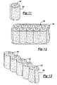
- FIG. 11 is a diagrammatic perspective view of a gel tube containing microphase change crystals for cooling of battery cells of a battery pack according to the principles of the present invention
- FIG. 12 is a diagrammatic perspective view of a gel blanket containing microphase change crystals for cooling cells of a battery pack according to the principles of the present invention
- FIG. 13 is a diagrammatic perspective view of a plastic carrier containing microphase change crystals for cooling a plurality of cells according to the principles of the present invention
- FIG. 14 is a schematic illustration of the method of forming the plastic carrier shown in FIG. 13 ;
- FIG. 15 is a diagrammatic perspective view of a heat sink made of conductive material including microphase change crystals for providing a heat sink for cells of a battery pack, according to the principles of the present invention
- FIG. 16 is a diagrammatic view of an exemplary battery pack including a plurality of cells surrounded by a suspension medium including microphase change crystals suspended in the suspension medium according to the principles of the present invention
- FIG. 17 is a perspective view of a heat sink having fins for cooling cells of a battery pack and including phase change material between the fins for enhancing the cooling properties of the heat sink according to the principles of the present invention
- FIG. 18 is a cross-sectional view of a power tool including a plastic housing including a motor within the housing and an integrally formed handle portion, with a battery pack having a metal housing for conducting heat away from the plurality of cells according to the principles of the present invention
- FIG. 19A is a side schematic diagram of a battery pack having a plurality of cells movable within the battery pack for moving the cells from a warm portion of the battery pack to a cooling portion of the battery pack according to the principles of the present invention
- FIG. 19B is a front schematic diagram of the battery pack shown in FIG. 19A ;
- FIG. 20 is a schematic diagram of a power tool including a fan provided in the battery pack for cooling a cell cluster within the battery pack and a separate fan for cooling the motor of the power tool;
- FIG. 21 is a schematic illustration of a standard battery pack and tool/charger system
- FIG. 22 is a schematic diagram of a tool and charger system in combination with a battery pack and employing a modular cooling system which is detachable to and from the tool/charger and/or battery pack for providing selective cooling to the battery pack when needed;
- FIG. 23 is a schematic diagram of a battery system including a plurality of cells disposed within a housing and including a rheological fluid within the housing for conducting heat away from the cell cluster;
- FIG. 24 is a schematic diagram of a circuit for disabling a battery pack when a temperature of the cells exceeds a predetermined level
- FIG. 25 is a diagram of a circuit for activating temperature gauges disposed on the battery pack for indicating to a user when the pack reaches a predetermined temperature
- FIG. 26 is a diagrammatic illustration of a battery pack for a power tool including a temperature gauge disposed on the exterior of the battery pack according to the principles of the present invention.
- a cordless device such as a power tool
- the cordless device 1 ordinarily includes a clam shell type housing 2 .
- the housing 2 includes a mechanism 3 to couple the housing 2 with a battery pack 4 .
- the cordless device 1 includes electrical elements 5 which couple with corresponding electrical elements 6 of the battery pack 8 .
- the device 1 includes a trigger 7 which is activated for energizing a motor 8 provided within the housing 2 , as is well known in the art.
- a plurality of battery cells 9 are disposed within the battery pack 4 .
- Battery pack 4 With reference to FIG. 1B , the functional control features of a battery pack 4 and battery charger 11 , according to the principles of the present invention, will be described.
- the power connections for charging and discharging the battery pack 4 are through terminals A and B.
- a pack ID (identification) component 12 which, when used with the charger 11 or tool 1 , can define the battery's chemistry, capacity, and/or other battery characteristics to either the charger's electronic control unit 13 or the tool electronic control unit 14 (see FIG. 1C ).
- Battery pack 4 also has one or more temperature sensor (such as a thermistor) 15 connected to both the charger unit 11 via connector 16 and the electronic control 17 inside the battery pack 4 .
- the electronic control 17 is responsible for the protection of the cells 9 for any condition exposed on the terminals A, B by the user (charger, tool, and/or user tampering).
- the discharge or charge current can be clamped or discontinued by the use of the semi-conductor devices Q 1 and Q 2 .
- the electronic circuit is powered by an internal power supply 18 as shown and the semi-conductor devices Q 1 , Q 2 are linked through a driver circuit 19 .
- the charger electronic control 13 When connected to a charger unit 11 , the charger electronic control 13 can be powered from the battery's power supply 18 through terminals A and C. This is only exemplary as other means for powering the charger electronic control 13 can be employed. Battery and charger information can be exchanged through serial data on terminal D and E. The charger electronic control 13 then will drive the power controller 20 to deliver the desired voltage and current to the battery pack 4 .
- the battery pack 4 is shown connected to a smart tool 1 .
- the tool 1 also has an electronic control 14 that can be powered from the battery power supply 18 through terminals A and C.
- the tool 1 contains a mechanical switch S 1 that pulls terminal B high when the semi-conductor Q 1 is off. If semi-conductor Q 1 is left off while the battery pack 4 is dormant, and suddenly the trigger 21 is pulled, terminal B could be used to wake the battery pack 4 from a dormant mode of operation.
- the tool electronic control 14 could be programmed to read the trigger 21 position and report that data back to the battery electronic control 14 through serial line D and E.
- the battery electronic control 14 will vary the PWM duty cycle through semi-conductor Q 1 to obtain a desired motor speed in the tool 1 . While semi-conductor Q 1 is off, the diode D 1 in the tool 1 will re-circulate any inductive motor current to prevent voltage spikes.
- An alternative tool not having a smart controller may just have the trigger switch 21 configured as a potentiometer and connected to terminals A, D or E, and C.
- the battery electronic control 17 would then command the semi-conductor Q 1 to switch at the desired duty cycle to create the intended motor speed.
- Even less intelligent tools could exist as on/off tools. These require only the connection to terminals A and B for operation.
- the present application is directed to several methods of managing the thermal environment around the battery cells of a battery pack as used in a power tool and during charging of the batteries when applied to a battery charger unit.
- a battery pack 30 is provided in connection with a charger unit 32 .
- the battery pack 30 includes a housing 34 having a plurality of battery cells 9 mounted therein.
- the battery cells 9 may be disposed between a pair of metal plates 38 which are sandwiched on opposite sides of the battery cells 9 .
- the plates 38 may be provided with liquid passages 40 , including an inlet passage 42 and an outlet passage 44 , which extend through the plates 38 .
- the passages 40 are either metal (such as copper, aluminum, etc.) tubing or heat pipes running through the plates 38 .
- the copper tubes or heat pipes 40 are used to carry the heat away from the plates so they never reach temperature equilibrium with the cells. Since they never reach equilibrium, they can continuously carry heat away.
- a fluid such as water is pumped from a reservoir 46 provided in the charger unit 32 by a pump 48 .
- the heat exchanger 50 may be provided for extracting heat from fluid returned to the storage vessel 46 .
- the heat exchanger 50 can include fins for increasing the heat transfer, or alternatively, an active cooling system such as a refrigeration system or fan can be utilized for withdrawing heat from the fluid in the storage vessel 46 .
- the inlet and outlet 42 , 44 of the fluid passages 40 in the battery pack 30 can be connected to corresponding tubing in the charger unit 32 in order to provide a fluid connection with the fluid passage 52 coming from pump 48 and the return passage 54 . If the system of FIG. 2 is utilized including heat pipes, the heat pipes would be terminated into a heat sink mounted within the charger unit or the battery pack. When the battery pack is placed in the charger, a fan would blow air through the heat sink to carry the heat generated in the pack into the air.
- heat transfer is dependent on the mass flow rate of the fluid.
- a higher volume of fluid increases the amount of heat that can be carried away.
- the flow rate can also be changed based on temperature inputs from the pack.
- Heat transfer is dependent on the working fluid.
- the working fluid could be selected so that it maximizes performance across all temperature ranges and environmental conditions while maintaining low cost and high reliability.
- the copper tube method could be reversed to heat the pack if the pack is below the minimum charging temperature. Because the movement and type of fluid can be completely controlled, this method has a greater capacity to remove heat than the heat pipe method. If the working fluid is cooled below ambient, for example, by using a refrigeration device, there is a greater capacity for removing heat from the pack.
- the heat pipe method also has numerous advantages.
- the heat pipe method is a completely enclosed system that does not require fluid to move across the pack/charger boundary. If multiple independent heat pipes are used in the system, the system would continue to work if the pack/cooling system was damaged.
- the heat pipe system is simpler in that heat pipes create fluid flow through a wicking method. This eliminates the need for pumps or methods to create fluid flow. Because air cooling from the charger is still required to cool the heat sink where the heat pipes terminate, it is possible to combine this system with a traditional fan cooled system to enhance pack cooling further.
- a battery pack 60 is provided along with a refrigeration system for cooling the battery cells within the pack 60 .
- the refrigeration system may be provided within a charger unit for cooling the pack during recharge of the battery pack.
- the battery pack 60 acts as the evaporator in a standard refrigeration cycle.
- the refrigerant is compressed by a compressor 62 . It is then passed to a condenser 64 where excess heat is removed and the coolant is liquefied. From the condenser 64 , the liquid coolant is passed to an expansion valve 66 where it is throttled to a sub-cooled liquid.
- the liquid then passes into interior passages in the battery pack 60 where it is evaporated to a gas by absorbing heat from the pack 60 .
- the vapor then passes back to the compressor 62 to repeat the cycle.
- the refrigeration system as illustrated in FIG. 3 , can be employed in the charger unit 32 , as illustrated in FIG. 2 , wherein the compressor, condenser, and evaporator 66 are each disposed within the battery charger unit.
- the connection with the battery pack can be obtained in the same manner as illustrated and described with reference to FIG. 2 .
- a battery pack 70 including a plurality of battery cells 72 disposed within a housing 74 .
- the housing 74 is filled with a fluid which surrounds the battery cells 72 .
- the housing 74 is provided with a water-tight seal and includes electrical contacts 78 that are insert molded into the plastic enclosure 74 .
- At least one heat conducting plate 80 such as an aluminum plate, may be insert molded into a sidewall of the housing 74 in contact with the fluid 76 for conducting heat from the fluid 76 to the exterior of the housing 74 .
- a heat sink 82 may be provided in contact with the heat conducting plate 80 when the battery pack 70 is inserted into the power tool or received in a battery charger.
- the heat sink 82 helps to conduct heat away from the heat conducting plate 80 and is provided with fins, or is otherwise passively or actively cooled to provide additional cooling to the heat conducting plate 80 .
- the fluid 76 within the housing 74 is optionally stirred by an ultrasonic device 84 or other device which is turned on by a pack controller 414 to stir the fluid in the enclosure.
- the stirring of the fluid increases heat transfer form the cells 72 to the fluid 76 and from the fluid 76 to the heat conducting plate 80 .
- the additional mass in the system due to the fluid gives a larger thermal mass that also improves the transient performance of the pack 70 .
- hot spots in the pack 70 are reduced or eliminated due to the improved heat transfer within the system that is being stirred.
- the cooling system requires little to no energy for the pack 70 to operate.
- the stirring device 84 If the stirring device 84 is turned on, its current draw would be low enough so as not to have a significant impact on the run time of the pack 70 .
- the system has the potential to absorb/dissipate a tremendous amount of heat, thereby allowing for high charge and discharge rates.
- the cooling method includes no moving parts and is, therefore, durable and reliable.
- a battery pack 90 is shown inserted in a battery charger 92 .
- a compressor 94 is provided in connection with the charger unit 92 to provide compressed air through a high pressure air line 96 that introduces high pressure air through a vent passage 98 in the housing 100 of the battery pack 90 .
- the housing 100 may be provided with additional vent passages 102 which allow air to escape from within the battery pack 90 and, therefore, carry away heat from the battery cells 104 .
- the compressor 94 may be provided within the charger or as a separate unit connected to the charger unit 92 .
- a valve 106 can be provided within the charger unit 92 in the high pressure air line for controlling the flow of high pressure air for cooling the pack 90 .
- the charger controller 13 may be used to open and close the valve 106 in response to a detected high temperature. As air passes through the nozzle and expands back to ambient pressure, its temperature will drop. By designing the system such that the temperature can drop below the ambient, the air's ability to carry away heat from the pack is improved.
- Another advantage to this method is that as the air passes through the nozzle, its velocity will increase. This, in turn, means that air moving through the pack is moving at higher speed than what would be possible with a fan. By raising the air velocity, the heat transfer coefficient improves allowing for better heat transfer from the pack to the air. Secondly, increasing the air velocity increases the likelihood of turbulence which further improves the air's ability to remove heat.
- the compressor 94 which may preferably be of a mini-compressor type could be cycled on and off as necessary to supply air through the pack any time during the charging cycle.
- This method of cooling may also be provided by providing a nipple on the back of the charger 92 or battery pack 90 that would plug into a portable compressor or shop air system 94 .
- the compressed air cooling system of the present invention improves cooling by using air that has a temperature lower than ambient and utilizes a high velocity air flow.
- the system is more robust than a standard air cool system that utilizes a fan, and the system can be used to provide cooling at any time during the charge cycle.
- This compressed air system may be combined with a Hirsch Vortex device to further enhance the cooling by further reducing the air temperature as it passes into the battery pack 90 .
- a battery pack 110 is provided in connection with a battery charger unit 112 .
- the battery pack 110 includes a cell cluster 114 and a thermistor 15 which senses the temperature of the cell cluster 114 .
- the thermistor 15 is electrically connected to a control unit 13 provided within a charger unit 112 .
- the charger control unit 13 controls discharge of CO 2 from a CO 2 cartridge 120 by opening and closing pressure relief valve 122 .
- the pressure relief valve 122 is in communication with a passage 124 which communicates with a passage 126 provided within the housing 130 of the battery pack 110 .
- the control unit 13 When the control unit 13 detects the temperature of the battery pack exceeding a predetermined level (via the signal from thermistor 15 ), the control unit 13 opens valve 122 to release CO 2 into the battery pack 110 for cooling the battery cell cluster 114 .
- the battery pack 110 may include vent passages 128 provided in the housing 130 for allowing escape of the air and CO 2 within the battery pack 110 . If the pressure is released from the CO 2 cartridge 120 , the temperature of the gas coming from the cartridge is often less than 0 degrees Celsius. This greatly reduces the ambient temperature in the pack thereby improving the heat transfer from the cells to the ambient. This method of cooling can be controlled by pulsing the pressure release valve 122 on an as-needed basis to maintain the pack in the operating temperature range.
- a pressure sensor 132 can be employed with the pressure relief valve 122 for providing pressure signals to the controller 13 .
- the control unit 13 can provide a signal to an audible or visual signal device 133 to indicate to a user that the CO 2 cartridge needs to be replaced.
- the control unit 13 can also deactivate the charger unit so that the charger unit is not utilized until the CO 2 cartridge is replaced and the pressure sensed by pressure sensor 132 achieves a predetermined level.
- the use of a CO 2 cooling system provides active cooling for a low cost with few moving parts. Due to the low number of moving parts, the system is highly reliable. The system is user serviceable to minimize down time, and can be constructed using readily available parts and takes up relatively little space.
- a similar system is implemented by providing a CO 2 cartridge 134 within the battery pack 140 between the cells 136 .
- a controller unit 17 is employed within the pack 140 along with a thermistor 15 for detecting a temperature within the battery pack 140 .
- the control unit 17 controls discharge of CO 2 from the CO 2 cartridge in the same manner as controller 13 , as discussed above.
- the system of FIG. 7 has two advantages over utilizing the CO 2 cartridge in the charger unit. First, the surface at the CO 2 cartridge will cool as gas is released, and it can then absorb some of the heat from the battery cells. Second, the system can be activated during discharge as well as during charging of the battery pack 140 .
- the high pressure CO 2 cartridge can be fully discharged to rapidly cool the cells.
- the CO 2 cartridge 150 is provided in a charger unit 152 and has a nozzle portion 154 which discharges directly through a passage 156 provided in the housing 158 of a battery pack 160 . Vent holes 162 are provided in the sides of the pack housing 158 allowing CO 2 to escape from the pack 160 while more CO 2 is introduced.
- the use of CO 2 cartridges provides a low cost temperature control device. The CO 2 cartridges can be easily replaced by a user.
- the pack input/output can be shut off by the controller until the cartridge is replaced by the user.
- the use of a CO 2 cartridge for discharge during a runaway situation prevents a hazardous situation from occurring.
- the CO 2 cartridge can be placed in the battery pack itself, as illustrated in FIG. 7 , or within the charger unit, as illustrated in FIGS. 6 and 8 . When the CO 2 cartridge is placed within the pack, the CO 2 cartridge does not consume much more space than one additional cell.
- a circuit diagram is provided in which the battery cells 164 provided in the battery pack 160 are connected to a charger unit 152 .
- a thermistor 15 is provided for sensing a temperature of the cells 164 and providing a signal to a charger controller 13 provided within a charger unit 152 .
- the charger controller 13 Upon detection of the battery temperature exceeding a predetermined level, the charger controller 13 sends a signal to activate a solenoid actuation device 170 for discharging CO 2 from the CO 2 cartridge 150 .
- the CO 2 cartridge has a nozzle communicating with a passage in the battery pack 160 so that the discharged CO 2 engulfs the battery cells 164 within the pack 160 for rapid cooling thereof.
- FIG. 10 an alternative embodiment of the control circuit is illustrated in which the CO 2 cartridge 134 is disposed within the battery pack 140 and a battery controller 17 receives a signal from a thermistor 15 which detects a temperature of the battery cells 136 . Upon detection of a temperature of the battery cells exceeding a predetermined level, the battery controller 17 provides a signal to a solenoid device 176 for actuating the CO 2 cartridge 134 to discharge within the battery pack 140 for cooling the battery cells 136 . With the setup illustrated in FIG. 10 , the CO 2 cartridge and controller are fully contained within the battery pack.
- the temperature is monitored by the controller 17 and if an over-temperature condition is detected, the battery controller 17 activates the solenoid 176 to open the CO 2 cartridge 134 .
- the CO 2 could be released during discharge, for example, to prevent thermal runaway if the pack was shorted.
- the CO 2 cartridge container itself rapidly cools during discharge, it acts like a heat sink in the pack to draw heat away from the battery cells 136 .
- a cooling method which utilizes the latent heat of fusion of a phase-change material to maintain the battery pack at the melting temperature of the phase-change material. As the material changes phase (in this case from a solid to a liquid), the temperature remains constant until the phase change has completely occurred.
- a battery cell 180 is provided with a gel tube 182 wrapped around the cell 180 .
- the gel tube 182 is a thin plastic sheet having inner and outer layers that contain a gel solution.
- the gel is comprised of a fluid medium such as water or other fluids with micro phase-change crystals suspended in the solution.
- micro phase-change crystals are 25-50 microns in size and consist of a wax-type material (i.e., paraffin) that is encapsulated in a thermoplastic.
- a wax-type material i.e., paraffin
- the heat is transferred to the gel tube 182 .
- the melt temperature of the wax i.e., 50 degrees Celsius
- the phase-change begins.
- the wax melts internal to the thermoplastic shells, it will absorb the heat given off by the cell. Since the gel is able to absorb the heat at the same rate the cell is dissipating the heat, the system will remain at a constant temperature. As long as the amount of micro-phase change crystals used is enough to ensure that the phase change takes longer than the charge or discharge of the battery pack, the system remains below the specified temperature.
- the same affect can be accomplished by wrapping a cell cluster 184 in a gel blanket 186 .
- the blanket 186 contains micro-phase change crystals suspended in a fluid solution for absorbing heat from the entire pack as it heats up.
- the gel tube or gel blanket cooling system is a passive method of cooling with no moving parts and nothing to wear out.
- the system is fully contained within the battery pack and does not require any air flow through the pack or heat sinking to the outside of the pack, although heat sinking and air flow can also be utilized in combination with the gel tube or blanket.
- This system is limited by time by delaying the temperature rise, and is not limited by the amount of heat that can be absorbed.
- the system can be cycled thousands of times.
- the wax re-solidifies allowing the process to repeat. Since the wax is encapsulated within its own shell, there is no expansion of the material as it melts. Since the crystals are suspended in a fluid solution, there is an added benefit in that the thermal run time is extended by having to heat the mass of the fluid solution to the phase transition temperature before beginning the phase transition process.
- some battery packs include paper or plastic insulating tubes around the cell.
- the gel tube or gel blanket replaces the paper tube and, therefore, does not take up a significant amount of additional space.
- the cell carrier 190 is formed from a thermoplastic material that includes micro-phase change crystals which are suspended in the plastic of the carrier 190 .
- the thermoplastic material used for making the plastic carrier and battery housing is injected through a conventional screw-type plastic injection molding device 194 into which micro-phase change crystals 196 are introduced near the outlet end of the screw 194 .
- the thermoplastic material 192 mixed with micro-phase change crystals 196 is introduced into a mold cavity 198 of a mold 200 for forming the plastic carrier and/or housing of the battery pack.
- the battery cells 202 generate heat during charge or discharge, the heat is transferred to the carrier 190 and housing where it is absorbed by the wax in the crystals changing state. Since the crystals have a high latent heat capacity, the system is able to absorb the heat at the same rate the cell is dissipating the heat, maintaining the system at a constant temperature. As long as the amount of micro-phase change crystals used is enough to ensure the phase change takes longer than the charge or discharge of the battery pack, the system remains below the specified operating temperature maximum.
- the system of FIG. 13 provides a passive method of cooling with no moving parts and nothing to wear out.
- the cooling system is integrated into the plastic housing eliminating the need to provide additional manufacturing processes to add gel or crystals to the pack.
- the system is limited by the time required for the phase change crystals to change phase and not by the amount of heat that can be absorbed.
- the system can be cycled thousands of times. Once a temperature drops below the melt temperature, the wax re-solidifies allowing the process to be repeated.
- the system could be further enhanced by using thermally conductive plastic to transfer some of the heat to the ambient. The system would work even if the crystals were damaged by the injection molding process or due to pack damage, etc. since the wax is an integrated part of the pack housing.
- micro phase-change crystals are used to form a highly efficient heat sink 210 .
- the heat sink 210 is formed from a heat conductive material such as aluminum, copper, or carbon fiber with micro phase-change crystals dispersed throughout the matrix.
- the heat sink 210 provides the benefits of both the micro phase-change crystals and the high conductivity metal.
- the micro phase-change crystals 212 can be inserted between the fins 214 of an aluminum, copper, or other heat conductive material heat sink 216 which is disposed adjacent to battery cells 202 .
- the cooling systems disclosed in FIGS. 15 and 17 provide a passive method of cooling with no moving parts and nothing to wear out.
- the system is contained within a battery pack, and does not require any air flow through the pack. This system can be cycled thousands of times. Once the temperature drops below the melt temperature, the phase-change crystals re-solidify, allowing the process to repeat.
- a battery pack 220 is provided with a plurality of cells 222 disposed within a housing 224 .
- the housing 224 is filled with a wax, powder, or other solution 226 which includes micro-encapsulated phase-change material.
- the micro-encapsulating phase-change material begins to change phase. This phase change occurs at a relatively constant temperature, maintaining the temperature of the cells below their specified operating temperature.
- the battery housing can be constructed of a metal material, such as aluminum, which would act as a large heat sink for the heat generated in the cells. The heat is conducted through the wax, powder, or solution to the metal housing and is conducted to the ambient.
- phase-change material 16 provides a passive method of cooling with no moving parts and nothing to wear out.
- the system is fully contained within the battery pack, and does not require any air flow through the pack. This system is limited by time, not by the amount of heat that can be absorbed.
- the system can be cycled thousands of times and once the temperature drops below the melt temperature, the phase-change material re-solidifies, allowing the process to repeat.
- the phase-change material is provided in a slurry solution, the crystals are suspended in a fluid solution, so there is an added benefit in that the thermal run time is extended by having to heat the mass of the fluid solution to the transition temperature before beginning the transition process of the phase change.
- a power tool 230 is provided with a plastic tool housing 232 including a handle portion 234 .
- a motor 236 and drive mechanism 238 are disposed in the tool housing 232 .
- the drive mechanism 238 can include gear reduction mechanisms, drive shafts, reciprocation devices, etc., as are well known in the power tool art.
- a battery pack 240 is mounted to the tool housing and includes a metal battery housing 242 .
- the housing 242 includes a plurality of cells 244 disposed therein.
- the use of a plastic tool housing provides all the benefits of the use of plastics for assembling the tool and molding the housing.
- the use of a metal battery housing adds the additional heat conducting characteristics of the battery housing to help in removing heat from the battery cells 244 .
- a battery pack 250 is provided with a plurality of cells 252 .
- the cells 252 are disposed on a rotary wheel mechanism 254 which allows the battery cells to be moved from hot portions of the battery pack to cooler portions of the battery pack 250 .
- a cold source 256 such as a heat sink, fan, Peltier device, or liquid cooling system can be employed in one portion of the battery pack 250 so that the cooling feature 256 provides adequate cooling of the cells disposed in the vicinity of the cooling feature.
- additional cells which are not disposed in proximity to the cooling feature may not be properly cooled.
- the rotary wheel 254 can be rotated to move hot cells from the hot area within the battery pack to a cooler portion of the battery pack in order to remove heat from the cells.
- the cooling position can include a heat sink or other actively cooled area within the pack 250 where the heat from the hot cells can be extracted and expelled, and the cells within the battery pack can be continually moved or rotated or swapped so that the battery cells are maintained within a predetermined temperature range.
- the swapping or movement of the cells 252 can be performed manually by rotation of a knob 258 mounted to the rotary wheel 254 upon indication to a user that certain cells have achieved an undesirable temperature, or can be performed automatically by a control system and drive mechanism for driving the rotary wheel 254 .
- Terminal brushes 259 a , 259 b provide an electrical contact between the rotary wheels 254 a , 254 b and terminals 257 to allow the rotary wheel 254 to be rotated.
- a power tool 260 including a tool housing 262 including a handle portion 264 .
- a motor 266 and drive mechanism (not illustrated) are disposed in the tool housing 262 , as is known in the art.
- a battery pack 270 including a battery housing 272 is releasably connected to the tool housing 262 .
- the battery pack 270 includes a cell cluster 274 disposed within the housing 272 as well as a fan 276 .
- the fan 276 is a DC motor fan that is controlled by a controller provided within the battery pack which senses a temperature of the cell cluster 274 and activates the fan 276 for cooling the cell cluster once the cell cluster reaches a predetermined temperature.
- the fan 276 draws air into the housing 272 of the battery pack 270 .
- the housing 272 can be configured with vents in order to control the air flow through the battery pack 270 such that air can be expelled into the tool housing 262 to be utilized for additional cooling of the motor 266 , or can alternatively be designed to expel the air into the ambient directly from the battery pack housing 272 .
- An additional DC motor driven fan 280 or a fan coupled to the tool drive motor can optionally be provided within the tool housing 262 for providing direct cooling for the motor 266 .
- FIG. 21 a schematic illustration of a battery pack 290 attached to either a tool or a battery charger 292 is shown. During this normal setup, the battery pack is directly connected to the tool/charger.
- a modular cooling system including an optional cooling system 294 that can be mounted to the tool/charger 292 or to the pack 290 , or both.
- the cooling system 294 includes a fan unit disposed within the cooling system pack for blowing air through the battery pack 290 for cooling cells therein.
- the cooling system 294 is removable from the battery pack 290 so that in lighter duty applications, the tool 292 and battery pack 290 can be utilized without the cooling system 294 .
- the cooling system 294 can be snapped onto the tool 292 or pack 290 for providing desired cooling of the cells within the battery pack 290 .
- the battery pack 290 is placed on a charger 292 (in FIG.
- the cooling system 294 can be employed for blowing air through the pack in order to cool the cells within the pack 290 .
- the modular arrangement of the cooling system 294 allows the cooling system 294 to be sold as a separate item or as a kit with a tool, charger, and pack system.
- the modular cooling system 294 can also take the form of a heat sink or other active cooling systems, such as a fluid cooling system as disclosed above, which can be removably mounted to the pack 290 or tool/charger 292 .
- a battery pack 300 including a housing 302 in which a cell cluster 304 is disposed.
- a rheological fluid 306 is provided in the housing 302 and surrounds the cell cluster 304 .
- Theological fluid has good heat conducting characteristics and, as is known in the art, when a magnetic field is applied to the rheological fluid, the rheological fluid changes from a generally liquid state to a solid state.
- a conductor coil 308 is provided within the housing 302 to generate a pulsing magnetic field to cause the rheological fluid 306 to alternate solid and liquid states that causes it to circulate around the cell cluster 304 .
- the circulating rheological fluid 306 withdraws heat from the cell cluster and provides cooling thereof.
- a battery pack control circuit is provided within the battery pack 310 which includes a plurality of cells 312 .
- the circuit includes a thermistor 314 which detects the temperature of the cells 312 and opens a switch, breaker, or MOSFET, etc. 316 , in order to disable the electrical connection with the cells 312 in order to disable the battery pack 310 from discharging or charging the cells.
- the control circuit ensures that the batteries 312 cannot continue to be charged or discharged when a temperature of the battery cells exceed a predetermined temperature.
- a battery pack 320 is schematically shown including a plurality of cells 322 employing a circuit, including a thermistor 324 which senses a temperature of the cells 322 and provides an appropriate signal to a temperature gauge 326 which is mounted on the exterior surface of the housing 328 of the battery pack 320 .
- the temperature gauge 326 (shown in FIG. 26 ) shows the user when the pack is getting too hot for continued use.
- the temperature gauge 326 provided on the battery pack 320 can be used in combination with other cooling techniques provided in the present disclosure for indicating to a user that the cooling technique needs to employed. In particular, the technique illustrated in FIG.
- fluid cooling is provided to the battery pack via a stored fluid chamber and pump system that swaps the warm fluid within the pack with a cooler fluid can be utilized.
- the gauge can also be utilized in combination with the system disclosed in FIG. 19 as an indicator to the user that the batteries need to be manually moved or swapped to a cooler position within the battery pack.
- This system can also be utilized with the system disclosed in FIGS. 22A and 22B to indicate to a user that a modular cooling system needs to be added to the battery pack in order to actively cool the cells within the pack.
Abstract
Description
Claims (26)
Priority Applications (4)
| Application Number | Priority Date | Filing Date | Title |
|---|---|---|---|
| US11/075,179 US7270910B2 (en) | 2003-10-03 | 2005-03-08 | Thermal management systems for battery packs |
| PCT/US2005/007721 WO2005086851A2 (en) | 2004-03-10 | 2005-03-09 | Thermal management systems for battery packs |
| EP05725082.1A EP1723686B1 (en) | 2004-03-10 | 2005-03-09 | Thermal management systems for battery packs |
| US11/851,620 US20080003491A1 (en) | 2003-10-03 | 2007-09-07 | Thermal management systems for battery packs |
Applications Claiming Priority (9)
| Application Number | Priority Date | Filing Date | Title |
|---|---|---|---|
| US50795503P | 2003-10-03 | 2003-10-03 | |
| US51012503P | 2003-10-14 | 2003-10-14 | |
| US51012803P | 2003-10-14 | 2003-10-14 | |
| US54032304P | 2004-02-02 | 2004-02-02 | |
| US55189104P | 2004-03-10 | 2004-03-10 | |
| US55180304P | 2004-03-11 | 2004-03-11 | |
| US10/954,222 US20050073282A1 (en) | 2003-10-03 | 2004-10-01 | Methods of discharge control for a battery pack of a cordless power tool system, a cordless power tool system and battery pack adapted to provide over-discharge protection and discharge control |
| US10/959,193 US7508171B2 (en) | 2003-10-14 | 2004-10-07 | Protection methods, protection circuits and protective devices for secondary batteries, a power tool, charger and battery pack adapted to provide protection against fault conditions in the battery pack |
| US11/075,179 US7270910B2 (en) | 2003-10-03 | 2005-03-08 | Thermal management systems for battery packs |
Related Parent Applications (2)
| Application Number | Title | Priority Date | Filing Date |
|---|---|---|---|
| US10/954,222 Continuation-In-Part US20050073282A1 (en) | 2003-10-03 | 2004-10-01 | Methods of discharge control for a battery pack of a cordless power tool system, a cordless power tool system and battery pack adapted to provide over-discharge protection and discharge control |
| US10/959,193 Continuation-In-Part US7508171B2 (en) | 2003-10-03 | 2004-10-07 | Protection methods, protection circuits and protective devices for secondary batteries, a power tool, charger and battery pack adapted to provide protection against fault conditions in the battery pack |
Related Child Applications (1)
| Application Number | Title | Priority Date | Filing Date |
|---|---|---|---|
| US11/851,620 Division US20080003491A1 (en) | 2003-10-03 | 2007-09-07 | Thermal management systems for battery packs |
Publications (3)
| Publication Number | Publication Date |
|---|---|
| US20050202310A1 US20050202310A1 (en) | 2005-09-15 |
| US20070128505A9 US20070128505A9 (en) | 2007-06-07 |
| US7270910B2 true US7270910B2 (en) | 2007-09-18 |
Family
ID=34922235
Family Applications (2)
| Application Number | Title | Priority Date | Filing Date |
|---|---|---|---|
| US11/075,179 Active US7270910B2 (en) | 2003-10-03 | 2005-03-08 | Thermal management systems for battery packs |
| US11/851,620 Abandoned US20080003491A1 (en) | 2003-10-03 | 2007-09-07 | Thermal management systems for battery packs |
Family Applications After (1)
| Application Number | Title | Priority Date | Filing Date |
|---|---|---|---|
| US11/851,620 Abandoned US20080003491A1 (en) | 2003-10-03 | 2007-09-07 | Thermal management systems for battery packs |
Country Status (3)
| Country | Link |
|---|---|
| US (2) | US7270910B2 (en) |
| EP (1) | EP1723686B1 (en) |
| WO (1) | WO2005086851A2 (en) |
Cited By (75)
| Publication number | Priority date | Publication date | Assignee | Title |
|---|---|---|---|---|
| US20080150375A1 (en) * | 2005-07-26 | 2008-06-26 | Jefcom Co., Ltd. | Electric power tool |
| US20080259569A1 (en) * | 2007-04-20 | 2008-10-23 | Ama Precision Inc. | Thermally enhanced battery module |
| US20080290745A1 (en) * | 2007-05-24 | 2008-11-27 | Hilti Aktiengesellschaft | Electrical hand-held power tool with cooling of electronics |
| US20090314382A1 (en) * | 2005-11-04 | 2009-12-24 | Peter David Capizzo | System for replenishing energy sources onboard different types of automatic vehicles |
| US20100028758A1 (en) * | 2008-08-04 | 2010-02-04 | Eaves Stephen S | Suppression of battery thermal runaway |
| US20100063647A1 (en) * | 2008-09-11 | 2010-03-11 | Joseph Yeh | Outdoor enclosure cooling system operating at off-peak hours |
| US20100141186A1 (en) * | 2007-04-24 | 2010-06-10 | Steffen Katzenberger | Electric tool and device switch for an electric tool |
| US20100269355A1 (en) * | 2009-04-28 | 2010-10-28 | Dezhong Yang | Control method for motor-driven shears |
| US20100291427A1 (en) * | 2009-05-15 | 2010-11-18 | Sinoelectric Powertrain Corporation | Modular powertrain, systems, and methods |
| US20100291419A1 (en) * | 2009-05-15 | 2010-11-18 | Sinoelectric Powertrain Corporation | Battery pack heat exchanger, systems, and methods |
| US20100291426A1 (en) * | 2009-05-15 | 2010-11-18 | Sinoelectric Powertrain Corporation | Flexible fusible link, systems, and methods |
| US20100291418A1 (en) * | 2009-05-15 | 2010-11-18 | Sinoelectric Powertrain Corporation | Battery packs, systems, and methods |
| DE102009029093A1 (en) | 2009-09-02 | 2011-03-03 | Robert Bosch Gmbh | Method for heating a rechargeable battery, charger and additional element |
| US20110064490A1 (en) * | 2009-09-14 | 2011-03-17 | Ricoh Company, Ltd. | Fixing device and image forming apparatus incorporating the fixing device |
| US20110197389A1 (en) * | 2010-02-12 | 2011-08-18 | Makita Corporation | Electric tool powered by a plurality of battery packs and adapter therefor |
| US20120148881A1 (en) * | 2001-11-27 | 2012-06-14 | Tony Quisenberry | Method and system for automotive battery cooling |
| US20130015789A1 (en) * | 2010-03-26 | 2013-01-17 | Panasonic Corporation | Electric tool |
| US8486283B2 (en) | 2010-11-02 | 2013-07-16 | Sinoelectric Powertrain Corporation | Method of making fusible links |
| US20130330577A1 (en) * | 2012-06-11 | 2013-12-12 | Nucleus Scientific, Inc. | Dynamic pressure control in a battery assembly |
| US8641273B2 (en) | 2010-11-02 | 2014-02-04 | Sinoelectric Powertrain Corporation | Thermal interlock for battery pack, device, system and method |
| US8659261B2 (en) | 2010-07-14 | 2014-02-25 | Sinoelectric Powertrain Corporation | Battery pack enumeration method |
| US8722222B2 (en) | 2011-07-11 | 2014-05-13 | Gentherm Incorporated | Thermoelectric-based thermal management of electrical devices |
| US20140148799A1 (en) * | 2012-11-27 | 2014-05-29 | Covidien Lp | Surgical instruments |
| US20140158340A1 (en) * | 2012-12-11 | 2014-06-12 | Caterpillar Inc. | Active and passive cooling for an energy storage module |
| US8779728B2 (en) | 2010-04-08 | 2014-07-15 | Sinoelectric Powertrain Corporation | Apparatus for preheating a battery pack before charging |
| US8786233B2 (en) | 2011-04-27 | 2014-07-22 | Medtronic Xomed, Inc. | Electric ratchet for a powered screwdriver |
| US20140215839A1 (en) * | 2013-02-01 | 2014-08-07 | Makita Corporation | Power tool, such as a portable circular saw, having improved braking and cooling |
| US8813866B2 (en) | 2010-02-12 | 2014-08-26 | Makita Corporation | Electric tool powered by a plurality of battery packs and adapter therefor |
| US8821220B2 (en) | 2008-08-20 | 2014-09-02 | Black & Decker Inc. | Power tool with interchangeable tool head |
| US20140246214A1 (en) * | 2011-10-06 | 2014-09-04 | Husqvarna Ab | Battery operated handheld power tool |
| US20140327396A1 (en) * | 2011-11-22 | 2014-11-06 | Marcin Rejman | System having a hand tool case and a hand tool battery |
| US8915091B2 (en) | 2005-04-08 | 2014-12-23 | Gentherm Incorporated | Thermoelectric-based thermal management system |
| US20150022125A1 (en) * | 2012-03-14 | 2015-01-22 | Hitachi Koki Co., Ltd. | Electric tool |
| US8974942B2 (en) | 2009-05-18 | 2015-03-10 | Gentherm Incorporated | Battery thermal management system including thermoelectric assemblies in thermal communication with a battery |
| US9071069B2 (en) * | 2010-04-07 | 2015-06-30 | Black & Decker Inc. | Controlled power fade for battery powered devices |
| US9103573B2 (en) | 2006-08-02 | 2015-08-11 | Gentherm Incorporated | HVAC system for a vehicle |
| US9172120B2 (en) | 2010-07-14 | 2015-10-27 | Sinoelectric Powertrain Corporation | Battery pack fault communication and handling |
| US9421682B2 (en) | 2011-07-18 | 2016-08-23 | Black & Decker Inc. | Multi-head power tool with reverse lock-out capability |
| US20160254577A1 (en) * | 2015-02-26 | 2016-09-01 | MAGNETI MARELLI S.p.A. | Cooling circuit with cooling fluid for lithium batteries, and a vehicle comprising said cooling circuit |
| US9455582B2 (en) | 2014-03-07 | 2016-09-27 | Apple Inc. | Electronic device and charging device for electronic device |
| US9479007B1 (en) | 2014-02-21 | 2016-10-25 | Apple Inc. | Induction charging system |
| US9520619B2 (en) | 2013-11-27 | 2016-12-13 | The Boeing Company | Methods of inerting lithium-containing batteries and associated containers |
| US9590282B2 (en) | 2013-10-29 | 2017-03-07 | Gentherm Incorporated | Battery thermal management systems including heat spreaders with thermoelectric devices |
| US9593969B2 (en) | 2013-12-27 | 2017-03-14 | Apple Inc. | Concealed electrical connectors |
| US20170093325A1 (en) * | 2015-09-25 | 2017-03-30 | Renesas Electronics Corporation | Semiconductor power module and drive system for electric motor |
| US20170120435A1 (en) * | 2015-10-30 | 2017-05-04 | Black & Decker Inc. | Control and power module for driving a brushless motor in a power tool |
| US9742047B2 (en) | 2014-08-11 | 2017-08-22 | Milwaukee Electric Tool Corporation | Battery pack with phase change material |
| US20170288436A1 (en) * | 2015-09-02 | 2017-10-05 | Ac (Macao Commercial Offshore) Limited | Power tool, battery pack, and combination, and method of controlling the same |
| US9812680B2 (en) | 2012-08-30 | 2017-11-07 | Apple Inc. | Low Z-fold battery seal |
| US9917335B2 (en) | 2014-08-28 | 2018-03-13 | Apple Inc. | Methods for determining and controlling battery expansion |
| US9956677B2 (en) | 2013-05-08 | 2018-05-01 | Black & Decker Inc. | Power tool with interchangeable power heads |
| US20180117728A1 (en) * | 2016-11-02 | 2018-05-03 | Makita Corporation | Power tool |
| US9966642B2 (en) | 2011-03-30 | 2018-05-08 | Covidien Lp | Insulation of rechargeable battery pack |
| US10003053B2 (en) | 2015-02-04 | 2018-06-19 | Global Web Horizons, Llc | Systems, structures and materials for electrochemical device thermal management |
| US10170811B2 (en) | 2013-01-14 | 2019-01-01 | Gentherm Incorporated | Thermoelectric-based thermal management of electrical devices |
| US10270141B2 (en) | 2013-01-30 | 2019-04-23 | Gentherm Incorporated | Thermoelectric-based thermal management system |
| USD853216S1 (en) | 2017-01-17 | 2019-07-09 | Tti (Macao Commercial Offshore) Limited | Power tool |
| USD853813S1 (en) | 2017-01-17 | 2019-07-16 | Tti (Macao Commercial Offshore) Limited | Power tool |
| USD858432S1 (en) | 2016-03-17 | 2019-09-03 | Tti (Macao Commercial Offshore) Limited | Battery pack |
| US10424821B2 (en) | 2017-04-03 | 2019-09-24 | Yotta Solar, Inc. | Thermally regulated modular energy storage device and methods |
| US10431858B2 (en) | 2015-02-04 | 2019-10-01 | Global Web Horizons, Llc | Systems, structures and materials for electrochemical device thermal management |
| USD862382S1 (en) | 2016-03-17 | 2019-10-08 | Tti (Macao Commercial Offshore) Limited | Battery pack |
| USD867279S1 (en) | 2016-03-17 | 2019-11-19 | Tti (Macao Commercial Offshore) Limited | Battery pack |
| US20190356029A1 (en) * | 2018-05-18 | 2019-11-21 | Lee Fei Chen | Charging device having thermoelectric module |
| US10629886B2 (en) | 2014-03-06 | 2020-04-21 | Apple Inc. | Battery pack system |
| US10637017B2 (en) | 2016-09-23 | 2020-04-28 | Apple Inc. | Flexible battery structure |
| US10700393B2 (en) | 2014-09-12 | 2020-06-30 | Gentherm Incorporated | Graphite thermoelectric and/or resistive thermal management systems and methods |
| US10827655B2 (en) | 2017-06-26 | 2020-11-03 | Milwaukee Electric Tool Corporation | Battery charger |
| USD911265S1 (en) | 2017-01-17 | 2021-02-23 | Tti (Macao Commercial Offshore) Limited | Battery pack |
| USD911961S1 (en) | 2017-04-03 | 2021-03-02 | Latent Heat Solutions, Llc | Battery container |
| USD926674S1 (en) | 2017-01-17 | 2021-08-03 | Tti (Macao Commercial Offshore) Limited | Battery pack with communication terminal |
| US11152557B2 (en) | 2019-02-20 | 2021-10-19 | Gentherm Incorporated | Thermoelectric module with integrated printed circuit board |
| US11309597B2 (en) | 2018-01-11 | 2022-04-19 | Carrier Corporation | Battery temperature control |
| US20230144937A1 (en) * | 2019-07-19 | 2023-05-11 | Milwaukee Electric Tool Corporation | Resettable electronic fuse for high-power devices |
| US11670808B2 (en) | 2019-12-03 | 2023-06-06 | Milwaukee Electric Tool Corporation | Charger and charger system |
Families Citing this family (193)
| Publication number | Priority date | Publication date | Assignee | Title |
|---|---|---|---|---|
| EP1475784B1 (en) * | 2002-02-13 | 2014-12-24 | Mitsubishi Kagaku Media Co., Ltd. | Optical recording method for rewritable optical recording medium |
| JP4694278B2 (en) * | 2005-04-28 | 2011-06-08 | 本田技研工業株式会社 | Battery unit structure |
| US20070027580A1 (en) * | 2005-07-14 | 2007-02-01 | Ligtenberg Chris A | Thermal control of an electronic device for adapting to ambient conditions |
| CA2628870C (en) * | 2005-11-08 | 2011-02-22 | Byd Company Limited | A heat dissipating device for a battery pack, and a battery pack using the same |
| US20080233470A1 (en) * | 2005-11-08 | 2008-09-25 | Byd Company Limited | Heat Dissipating Device for a Battery Pack, and Battery Pack Using the Same |
| KR100905392B1 (en) * | 2006-04-03 | 2009-06-30 | 주식회사 엘지화학 | Battery Pack Comprising Combined Temperature-controlling System |
| US20070259258A1 (en) * | 2006-05-04 | 2007-11-08 | Derrick Scott Buck | Battery assembly with temperature control device |
| JP4636030B2 (en) * | 2007-02-01 | 2011-02-23 | トヨタ自動車株式会社 | Power supply |
| JP4636031B2 (en) | 2007-02-01 | 2011-02-23 | トヨタ自動車株式会社 | Power supply |
| JP4525695B2 (en) * | 2007-03-30 | 2010-08-18 | トヨタ自動車株式会社 | Power storage device |
| DE102008029552A1 (en) * | 2007-06-27 | 2009-01-08 | Marquardt Gmbh | Power tool, in particular cordless power tool |
| DE102007038555A1 (en) * | 2007-08-16 | 2009-02-19 | Hilti Aktiengesellschaft | Electric hand tool |
| DE102007042085B3 (en) * | 2007-09-05 | 2009-03-05 | Continental Automotive Gmbh | Energy storage system |
| US7863866B2 (en) * | 2007-10-23 | 2011-01-04 | Sony Ericsson Mobile Communications Ab | Activating batteries based on environmental conditions |
| GB0723914D0 (en) * | 2007-12-07 | 2008-01-23 | Johnson Electric Sa | A power tool |
| US8264205B2 (en) * | 2008-02-08 | 2012-09-11 | Sion Power Corporation | Circuit for charge and/or discharge protection in an energy-storage device |
| DE102008011466A1 (en) * | 2008-02-27 | 2009-09-03 | Robert Bosch Gmbh | battery module |
| DE102008000834A1 (en) * | 2008-03-26 | 2009-10-01 | Robert Bosch Gmbh | Battery pack with at least one arranged in a housing structure electrochemical cell |
| JP5252966B2 (en) * | 2008-03-27 | 2013-07-31 | 三洋電機株式会社 | Power supply for vehicle |
| CN101543967B (en) * | 2008-03-28 | 2011-12-28 | 德昌电机(深圳)有限公司 | Electric drill with cooling system |
| DE102009000673A1 (en) * | 2008-05-21 | 2009-11-26 | Robert Bosch Gmbh | Battery pack and hand tool with a battery pack |
| JP5190774B2 (en) * | 2008-05-29 | 2013-04-24 | 日立工機株式会社 | Electric tool |
| JP5370809B2 (en) * | 2008-09-01 | 2013-12-18 | 日立工機株式会社 | Electric tool |
| CN101609978A (en) * | 2008-06-20 | 2009-12-23 | 鸿富锦精密工业(深圳)有限公司 | Battery overheat protecting device and method |
| US9759495B2 (en) | 2008-06-30 | 2017-09-12 | Lg Chem, Ltd. | Battery cell assembly having heat exchanger with serpentine flow path |
| US8486552B2 (en) | 2008-06-30 | 2013-07-16 | Lg Chem, Ltd. | Battery module having cooling manifold with ported screws and method for cooling the battery module |
| FR2934087A3 (en) * | 2008-07-21 | 2010-01-22 | Renault Sas | Battery cooling system for e.g. car, has battery cooling circuit including cooling fluid inlet with connection unit that permits sealed connection/disconnection of cooling circuit to/from external cooling fluid source, in alternate manner |
| DE102008034870B4 (en) * | 2008-07-26 | 2011-06-22 | Daimler AG, 70327 | Battery with multiple battery cells and method of making a battery |
| DE102008043852A1 (en) * | 2008-11-19 | 2010-05-20 | Hilti Aktiengesellschaft Corporate Intellectual Property | Charger |
| KR20100065779A (en) * | 2008-12-08 | 2010-06-17 | 삼성전자주식회사 | Rotatable battery pack |
| US20100151308A1 (en) * | 2008-12-12 | 2010-06-17 | Tesla Motors, Inc. | Increased resistance to thermal runaway through differential heat transfer |
| DE102009005852A1 (en) * | 2009-01-23 | 2010-07-29 | Li-Tec Battery Gmbh | Temperate battery system |
| WO2010114311A2 (en) * | 2009-04-01 | 2010-10-07 | 주식회사 엘지화학 | Battery module having improved safety |
| DE102009016867A1 (en) * | 2009-04-08 | 2010-10-14 | Li-Tec Battery Gmbh | Accumulator with extended life |
| US8403030B2 (en) | 2009-04-30 | 2013-03-26 | Lg Chem, Ltd. | Cooling manifold |
| US8852778B2 (en) * | 2009-04-30 | 2014-10-07 | Lg Chem, Ltd. | Battery systems, battery modules, and method for cooling a battery module |
| US8663829B2 (en) | 2009-04-30 | 2014-03-04 | Lg Chem, Ltd. | Battery systems, battery modules, and method for cooling a battery module |
| US8663828B2 (en) * | 2009-04-30 | 2014-03-04 | Lg Chem, Ltd. | Battery systems, battery module, and method for cooling the battery module |
| US8802266B2 (en) * | 2009-05-26 | 2014-08-12 | The Invention Science Fund I, Llc | System for operating an electrical energy storage device or an electrochemical energy generation device using microchannels based on mobile device states and vehicle states |
| US8715875B2 (en) * | 2009-05-26 | 2014-05-06 | The Invention Science Fund I, Llc | System and method of operating an electrical energy storage device or an electrochemical energy generation device using thermal conductivity materials based on mobile device states and vehicle states |
| US20100304259A1 (en) * | 2009-05-26 | 2010-12-02 | Searete Llc. A Limited Liability Corporation Of The State Of Delaware | Method of operating an electrical energy storage device or an electrochemical energy generation device using high thermal conductivity materials during charge and discharge |
| US20100304258A1 (en) * | 2009-05-26 | 2010-12-02 | Chan Alistair K | System and method of altering temperature of an electrical energy storage device or an electrochemical energy generation device using high thermal conductivity materials |
| US9433128B2 (en) * | 2009-05-26 | 2016-08-30 | Deep Science, Llc | System and method of operating an electrical energy storage device or an electrochemical energy generation device, during charge or discharge using microchannels and high thermal conductivity materials |
| US8399118B2 (en) | 2009-07-29 | 2013-03-19 | Lg Chem, Ltd. | Battery module and method for cooling the battery module |
| DE102009028271A1 (en) * | 2009-08-06 | 2011-02-10 | Robert Bosch Gmbh | Protection device for a test facility |
| EP2470131B1 (en) * | 2009-08-24 | 2014-11-12 | New Phase Ltd | Phase-change materials |
| US8399119B2 (en) | 2009-08-28 | 2013-03-19 | Lg Chem, Ltd. | Battery module and method for cooling the battery module |
| DE102009028962A1 (en) | 2009-08-28 | 2011-03-03 | Robert Bosch Gmbh | Thermal conducting insertion element for battery cell pack of two battery cells, is made of heat conducting ceramic, particularly aluminum nitride |
| ES2788086T3 (en) * | 2009-10-13 | 2020-10-20 | Sonoco Dev Inc | Thermally controlled packaging device and manufacturing method |
| DE102009050125A1 (en) * | 2009-10-21 | 2011-04-28 | Continental Automotive Gmbh | Electric energy storage with integrated deep discharge device |
| WO2011067697A1 (en) | 2009-12-04 | 2011-06-09 | Brusa Elektronik Ag | Battery having temperature regulation |
| US9136518B2 (en) | 2009-12-04 | 2015-09-15 | Brusa Elektronik Ag | Terminal for accumulator cells |
| JP5574271B2 (en) * | 2010-01-22 | 2014-08-20 | 日立工機株式会社 | Electric tools and battery packs |
| KR101057556B1 (en) * | 2010-02-03 | 2011-08-17 | 에스비리모티브 주식회사 | Battery system and its driving method |
| WO2011117221A1 (en) * | 2010-03-26 | 2011-09-29 | Siemens Aktiengesellschaft | Rechargeable energy store |
| DE102010013195A1 (en) * | 2010-03-29 | 2011-09-29 | Li-Tec Battery Gmbh | Heat dissipation device |
| KR101084224B1 (en) * | 2010-06-10 | 2011-11-17 | 에스비리모티브 주식회사 | Battery pack |
| US9450472B2 (en) | 2010-06-14 | 2016-09-20 | Black & Decker, Inc. | Rotor assembly for brushless motor for a power tool |
| DE102010030059A1 (en) * | 2010-06-15 | 2011-12-15 | Hilti Aktiengesellschaft | Hand-guided tacker |
| US20120003510A1 (en) * | 2010-06-30 | 2012-01-05 | Nissan Technical Center North America, Inc. | Vehicle battery temperature control system and method |
| US8632923B2 (en) | 2010-07-02 | 2014-01-21 | Samsung Sdi Co., Ltd. | Battery pack |
| FR2962070B1 (en) * | 2010-07-02 | 2012-08-17 | Peugeot Citroen Automobiles Sa | METHOD FOR OPERATING A THERMAL CONDITIONING SYSTEM OF A HYBRID VEHICLE |
| FR2962077B1 (en) * | 2010-07-02 | 2012-07-06 | Renault Sa | COOLING A POWER BATTERY OF A DRIVE MOTOR OF A MOTOR VEHICLE. |
| US8507119B2 (en) * | 2010-09-17 | 2013-08-13 | Panasonic Corporation | Battery block and battery module |
| KR20170000125U (en) * | 2010-10-01 | 2017-01-10 | 그라프텍 인터내셔널 홀딩스 인코포레이티드 | Thermal management structures for battery packs |
| US8662153B2 (en) | 2010-10-04 | 2014-03-04 | Lg Chem, Ltd. | Battery cell assembly, heat exchanger, and method for manufacturing the heat exchanger |
| US9072523B2 (en) | 2010-11-05 | 2015-07-07 | Ethicon Endo-Surgery, Inc. | Medical device with feature for sterile acceptance of non-sterile reusable component |
| US9526921B2 (en) | 2010-11-05 | 2016-12-27 | Ethicon Endo-Surgery, Llc | User feedback through end effector of surgical instrument |
| US9510895B2 (en) | 2010-11-05 | 2016-12-06 | Ethicon Endo-Surgery, Llc | Surgical instrument with modular shaft and end effector |
| US9011471B2 (en) | 2010-11-05 | 2015-04-21 | Ethicon Endo-Surgery, Inc. | Surgical instrument with pivoting coupling to modular shaft and end effector |
| US9039720B2 (en) | 2010-11-05 | 2015-05-26 | Ethicon Endo-Surgery, Inc. | Surgical instrument with ratcheting rotatable shaft |
| US9375255B2 (en) | 2010-11-05 | 2016-06-28 | Ethicon Endo-Surgery, Llc | Surgical instrument handpiece with resiliently biased coupling to modular shaft and end effector |
| US9782214B2 (en) | 2010-11-05 | 2017-10-10 | Ethicon Llc | Surgical instrument with sensor and powered control |
| US9782215B2 (en) | 2010-11-05 | 2017-10-10 | Ethicon Endo-Surgery, Llc | Surgical instrument with ultrasonic transducer having integral switches |
| US9017851B2 (en) | 2010-11-05 | 2015-04-28 | Ethicon Endo-Surgery, Inc. | Sterile housing for non-sterile medical device component |
| US9649150B2 (en) | 2010-11-05 | 2017-05-16 | Ethicon Endo-Surgery, Llc | Selective activation of electronic components in medical device |
| US9161803B2 (en) | 2010-11-05 | 2015-10-20 | Ethicon Endo-Surgery, Inc. | Motor driven electrosurgical device with mechanical and electrical feedback |
| US9000720B2 (en) | 2010-11-05 | 2015-04-07 | Ethicon Endo-Surgery, Inc. | Medical device packaging with charging interface |
| US9089338B2 (en) | 2010-11-05 | 2015-07-28 | Ethicon Endo-Surgery, Inc. | Medical device packaging with window for insertion of reusable component |
| US9247986B2 (en) | 2010-11-05 | 2016-02-02 | Ethicon Endo-Surgery, Llc | Surgical instrument with ultrasonic transducer having integral switches |
| US10881448B2 (en) | 2010-11-05 | 2021-01-05 | Ethicon Llc | Cam driven coupling between ultrasonic transducer and waveguide in surgical instrument |
| US9597143B2 (en) | 2010-11-05 | 2017-03-21 | Ethicon Endo-Surgery, Llc | Sterile medical instrument charging device |
| US10959769B2 (en) | 2010-11-05 | 2021-03-30 | Ethicon Llc | Surgical instrument with slip ring assembly to power ultrasonic transducer |
| US9381058B2 (en) | 2010-11-05 | 2016-07-05 | Ethicon Endo-Surgery, Llc | Recharge system for medical devices |
| US20120116381A1 (en) | 2010-11-05 | 2012-05-10 | Houser Kevin L | Surgical instrument with charging station and wireless communication |
| US10660695B2 (en) | 2010-11-05 | 2020-05-26 | Ethicon Llc | Sterile medical instrument charging device |
| US9421062B2 (en) | 2010-11-05 | 2016-08-23 | Ethicon Endo-Surgery, Llc | Surgical instrument shaft with resiliently biased coupling to handpiece |
| US9017849B2 (en) * | 2010-11-05 | 2015-04-28 | Ethicon Endo-Surgery, Inc. | Power source management for medical device |
| US20120116265A1 (en) | 2010-11-05 | 2012-05-10 | Houser Kevin L | Surgical instrument with charging devices |
| US10085792B2 (en) | 2010-11-05 | 2018-10-02 | Ethicon Llc | Surgical instrument with motorized attachment feature |
| DE102010063057A1 (en) * | 2010-12-14 | 2012-06-14 | Robert Bosch Gmbh | Battery system for a motor vehicle with at least one electrochemical cell and at least one latent heat storage |
| US8508966B2 (en) | 2011-02-04 | 2013-08-13 | Panasonic Corporation | Power source switch device and power source system provided with same |
| JP5201296B2 (en) * | 2011-04-26 | 2013-06-05 | トヨタ自動車株式会社 | Power supply |
| DE102011077850A1 (en) * | 2011-06-21 | 2012-12-27 | Robert Bosch Gmbh | Electric appliance with a battery pack |
| DE102011107306A1 (en) * | 2011-07-06 | 2013-01-10 | Fraunhofer-Gesellschaft zur Förderung der angewandten Forschung e.V. | Energy storage system used for vehicle e.g. car, has heat carrier circuits which are provided with two-phase heat transfer mediums with phase-change material as dispersed phase, and liquid as continuous phase |
| US9786961B2 (en) | 2011-07-25 | 2017-10-10 | Lightening Energy | Rapid charging electric vehicle and method and apparatus for rapid charging |
| WO2013019336A1 (en) * | 2011-07-29 | 2013-02-07 | Lightening Energy | Electric battery rapid recharging system and method for military and other applications |
| EP2740171B1 (en) | 2011-08-01 | 2016-12-07 | Ingersoll-Rand Company | Multi cell carriers |
| KR101261925B1 (en) * | 2011-09-29 | 2013-05-08 | 현대자동차주식회사 | Battery package stuffing Phase Change Material in interior thereof and battery using the same |
| TWI473324B (en) * | 2011-11-21 | 2015-02-11 | Yamaha Motor Co Ltd | Battery |
| TW201327980A (en) * | 2011-12-29 | 2013-07-01 | Ind Tech Res Inst | Battery pack |
| US9343716B2 (en) * | 2011-12-29 | 2016-05-17 | Apple Inc. | Flexible battery pack |
| KR20130104615A (en) * | 2012-03-14 | 2013-09-25 | 삼성에스디아이 주식회사 | Battery charging system and method of thereof |
| US9379420B2 (en) | 2012-03-29 | 2016-06-28 | Lg Chem, Ltd. | Battery system and method for cooling the battery system |
| US9605914B2 (en) | 2012-03-29 | 2017-03-28 | Lg Chem, Ltd. | Battery system and method of assembling the battery system |
| US9105950B2 (en) | 2012-03-29 | 2015-08-11 | Lg Chem, Ltd. | Battery system having an evaporative cooling member with a plate portion and a method for cooling the battery system |
| US10312526B1 (en) * | 2012-04-09 | 2019-06-04 | Lockheed Martin Corporation | Automatic pressurizing thermal battery |
| FR2989323B1 (en) * | 2012-04-17 | 2014-04-25 | Peugeot Citroen Automobiles Sa | BATTERY MODULE HAVING A COOLING DEVICE COMPRISING A FUSION MATERIAL |
| US8852781B2 (en) | 2012-05-19 | 2014-10-07 | Lg Chem, Ltd. | Battery cell assembly and method for manufacturing a cooling fin for the battery cell assembly |
| WO2014004523A1 (en) * | 2012-06-25 | 2014-01-03 | Robert Bosch Gmbh | Battery cell with temperature sensor |
| WO2014008423A2 (en) | 2012-07-06 | 2014-01-09 | Gentherm Incorporated | Systems and methods for cooling inductive charging assemblies |
| US9572552B1 (en) * | 2012-08-09 | 2017-02-21 | Integrated Medical Systems International, Inc. | Battery pack for power surgical hand piece with heat dissipating means |
| US9306199B2 (en) | 2012-08-16 | 2016-04-05 | Lg Chem, Ltd. | Battery module and method for assembling the battery module |
| US10821591B2 (en) | 2012-11-13 | 2020-11-03 | Milwaukee Electric Tool Corporation | High-power cordless, hand-held power tool including a brushless direct current motor |
| EP2923393B1 (en) | 2012-11-23 | 2019-04-24 | Husqvarna AB | Apparatus for providing battery pack cooling |
| US9083066B2 (en) * | 2012-11-27 | 2015-07-14 | Lg Chem, Ltd. | Battery system and method for cooling a battery cell assembly |
| DE102013000374A1 (en) * | 2013-01-11 | 2014-07-17 | Festool Group Gmbh & Co. Kg | Hand machine tool with a fan wheel |
| US8852783B2 (en) | 2013-02-13 | 2014-10-07 | Lg Chem, Ltd. | Battery cell assembly and method for manufacturing the battery cell assembly |
| DE102013204975A1 (en) * | 2013-03-21 | 2014-10-09 | Robert Bosch Gmbh | Hand tool |
| WO2014148228A1 (en) * | 2013-03-22 | 2014-09-25 | 日立工機株式会社 | Cell pack and electrical device |
| US9647292B2 (en) | 2013-04-12 | 2017-05-09 | Lg Chem, Ltd. | Battery cell assembly and method for manufacturing a cooling fin for the battery cell assembly |
| US9718180B2 (en) * | 2013-05-09 | 2017-08-01 | Black & Decker Inc. | Power tool having improved motor and controller cooling |
| CN104241730B (en) * | 2013-06-13 | 2018-03-20 | 南京德朔实业有限公司 | Battery pack with heat dissipation system |
| JP6167873B2 (en) | 2013-06-27 | 2017-07-26 | ソニー株式会社 | Electronic device and control method of electronic device |
| US9184424B2 (en) | 2013-07-08 | 2015-11-10 | Lg Chem, Ltd. | Battery assembly |
| JP6075250B2 (en) * | 2013-09-10 | 2017-02-08 | トヨタ自動車株式会社 | Temperature control structure and temperature control method for power storage device |
| US9257732B2 (en) | 2013-10-22 | 2016-02-09 | Lg Chem, Ltd. | Battery cell assembly |
| US9444124B2 (en) | 2014-01-23 | 2016-09-13 | Lg Chem, Ltd. | Battery cell assembly and method for coupling a cooling fin to first and second cooling manifolds |
| DK3105813T3 (en) | 2014-02-14 | 2019-10-28 | Intramicron Inc | THERMAL CONTROL SYSTEMS FOR ENERGY STORAGE CELLS WITH HIGH CHARGING / DISCHARGE CIRCUMSTANCES AND METHODS FOR PRODUCING AND USING THEREOF |
| EP2923802A1 (en) * | 2014-03-25 | 2015-09-30 | HILTI Aktiengesellschaft | Belt cooling |
| TWI492437B (en) * | 2014-04-08 | 2015-07-11 | Go Tech Energy Co Ltd | System for uniformly distributing temperature across batteries |
| US10084218B2 (en) | 2014-05-09 | 2018-09-25 | Lg Chem, Ltd. | Battery pack and method of assembling the battery pack |
| US10770762B2 (en) | 2014-05-09 | 2020-09-08 | Lg Chem, Ltd. | Battery module and method of assembling the battery module |
| DE102014215361A1 (en) * | 2014-08-05 | 2016-02-11 | Robert Bosch Gmbh | Tool with controllable cooling device |
| KR101652975B1 (en) * | 2014-08-28 | 2016-09-12 | (주)오렌지파워 | An energy storage system |
| JP2016055415A (en) | 2014-09-12 | 2016-04-21 | パナソニックIpマネジメント株式会社 | Power tool |
| US9484559B2 (en) | 2014-10-10 | 2016-11-01 | Lg Chem, Ltd. | Battery cell assembly |
| US10099562B2 (en) | 2014-10-15 | 2018-10-16 | Johnson Controls Technology Company | Cooling strategy for battery systems |
| US9412980B2 (en) | 2014-10-17 | 2016-08-09 | Lg Chem, Ltd. | Battery cell assembly |
| US10136938B2 (en) | 2014-10-29 | 2018-11-27 | Ethicon Llc | Electrosurgical instrument with sensor |
| US11052530B2 (en) * | 2014-10-31 | 2021-07-06 | Koki Holdings Co., Ltd. | Electric work machine |
| US9786894B2 (en) | 2014-11-03 | 2017-10-10 | Lg Chem, Ltd. | Battery pack |
| EP3226819B1 (en) | 2014-11-25 | 2018-10-24 | New Phase Ltd. | Phase-change nanoparticle |
| EP3028822A1 (en) | 2014-12-01 | 2016-06-08 | HILTI Aktiengesellschaft | Hand-held machine tool, fan-free power supply and tool system |
| EP3028823A1 (en) * | 2014-12-01 | 2016-06-08 | HILTI Aktiengesellschaft | Hand-held machine tool, fan-free battery |
| US9627724B2 (en) | 2014-12-04 | 2017-04-18 | Lg Chem, Ltd. | Battery pack having a cooling plate assembly |
| US9620830B2 (en) * | 2014-12-16 | 2017-04-11 | Xinen Technology Hong Kong Company, Ltd. | Vehicle battery module with cooling and safety features |
| CN106160036B (en) * | 2015-03-30 | 2019-02-01 | 南京德朔实业有限公司 | The electric tool of charger, charging combination and battery pack |
| CN104953202B (en) * | 2015-05-07 | 2017-07-11 | 同济大学 | A kind of temperature control system of power plant module electrochemical cell |
| US9960465B2 (en) | 2015-07-30 | 2018-05-01 | Lg Chem, Ltd. | Battery pack |
| US9755198B2 (en) | 2015-10-07 | 2017-09-05 | Lg Chem, Ltd. | Battery cell assembly |
| US20170117725A1 (en) * | 2015-10-23 | 2017-04-27 | Oxfordian, Llc | Thermal Monitoring of Battery Packs |
| JP6493553B2 (en) * | 2015-10-30 | 2019-04-03 | 株式会社村田製作所 | Battery pack, electrical equipment and charging equipment |
| US10374272B1 (en) | 2015-11-04 | 2019-08-06 | Boston Dynamics, Inc. | Battery thermal management system |
| US10454147B2 (en) | 2015-11-19 | 2019-10-22 | Intramicron, Inc. | Battery pack for energy storage devices |
| US9919411B2 (en) | 2015-12-08 | 2018-03-20 | Nanjing Chervon Industry Co., Ltd. | Active cooling for power tool gripping surfaces |
| US10471803B2 (en) * | 2016-01-27 | 2019-11-12 | Ford Global Technologies, Llc | Systems and methods for thermal battery control |
| LU92984B1 (en) * | 2016-03-03 | 2017-09-19 | Proxxon Sa | ELECTRICAL TOOL AND BATTERY ELEMENT |
| US10895616B2 (en) * | 2016-03-22 | 2021-01-19 | Koninklijke Philips N.V. | Apparatus for handling optical fiber in magnetic resonance imaging system |
| US20170302095A1 (en) * | 2016-04-18 | 2017-10-19 | Vitec Videocom Inc. | Smart charger with selective discharge capability |
| US11002493B2 (en) | 2016-08-24 | 2021-05-11 | Ford Global Technologies, Llc | Systems and methods for thermal battery control |
| EP3336922A1 (en) * | 2016-12-14 | 2018-06-20 | Lithium Energy and Power GmbH & Co. KG | Battery |
| US10008752B1 (en) | 2016-12-23 | 2018-06-26 | Anhui Xinen Technology Co., Ltd. | Safety feature for energy storage device |
| FR3067860B1 (en) * | 2017-06-15 | 2021-04-16 | Airbus Group Sas | SYSTEM FOR CHARGING AT LEAST ONE BATTERY OF ACCUMULATORS OF A VEHICLE AND PROCESS FOR MANAGING THE RECHARGE OF SUCH AT LEAST ONE BATTERY |
| DE102017210467A1 (en) * | 2017-06-22 | 2018-12-27 | Robert Bosch Gmbh | Hand tool |
| CN107069144B (en) * | 2017-06-22 | 2024-03-15 | 西安科技大学 | Electric automobile battery temperature adjusting system and method |
| DE102017213257A1 (en) * | 2017-08-01 | 2019-02-07 | Robert Bosch Gmbh | Battery module and use of such a battery module |
| DE102017217879A1 (en) * | 2017-10-09 | 2019-04-11 | Ads-Tec Gmbh | Charging station for a charging station with underground cooling |
| CN108039498B (en) * | 2017-12-26 | 2020-08-07 | 成都新柯力化工科技有限公司 | Modification method for fuel cell proton exchange membrane modified by polyphenylacetylene |
| US11114878B2 (en) | 2018-03-26 | 2021-09-07 | Milwaukee Electric Tool Corporation | High-power battery-powered portable power source |
| US10791890B2 (en) | 2018-03-27 | 2020-10-06 | Omachron Intellectual Property Inc. | Surface cleaning apparatus |
| US10722089B2 (en) * | 2018-03-27 | 2020-07-28 | Omachron Intellectual Property Inc. | Surface cleaning apparatus |
| US11271415B2 (en) | 2018-05-18 | 2022-03-08 | Milwaukee Electric Tool Corporation | Portable power source |
| JP7046739B2 (en) * | 2018-07-02 | 2022-04-04 | 本田技研工業株式会社 | Working machine |
| DE102018212344A1 (en) * | 2018-07-25 | 2020-01-30 | Robert Bosch Gmbh | Electrochemical energy storage |
| CN109830775B (en) * | 2019-01-15 | 2021-06-22 | 江苏大学 | Power battery pack multistage heat dissipation system based on coupling of planar heat pipe, liquid cooling and phase change energy storage heat conduction plate and control method |
| US11502353B2 (en) | 2019-03-04 | 2022-11-15 | The Toro Company | Thermal storage device for batteries |
| US11355811B2 (en) * | 2019-03-29 | 2022-06-07 | International Power Supply AD | Environmental enclosures, systems, and methods, for use with off-grid outdoor power systems |
| WO2020208188A2 (en) * | 2019-04-12 | 2020-10-15 | Société des Produits Nestlé S.A. | Optimization of energy utilization in solar powered freezer or cooler system |
| USD933010S1 (en) | 2019-05-29 | 2021-10-12 | Milwaukee Electric Tool Corporation | Portable power source |
| JP7253462B2 (en) | 2019-06-28 | 2023-04-06 | 株式会社やまびこ | electric handheld work machine |
| CN110571379A (en) * | 2019-09-03 | 2019-12-13 | 四川四美科技有限公司 | Low-temperature self-heating high-temperature heat dissipation lithium battery and control method |
| US20210098837A1 (en) * | 2019-09-26 | 2021-04-01 | Andrea Ashwood | Eyewear device battery with phase change material for temperature regulation |
| EP3806273A1 (en) | 2019-10-11 | 2021-04-14 | Black & Decker Inc. | Power tool receiving different capacity batttery packs |
| WO2021107827A1 (en) * | 2019-11-25 | 2021-06-03 | Husqvarna Ab | A hand-held electrically powered work tool |
| JP2021167682A (en) * | 2020-04-09 | 2021-10-21 | 株式会社マキタ | Cold storage |
| WO2021211985A1 (en) * | 2020-04-17 | 2021-10-21 | Green Cubes Technology, Llc | Thermal battery management system |
| FR3111237B1 (en) * | 2020-06-08 | 2022-06-24 | Commissariat Energie Atomique | Electric battery comprising a device for homogenizing its internal temperature |
| CN112003343A (en) * | 2020-08-12 | 2020-11-27 | 赛特斯信息科技股份有限公司 | Intelligent battery management system for 5G base station |
| US11897112B2 (en) * | 2020-11-03 | 2024-02-13 | Ingersoll-Rand Industrial U.S., Inc. | Power tool with fan duct for printed circuit board |
| CN112531815B (en) * | 2020-11-20 | 2022-07-01 | 北京国电光宇机电设备有限公司 | High-performance super-capacitor battery pack charger |
| CN114374023A (en) * | 2022-01-11 | 2022-04-19 | 广东工业大学 | Battery and heat dissipation method thereof |
| TWI794080B (en) * | 2022-04-15 | 2023-02-21 | 新盛力科技股份有限公司 | Manufacturing method of battery module for preventing thermal runaway |
Citations (24)
| Publication number | Priority date | Publication date | Assignee | Title |
|---|---|---|---|---|
| US4332866A (en) | 1980-01-22 | 1982-06-01 | Societe Anonyme Dite: Compagnie Generale D'electricite | Method of temperature regulation |
| US5153449A (en) | 1990-08-28 | 1992-10-06 | Milwaukee Electric Tool Corporation | Heatsink bus for electronic switch |
| US5218256A (en) | 1990-05-31 | 1993-06-08 | Mitsuba Electric Manufacturing Co., Ltd. | Motor casing made of resin |
| US5449571A (en) | 1993-11-29 | 1995-09-12 | Store Heat And Produce Energy, Inc. | Encapsulations for thermal management system for battery |
| US5480734A (en) | 1992-10-10 | 1996-01-02 | Adolf Wurth Gmbh & Co. Kg | Rechargeable accumulator |
| US5663011A (en) | 1994-08-11 | 1997-09-02 | Black & Decker Inc. | Battery pack retaining latch for cordless device |
| US6222343B1 (en) | 1998-08-14 | 2001-04-24 | Milwaukee Electric Tool Corporation | Battery charger, a method for charging a battery, and a software program for operating the battery charger |
| US6455186B1 (en) | 1998-03-05 | 2002-09-24 | Black & Decker Inc. | Battery cooling system |
| US6543549B1 (en) | 1999-05-28 | 2003-04-08 | Hilti Aktiengesellschaft | Electrically driven hand-held tool |
| US20030096158A1 (en) * | 2001-11-21 | 2003-05-22 | Hitachi Koki Co., Ltd. | Battery pack and cordless power tool using the same as power source |
| US6599656B2 (en) | 2000-06-26 | 2003-07-29 | Alcatel | Storage cell battery incorporating a safety device |
| USD483012S1 (en) | 2003-02-19 | 2003-12-02 | Mobiletron Electronics Co., Ltd. | Battery pack |
| US6701604B2 (en) | 1999-12-01 | 2004-03-09 | Milwaukee Electric Tool Corporation | Method for assembling a power tool |
| US20040106036A1 (en) | 2001-02-15 | 2004-06-03 | Atlas Copco Electric Tools Gmbh | Battery Pack for an Electric Tool |
| US20040227308A1 (en) | 2003-05-14 | 2004-11-18 | One World Technologies Limited | Grip assembly for clutch cap, front sleeve, rear sleeve and method of making |
| US20040242043A1 (en) | 2003-05-28 | 2004-12-02 | One World Technologies Limited. | Slide type battery ejection mechanism |
| US20040247996A1 (en) | 2003-06-03 | 2004-12-09 | One World Tehnologies, Ltd. | Battery venting system |
| US20040257038A1 (en) | 2002-11-22 | 2004-12-23 | Johnson Todd W. | Battery pack |
| US20040263119A1 (en) | 2002-11-22 | 2004-12-30 | Meyer Gary D. | Method and system for battery charging |
| US6840335B1 (en) | 2003-08-06 | 2005-01-11 | Mobiletron Electronics Co., Ltd. | Electric power tool |
| US20050007068A1 (en) | 2002-11-22 | 2005-01-13 | Johnson Todd W. | Method and system for battery protection |
| US20050024021A1 (en) | 2003-05-07 | 2005-02-03 | Milwaukee Electric Tool Corporation | Battery charger and assembly |
| US20050073282A1 (en) * | 2003-10-03 | 2005-04-07 | Carrier David A. | Methods of discharge control for a battery pack of a cordless power tool system, a cordless power tool system and battery pack adapted to provide over-discharge protection and discharge control |
| US20050077878A1 (en) * | 2003-10-14 | 2005-04-14 | Dave Carrier | Protection methods, protection circuits and protective devices for secondary batteries, a power tool, charger and battery pack adapted to provide protection against fault conditions in the battery pack |
Family Cites Families (15)
| Publication number | Priority date | Publication date | Assignee | Title |
|---|---|---|---|---|
| DE19721348A1 (en) * | 1997-05-22 | 1998-11-26 | Varta Batterie | Multicellular accumulator |
| US6218806B1 (en) | 1998-06-03 | 2001-04-17 | Black & Decker Inc. | Method and apparatus for obtaining product use information |
| JP3569152B2 (en) * | 1998-10-15 | 2004-09-22 | 株式会社マキタ | battery pack |
| CN1171350C (en) * | 1999-07-05 | 2004-10-13 | 松下电器产业株式会社 | Battery pack and power tool using the same |
| JP3741359B2 (en) * | 1999-11-11 | 2006-02-01 | 株式会社マキタ | battery pack |
| US6324339B1 (en) | 1999-11-29 | 2001-11-27 | Eveready Battery Company, Inc. | Battery pack including input and output waveform modification capability |
| US6468689B1 (en) * | 2000-02-29 | 2002-10-22 | Illinois Institute Of Technology | Thermal management of battery systems |
| US6942944B2 (en) * | 2000-02-29 | 2005-09-13 | Illinois Institute Of Technology | Battery system thermal management |
| JP3879494B2 (en) | 2001-11-22 | 2007-02-14 | 日立工機株式会社 | Battery pack |
| DE10202603B4 (en) | 2002-01-24 | 2012-08-30 | Robert Bosch Gmbh | Method and device for slowing down the discharge process of a battery |
| DE10203512B4 (en) | 2002-01-30 | 2021-09-02 | Robert Bosch Gmbh | Hand machine tool with an electric drive, a switching device and a battery unit |
| US6703128B2 (en) * | 2002-02-15 | 2004-03-09 | Delphi Technologies, Inc. | Thermally-capacitive phase change encapsulant for electronic devices |
| US6924620B2 (en) | 2002-07-25 | 2005-08-02 | Milwaukee Electric Tool Corporation | Battery, battery charger, electrical system and method of charging a battery |
| GB2419244B (en) | 2002-11-22 | 2007-01-31 | Milwaukee Electric Tool Corp | Method and system for battery charging |
| JP2009135088A (en) * | 2007-10-29 | 2009-06-18 | Panasonic Corp | Battery pack and battery-mounting equipment |
-
2005
- 2005-03-08 US US11/075,179 patent/US7270910B2/en active Active
- 2005-03-09 WO PCT/US2005/007721 patent/WO2005086851A2/en not_active Application Discontinuation
- 2005-03-09 EP EP05725082.1A patent/EP1723686B1/en not_active Revoked
-
2007
- 2007-09-07 US US11/851,620 patent/US20080003491A1/en not_active Abandoned
Patent Citations (28)
| Publication number | Priority date | Publication date | Assignee | Title |
|---|---|---|---|---|
| US4332866A (en) | 1980-01-22 | 1982-06-01 | Societe Anonyme Dite: Compagnie Generale D'electricite | Method of temperature regulation |
| US5218256A (en) | 1990-05-31 | 1993-06-08 | Mitsuba Electric Manufacturing Co., Ltd. | Motor casing made of resin |
| US5153449A (en) | 1990-08-28 | 1992-10-06 | Milwaukee Electric Tool Corporation | Heatsink bus for electronic switch |
| US5480734A (en) | 1992-10-10 | 1996-01-02 | Adolf Wurth Gmbh & Co. Kg | Rechargeable accumulator |
| US5449571A (en) | 1993-11-29 | 1995-09-12 | Store Heat And Produce Energy, Inc. | Encapsulations for thermal management system for battery |
| US5663011A (en) | 1994-08-11 | 1997-09-02 | Black & Decker Inc. | Battery pack retaining latch for cordless device |
| US6645666B1 (en) | 1998-03-05 | 2003-11-11 | Black & Decker Inc. | Battery cooling system |
| US6455186B1 (en) | 1998-03-05 | 2002-09-24 | Black & Decker Inc. | Battery cooling system |
| US20030052651A1 (en) | 1998-08-14 | 2003-03-20 | Milwaukee Electric Tool Corporation. | Battery charger |
| US6605926B2 (en) | 1998-08-14 | 2003-08-12 | Milwaukee Electric Tool Corporation | Battery charger |
| US6222343B1 (en) | 1998-08-14 | 2001-04-24 | Milwaukee Electric Tool Corporation | Battery charger, a method for charging a battery, and a software program for operating the battery charger |
| US6543549B1 (en) | 1999-05-28 | 2003-04-08 | Hilti Aktiengesellschaft | Electrically driven hand-held tool |
| US20040171299A1 (en) | 1999-12-01 | 2004-09-02 | Milwaukee Electric Tool Corporation | Method for assembling and electrical connector assembly for a power tool |
| US6701604B2 (en) | 1999-12-01 | 2004-03-09 | Milwaukee Electric Tool Corporation | Method for assembling a power tool |
| US6599656B2 (en) | 2000-06-26 | 2003-07-29 | Alcatel | Storage cell battery incorporating a safety device |
| US20040106036A1 (en) | 2001-02-15 | 2004-06-03 | Atlas Copco Electric Tools Gmbh | Battery Pack for an Electric Tool |
| US20030096158A1 (en) * | 2001-11-21 | 2003-05-22 | Hitachi Koki Co., Ltd. | Battery pack and cordless power tool using the same as power source |
| US20040257038A1 (en) | 2002-11-22 | 2004-12-23 | Johnson Todd W. | Battery pack |
| US20040263119A1 (en) | 2002-11-22 | 2004-12-30 | Meyer Gary D. | Method and system for battery charging |
| US20050007068A1 (en) | 2002-11-22 | 2005-01-13 | Johnson Todd W. | Method and system for battery protection |
| USD483012S1 (en) | 2003-02-19 | 2003-12-02 | Mobiletron Electronics Co., Ltd. | Battery pack |
| US20050024021A1 (en) | 2003-05-07 | 2005-02-03 | Milwaukee Electric Tool Corporation | Battery charger and assembly |
| US20040227308A1 (en) | 2003-05-14 | 2004-11-18 | One World Technologies Limited | Grip assembly for clutch cap, front sleeve, rear sleeve and method of making |
| US20040242043A1 (en) | 2003-05-28 | 2004-12-02 | One World Technologies Limited. | Slide type battery ejection mechanism |
| US20040247996A1 (en) | 2003-06-03 | 2004-12-09 | One World Tehnologies, Ltd. | Battery venting system |
| US6840335B1 (en) | 2003-08-06 | 2005-01-11 | Mobiletron Electronics Co., Ltd. | Electric power tool |
| US20050073282A1 (en) * | 2003-10-03 | 2005-04-07 | Carrier David A. | Methods of discharge control for a battery pack of a cordless power tool system, a cordless power tool system and battery pack adapted to provide over-discharge protection and discharge control |
| US20050077878A1 (en) * | 2003-10-14 | 2005-04-14 | Dave Carrier | Protection methods, protection circuits and protective devices for secondary batteries, a power tool, charger and battery pack adapted to provide protection against fault conditions in the battery pack |
Cited By (132)
| Publication number | Priority date | Publication date | Assignee | Title |
|---|---|---|---|---|
| US20120148881A1 (en) * | 2001-11-27 | 2012-06-14 | Tony Quisenberry | Method and system for automotive battery cooling |
| US9113577B2 (en) * | 2001-11-27 | 2015-08-18 | Thermotek, Inc. | Method and system for automotive battery cooling |
| US8915091B2 (en) | 2005-04-08 | 2014-12-23 | Gentherm Incorporated | Thermoelectric-based thermal management system |
| US9863672B2 (en) | 2005-04-08 | 2018-01-09 | Gentherm Incorporated | Thermoelectric-based air conditioning system |
| US20080150375A1 (en) * | 2005-07-26 | 2008-06-26 | Jefcom Co., Ltd. | Electric power tool |
| US20090314382A1 (en) * | 2005-11-04 | 2009-12-24 | Peter David Capizzo | System for replenishing energy sources onboard different types of automatic vehicles |
| US8164302B2 (en) * | 2005-11-04 | 2012-04-24 | Peter David Capizzo | System for replenishing energy sources onboard different types of automatic vehicles |
| US9103573B2 (en) | 2006-08-02 | 2015-08-11 | Gentherm Incorporated | HVAC system for a vehicle |
| US20080259569A1 (en) * | 2007-04-20 | 2008-10-23 | Ama Precision Inc. | Thermally enhanced battery module |
| US20100141186A1 (en) * | 2007-04-24 | 2010-06-10 | Steffen Katzenberger | Electric tool and device switch for an electric tool |
| US7786627B2 (en) * | 2007-05-24 | 2010-08-31 | Hilti Aktiengesellschaft | Electrical hand-held power tool with cooling of electronics |
| US20080290745A1 (en) * | 2007-05-24 | 2008-11-27 | Hilti Aktiengesellschaft | Electrical hand-held power tool with cooling of electronics |
| WO2010017169A1 (en) | 2008-08-04 | 2010-02-11 | Modular Energy Devices, Inc. | Suppression of battery thermal runaway |
| US20100028758A1 (en) * | 2008-08-04 | 2010-02-04 | Eaves Stephen S | Suppression of battery thermal runaway |
| US9724799B2 (en) | 2008-08-20 | 2017-08-08 | Black & Decker Inc. | Power tool with interchangeable tool head |
| US10906155B2 (en) | 2008-08-20 | 2021-02-02 | Black & Decker Inc. | Power tool with interchangeable tool head |
| US8821220B2 (en) | 2008-08-20 | 2014-09-02 | Black & Decker Inc. | Power tool with interchangeable tool head |
| US20100063647A1 (en) * | 2008-09-11 | 2010-03-11 | Joseph Yeh | Outdoor enclosure cooling system operating at off-peak hours |
| US8108082B2 (en) * | 2008-09-11 | 2012-01-31 | Commscope, Inc. Of North Carolina | Outdoor enclosure cooling system operating at off-peak hours |
| US20100269355A1 (en) * | 2009-04-28 | 2010-10-28 | Dezhong Yang | Control method for motor-driven shears |
| US20100291426A1 (en) * | 2009-05-15 | 2010-11-18 | Sinoelectric Powertrain Corporation | Flexible fusible link, systems, and methods |
| US20100291419A1 (en) * | 2009-05-15 | 2010-11-18 | Sinoelectric Powertrain Corporation | Battery pack heat exchanger, systems, and methods |
| WO2010132753A1 (en) * | 2009-05-15 | 2010-11-18 | Sinoelectric Powertrain Inc | Battery pack heat exchanger, systems, and methods |
| US20100291427A1 (en) * | 2009-05-15 | 2010-11-18 | Sinoelectric Powertrain Corporation | Modular powertrain, systems, and methods |
| US20100291418A1 (en) * | 2009-05-15 | 2010-11-18 | Sinoelectric Powertrain Corporation | Battery packs, systems, and methods |
| US9666914B2 (en) | 2009-05-18 | 2017-05-30 | Gentherm Incorporated | Thermoelectric-based battery thermal management system |
| US11264655B2 (en) | 2009-05-18 | 2022-03-01 | Gentherm Incorporated | Thermal management system including flapper valve to control fluid flow for thermoelectric device |
| US8974942B2 (en) | 2009-05-18 | 2015-03-10 | Gentherm Incorporated | Battery thermal management system including thermoelectric assemblies in thermal communication with a battery |
| DE102009029093A1 (en) | 2009-09-02 | 2011-03-03 | Robert Bosch Gmbh | Method for heating a rechargeable battery, charger and additional element |
| US8706016B2 (en) | 2009-09-14 | 2014-04-22 | Ricoh Company, Ltd. | Fixing device and image forming apparatus incorporating the fixing device |
| US20110064490A1 (en) * | 2009-09-14 | 2011-03-17 | Ricoh Company, Ltd. | Fixing device and image forming apparatus incorporating the fixing device |
| US8813866B2 (en) | 2010-02-12 | 2014-08-26 | Makita Corporation | Electric tool powered by a plurality of battery packs and adapter therefor |
| US8984711B2 (en) | 2010-02-12 | 2015-03-24 | Makita Corporation | Electric tool powered by a plurality of battery packs and adapter therefor |
| US10559789B2 (en) | 2010-02-12 | 2020-02-11 | Makita Corporation | Adapter for connecting a plurality of battery packs to a power tool |
| US9583746B2 (en) | 2010-02-12 | 2017-02-28 | Makita Corporation | Electric tool powered by a plurality of battery packs and adapter therefor |
| US11646590B2 (en) | 2010-02-12 | 2023-05-09 | Makita Corporation | Electric tool powered by a plurality of battery packs and adapter therefor |
| US11909236B2 (en) | 2010-02-12 | 2024-02-20 | Makita Corporation | Electric tool powered by a plurality of battery packs and adapter therefor |
| US20110197389A1 (en) * | 2010-02-12 | 2011-08-18 | Makita Corporation | Electric tool powered by a plurality of battery packs and adapter therefor |
| US20130015789A1 (en) * | 2010-03-26 | 2013-01-17 | Panasonic Corporation | Electric tool |
| US8847532B2 (en) * | 2010-03-26 | 2014-09-30 | Panasonic Corporation | Electric tool |
| US9692157B2 (en) | 2010-04-07 | 2017-06-27 | Black & Decker Inc. | Controlled power fade for battery power devices |
| US9071069B2 (en) * | 2010-04-07 | 2015-06-30 | Black & Decker Inc. | Controlled power fade for battery powered devices |
| US9413088B2 (en) | 2010-04-07 | 2016-08-09 | Black & Decker Inc. | Controlled power fade for battery powered devices |
| US8779728B2 (en) | 2010-04-08 | 2014-07-15 | Sinoelectric Powertrain Corporation | Apparatus for preheating a battery pack before charging |
| US9172120B2 (en) | 2010-07-14 | 2015-10-27 | Sinoelectric Powertrain Corporation | Battery pack fault communication and handling |
| US8659261B2 (en) | 2010-07-14 | 2014-02-25 | Sinoelectric Powertrain Corporation | Battery pack enumeration method |
| US9023218B2 (en) | 2010-11-02 | 2015-05-05 | Sinoelectric Powertrain Corporation | Method of making fusible links |
| US8486283B2 (en) | 2010-11-02 | 2013-07-16 | Sinoelectric Powertrain Corporation | Method of making fusible links |
| US8641273B2 (en) | 2010-11-02 | 2014-02-04 | Sinoelectric Powertrain Corporation | Thermal interlock for battery pack, device, system and method |
| US9966642B2 (en) | 2011-03-30 | 2018-05-08 | Covidien Lp | Insulation of rechargeable battery pack |
| US8786233B2 (en) | 2011-04-27 | 2014-07-22 | Medtronic Xomed, Inc. | Electric ratchet for a powered screwdriver |
| US10337770B2 (en) | 2011-07-11 | 2019-07-02 | Gentherm Incorporated | Thermoelectric-based thermal management of electrical devices |
| US8722222B2 (en) | 2011-07-11 | 2014-05-13 | Gentherm Incorporated | Thermoelectric-based thermal management of electrical devices |
| US9671142B2 (en) | 2011-07-11 | 2017-06-06 | Gentherm Incorporated | Thermoelectric-based thermal management of electrical devices |
| US9421682B2 (en) | 2011-07-18 | 2016-08-23 | Black & Decker Inc. | Multi-head power tool with reverse lock-out capability |
| US9770821B2 (en) * | 2011-10-06 | 2017-09-26 | Husqvarna Ab | Battery operated handheld power tool |
| US20140246214A1 (en) * | 2011-10-06 | 2014-09-04 | Husqvarna Ab | Battery operated handheld power tool |
| US10063096B2 (en) * | 2011-11-22 | 2018-08-28 | Robert Bosch Gmbh | System having a hand tool case, latent heat storage unit, and a hand tool battery provided for inductive charging |
| US20140327396A1 (en) * | 2011-11-22 | 2014-11-06 | Marcin Rejman | System having a hand tool case and a hand tool battery |
| US20150022125A1 (en) * | 2012-03-14 | 2015-01-22 | Hitachi Koki Co., Ltd. | Electric tool |
| US20130330577A1 (en) * | 2012-06-11 | 2013-12-12 | Nucleus Scientific, Inc. | Dynamic pressure control in a battery assembly |
| US9306252B2 (en) * | 2012-06-11 | 2016-04-05 | Nucleus Scientific, Inc. | Dynamic pressure control in a battery assembly |
| US9812680B2 (en) | 2012-08-30 | 2017-11-07 | Apple Inc. | Low Z-fold battery seal |
| US20140148799A1 (en) * | 2012-11-27 | 2014-05-29 | Covidien Lp | Surgical instruments |
| US9276300B2 (en) * | 2012-11-27 | 2016-03-01 | Covidien Lp | Surgical instruments |
| US20140158340A1 (en) * | 2012-12-11 | 2014-06-12 | Caterpillar Inc. | Active and passive cooling for an energy storage module |
| US10170811B2 (en) | 2013-01-14 | 2019-01-01 | Gentherm Incorporated | Thermoelectric-based thermal management of electrical devices |
| US10686232B2 (en) | 2013-01-14 | 2020-06-16 | Gentherm Incorporated | Thermoelectric-based thermal management of electrical devices |
| US10784546B2 (en) | 2013-01-30 | 2020-09-22 | Gentherm Incorporated | Thermoelectric-based thermal management system |
| US10270141B2 (en) | 2013-01-30 | 2019-04-23 | Gentherm Incorporated | Thermoelectric-based thermal management system |
| US9776338B2 (en) * | 2013-02-01 | 2017-10-03 | Makita Corporation | Power tool, such as a portable circular saw, having improved braking and cooling |
| US20140215839A1 (en) * | 2013-02-01 | 2014-08-07 | Makita Corporation | Power tool, such as a portable circular saw, having improved braking and cooling |
| US10661428B2 (en) | 2013-05-08 | 2020-05-26 | Black & Decker Inc. | Power tool with interchangeable tool heads |
| US9956677B2 (en) | 2013-05-08 | 2018-05-01 | Black & Decker Inc. | Power tool with interchangeable power heads |
| US10236547B2 (en) | 2013-10-29 | 2019-03-19 | Gentherm Incorporated | Battery thermal management systems including heat spreaders with thermoelectric devices |
| US9590282B2 (en) | 2013-10-29 | 2017-03-07 | Gentherm Incorporated | Battery thermal management systems including heat spreaders with thermoelectric devices |
| US9520619B2 (en) | 2013-11-27 | 2016-12-13 | The Boeing Company | Methods of inerting lithium-containing batteries and associated containers |
| US10374201B2 (en) | 2013-11-27 | 2019-08-06 | The Boeing Company | Methods of inerting lithium-containing batteries and associated containers |
| US11101522B2 (en) | 2013-11-27 | 2021-08-24 | The Boeing Company | Methods of inerting lithium-containing batteries and associated containers |
| US9593969B2 (en) | 2013-12-27 | 2017-03-14 | Apple Inc. | Concealed electrical connectors |
| US9479007B1 (en) | 2014-02-21 | 2016-10-25 | Apple Inc. | Induction charging system |
| US10629886B2 (en) | 2014-03-06 | 2020-04-21 | Apple Inc. | Battery pack system |
| US10840715B2 (en) | 2014-03-07 | 2020-11-17 | Apple Inc. | Wireless charging control based on electronic device events |
| US9837835B2 (en) | 2014-03-07 | 2017-12-05 | Apple Inc. | Electronic device charging system |
| US9455582B2 (en) | 2014-03-07 | 2016-09-27 | Apple Inc. | Electronic device and charging device for electronic device |
| US10170918B2 (en) | 2014-03-07 | 2019-01-01 | Apple Inc. | Electronic device wireless charging system |
| US11411412B2 (en) | 2014-03-07 | 2022-08-09 | Apple Inc. | Battery charging control base on recurring interactions with an electronic device |
| US10523021B2 (en) | 2014-03-07 | 2019-12-31 | Apple Inc. | Wireless charging control based on electronic device events |
| US10305155B2 (en) | 2014-08-11 | 2019-05-28 | Milwaukee Electric Tool Corporation | Battery pack with phase change material |
| US9742047B2 (en) | 2014-08-11 | 2017-08-22 | Milwaukee Electric Tool Corporation | Battery pack with phase change material |
| US10847846B2 (en) | 2014-08-28 | 2020-11-24 | Apple Inc. | Methods for determining and controlling battery expansion |
| US9917335B2 (en) | 2014-08-28 | 2018-03-13 | Apple Inc. | Methods for determining and controlling battery expansion |
| US11539086B2 (en) | 2014-08-28 | 2022-12-27 | Apple Inc. | Methods for determining and controlling battery expansion |
| US10700393B2 (en) | 2014-09-12 | 2020-06-30 | Gentherm Incorporated | Graphite thermoelectric and/or resistive thermal management systems and methods |
| US10431858B2 (en) | 2015-02-04 | 2019-10-01 | Global Web Horizons, Llc | Systems, structures and materials for electrochemical device thermal management |
| US10003053B2 (en) | 2015-02-04 | 2018-06-19 | Global Web Horizons, Llc | Systems, structures and materials for electrochemical device thermal management |
| US11411262B2 (en) | 2015-02-04 | 2022-08-09 | Latent Heat Solutions, Llc | Systems, structures and materials for electrochemical device thermal management |
| US10135103B2 (en) * | 2015-02-26 | 2018-11-20 | MAGNETI MARELLI S.p.A. | Cooling circuit with cooling fluid for lithium batteries, and a vehicle comprising said cooling circuit |
| US20160254577A1 (en) * | 2015-02-26 | 2016-09-01 | MAGNETI MARELLI S.p.A. | Cooling circuit with cooling fluid for lithium batteries, and a vehicle comprising said cooling circuit |
| US11289930B2 (en) * | 2015-09-02 | 2022-03-29 | Techtronic Floor Care Technology Limited | Power tool, battery pack, and combination, and method of controlling the same |
| US10148111B2 (en) * | 2015-09-02 | 2018-12-04 | Tti (Macao Commercial Offshore) Limited | Power tool, battery pack, and combination, and method of controlling the same |
| US20170288436A1 (en) * | 2015-09-02 | 2017-10-05 | Ac (Macao Commercial Offshore) Limited | Power tool, battery pack, and combination, and method of controlling the same |
| US20170093325A1 (en) * | 2015-09-25 | 2017-03-30 | Renesas Electronics Corporation | Semiconductor power module and drive system for electric motor |
| US9831816B2 (en) * | 2015-09-25 | 2017-11-28 | Renesas Electronics Corporation | Semiconductor power module and drive system for electric motor |
| US20220379454A1 (en) * | 2015-10-30 | 2022-12-01 | Black & Decker Inc. | Control and power module for driving a brushless motor in a power tool |
| US10603777B2 (en) * | 2015-10-30 | 2020-03-31 | Black & Decker Inc. | Control and power module for driving a brushless motor in a power tool |
| US11370100B2 (en) * | 2015-10-30 | 2022-06-28 | Black & Decker Inc. | Control and power module for driving a brushless motor in a power tool |
| US20170120435A1 (en) * | 2015-10-30 | 2017-05-04 | Black & Decker Inc. | Control and power module for driving a brushless motor in a power tool |
| US11865690B2 (en) * | 2015-10-30 | 2024-01-09 | Black & Decker Inc. | Control and power module for driving a brushless motor in a power tool |
| US11426855B2 (en) * | 2015-10-30 | 2022-08-30 | Black & Decker Inc. | Position sensor board for a brushless motor |
| USD867279S1 (en) | 2016-03-17 | 2019-11-19 | Tti (Macao Commercial Offshore) Limited | Battery pack |
| USD858432S1 (en) | 2016-03-17 | 2019-09-03 | Tti (Macao Commercial Offshore) Limited | Battery pack |
| USD922313S1 (en) | 2016-03-17 | 2021-06-15 | Techtronic Cordless Gp | Battery pack |
| USD862382S1 (en) | 2016-03-17 | 2019-10-08 | Tti (Macao Commercial Offshore) Limited | Battery pack |
| US10637017B2 (en) | 2016-09-23 | 2020-04-28 | Apple Inc. | Flexible battery structure |
| US20180117728A1 (en) * | 2016-11-02 | 2018-05-03 | Makita Corporation | Power tool |
| US10513005B2 (en) * | 2016-11-02 | 2019-12-24 | Makita Corporation | Power tool |
| USD853216S1 (en) | 2017-01-17 | 2019-07-09 | Tti (Macao Commercial Offshore) Limited | Power tool |
| USD911265S1 (en) | 2017-01-17 | 2021-02-23 | Tti (Macao Commercial Offshore) Limited | Battery pack |
| USD954642S1 (en) | 2017-01-17 | 2022-06-14 | Techtronic Cordless Gp | Battery pack |
| USD926674S1 (en) | 2017-01-17 | 2021-08-03 | Tti (Macao Commercial Offshore) Limited | Battery pack with communication terminal |
| USD853813S1 (en) | 2017-01-17 | 2019-07-16 | Tti (Macao Commercial Offshore) Limited | Power tool |
| USD911961S1 (en) | 2017-04-03 | 2021-03-02 | Latent Heat Solutions, Llc | Battery container |
| US10424821B2 (en) | 2017-04-03 | 2019-09-24 | Yotta Solar, Inc. | Thermally regulated modular energy storage device and methods |
| US11839066B2 (en) | 2017-06-26 | 2023-12-05 | Milwaukee Electric Tool Corporation | Battery charger |
| US10827655B2 (en) | 2017-06-26 | 2020-11-03 | Milwaukee Electric Tool Corporation | Battery charger |
| US11309597B2 (en) | 2018-01-11 | 2022-04-19 | Carrier Corporation | Battery temperature control |
| US10873116B2 (en) * | 2018-05-18 | 2020-12-22 | Lee Fei Chen | Charging device having thermoelectric module |
| US20190356029A1 (en) * | 2018-05-18 | 2019-11-21 | Lee Fei Chen | Charging device having thermoelectric module |
| US11152557B2 (en) | 2019-02-20 | 2021-10-19 | Gentherm Incorporated | Thermoelectric module with integrated printed circuit board |
| US20230144937A1 (en) * | 2019-07-19 | 2023-05-11 | Milwaukee Electric Tool Corporation | Resettable electronic fuse for high-power devices |
| US11670808B2 (en) | 2019-12-03 | 2023-06-06 | Milwaukee Electric Tool Corporation | Charger and charger system |
Also Published As
| Publication number | Publication date |
|---|---|
| US20070128505A9 (en) | 2007-06-07 |
| EP1723686A2 (en) | 2006-11-22 |
| US20080003491A1 (en) | 2008-01-03 |
| EP1723686A4 (en) | 2012-06-27 |
| US20050202310A1 (en) | 2005-09-15 |
| WO2005086851A3 (en) | 2005-12-29 |
| EP1723686B1 (en) | 2017-04-19 |
| WO2005086851A2 (en) | 2005-09-22 |
Similar Documents
| Publication | Publication Date | Title |
|---|---|---|
| US7270910B2 (en) | Thermal management systems for battery packs | |
| TWI295118B (en) | Thermal management systems for battery packs | |
| US5711155A (en) | Temperature control system with thermal capacitor | |
| JP4958637B2 (en) | Hybrid car | |
| US20120148886A1 (en) | Battery system for a motor vehicle having at least one electrochemical cell and at least one latent heat accumulator | |
| US20160006088A1 (en) | Battery thermal management for hybrid electric vehicles using a phase-change material cold plate | |
| CN110061323B (en) | Heat management device, heat management system and new energy automobile | |
| CN105375084A (en) | Battery cooling system and electromobile battery cooling management system | |
| JP2007311290A5 (en) | ||
| CN102403543A (en) | Thermal management method and device for power battery pack with function of automatically controlling non-steady-state temperature field | |
| CN205141099U (en) | Group battery and batteries of electric vehicle thermal management system | |
| CN108110378A (en) | A kind of lithium ion battery radiator structure and method based on phase-change microcapsule slurry | |
| CN109616706B (en) | Temperature control device and method for battery pack of electric vehicle | |
| EP1892484A1 (en) | Air cooling/heating device | |
| CN204966547U (en) | Battery and shell structure , movable platform and external member thereof | |
| CN108666699B (en) | Temperature control device for a vehicle battery, vehicle having such a temperature control device, and method for controlling the temperature of a vehicle battery | |
| US7889499B2 (en) | Integrated replaceable energy storage and coolant module | |
| CN105576900B (en) | Lubricating and cooling system and motor for motor | |
| Patil et al. | Design and Analysis of Control Strategy for an Efficient Battery Thermal Management System of an Electric Vehicle. | |
| CN111818758B (en) | Display panel heat dissipation assembly and display device | |
| CN208723050U (en) | Temperature control system, battery pack thermal management system, Thermal Management System for EV Battery Packs based on magnetic Refrigeration Technique | |
| CN210000061U (en) | Thermal management system of electric automobile | |
| CN107608422A (en) | Vehicle-mounted temperature control equipment | |
| CN203120364U (en) | Radiating device of vehicle charger | |
| CN113471573B (en) | Power battery thermal management method and system and automobile |
Legal Events
| Date | Code | Title | Description |
|---|---|---|---|
| AS | Assignment |
Owner name: BLACK & DECKER INC., DELAWARE Free format text: ASSIGNMENT OF ASSIGNORS INTEREST;ASSIGNORS:YAHNKER, CHRISTOPHER R.;BROTTO, DANIELE C.;EKSTROM, ERIK A.;AND OTHERS;REEL/FRAME:016579/0472;SIGNING DATES FROM 20050303 TO 20050310 Owner name: BLACK & DECKER INC., DELAWARE Free format text: ASSIGNMENT OF ASSIGNORS INTEREST;ASSIGNORS:YAHNKER, CHRISTOPHER R.;BROTTO, DANIELE C.;EKSTROM, ERIK A.;AND OTHERS;SIGNING DATES FROM 20050303 TO 20050310;REEL/FRAME:016579/0472 |
|
| FEPP | Fee payment procedure |
Free format text: PAYOR NUMBER ASSIGNED (ORIGINAL EVENT CODE: ASPN); ENTITY STATUS OF PATENT OWNER: LARGE ENTITY |
|
| STCF | Information on status: patent grant |
Free format text: PATENTED CASE |
|
| FPAY | Fee payment |
Year of fee payment: 4 |
|
| FPAY | Fee payment |
Year of fee payment: 8 |
|
| MAFP | Maintenance fee payment |
Free format text: PAYMENT OF MAINTENANCE FEE, 12TH YEAR, LARGE ENTITY (ORIGINAL EVENT CODE: M1553); ENTITY STATUS OF PATENT OWNER: LARGE ENTITY Year of fee payment: 12 |