US7273045B2 - System and method for reducing NOx emissions during transient conditions in a diesel fueled vehicle with EGR - Google Patents

System and method for reducing NOx emissions during transient conditions in a diesel fueled vehicle with EGR Download PDF

Info

Publication number
US7273045B2
US7273045B2 US10/961,005 US96100504A US7273045B2 US 7273045 B2 US7273045 B2 US 7273045B2 US 96100504 A US96100504 A US 96100504A US 7273045 B2 US7273045 B2 US 7273045B2
Authority
US
United States
Prior art keywords
egr
engine
fuel
nox
exhaust
Prior art date
Legal status (The legal status is an assumption and is not a legal conclusion. Google has not performed a legal analysis and makes no representation as to the accuracy of the status listed.)
Expired - Lifetime
Application number
US10/961,005
Other versions
US20050045163A1 (en
Inventor
Eric Matthew Kurtz
John H. Vanderslice
Current Assignee (The listed assignees may be inaccurate. Google has not performed a legal analysis and makes no representation or warranty as to the accuracy of the list.)
Ford Global Technologies LLC
Original Assignee
Ford Global Technologies LLC
Priority date (The priority date is an assumption and is not a legal conclusion. Google has not performed a legal analysis and makes no representation as to the accuracy of the date listed.)
Filing date
Publication date
Application filed by Ford Global Technologies LLC filed Critical Ford Global Technologies LLC
Priority to US10/961,005 priority Critical patent/US7273045B2/en
Assigned to FORD MOTOR COMPANY reassignment FORD MOTOR COMPANY ASSIGNMENT OF ASSIGNORS INTEREST (SEE DOCUMENT FOR DETAILS). Assignors: KURTZ, ERIC MATTHEW, VANDERSLICE, JOHN H.
Assigned to FORD GLOBAL TECHNOLOGIES, LLC reassignment FORD GLOBAL TECHNOLOGIES, LLC ASSIGNMENT OF ASSIGNORS INTEREST (SEE DOCUMENT FOR DETAILS). Assignors: FORD MOTOR COMPANY
Publication of US20050045163A1 publication Critical patent/US20050045163A1/en
Application granted granted Critical
Publication of US7273045B2 publication Critical patent/US7273045B2/en
Anticipated expiration legal-status Critical
Expired - Lifetime legal-status Critical Current

Links

Images

Classifications

    • FMECHANICAL ENGINEERING; LIGHTING; HEATING; WEAPONS; BLASTING
    • F02COMBUSTION ENGINES; HOT-GAS OR COMBUSTION-PRODUCT ENGINE PLANTS
    • F02DCONTROLLING COMBUSTION ENGINES
    • F02D41/00Electrical control of supply of combustible mixture or its constituents
    • F02D41/0025Controlling engines characterised by use of non-liquid fuels, pluralities of fuels, or non-fuel substances added to the combustible mixtures
    • F02D41/0047Controlling exhaust gas recirculation [EGR]
    • F02D41/005Controlling exhaust gas recirculation [EGR] according to engine operating conditions
    • FMECHANICAL ENGINEERING; LIGHTING; HEATING; WEAPONS; BLASTING
    • F02COMBUSTION ENGINES; HOT-GAS OR COMBUSTION-PRODUCT ENGINE PLANTS
    • F02BINTERNAL-COMBUSTION PISTON ENGINES; COMBUSTION ENGINES IN GENERAL
    • F02B1/00Engines characterised by fuel-air mixture compression
    • F02B1/12Engines characterised by fuel-air mixture compression with compression ignition
    • FMECHANICAL ENGINEERING; LIGHTING; HEATING; WEAPONS; BLASTING
    • F02COMBUSTION ENGINES; HOT-GAS OR COMBUSTION-PRODUCT ENGINE PLANTS
    • F02BINTERNAL-COMBUSTION PISTON ENGINES; COMBUSTION ENGINES IN GENERAL
    • F02B23/00Other engines characterised by special shape or construction of combustion chambers to improve operation
    • F02B23/02Other engines characterised by special shape or construction of combustion chambers to improve operation with compression ignition
    • F02B23/06Other engines characterised by special shape or construction of combustion chambers to improve operation with compression ignition the combustion space being arranged in working piston
    • F02B23/0696W-piston bowl, i.e. the combustion space having a central projection pointing towards the cylinder head and the surrounding wall being inclined towards the cylinder wall
    • FMECHANICAL ENGINEERING; LIGHTING; HEATING; WEAPONS; BLASTING
    • F02COMBUSTION ENGINES; HOT-GAS OR COMBUSTION-PRODUCT ENGINE PLANTS
    • F02DCONTROLLING COMBUSTION ENGINES
    • F02D41/00Electrical control of supply of combustible mixture or its constituents
    • F02D41/30Controlling fuel injection
    • F02D41/38Controlling fuel injection of the high pressure type
    • F02D41/40Controlling fuel injection of the high pressure type with means for controlling injection timing or duration
    • F02D41/402Multiple injections
    • F02D41/403Multiple injections with pilot injections
    • FMECHANICAL ENGINEERING; LIGHTING; HEATING; WEAPONS; BLASTING
    • F02COMBUSTION ENGINES; HOT-GAS OR COMBUSTION-PRODUCT ENGINE PLANTS
    • F02MSUPPLYING COMBUSTION ENGINES IN GENERAL WITH COMBUSTIBLE MIXTURES OR CONSTITUENTS THEREOF
    • F02M26/00Engine-pertinent apparatus for adding exhaust gases to combustion-air, main fuel or fuel-air mixture, e.g. by exhaust gas recirculation [EGR] systems
    • F02M26/02EGR systems specially adapted for supercharged engines
    • F02M26/04EGR systems specially adapted for supercharged engines with a single turbocharger
    • F02M26/05High pressure loops, i.e. wherein recirculated exhaust gas is taken out from the exhaust system upstream of the turbine and reintroduced into the intake system downstream of the compressor
    • FMECHANICAL ENGINEERING; LIGHTING; HEATING; WEAPONS; BLASTING
    • F02COMBUSTION ENGINES; HOT-GAS OR COMBUSTION-PRODUCT ENGINE PLANTS
    • F02MSUPPLYING COMBUSTION ENGINES IN GENERAL WITH COMBUSTIBLE MIXTURES OR CONSTITUENTS THEREOF
    • F02M26/00Engine-pertinent apparatus for adding exhaust gases to combustion-air, main fuel or fuel-air mixture, e.g. by exhaust gas recirculation [EGR] systems
    • F02M26/02EGR systems specially adapted for supercharged engines
    • F02M26/04EGR systems specially adapted for supercharged engines with a single turbocharger
    • F02M26/06Low pressure loops, i.e. wherein recirculated exhaust gas is taken out from the exhaust downstream of the turbocharger turbine and reintroduced into the intake system upstream of the compressor
    • FMECHANICAL ENGINEERING; LIGHTING; HEATING; WEAPONS; BLASTING
    • F02COMBUSTION ENGINES; HOT-GAS OR COMBUSTION-PRODUCT ENGINE PLANTS
    • F02MSUPPLYING COMBUSTION ENGINES IN GENERAL WITH COMBUSTIBLE MIXTURES OR CONSTITUENTS THEREOF
    • F02M26/00Engine-pertinent apparatus for adding exhaust gases to combustion-air, main fuel or fuel-air mixture, e.g. by exhaust gas recirculation [EGR] systems
    • F02M26/02EGR systems specially adapted for supercharged engines
    • F02M26/04EGR systems specially adapted for supercharged engines with a single turbocharger
    • F02M26/07Mixed pressure loops, i.e. wherein recirculated exhaust gas is either taken out upstream of the turbine and reintroduced upstream of the compressor, or is taken out downstream of the turbine and reintroduced downstream of the compressor
    • FMECHANICAL ENGINEERING; LIGHTING; HEATING; WEAPONS; BLASTING
    • F02COMBUSTION ENGINES; HOT-GAS OR COMBUSTION-PRODUCT ENGINE PLANTS
    • F02MSUPPLYING COMBUSTION ENGINES IN GENERAL WITH COMBUSTIBLE MIXTURES OR CONSTITUENTS THEREOF
    • F02M26/00Engine-pertinent apparatus for adding exhaust gases to combustion-air, main fuel or fuel-air mixture, e.g. by exhaust gas recirculation [EGR] systems
    • F02M26/13Arrangement or layout of EGR passages, e.g. in relation to specific engine parts or for incorporation of accessories
    • F02M26/22Arrangement or layout of EGR passages, e.g. in relation to specific engine parts or for incorporation of accessories with coolers in the recirculation passage
    • F02M26/23Layout, e.g. schematics
    • F02M26/24Layout, e.g. schematics with two or more coolers
    • FMECHANICAL ENGINEERING; LIGHTING; HEATING; WEAPONS; BLASTING
    • F02COMBUSTION ENGINES; HOT-GAS OR COMBUSTION-PRODUCT ENGINE PLANTS
    • F02BINTERNAL-COMBUSTION PISTON ENGINES; COMBUSTION ENGINES IN GENERAL
    • F02B2275/00Other engines, components or details, not provided for in other groups of this subclass
    • F02B2275/14Direct injection into combustion chamber
    • FMECHANICAL ENGINEERING; LIGHTING; HEATING; WEAPONS; BLASTING
    • F02COMBUSTION ENGINES; HOT-GAS OR COMBUSTION-PRODUCT ENGINE PLANTS
    • F02BINTERNAL-COMBUSTION PISTON ENGINES; COMBUSTION ENGINES IN GENERAL
    • F02B29/00Engines characterised by provision for charging or scavenging not provided for in groups F02B25/00, F02B27/00 or F02B33/00 - F02B39/00; Details thereof
    • F02B29/04Cooling of air intake supply
    • F02B29/0406Layout of the intake air cooling or coolant circuit
    • FMECHANICAL ENGINEERING; LIGHTING; HEATING; WEAPONS; BLASTING
    • F02COMBUSTION ENGINES; HOT-GAS OR COMBUSTION-PRODUCT ENGINE PLANTS
    • F02BINTERNAL-COMBUSTION PISTON ENGINES; COMBUSTION ENGINES IN GENERAL
    • F02B3/00Engines characterised by air compression and subsequent fuel addition
    • F02B3/06Engines characterised by air compression and subsequent fuel addition with compression ignition
    • FMECHANICAL ENGINEERING; LIGHTING; HEATING; WEAPONS; BLASTING
    • F02COMBUSTION ENGINES; HOT-GAS OR COMBUSTION-PRODUCT ENGINE PLANTS
    • F02DCONTROLLING COMBUSTION ENGINES
    • F02D41/00Electrical control of supply of combustible mixture or its constituents
    • F02D41/0025Controlling engines characterised by use of non-liquid fuels, pluralities of fuels, or non-fuel substances added to the combustible mixtures
    • F02D41/0047Controlling exhaust gas recirculation [EGR]
    • F02D41/0065Specific aspects of external EGR control
    • FMECHANICAL ENGINEERING; LIGHTING; HEATING; WEAPONS; BLASTING
    • F02COMBUSTION ENGINES; HOT-GAS OR COMBUSTION-PRODUCT ENGINE PLANTS
    • F02DCONTROLLING COMBUSTION ENGINES
    • F02D41/00Electrical control of supply of combustible mixture or its constituents
    • F02D41/30Controlling fuel injection
    • F02D41/38Controlling fuel injection of the high pressure type
    • F02D41/40Controlling fuel injection of the high pressure type with means for controlling injection timing or duration
    • F02D41/402Multiple injections
    • FMECHANICAL ENGINEERING; LIGHTING; HEATING; WEAPONS; BLASTING
    • F02COMBUSTION ENGINES; HOT-GAS OR COMBUSTION-PRODUCT ENGINE PLANTS
    • F02MSUPPLYING COMBUSTION ENGINES IN GENERAL WITH COMBUSTIBLE MIXTURES OR CONSTITUENTS THEREOF
    • F02M26/00Engine-pertinent apparatus for adding exhaust gases to combustion-air, main fuel or fuel-air mixture, e.g. by exhaust gas recirculation [EGR] systems
    • F02M26/13Arrangement or layout of EGR passages, e.g. in relation to specific engine parts or for incorporation of accessories
    • F02M26/22Arrangement or layout of EGR passages, e.g. in relation to specific engine parts or for incorporation of accessories with coolers in the recirculation passage
    • F02M26/23Layout, e.g. schematics
    • F02M26/28Layout, e.g. schematics with liquid-cooled heat exchangers
    • YGENERAL TAGGING OF NEW TECHNOLOGICAL DEVELOPMENTS; GENERAL TAGGING OF CROSS-SECTIONAL TECHNOLOGIES SPANNING OVER SEVERAL SECTIONS OF THE IPC; TECHNICAL SUBJECTS COVERED BY FORMER USPC CROSS-REFERENCE ART COLLECTIONS [XRACs] AND DIGESTS
    • Y02TECHNOLOGIES OR APPLICATIONS FOR MITIGATION OR ADAPTATION AGAINST CLIMATE CHANGE
    • Y02TCLIMATE CHANGE MITIGATION TECHNOLOGIES RELATED TO TRANSPORTATION
    • Y02T10/00Road transport of goods or passengers
    • Y02T10/10Internal combustion engine [ICE] based vehicles
    • Y02T10/12Improving ICE efficiencies
    • YGENERAL TAGGING OF NEW TECHNOLOGICAL DEVELOPMENTS; GENERAL TAGGING OF CROSS-SECTIONAL TECHNOLOGIES SPANNING OVER SEVERAL SECTIONS OF THE IPC; TECHNICAL SUBJECTS COVERED BY FORMER USPC CROSS-REFERENCE ART COLLECTIONS [XRACs] AND DIGESTS
    • Y02TECHNOLOGIES OR APPLICATIONS FOR MITIGATION OR ADAPTATION AGAINST CLIMATE CHANGE
    • Y02TCLIMATE CHANGE MITIGATION TECHNOLOGIES RELATED TO TRANSPORTATION
    • Y02T10/00Road transport of goods or passengers
    • Y02T10/10Internal combustion engine [ICE] based vehicles
    • Y02T10/40Engine management systems

Definitions

  • the present invention relates generally to the control of an internal combustion engine powered by diesel fuel, and more specifically to reducing transient NOx generation produced by such a vehicle.
  • EGR exhaust gas recirculation
  • EGR can limit the performance of the vehicle by reducing the amount of airflow through the engine.
  • EGR reduces airflow by displacing air in the combustion chamber, heating up the intake charge, and redirecting exhaust gas that would normally go through the turbocharger to the intake manifold. This last effect reduces the energy flow through the turbine, thus restricting the engine's ability to create boost. This phenomenon can be dubbed “the EGR-Boost” tradeoff.
  • EGR systems In heavy duty applications, high pressure EGR systems have difficulty providing sufficient EGR flow at high load conditions, especially at low speed, since there is a negative pressure differential between the exhaust and intake manifold.
  • One method to improve EGR flow is to throttle the engine. However, throttling the engine increases engine pumping work and decreases the gas flow to the engine.
  • low pressure EGR systems allow only limited amounts of EGR under light load conditions, especially at low speed, since there is little pressure differential. Further, the low pressure EGR system adds significant purging volume that causes delays when trying to accelerate.
  • a system for an engine having an intake and exhaust manifold having a compression device coupled with a first portion coupled to the intake and a second portion coupled to the exhaust manifold of the engine, the system comprising: a first exhaust gas recirculation system having a first end coupled to the exhaust manifold upstream of the second portion of the compression device and a second end coupled to the intake manifold downstream of the first portion compression device, said first system also having a first valve that adjusts a first flow amount from the exhaust manifold to the intake manifold; a second exhaust gas recirculation system having a first end coupled downstream of the second portion of the compression device and a second end coupled to the intake manifold, said first system also having a second valve that adjusts a second flow amount from the exhaust to the intake manifold.
  • Another advantage of the present invention is the ability to reduce transient NOx spikes.
  • Yet another advantage of the present invention is the ability of multiple loop EGR systems to enable the use of EGR throughout the entire engine map without using a throttle.
  • FIG. 1 is a graph showing NOx production of a vehicle during a drive cycle
  • FIG. 2 is a block diagram of an engine in which the invention is used to advantage
  • FIGS. 3 and 5 are flowcharts illustrating control methods of the present invention.
  • FIG. 4 illustrates engine maps utilized in the present invention
  • FIG. 6A shows intake manifold pressure required to maintain a 17:1 AFR given an amount of fuel
  • FIG. 6B shows a naturally aspirated, unthrottled AFR given a desired fuel amount (MFDES);
  • FIGS. 7A–D show detailed engine and vehicle test data that shows how EGR Shuts off once MFDES exceeds 50 mg/stk, and how a negative time derivative of pressure marks the end of a NOx spike;
  • FIG. 8 shows example results utilizing the routines of FIGS. 3–5 ;
  • FIG. 9 shows a schematic of one proposed strategy, which involves injecting a significant portion of the fuel into the combustion chamber early during the compression stroke
  • FIG. 10 shows predicted NOx emissions results from a simulation of the proposed strategies in Table 1;
  • FIGS. 11 and 12 show detailed simulation data of the engine combustion
  • FIG. 13 shows predicted heat release from a simulation of the present invention
  • FIG. 14 shows the rate of Pressure Rise for the simulation data
  • FIG. 15 illustrates various configurations of the present invention.
  • FIGS. 16 a – 16 f show alternative embodiments of the present invention with respect to the block diagram of FIG. 2 .
  • FIG. 1 shows NOx emissions during a transient emissions cycle of a vehicle powered by a typical turbocharged diesel engine.
  • the Figure demonstrates that spikes in NOx emissions occur at various times during transient operation. Those spikes typically occur during hard acceleration and the primary reason for their existence is the interaction between the turbocharging system and the typical high pressure EGR system.
  • EGR is suspended in order to both divert exhaust flow through the turbine, which allows the turbocharging system to create boost, and increases air flow through the engine.
  • NOx emissions concentration
  • the present invention provides several methods to overcome these NOx spikes.
  • FIG. 2 shows an example of an internal combustions engine system.
  • internal combustion engine 10 comprising a plurality of cylinders, one cylinder of which is shown in FIG. 2 , is controlled by electronic engine controller 12 .
  • Engine 10 includes combustion chamber 30 and cylinder walls 32 with piston 36 positioned therein and connected to crankshaft 40 .
  • Combustion chamber 30 communicates with intake manifold 44 and exhaust manifold 48 via respective intake valve 52 and exhaust valve 54 .
  • Exhaust air/fuel ratio sensors can also be used in the present invention.
  • a 2-state EGO sensor or a linear UEGO sensor can be used. Either of these can be placed in the exhaust manifold 48 , or downstream of devices 19 a , 22 , or 20 .
  • Intake manifold 44 communicates with throttle body 64 via throttle plate 66 .
  • an electronically controlled throttle can be used.
  • the throttle can be used to throttle airflow to help drive in more EGR.
  • the throttle is electronically controlled to periodically, or continuously, maintain a specified vacuum level in manifold 44 .
  • Intake manifold 44 is also shown having fuel injector 68 coupled thereto for delivering fuel in proportion to the pulse width of signal (fpw) from controller 12 . This configuration is one potential way to get a pre-mixed mixture for dual-stage combustion, as is known in the art.
  • Fuel is delivered to fuel injector 68 by a conventional fuel system (not shown) including a fuel tank, fuel pump, and fuel rail (not shown).
  • controller 12 is a conventional microcomputer, including: microprocessor unit 102 , input/output ports 104 , electronic memory chip 106 , which is an electronically programmable memory in this particular example, random access memory 108 , and a conventional data bus.
  • Controller 12 receives various signals from sensors coupled to engine 10 , in addition to those signals previously discussed, including: measurements of inducted mass air flow (MAF) from mass air flow sensor 110 coupled to the air filter [A on FIG. 2 ] (note that in a diesel engine the air flow meter is typically read before the compressor, also note that the airflow sensor should be placed before the entrance point for the low pressure EGR loop); engine coolant temperature (ECT) from temperature sensor 112 coupled to cooling jacket 114 ; a measurement of manifold pressure (MAP) from manifold pressure sensor 205 coupled to intake manifold 44 ; a measurement of throttle position (TP) from throttle position sensor 117 coupled to throttle plate 66 ; and a profile ignition pickup signal (PIP) from Hall effect sensor 118 coupled to crankshaft 40 indicating and engine speed (N).
  • MAF inducted mass air flow
  • ECT engine coolant temperature
  • MAP manifold pressure
  • TP throttle position
  • PIP profile ignition pickup signal
  • controller 12 receives a measurement of manifold temperature (Te) from sensor 76 .
  • sensor 76 can provide an indication of exhaust gas temperature, or catalyst temperature.
  • the temperature measured is typically into and/or out of catalyst(s) and/or particulate filters, rather than in the exhaust manifold, since there will be substantial temperature drop in the turbine.
  • Exhaust gas is delivered to intake manifold 44 by EGR tube 202 communicating with exhaust manifold 48 .
  • EGR valve assembly 200 is located in EGR tube 202 . Stated another way, exhaust gas travels from exhaust manifold 44 first through valve assembly 200 , then to intake manifold 44 . EGR valve assembly 200 can then be said to be located upstream the intake manifold.
  • EGR cooler placed in EGR tube 202 to cool EGR before entering the intake manifold. Cooling is typically done using engine water, but and air-to-air heat exchanged could also be used.
  • Pressure sensor 205 provides a measurement of manifold pressure (MAP) to controller 12 .
  • EGR valve assembly 200 has a valve position (not shown) for controlling a variable area restriction in EGR tube 202 , which thereby controls EGR flow.
  • EGR valve assembly 200 can either minimally restrict EGR flow through tube 202 or completely restrict EGR flow through tube 202 .
  • Vacuum regulator 224 is coupled to EGR valve assembly 200 .
  • Vacuum regulator 224 receives actuation signal ( 226 ) from controller 12 for controlling valve position of EGR valve assembly 200 .
  • EGR valve assembly 200 is a vacuum actuated valve.
  • any type of flow control valve may be used such as, for example, an electrical solenoid powered valve or a stepper motor powered valve.
  • Compression device 19 can be a turbocharger or any other such device.
  • Device 19 has a turbine 19 a coupled in the exhaust manifold 48 and a compressor 19 b coupled in the intake manifold 44 via an intercooler [X in FIG. 2 ] which is typically and air-to-air heat exchanger, but could be water cooled.
  • Turbine 19 a is typically coupled to compressor 19 b via a drive shaft 15 . (This could also be a sequential turbocharger arrangement, single VGT, twin VGTs, or any other arrangement of turbochargers that could be used.)
  • drive pedal 70 is shown, along with a driver's foot 72 .
  • Pedal position (pp) sensor 74 measures angular position of the driver actuated pedal.
  • this method relates to anticipating the NOx spikes in order to initiate action (e.g., start using dual-stage combustion, start using dual EGR loops, etc.). Further, the method relates to recognizing the end of NOx spikes in order to discontinue this action.
  • the routine determines a required fuel injection amount, or fuel demand (MFDES) based on a pedal position (pp), engine speed (N), and measured mass air flow (MAF).
  • MFDES fuel injection amount
  • pp pedal position
  • N engine speed
  • MAF measured mass air flow
  • this fuel demand can also be determined based on other parameters.
  • a two dimensional map of engine speed and pedal position can be used.
  • a two-dimensional map of pedal position and vehicle speed can also be used.
  • the required fuel is based on a speed error during idle speed control conditions such as below a predetermined vehicle speed with pedal position below a specified value.
  • the routine calculates the manifold pressure (MAP) and the rate of change of manifold pressure ( ⁇ MAP).
  • MAP manifold pressure
  • ⁇ MAP rate of change of manifold pressure
  • the change in manifold pressure is approximated as the difference in manifold pressure between the current sample and the previous sample.
  • manifold pressure is measured from sensor 205 . Note that the desired EGR amount and the EGR valve position for the common high pressure loop will depend on the mode of operation chosen from the routine that determines whether a NOx spike is predicted/detected/occurring.
  • step 320 the routine determines whether a NOx spike is predicted/determined as described in more detail below with particular reference to FIG. 5 .
  • the routine checks the flag (spike_flg). Note that the spike_flg should be initialized to zero when the engine starts up. Different actions should be taken given the previous value of spike_flg as described herein with regard to FIG. 5 .
  • the routine continues to step 322 and uses normal engine operating modes. For example, EGR is delivered using the high pressure EGR loop and the desired fuel (MFDES) is injected as done during steady-state operation.
  • MFDES desired fuel
  • step 324 an alternate mode is performed to reduce NOx generation.
  • the first step to all of the alternative NOx reduction strategies is to shut off the flow of EGR through the conventional high pressure EGR loop in order to quickly increase engine boost by maximizing the exhaust flow through the turbine.
  • a multiple injection strategy is used to provide the desired fuel demand in such a way that a substantial portion of the fuel burns under fuel lean conditions, thus reducing NOx emissions.
  • other multiple injection strategies could also be used to reduce NOx emissions.
  • the high pressure EGR loop is shut off to maximize exhaust flow through the turbine and a low pressure EGR loop is used to deliver EGR to the intake air.
  • the desired EGR amount (or MAF) is determined based on the fuel demand and engine speed.
  • this map can be extended to take into account various engine-operating conditions such as engine coolant temperature and manifold pressure.
  • multiple maps can be used to generate three-dimensional tables.
  • the desired MAF increases (or the desired EGR decreases).
  • Such an approach is typically utilized with turbocharged diesel engines that use high pressure EGR systems because the EGR increases turbo lag and displaces air, thus hampering the engine performance.
  • step 500 the routine determines whether a NOx spike was in progress by examining spike_flg.
  • a NOx spike was not in progress and the routine determines whether a NOx spike starting condition is present.
  • Various parameters can be used to make this determination such as, for example, whether the combustion air/fuel ratio is less than about 17:1, whether the desired fuel amount is greater than a fuel threshold (MF threshold), and/or whether the EGR amount is lower than an EGR threshold.
  • MF threshold fuel threshold
  • EGR amount is lower than an EGR threshold.
  • concentration of O2, NO, CO2, soot, or other relevant specie in the exhaust, engine torque, pedal position, EGR valve position is described below with reference to FIGS. 6 & 7 .
  • step 510 the routine continues to step 512 and sets the spike flag (spike_flg) equal to 1 and the routine ends. If the answer to step 510 is no, the routine is terminated without changing spike_flg from its previous value of zero.
  • step 514 the routine determines whether a NOx ending condition is present.
  • determining whether the NOx spike ending condition is present such as, for example, whether a change in manifold pressure is greater than a threshold, whether this change in pressure is present for a predetermined time, whether desired fuel amount is less than the threshold (including a small margin x), and/or whether engine load is decreasing.
  • this determination of a NOx spike is used to dynamically select between operating modes in order to reduce tailpipe NOx emissions.
  • step 514 the routine continues to step 516 to set the spike flag to zero and ends the routine. If the answer to step 514 is no, the spike flag remains at 1 and the routine ends.
  • a spike_flg 1 signals the engine to eliminate high pressure EGR to maximize exhaust flow through the turbine and operate in an alternate mode that is aimed at reducing NOx.
  • Many of the methods used to reduce NOx emissions do so at the expense of soot and/or fuel economy. Consequently, it is typically not optimal to operate the engine under those conditions when high pressure EGR can be used to reduce NOx instead.
  • a method should be found to anticipate NOx spikes so as to minimize the operation of the engine using these methods. (Various ways to anticipate NOx spikes are suggested above. The preferred method is below.)
  • NOx spikes occur because EGR and boost appear to be mutually exclusive when a typical high pressure EGR loop is used.
  • the main reason for these NOx spikes during aggressive acceleration comes from the engine's need for air, which translates to a need for boost.
  • high pressure EGR is used, the flow of EGR robs the turbine used to drive the intake compressor of the energy it needs to create that boost. Consequently, high pressure EGR must be shut off during acceleration, which causes NOx emissions to increase dramatically.
  • the onset of NOx spikes is dictated by the point at which it is decided that the engine can no longer operate without boost.
  • FIG. 6A shows the amount of boost pressure required to maintain a 17:1 air/fuel ratio at various values fuel flow rates (MFDES) when the engine is operated without EGR.
  • MFDES fuel flow rates
  • the fuel flow rate that coincides with atmospheric pressure represents the maximum amount of fuel that can be burned at or above a 17:1 air/fuel ratio without boost. For this case, that value is 50 mg/stroke.
  • FIG. 6B shows the air/fuel ratio for a variety of fuel flow rates assuming no boost and no EGR. To reach air/fuel ratios higher than those on the curve, boosting is required.
  • the Figure shows that boosting is needed to attain at least a 17:1 air/fuel ratio when MFDES is 50 mg/stroke.
  • FIGS. 7A–7D show that the EGR valve does indeed close once MFDES exceeds 50 mg/strk, and that this occurrence coincides with the beginning of a NOx spike for the typical engine operation shown in FIG. 1 . This is true over the entire cycle with very few exceptions.
  • the data reveals that the closing of the EGR valve is not necessarily a reliable harbinger to a NOx spike.
  • MFDES exceeding a value that creates an AFR lower than 17:1 when the engine is naturally aspirated appears to be an extremely reliable indication that a NOx spike is imminent.
  • FIGS. 7C–7D show a plot similar to that shown in FIGS. 7A–7B , but with the boost pressure overlayed on the graph.
  • the Figure shows that the end of the NOx spikes occurs 1 or 2 seconds after the time derivative of the boost pressure becomes negative.
  • One aspect of the present invention is based on using the information described above to predict the start and end of a NOx spike using readily available engine parameters. This information leads to the following criterion for the particular engine selected:
  • FIG. 8 shows the degree of success that can be achieved in determining the time and duration of NOx spikes using these guidelines.
  • various combinations of parameters can be used, with varying accuracy.
  • the strategy described herein could facilitate drastic reductions in NOx during transient cycles.
  • the extent of the reduction would depend on the alternative mode of operation used to reduce NOx emissions without the use of high pressure EGR.
  • Some possible alternate modes of operation are:
  • Lean pre-mixed combustion is accomplished by introducing a significant portion of the fuel either into the combustion chamber very early in the compression stroke through one or a series of pilot injections or into the intake manifold during induction. The early introduction of this fuel gives it enough time to mix with the air and form a lean (and potentially homogeneous) mixture that ignites due to the increased temperature during compression, potentially in HCCI-like combustion. The remainder of the fuel is injected in any number of injection events to produce standard diesel combustion. This method of combustion obtains low NOx emissions with very little smoke penalty.
  • the present invention includes a combustion strategy designed to burn significant portion of the fuel under lean conditions, thus avoiding both NOx and soot production.
  • FIG. 9 shows a schematic of the proposed strategy, which involves injecting a significant portion of the fuel into the combustion chamber early during the compression stroke (first pulse), thus enabling that fuel to mix with air and burn under lean air/fuel equivalence ratios.
  • the remaining fuel is injected near top dead center (TDC) and burned normally (second pulse).
  • TDC top dead center
  • second pulse burned normally
  • the fuel that is injected during the first pulse is burned under lean conditions and produces an insignificant amount of NOx and soot emissions.
  • the heat release from that fuel serves to heat the contents of the combustion chamber. This shortens the ignition delay of the second pulse, thus reducing both NOx emissions and combustion noise.
  • FIG. 10 shows the NOx emissions results (simulated NOx emissions with pre-injection) for this study.
  • the Figure shows that for all cases, except that of relatively close-coupled, large-quantity pilot injection, a substantial NOx reduction (50–70%) was achieved using early fuel injection.
  • FIG. 11 shows a snapshot of the in-cylinder equivalence ratio just prior to main fuel injection in which 21% of the fuel is pre-injected about 90 CA before TDC.
  • This lean mixture burns at very low temperatures (see FIG. 12 ), thus producing low NOx; it also produces low soot emissions because of the abundance of oxygen.
  • FIG. 11 shows the lean combustion of pre-injected fuel
  • FIG. 12 shows the low temperature combustion of pre-injected fuel.
  • the second factor contributing to NOx reduction is a decrease in the ignition delay caused by the addition of heat in the combustion chamber.
  • the amount of fuel injected during ignition delay has a strong correlation with the amount of NOx produced by the engine.
  • FIG. 13 compares the heat release rate of the baseline (single injection) case with that of two cases in which 21% of the fuel was pre-injected. The Figure illustrates that early fuel injection significantly reduces ignition delay. This results in a significant reduction in NOx emissions. The Figures also illustrates the ignition delay.
  • FIG. 14 compares the rate of change of in-cylinder pressure, a quantity for which the maximum value is directly related to the combustion noise, for three cases:
  • the Figure shows that noise is reduced significantly from a single injection case when part of the fuel is injected early in the compression stroke.
  • the Figure also shows that this noise reduction is comparable to that of what should be representative of a conventional pilot injection.
  • EGR systems that can be used to solve the EGR-boost problem described above.
  • Some of these are alternative EGR systems in which all or part of the EGR flows from the exhaust line after a diesel particulate filter (low pressure) to either a point before the compressor (low pressure) or to the intake manifold (high pressure). Since the EGR gases flowing through these lines would still flow through the turbine, this EGR would not diminish the performance of the turbine. Thus, the turbine would be able to spin up quickly even with modest or possibly high levels of EGR.
  • a second EGR loop one that is identical to a conventional EGR loop, is used. In this case, only the low pressure loop is used when trying to accelerate.
  • FIG. 15 shows a schematic view of engine 10 , including compressor 19 b , turbine 19 a , intake manifold 44 , exhaust manifold 48 , particulate filter 20 , lean NOx catalyst 22 , and intercooler 1500 .
  • points 1–7 are also labeled to facilitate the description below.
  • a typical EGR system takes exhaust gas from the exhaust manifold (5) and plumbs it back into the intake manifold (4). Such a system is shown in FIG. 2 .
  • the flow rate of EGR is too high for the EGR plumbing capacity at natural pressure differences, thus requiring the use of an intake throttle to depress the inlet air pressure and drive more EGR.
  • EGR that flows through this loop does not flow through the turbine, thus starving the turbine for input energy.
  • this is the basic EGR system, described in FIG. 2 , which is suitable for use with the present invention, especially if the multiple injection strategy described above is utilized.
  • This system allows EGR flow without pumping (especially at light loads), and a low filling/purging volume (quick response). However, it also potentially has a bulk flow pumping loss for throttling, dirty EGR (durability), less flow through the turbine-turbo lag, no EGR during transients—NOx control problem, and coordinated control with EGR valve and intake throttle.
  • EGR is brought from a point after the diesel particulate filter to the intake manifold using an air pump (not shown).
  • An additional cooler (not shown) is placed somewhere in the EGR loop in order to cool the EGR before entering the combustion chamber.
  • the flow rate of EGR is controlled using a valve.
  • FIG. 16 a Such a system is also shown in FIG. 16 a .
  • exhaust is routed from manifold 48 to the turbine 19 a . From there, it passes to particulate filter 20 and lean NOx catalyst 22 . Exhaust gas downstream of device 22 is then routed to pump Zb, and cooler Yb, before passing through the valve 200 b and entering manifold 44 .
  • This system provides minimal dirty EGR (better durability), minimal bulk flow pumping losses (intake throttle can be eliminated if desired), all exhaust gas flows through the turbine (improved turbo response), low filling/purging volume (quick response), EGR can be used during transients—NOx control, and a simpler control system (if not using ITH to control EGR). However, all of the EGR is pumped (high pressure, high mass flow), all exhaust flows through DPF—increased back pressure, and there is a longer EGR plumbing loop.
  • EGR is brought from a point after the diesel particulate filter to a point before the compressor using an air pump or a venturi (not shown).
  • a cooler (Ya) is also placed in the EGR loop in order to cool the EGR before entering the compressor.
  • the flow rate of EGR is controlled using a valve such as valve 200 .
  • An optional pump Za is also shown.
  • An optional intake throttle 117 is also shown.
  • two EGR loops are used.
  • One EGR loop connects the exhaust, manifold to the intake manifold.
  • the other takes exhaust gases from a point after the DPF and pumps the into the intake manifold using an air pump.
  • the first EGR loop is used to its fullest extent, and the second loop is used to supplement the EGR flow to avoid using the intake throttle.
  • the first EGR valve is shut to maximize the exhaust flow through the turbine, thus improving transient response of the engine.
  • the second loop is used to supply a base amount of EGR to control NOx emissions. Coolers (not shown) and pumps (not shown) can be present in both EGR loops to reduce EGR temperature.
  • This system allows partially free EGR, minimal bulk flow pumping losses (potential to eliminate intake throttle), EGR during transient—NOx control, more exhaust flow through turbine during normal operation—less turbo lag, all exhaust flows through the turbine during transient—better response, and low filling/purging volume (quick response).
  • EGR high pressure, low mass flow
  • added cost added cost
  • EGR plumbing coordinated control between the loops
  • slightly higher flow through DPF decreased back pressure
  • This system includes two EGR loops.
  • One EGR loop connects the exhaust manifold to the intake manifold, like those used currently. The other takes exhaust gases from a point after the DPF and pumps it to a point before the compressor using either an air pump or a venturi.
  • the first EGR loop is used as much as is needed, and the second loop is used to supplement the EGR flow if required, thus avoiding the use of the intake throttle.
  • the first EGR valve is shut to maximize the exhaust flow through the turbine, thus improving transient response of the engine.
  • the second loop is used to supply a base amount of EGR to the engine to control NOx emissions.
  • Optional Coolers (Y) cab be present in both EGR loops to reduce EGR temperature. Further, optional pumps (Z) could also be used.
  • This system allows partially free EGR, minimal bulk flow pumping losses (possibility to eliminate intake throttle), EGR during transient—NOx control, more exhaust flows through turbine during normal operation—less turbo lag, all exhaust flows through the turbine during transient—better response, low filling/purging volume for most EGR flow (quick response), some of EGR, most during transient operation, will be well mixed, and likely to use a venturi instead of an air pump (low pressure, low mass flow).
  • a venturi instead of an air pump
  • the inventors here have conducted tests both on an engine dynamometer and in a vehicle and have found a benefit to using this loop to NOx ( ⁇ 10–12% reduction) without sacrificing engine performance or fuel economy. In fact, there may even be a fuel economy benefit to using this system over the convention system, system # 1 ), depending on the engine and system configuration.
  • EGR system # 3 This system has essentially the same benefits and disadvantages as EGR system # 3 , with only two exceptions. First, the pressure just after the compressor is slightly higher than in the intake manifold, therefore flowing EGR in this loop would be more difficult. Second, using the intercooler to cool the EGR with the intake air would introduce a potential cost save since it would eliminate the need for an EGR cooler.
  • An optional pump Zc, optional intercooler Yc, are shown routing exhaust gas via line 202 c upstream of the device 19 b .
  • a vacuum regulator 224 c is also shown providing an EGR pressure signal (EGRPc), along with an EGR valve 200 c . Note that System # 6 can be considered as a possible variation of the low to high pressure EGR loop configuration of system # 2 .
  • systems 4 , 5 , and 7 are especially suited for use with the strategy described above herein.
  • the two EGR loops are each adjusted via valves to control the amount of EGR based on engine operating conditions. In some conditions, both EGR loops are used, and in other conditions, only one of the loops it utilized. Further still, in other example, neither loop is used.
  • At least two operating modes are utilized.
  • a first mode is used where two EGR loops are utilized (both a high pressure loop and a low pressure loop).
  • the lop pressure loop is used to put in a low level of EGR while the high pressure loops is used to control EGR amount in total (or airflow).
  • a second mode uses only the low pressure EGR loop to maximize the mass flow through the turbine.

Abstract

The present invention is a dual-stage fuel injection strategy for compression ignition engines in which 15-40% of the fuel is injected into the combustion chamber no later than about −20 to −30 CA ATDC and as early as IVC. The remaining fuel is then injected in one or more fuel pulses, none of which start before about −20 to −30 CA ATDC. The fuel injected early in the compression stroke forms a lean mixture that burns with low soot and low NOx emissions. The combustion of that fuel serves to increase in-cylinder temperature such that the ignition delay of subsequent fuel injection pulses is short. This mode is utilized when it is predicted that a NOx spike is imminent. Various other alternative methods for reducing NOx spikes are also disclosed such as specialized EGR systems that can provide EGR with low manifold vacuum.

Description

CROSS-REFERENCE TO RELATED APPLICATIONS
This application is a divisional application of U.S. patent application Ser. No. 10/248,634, filed Feb. 3, 2003 now U.S. Pat. No. 6,820,599, and is hereby incorporated by reference in its entirety for all purposes.
This application is related to Ser. No. 10/248,633, titled, “SYSTEM AND METHOD FOR REDUCING NOx EMISSIONS DURING TRANSIENT CONDITIONS IN A DIESEL FUELED VEHICLE”, assigned to the assignee of the present application, and filed on the same day as the present application. The entire contents of Ser. No. 10/248,633 are hereby incorporated by reference into the present application.
FIELD OF THE INVENTION
The present invention relates generally to the control of an internal combustion engine powered by diesel fuel, and more specifically to reducing transient NOx generation produced by such a vehicle.
BACKGROUND OF THE INVENTION
Controlling NOx emissions in diesel engines has posed significant challenges to the automotive industry. While emission control devices, such as NOx catalysts, can be used, these devices may be insufficient to meet ever-increasing emission standards.
A method to reduce NOx in diesel engines is the use of exhaust gas recirculation (EGR). EGR reduces NOx emissions during steady, or near steady, engine operation.
However, under transient engine operation in which a vehicle is required to accelerate, EGR can limit the performance of the vehicle by reducing the amount of airflow through the engine. EGR reduces airflow by displacing air in the combustion chamber, heating up the intake charge, and redirecting exhaust gas that would normally go through the turbocharger to the intake manifold. This last effect reduces the energy flow through the turbine, thus restricting the engine's ability to create boost. This phenomenon can be dubbed “the EGR-Boost” tradeoff.
Typically, conventional diesel systems suspend the use of EGR in order to accelerate aggressively. However, the inventors herein have recognized that without EGR, NOx emissions (concentration) increase dramatically. This comes at a time when the air mass flow rates are very high, causing NOx production to spike. Thus, the place where EGR is most needed is the place where it is not used.
The difficulty of this problem can be further appreciated by considering two types of EGR system that could be used with turbo-charged engines: the high pressure system and the low pressure system. The inventors herein have recognized the following disadvantages with each system.
In heavy duty applications, high pressure EGR systems have difficulty providing sufficient EGR flow at high load conditions, especially at low speed, since there is a negative pressure differential between the exhaust and intake manifold. One method to improve EGR flow is to throttle the engine. However, throttling the engine increases engine pumping work and decreases the gas flow to the engine.
Similarly, low pressure EGR systems allow only limited amounts of EGR under light load conditions, especially at low speed, since there is little pressure differential. Further, the low pressure EGR system adds significant purging volume that causes delays when trying to accelerate.
SUMMARY OF THE INVENTION
The above disadvantages are overcome by a system for an engine having an intake and exhaust manifold, the engine having a compression device coupled with a first portion coupled to the intake and a second portion coupled to the exhaust manifold of the engine, the system comprising: a first exhaust gas recirculation system having a first end coupled to the exhaust manifold upstream of the second portion of the compression device and a second end coupled to the intake manifold downstream of the first portion compression device, said first system also having a first valve that adjusts a first flow amount from the exhaust manifold to the intake manifold; a second exhaust gas recirculation system having a first end coupled downstream of the second portion of the compression device and a second end coupled to the intake manifold, said first system also having a second valve that adjusts a second flow amount from the exhaust to the intake manifold.
By providing multiple EGR loops, it is possible to reduce NOx emissions during high engine load, even in the presence of a compression device such as a supercharger. In other words, by using both a two EGR loops, one can obtain the benefits of each of the high pressure and low pressure EGR systems and thereby minimize the disadvantages of each system since the two systems complement each other.
Another advantage of the present invention is the ability to reduce transient NOx spikes.
Yet another advantage of the present invention is the ability of multiple loop EGR systems to enable the use of EGR throughout the entire engine map without using a throttle.
BRIEF DESCRIPTION OF THE DRAWINGS
The advantages described herein will be more fully understood by reading an example of an embodiment in which the invention is used to advantage, referred to herein as the Description of the Preferred Embodiment, with reference to the drawings wherein:
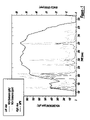
FIG. 1 is a graph showing NOx production of a vehicle during a drive cycle;
FIG. 2 is a block diagram of an engine in which the invention is used to advantage;
FIGS. 3 and 5 are flowcharts illustrating control methods of the present invention;
FIG. 4 illustrates engine maps utilized in the present invention;
FIG. 6A shows intake manifold pressure required to maintain a 17:1 AFR given an amount of fuel;
FIG. 6B shows a naturally aspirated, unthrottled AFR given a desired fuel amount (MFDES);
FIGS. 7A–D show detailed engine and vehicle test data that shows how EGR Shuts off once MFDES exceeds 50 mg/stk, and how a negative time derivative of pressure marks the end of a NOx spike;
FIG. 8 shows example results utilizing the routines of FIGS. 3–5;
FIG. 9 shows a schematic of one proposed strategy, which involves injecting a significant portion of the fuel into the combustion chamber early during the compression stroke;
FIG. 10 shows predicted NOx emissions results from a simulation of the proposed strategies in Table 1;
FIGS. 11 and 12 show detailed simulation data of the engine combustion;
FIG. 13 shows predicted heat release from a simulation of the present invention;
FIG. 14 shows the rate of Pressure Rise for the simulation data;
FIG. 15 illustrates various configurations of the present invention; and
FIGS. 16 a16 f show alternative embodiments of the present invention with respect to the block diagram of FIG. 2.
DETAILED DESCRIPTION OF THE INVENTION
FIG. 1 shows NOx emissions during a transient emissions cycle of a vehicle powered by a typical turbocharged diesel engine. The Figure demonstrates that spikes in NOx emissions occur at various times during transient operation. Those spikes typically occur during hard acceleration and the primary reason for their existence is the interaction between the turbocharging system and the typical high pressure EGR system. During hard acceleration, the use of EGR is suspended in order to both divert exhaust flow through the turbine, which allows the turbocharging system to create boost, and increases air flow through the engine. However, without EGR, NOx emissions (concentration) increase dramatically. This comes at a time when the air and thus exhaust mass flow rate are very high causing NOx production to spike dramatically.
During the a typical urban driving cycle, the time in which the engine is operated under conditions that produce these spikes accounts for only about 4–5% of the total cycle time. However, approximately 30–45% of the NOx produced during the cycle comes from these NOx spikes, as illustrated in FIG. 1.
The present invention provides several methods to overcome these NOx spikes.
FIG. 2 shows an example of an internal combustions engine system. Specifically, internal combustion engine 10, comprising a plurality of cylinders, one cylinder of which is shown in FIG. 2, is controlled by electronic engine controller 12. Engine 10 includes combustion chamber 30 and cylinder walls 32 with piston 36 positioned therein and connected to crankshaft 40. Combustion chamber 30 communicates with intake manifold 44 and exhaust manifold 48 via respective intake valve 52 and exhaust valve 54.
Exhaust air/fuel ratio sensors can also be used in the present invention. For example, either a 2-state EGO sensor or a linear UEGO sensor can be used. Either of these can be placed in the exhaust manifold 48, or downstream of devices 19 a, 22, or 20.
Intake manifold 44 communicates with throttle body 64 via throttle plate 66. In one embodiment, an electronically controlled throttle can be used. In this case, the throttle can be used to throttle airflow to help drive in more EGR. In one embodiment, the throttle is electronically controlled to periodically, or continuously, maintain a specified vacuum level in manifold 44. Intake manifold 44 is also shown having fuel injector 68 coupled thereto for delivering fuel in proportion to the pulse width of signal (fpw) from controller 12. This configuration is one potential way to get a pre-mixed mixture for dual-stage combustion, as is known in the art. Fuel is delivered to fuel injector 68 by a conventional fuel system (not shown) including a fuel tank, fuel pump, and fuel rail (not shown). In the case of direct injection engines, as shown in FIG. 2, a high pressure fuel system is used such as a common rail system. However, there are several other fuel systems that could be used as well such as EUI, HEUI, etc. In the embodiment described herein, controller 12 is a conventional microcomputer, including: microprocessor unit 102, input/output ports 104, electronic memory chip 106, which is an electronically programmable memory in this particular example, random access memory 108, and a conventional data bus.
Controller 12 receives various signals from sensors coupled to engine 10, in addition to those signals previously discussed, including: measurements of inducted mass air flow (MAF) from mass air flow sensor 110 coupled to the air filter [A on FIG. 2] (note that in a diesel engine the air flow meter is typically read before the compressor, also note that the airflow sensor should be placed before the entrance point for the low pressure EGR loop); engine coolant temperature (ECT) from temperature sensor 112 coupled to cooling jacket 114; a measurement of manifold pressure (MAP) from manifold pressure sensor 205 coupled to intake manifold 44; a measurement of throttle position (TP) from throttle position sensor 117 coupled to throttle plate 66; and a profile ignition pickup signal (PIP) from Hall effect sensor 118 coupled to crankshaft 40 indicating and engine speed (N). (Further, controller 12 receives a measurement of manifold temperature (Te) from sensor 76. Alternatively, sensor 76 can provide an indication of exhaust gas temperature, or catalyst temperature.) In an alternative embodiment, the temperature measured is typically into and/or out of catalyst(s) and/or particulate filters, rather than in the exhaust manifold, since there will be substantial temperature drop in the turbine.
Exhaust gas is delivered to intake manifold 44 by EGR tube 202 communicating with exhaust manifold 48. EGR valve assembly 200 is located in EGR tube 202. Stated another way, exhaust gas travels from exhaust manifold 44 first through valve assembly 200, then to intake manifold 44. EGR valve assembly 200 can then be said to be located upstream the intake manifold. There is also optionally an EGR cooler [Y in FIG. 2] placed in EGR tube 202 to cool EGR before entering the intake manifold. Cooling is typically done using engine water, but and air-to-air heat exchanged could also be used.
Pressure sensor 205 provides a measurement of manifold pressure (MAP) to controller 12. EGR valve assembly 200 has a valve position (not shown) for controlling a variable area restriction in EGR tube 202, which thereby controls EGR flow. EGR valve assembly 200 can either minimally restrict EGR flow through tube 202 or completely restrict EGR flow through tube 202. Vacuum regulator 224 is coupled to EGR valve assembly 200. Vacuum regulator 224 receives actuation signal (226) from controller 12 for controlling valve position of EGR valve assembly 200. In a preferred embodiment, EGR valve assembly 200 is a vacuum actuated valve. However, any type of flow control valve may be used such as, for example, an electrical solenoid powered valve or a stepper motor powered valve.
Also, particulate filter 20 and lean NOx catalyst 22 are shown coupled in the exhaust path downstream of compression device 19. Compression device 19 can be a turbocharger or any other such device. Device 19 has a turbine 19 a coupled in the exhaust manifold 48 and a compressor 19 b coupled in the intake manifold 44 via an intercooler [X in FIG. 2] which is typically and air-to-air heat exchanger, but could be water cooled. Turbine 19 a is typically coupled to compressor 19 b via a drive shaft 15. (This could also be a sequential turbocharger arrangement, single VGT, twin VGTs, or any other arrangement of turbochargers that could be used.)
Further, drive pedal 70 is shown, along with a driver's foot 72. Pedal position (pp) sensor 74 measures angular position of the driver actuated pedal.
Controls methods for transient NOx reduction are now described with reference to FIGS. 3–5. Generally, this method relates to anticipating the NOx spikes in order to initiate action (e.g., start using dual-stage combustion, start using dual EGR loops, etc.). Further, the method relates to recognizing the end of NOx spikes in order to discontinue this action.
Referring now to FIG. 3, a routine is described for controlling engine mode of operation in response to predicted NOx emissions from engine 10. In step 312, the routine determines a required fuel injection amount, or fuel demand (MFDES) based on a pedal position (pp), engine speed (N), and measured mass air flow (MAF). Note that this fuel demand can also be determined based on other parameters. For example, a two dimensional map of engine speed and pedal position can be used. Alternatively, a two-dimensional map of pedal position and vehicle speed can also be used. Moreover, the required fuel is based on a speed error during idle speed control conditions such as below a predetermined vehicle speed with pedal position below a specified value.
Next, in step 314, the routine calculates the manifold pressure (MAP) and the rate of change of manifold pressure (ΔMAP). In this particular embodiment, the change in manifold pressure is approximated as the difference in manifold pressure between the current sample and the previous sample. In one example, manifold pressure is measured from sensor 205. Note that the desired EGR amount and the EGR valve position for the common high pressure loop will depend on the mode of operation chosen from the routine that determines whether a NOx spike is predicted/detected/occurring.
Next, in step 320, the routine determines whether a NOx spike is predicted/determined as described in more detail below with particular reference to FIG. 5. In one particular example the routine checks the flag (spike_flg). Note that the spike_flg should be initialized to zero when the engine starts up. Different actions should be taken given the previous value of spike_flg as described herein with regard to FIG. 5. When the answer to step 320 is no, the routine continues to step 322 and uses normal engine operating modes. For example, EGR is delivered using the high pressure EGR loop and the desired fuel (MFDES) is injected as done during steady-state operation.
When the answer to step 320 is yes, the routine continues to step 324 where an alternate mode is performed to reduce NOx generation. The first step to all of the alternative NOx reduction strategies is to shut off the flow of EGR through the conventional high pressure EGR loop in order to quickly increase engine boost by maximizing the exhaust flow through the turbine. In this example, a multiple injection strategy is used to provide the desired fuel demand in such a way that a substantial portion of the fuel burns under fuel lean conditions, thus reducing NOx emissions. Alternatively, other multiple injection strategies could also be used to reduce NOx emissions. In another example, the high pressure EGR loop is shut off to maximize exhaust flow through the turbine and a low pressure EGR loop is used to deliver EGR to the intake air. Thus, according to the present invention, it is possible to reduce engine NOx generation while at the same time allowing engine boosting.
Referring now to FIG. 4, a two-dimensional map is shown where the desired EGR amount (or MAF) is determined based on the fuel demand and engine speed. Optionally, this map can be extended to take into account various engine-operating conditions such as engine coolant temperature and manifold pressure. In this case, multiple maps can be used to generate three-dimensional tables. In the particular example shown in FIG. 4, generally, as the required fuel and engine speed increase, the desired MAF increases (or the desired EGR decreases). Such an approach is typically utilized with turbocharged diesel engines that use high pressure EGR systems because the EGR increases turbo lag and displaces air, thus hampering the engine performance.
However, according to the present invention, if multiple EGR loops are utilized, at least modest levels of EGR can be scheduled even at high fuel demands thereby allowing for decreased NOx emissions, as shown in FIG. 4A.
Referring now to FIG. 5, a routine is described for determining when increased NOx emissions, such as NOx spikes, occur. First, in step 500, the routine determines whether a NOx spike was in progress by examining spike_flg.
If spike_flg=0 during step 500, then a NOx spike was not in progress and the routine determines whether a NOx spike starting condition is present. Various parameters can be used to make this determination such as, for example, whether the combustion air/fuel ratio is less than about 17:1, whether the desired fuel amount is greater than a fuel threshold (MF threshold), and/or whether the EGR amount is lower than an EGR threshold. (One could also potentially use concentration of O2, NO, CO2, soot, or other relevant specie in the exhaust, engine torque, pedal position, EGR valve position. However, the preferred method based on the data analyzed is described below with reference to FIGS. 6 & 7. It is only used to determine when the engine can no longer tolerate EGR or when the engine has decided to remove the EGR.) This is described in more detail below with particular reference to FIGS. 6 and 7. When the answer to step 510 is yes, the routine continues to step 512 and sets the spike flag (spike_flg) equal to 1 and the routine ends. If the answer to step 510 is no, the routine is terminated without changing spike_flg from its previous value of zero.
If spike_flg was equal to 1 during step 500, a NOx spike was already in progress and, in step 514, the routine determines whether a NOx ending condition is present. There are various methods for determining whether the NOx spike ending condition is present such as, for example, whether a change in manifold pressure is greater than a threshold, whether this change in pressure is present for a predetermined time, whether desired fuel amount is less than the threshold (including a small margin x), and/or whether engine load is decreasing. As described below, this determination of a NOx spike is used to dynamically select between operating modes in order to reduce tailpipe NOx emissions. Still other conditions that can be used include a rate of change of desired torque, required fuel injection amounts, pedal position, air/fuel ratio (oxygen/fuel ratio), or species such as O2, CO2 in the intake or exhaust. When the answer to step 514 is yes, the routine continues to step 516 to set the spike flag to zero and ends the routine. If the answer to step 514 is no, the spike flag remains at 1 and the routine ends.
Note that the methods described above allow for anticipation of a NOx spike, therefore giving a priori information that can be used to preset engine conditions to avoid the NOx spike generation.
As explained in FIG. 3, a spike_flg equal to 1 signals the engine to eliminate high pressure EGR to maximize exhaust flow through the turbine and operate in an alternate mode that is aimed at reducing NOx. Many of the methods used to reduce NOx emissions do so at the expense of soot and/or fuel economy. Consequently, it is typically not optimal to operate the engine under those conditions when high pressure EGR can be used to reduce NOx instead. In order to optimize utilization of the methods outlined above (and below), a method should be found to anticipate NOx spikes so as to minimize the operation of the engine using these methods. (Various ways to anticipate NOx spikes are suggested above. The preferred method is below.)
As stated earlier, NOx spikes occur because EGR and boost appear to be mutually exclusive when a typical high pressure EGR loop is used. The main reason for these NOx spikes during aggressive acceleration comes from the engine's need for air, which translates to a need for boost. When high pressure EGR is used, the flow of EGR robs the turbine used to drive the intake compressor of the energy it needs to create that boost. Consequently, high pressure EGR must be shut off during acceleration, which causes NOx emissions to increase dramatically. Thus, the onset of NOx spikes is dictated by the point at which it is decided that the engine can no longer operate without boost. FIG. 6A shows the amount of boost pressure required to maintain a 17:1 air/fuel ratio at various values fuel flow rates (MFDES) when the engine is operated without EGR. MFDES is given in mg/stroke. The fuel flow rate that coincides with atmospheric pressure represents the maximum amount of fuel that can be burned at or above a 17:1 air/fuel ratio without boost. For this case, that value is 50 mg/stroke. To view this in a different way, FIG. 6B shows the air/fuel ratio for a variety of fuel flow rates assuming no boost and no EGR. To reach air/fuel ratios higher than those on the curve, boosting is required. The Figure shows that boosting is needed to attain at least a 17:1 air/fuel ratio when MFDES is 50 mg/stroke. As stated earlier, in order to get boost, the level of EGR is usually significantly reduced or shut off given the current EGR system. FIGS. 7A–7D, and specifically FIGS. 7A–7B, show that the EGR valve does indeed close once MFDES exceeds 50 mg/strk, and that this occurrence coincides with the beginning of a NOx spike for the typical engine operation shown in FIG. 1. This is true over the entire cycle with very few exceptions. The data reveals that the closing of the EGR valve is not necessarily a reliable harbinger to a NOx spike. However, MFDES exceeding a value that creates an AFR lower than 17:1 when the engine is naturally aspirated, appears to be an extremely reliable indication that a NOx spike is imminent.
Note that a 17:1 AFR without boost or EGR was used in this case as the point at which the engine could no longer be operated without boost. This was done because, typically at that point, diesel combustion efficiency drops of due to a lack of available oxygen. However, the choice of air/fuel ratio used to decide this break point involves a tradeoff between engine performance during acceleration and NOx emissions. The quicker high pressure EGR is shut off, the shorter the turbocharger lag is and the quicker the engine accelerates, but at the expense of NOx emissions. The longer the EGR is used the lower the NOx is, but at the cost of longer turbocharger lag and poorer engine performance. Further analysis shows that the end of a NOx spike is marked by a drop in boost pressure, which is an indication that the load has decreased significantly.
FIGS. 7C–7D show a plot similar to that shown in FIGS. 7A–7B, but with the boost pressure overlayed on the graph. The Figure shows that the end of the NOx spikes occurs 1 or 2 seconds after the time derivative of the boost pressure becomes negative.
One aspect of the present invention is based on using the information described above to predict the start and end of a NOx spike using readily available engine parameters. This information leads to the following criterion for the particular engine selected:
    • A NOx spike begins when the fuel demand (MFDES) increases above a value at which the air requirement of the engine exceeds what can be achieved without boost (based on a minimum air/fuel ratio of, for example, 17:1). This will signify the point where either additional or alternative steps should be taken to enable simultaneous NOx control and boosting.
    • When a NOx spike is in progress, the signal that the spike is over should not be sought until the fuel demand drops below a value that is equal to or somewhat less (2–3 mg less) than that used to signify the start of the NOx spike. Using a value somewhat less than that used in the previous step may help prevent choppy engine operation caused by jumping in and out of modes of operation too frequently.
    • A NOx spike ends when the manifold air pressure (boost) has decreased over the last 1–2 seconds. This signifies a drop in the airflow and engine load.
Note that this data is merely an example of the criteria that can be selected for use in the flow charts and routines described above herein with particular reference to FIGS. 3–5.
FIG. 8 shows the degree of success that can be achieved in determining the time and duration of NOx spikes using these guidelines. However, as described above, various combinations of parameters can be used, with varying accuracy.
The strategy described herein could facilitate drastic reductions in NOx during transient cycles. The extent of the reduction would depend on the alternative mode of operation used to reduce NOx emissions without the use of high pressure EGR. Some possible alternate modes of operation are:
  • 1. To immediately remove most or all EGR and use dual-stage combustion. Using this method and assuming that a 70% NOx reduction would be obtained during that time (as projected from combustion simulations), it is projected that a 33% reduction in FTP cycle NOx emissions would result. However, it may be possible to achieve even further reduction by combining the dual stage combustion and corresponding control routines with EGR.
  • 2. To remove EGR and use other split injection strategies aimed at reducing NOx emissions. Split main injection has been shown in the SAE literature (see SAE 960633).
  • 3. Continue using EGR at high to moderate levels and use Electric Assisted Boosting to increase intake pressure. No projections of the NOx benefit for this method have been developed. (Note, however, that this approach has a potential drawback in that it will reduce and ultimately eliminate the EGR driving force.)
  • 4. Have both low pressure and high pressure EGR loops on the engine. Close the high pressure EGR loop during NOx spikes and use the low pressure EGR loop to provide a base level of EGR. That level may be smaller than that used during steady state in order to avoid displacing too much air. (Even a small level of EGR would reduce NOx better during acceleration since the high pressure EGR valve would have to be shut anyway.)
Next, a detailed explanation of the dual stage combustion is described. This is a method for diesel combustion in which combustion occurs in two separate stages, lean pre-mixed combustion and normal diesel combustion. Lean pre-mixed combustion is accomplished by introducing a significant portion of the fuel either into the combustion chamber very early in the compression stroke through one or a series of pilot injections or into the intake manifold during induction. The early introduction of this fuel gives it enough time to mix with the air and form a lean (and potentially homogeneous) mixture that ignites due to the increased temperature during compression, potentially in HCCI-like combustion. The remainder of the fuel is injected in any number of injection events to produce standard diesel combustion. This method of combustion obtains low NOx emissions with very little smoke penalty.
Because its formation rates increase with temperature, NOx emissions are primarily produced in an internal combustion engine in combustion regions where the local equivalence ratio is close to stoichiometric. Soot is formed in high temperature rich regions of the combustion chamber. Diesel combustion is a process in which fuel progresses through both of these regions, despite the fact that the overall equivalence ratio is usually fairly lean. Most of the fuel injected in a diesel engine is initially broken down under locally rich equivalence ratios either in the premixed burn stage or in the fuel-rich premixed flame. These regions mainly produce CO, UHC, and soot precursors. That broken down fuel ultimately proceeds through a thin diffusion flame that exists at or near stoichiometric equivalence ratios, where complete products are produced and full heat release is achieved and NOx is produced (see SAE 970873).
The present invention includes a combustion strategy designed to burn significant portion of the fuel under lean conditions, thus avoiding both NOx and soot production.
FIG. 9 shows a schematic of the proposed strategy, which involves injecting a significant portion of the fuel into the combustion chamber early during the compression stroke (first pulse), thus enabling that fuel to mix with air and burn under lean air/fuel equivalence ratios. The remaining fuel is injected near top dead center (TDC) and burned normally (second pulse). The fuel that is injected during the first pulse is burned under lean conditions and produces an insignificant amount of NOx and soot emissions. The heat release from that fuel serves to heat the contents of the combustion chamber. This shortens the ignition delay of the second pulse, thus reducing both NOx emissions and combustion noise.
This concept was tested using simulations of the closed cycle portion of a diesel engine (IVC to EVO). Simulations were conducted for a single engine operating condition: 1500 rpm, 5 bar BMEP (˜30 mg/stroke). Thirteen different injection schemes were assessed. The baseline case was a single injection pulse delivering 100% of the fuel starting at +3.2 CA ATDC. The basic injection parameters defining this baseline case and the other twelve cases are shown in Table 1.
TABLE 1
Simulation Injection Strategies
Case 1st Inj. Qty. Dwell SOI Main Dwell
Number (% of total) (CA) (CA ATDC) (CA)
1 0 N/A +3.2 N/A
2 7 10 +3.2 10
3 7 20 +3.2 20
4 7 40 +3.2 40
5 7 90 +3.2 90
6 21 10 +3.2 10
7 21 20 +3.2 20
8 21 40 +3.2 40
9 21 90 +3.2 90
10 49 10 +3.2 10
11 49 20 +3.2 20
12 49 40 +3.2 40
13 49 90 +3.2 90
FIG. 10 shows the NOx emissions results (simulated NOx emissions with pre-injection) for this study. The Figure shows that for all cases, except that of relatively close-coupled, large-quantity pilot injection, a substantial NOx reduction (50–70%) was achieved using early fuel injection.
The simulations suggest that two major mechanisms contribute to the decrease in NOx emissions using pre-injection. First, the fuel that is pre-injected has time to mix with air and create a lean mixture before combustion. This can be seen in FIG. 11, which shows a snapshot of the in-cylinder equivalence ratio just prior to main fuel injection in which 21% of the fuel is pre-injected about 90 CA before TDC. This lean mixture burns at very low temperatures (see FIG. 12), thus producing low NOx; it also produces low soot emissions because of the abundance of oxygen. I.e., FIG. 11 shows the lean combustion of pre-injected fuel, and FIG. 12 shows the low temperature combustion of pre-injected fuel.
The second factor contributing to NOx reduction is a decrease in the ignition delay caused by the addition of heat in the combustion chamber. The amount of fuel injected during ignition delay has a strong correlation with the amount of NOx produced by the engine. FIG. 13 compares the heat release rate of the baseline (single injection) case with that of two cases in which 21% of the fuel was pre-injected. The Figure illustrates that early fuel injection significantly reduces ignition delay. This results in a significant reduction in NOx emissions. The Figures also illustrates the ignition delay.
This method of NOx reduction has an added benefit to noise, much like pilot injection. FIG. 14 compares the rate of change of in-cylinder pressure, a quantity for which the maximum value is directly related to the combustion noise, for three cases:
  • (1) Single injection.
  • (2) Close-coupled pre-injection of a small quantity of fuel.
  • (3) Pre-injection of a moderate quantity of fuel early during compression stroke.
The Figure shows that noise is reduced significantly from a single injection case when part of the fuel is injected early in the compression stroke. The Figure also shows that this noise reduction is comparable to that of what should be representative of a conventional pilot injection.
The following Figures and description relate to various types of EGR systems that can be used to solve the EGR-boost problem described above. Some of these are alternative EGR systems in which all or part of the EGR flows from the exhaust line after a diesel particulate filter (low pressure) to either a point before the compressor (low pressure) or to the intake manifold (high pressure). Since the EGR gases flowing through these lines would still flow through the turbine, this EGR would not diminish the performance of the turbine. Thus, the turbine would be able to spin up quickly even with modest or possibly high levels of EGR. For cases in which only some of the EGR flows through this low pressure loop, a second EGR loop, one that is identical to a conventional EGR loop, is used. In this case, only the low pressure loop is used when trying to accelerate.
FIG. 15 shows a schematic view of engine 10, including compressor 19 b, turbine 19 a, intake manifold 44, exhaust manifold 48, particulate filter 20, lean NOx catalyst 22, and intercooler 1500. For reference, points 1–7 are also labeled to facilitate the description below.
A typical EGR system takes exhaust gas from the exhaust manifold (5) and plumbs it back into the intake manifold (4). Such a system is shown in FIG. 2. For some cases, the flow rate of EGR is too high for the EGR plumbing capacity at natural pressure differences, thus requiring the use of an intake throttle to depress the inlet air pressure and drive more EGR. EGR that flows through this loop does not flow through the turbine, thus starving the turbine for input energy. The following shows the benefits and consequences of using several alternate EGR systems. These systems were narrowed from a host of possibilities according to the following criteria:
    • One should not pump dirty or sooty exhaust gas.
    • One should not put dirty or sooty exhaust gas into the compressor.
      Possible EGR Systems given the above criteria:
  • 1. 5 to 4—Common High Pressure Loop (see FIG. 2)
  • 2. 7 to 4—Low Pressure to High Pressure (see FIG. 16 a)
  • 3. 7 to 1—Low Pressure Loop (see FIG. 16 b)
  • 4. 5 to 4 & 7 to 4—dual-loop EGR system (see FIG. 16 c)
  • 5. 5 to 4 & 7 to 1—dual-loop EGR system (see FIG. 16 d)
  • 6. 7 to 2—Low Pressure to High Pressure using intercooler for cooling EGR (see FIG. 16 e)
  • 7. 5 to 4 & 7 to 2—dual-loop EGR system using intercooler for cooling EGR (see FIG. 16 f)
    Note that some of the equipment in the EGR loops described herein is optional such as coolers, throttles, and pumps.
    EGR System #1: 5 to 4 (See FIG. 2)
As stated, this is the basic EGR system, described in FIG. 2, which is suitable for use with the present invention, especially if the multiple injection strategy described above is utilized. This system allows EGR flow without pumping (especially at light loads), and a low filling/purging volume (quick response). However, it also potentially has a bulk flow pumping loss for throttling, dirty EGR (durability), less flow through the turbine-turbo lag, no EGR during transients—NOx control problem, and coordinated control with EGR valve and intake throttle.
EGR System #2: 7 to 4 (See FIG. 16 a)
In this system, EGR is brought from a point after the diesel particulate filter to the intake manifold using an air pump (not shown). An additional cooler (not shown) is placed somewhere in the EGR loop in order to cool the EGR before entering the combustion chamber. The flow rate of EGR is controlled using a valve. Such a system is also shown in FIG. 16 a. In particular, exhaust is routed from manifold 48 to the turbine 19 a. From there, it passes to particulate filter 20 and lean NOx catalyst 22. Exhaust gas downstream of device 22 is then routed to pump Zb, and cooler Yb, before passing through the valve 200 b and entering manifold 44.
This system provides minimal dirty EGR (better durability), minimal bulk flow pumping losses (intake throttle can be eliminated if desired), all exhaust gas flows through the turbine (improved turbo response), low filling/purging volume (quick response), EGR can be used during transients—NOx control, and a simpler control system (if not using ITH to control EGR). However, all of the EGR is pumped (high pressure, high mass flow), all exhaust flows through DPF—increased back pressure, and there is a longer EGR plumbing loop.
EGR System #3: 7 to 1 (See FIG. 16 b)
In this system, EGR is brought from a point after the diesel particulate filter to a point before the compressor using an air pump or a venturi (not shown). A cooler (Ya) is also placed in the EGR loop in order to cool the EGR before entering the compressor. The flow rate of EGR is controlled using a valve such as valve 200. An optional pump Za is also shown. An optional intake throttle 117 is also shown.
Such a system gives minimal dirty EGR (better durability), minimal bulk flow pumping losses—(intake throttle can be eliminated), all exhaust gas flows through the turbine (improved turbo response), potential to use a venturi to pump EGR, EGR during transient—NOx control, and a potentially simpler control system (if throttle eliminated). Further, there is potential for better EGR distribution/mixing. However, there may be a need for a pump, all exhaust flows through DPF—increased back pressure, there is a longer EGR plumbing loop, and there is an increased filling/purging volume—degraded transient response.
EGR System #4: 5 to 4 & 7 to 4 (See FIG. 16 c)
In this system, shown in FIG. 2, two EGR loops are used. One EGR loop connects the exhaust, manifold to the intake manifold. The other takes exhaust gases from a point after the DPF and pumps the into the intake manifold using an air pump. When the vehicle is not accelerating, the first EGR loop is used to its fullest extent, and the second loop is used to supplement the EGR flow to avoid using the intake throttle. When the vehicle is trying to accelerate (or when a NOx spike is predicted), the first EGR valve is shut to maximize the exhaust flow through the turbine, thus improving transient response of the engine. The second loop is used to supply a base amount of EGR to control NOx emissions. Coolers (not shown) and pumps (not shown) can be present in both EGR loops to reduce EGR temperature.
This system allows partially free EGR, minimal bulk flow pumping losses (potential to eliminate intake throttle), EGR during transient—NOx control, more exhaust flow through turbine during normal operation—less turbo lag, all exhaust flows through the turbine during transient—better response, and low filling/purging volume (quick response). However, there may be durability issues. Further, this system may require pumping EGR (high pressure, low mass flow), added cost, longer EGR plumbing, coordinated control between the loops, and slightly higher flow through DPF (increased back pressure).
EGR System #5: 5 to 4 & 7 to 1 (see FIG. 16 d)
This system includes two EGR loops. One EGR loop connects the exhaust manifold to the intake manifold, like those used currently. The other takes exhaust gases from a point after the DPF and pumps it to a point before the compressor using either an air pump or a venturi. When the vehicle is not accelerating (no NOx spike predicted), the first EGR loop is used as much as is needed, and the second loop is used to supplement the EGR flow if required, thus avoiding the use of the intake throttle. When the vehicle is trying to accelerate (or a NOx spike is predicted), the first EGR valve is shut to maximize the exhaust flow through the turbine, thus improving transient response of the engine. The second loop is used to supply a base amount of EGR to the engine to control NOx emissions. Optional Coolers (Y) cab be present in both EGR loops to reduce EGR temperature. Further, optional pumps (Z) could also be used.
This system allows partially free EGR, minimal bulk flow pumping losses (possibility to eliminate intake throttle), EGR during transient—NOx control, more exhaust flows through turbine during normal operation—less turbo lag, all exhaust flows through the turbine during transient—better response, low filling/purging volume for most EGR flow (quick response), some of EGR, most during transient operation, will be well mixed, and likely to use a venturi instead of an air pump (low pressure, low mass flow). However, in additional to durability, there may be added cost due to the dual loops, longer EGR plumbing, coordinated control, and slightly higher flow through DPF (increased back pressure).
The inventors here have conducted tests both on an engine dynamometer and in a vehicle and have found a benefit to using this loop to NOx (˜10–12% reduction) without sacrificing engine performance or fuel economy. In fact, there may even be a fuel economy benefit to using this system over the convention system, system #1), depending on the engine and system configuration.
EGR System #6: 7 to 2 (See FIG. 16 e)
This system has essentially the same benefits and disadvantages as EGR system #3, with only two exceptions. First, the pressure just after the compressor is slightly higher than in the intake manifold, therefore flowing EGR in this loop would be more difficult. Second, using the intercooler to cool the EGR with the intake air would introduce a potential cost save since it would eliminate the need for an EGR cooler. An optional pump Zc, optional intercooler Yc, are shown routing exhaust gas via line 202 c upstream of the device 19 b. A vacuum regulator 224 c is also shown providing an EGR pressure signal (EGRPc), along with an EGR valve 200 c. Note that System # 6 can be considered as a possible variation of the low to high pressure EGR loop configuration of system # 2.
EGR System #7: 5 to 4 & 7 to 2 (See FIG. 16 f)
This system has essentially the same benefits and disadvantages as EGR system # 5, with only two exceptions. First, the pressure just after the compressor is slightly higher than in the intake manifold, therefore flowing EGR in this loop would be more difficult. Second, using the intercooler to cool the EGR with the intake air would introduce a potential cost save since it would eliminate the need for an EGR cooler. Note that System # 7 can be considered as a possible variation of system #4.
Finally, note that systems 4, 5, and 7 are especially suited for use with the strategy described above herein. Thus, according to the present invention, it is possible to use a dual loop EGR system to reduce NOx. In one example, the two EGR loops are each adjusted via valves to control the amount of EGR based on engine operating conditions. In some conditions, both EGR loops are used, and in other conditions, only one of the loops it utilized. Further still, in other example, neither loop is used.
In one specific example described above, at least two operating modes are utilized. A first mode is used where two EGR loops are utilized (both a high pressure loop and a low pressure loop). In this case, the lop pressure loop is used to put in a low level of EGR while the high pressure loops is used to control EGR amount in total (or airflow). A second mode uses only the low pressure EGR loop to maximize the mass flow through the turbine.
In this way, it is possible to minimize NOx emissions, even during tip-in NOx spikes.
This concludes the detailed description. As noted above herein, there are various alterations that can be made to the present invention.

Claims (4)

1. A system for an engine having an intake and exhaust manifold, the engine having a compression device coupled with a first portion coupled to the intake and a second portion coupled to the exhaust manifold of the engine, the system comprising:
a first exhaust gas recirculation system having a first end coupled to the exhaust manifold upstream of the second portion of the compression device and a second end coupled to the intake manifold downstream of the first portion compression device, said first system also having a first valve that adjusts a first flow amount from the exhaust manifold to the intake manifold; said first system having an exhaust gas recirculation (EGR) cooler between said first valve and said exhaust manifold and
a second exhaust gas recirculation system having a first end coupled downstream of the second portion of the compression device and a second end coupled upstream of the first portion of the compression device, said second system also having a second valve that adjusts a second flow amount from the exhaust to the intake, where said first valve only adjusts flow from said first exhaust gas recirculation system.
2. The system recited in claim 1 further comprising a controller electrically coupled to said first and second valve.
3. A system for an engine having an intake and exhaust manifold, the engine having a compression device coupled with a first portion coupled to the intake and a second portion coupled to the exhaust manifold of the engine, the system comprising:
a first exhaust gas recirculation system having a first end coupled to the exhaust manifold upstream of the second portion of the compression device and a second end coupled to the intake manifold downstream of the first portion compression device, said first system also having a first valve that adjusts a first flow amount from the exhaust manifold to the intake manifold; said first system having an exhaust gas recirculation (EGR) cooler between said first valve and said exhaust manifold and
a second exhaust gas recirculation system having a first end coupled downstream of the second portion of the compression device and a second end coupled upstream of the first portion of the compression device, said second system also having a second valve that adjusts a second flow amount from the exhaust to the intake,
a controller electrically coupled to said first and second valve,
and wherein said controller determines engine operating conditions, and actuates both said first and second valve during a first mode to enable exhaust gas recirculation flow through both exhaust gas recirculation systems, and actuates only said second valve during a second mode based on said determined operating conditions to enable exhaust gas recirculation flow only through the second exhaust gas recirculation system.
4. A system for an engine having an intake and exhaust manifold, the engine having a compression device coupled with a first portion coupled to the intake and a second portion coupled to the exhaust manifold of the engine, the system comprising:
a first exhaust gas recirculation system having a first end coupled to the exhaust manifold upstream of the second portion of the compression device and a second end coupled to the intake manifold downstream of the first portion compression device, said first system also having a first valve that adjusts a first flow amount from the exhaust manifold to the intake manifold; said first system having an exhaust gas recirculation (EGR) cooler between said first valve and said exhaust manifold and
a second exhaust gas recirculation system having a first end coupled downstream of the second portion of the compression device and a second end coupled upstream of the first portion of the compression device, said second system also having a second valve that adjusts a second flow amount from the exhaust to the intake, where said second valve only adjusts flow from said second exhaust gas recirculation system.
US10/961,005 2003-02-03 2004-10-07 System and method for reducing NOx emissions during transient conditions in a diesel fueled vehicle with EGR Expired - Lifetime US7273045B2 (en)

Priority Applications (1)

Application Number Priority Date Filing Date Title
US10/961,005 US7273045B2 (en) 2003-02-03 2004-10-07 System and method for reducing NOx emissions during transient conditions in a diesel fueled vehicle with EGR

Applications Claiming Priority (2)

Application Number Priority Date Filing Date Title
US10/248,634 US6820599B2 (en) 2003-02-03 2003-02-03 System and method for reducing Nox emissions during transient conditions in a diesel fueled vehicle with EGR
US10/961,005 US7273045B2 (en) 2003-02-03 2004-10-07 System and method for reducing NOx emissions during transient conditions in a diesel fueled vehicle with EGR

Related Parent Applications (1)

Application Number Title Priority Date Filing Date
US10/248,634 Division US6820599B2 (en) 2003-02-03 2003-02-03 System and method for reducing Nox emissions during transient conditions in a diesel fueled vehicle with EGR

Publications (2)

Publication Number Publication Date
US20050045163A1 US20050045163A1 (en) 2005-03-03
US7273045B2 true US7273045B2 (en) 2007-09-25

Family

ID=32735341

Family Applications (3)

Application Number Title Priority Date Filing Date
US10/248,634 Ceased US6820599B2 (en) 2003-02-03 2003-02-03 System and method for reducing Nox emissions during transient conditions in a diesel fueled vehicle with EGR
US10/961,005 Expired - Lifetime US7273045B2 (en) 2003-02-03 2004-10-07 System and method for reducing NOx emissions during transient conditions in a diesel fueled vehicle with EGR
US12/568,988 Expired - Lifetime USRE42609E1 (en) 2003-02-03 2009-09-29 System and method for reducing NOx emissions during transient conditions in a diesel fueled vehicle with EGR

Family Applications Before (1)

Application Number Title Priority Date Filing Date
US10/248,634 Ceased US6820599B2 (en) 2003-02-03 2003-02-03 System and method for reducing Nox emissions during transient conditions in a diesel fueled vehicle with EGR

Family Applications After (1)

Application Number Title Priority Date Filing Date
US12/568,988 Expired - Lifetime USRE42609E1 (en) 2003-02-03 2009-09-29 System and method for reducing NOx emissions during transient conditions in a diesel fueled vehicle with EGR

Country Status (2)

Country Link
US (3) US6820599B2 (en)
DE (1) DE102004004534B4 (en)

Cited By (13)

* Cited by examiner, † Cited by third party
Publication number Priority date Publication date Assignee Title
US7400955B2 (en) * 2006-04-05 2008-07-15 Robert Bosch Gmbh Procedure to diagnose a fuel tank ventilation system and device to implement the procedure
US20090132153A1 (en) * 2005-12-20 2009-05-21 Borgwarner Inc. Controlling exhaust gas recirculation in a turbocharged compression-ignition engine system
US20090223221A1 (en) * 2006-11-06 2009-09-10 Tomomi Onishi Exhaust gas recirculation system for internal combustion engine and method for controlling the same
US20100000500A1 (en) * 2006-09-29 2010-01-07 Toyota Jidosha Kabushiki Kaisha Egr system for internal combustion engine and method for controlling the same
US20100031939A1 (en) * 2006-10-25 2010-02-11 Toyota Jidosha Kabushiki Kaisha Exhaust gas recirculation apparatus for an internal combustion engine
US20100101226A1 (en) * 2007-03-28 2010-04-29 Borgwarner Inc. Controlling exhaust gas recirculation in a turocharged compression-ignition engine system
US20110162628A1 (en) * 2010-07-20 2011-07-07 Ford Global Technologies, Llc Compensation For Oxygenated Fuel Use In A Diesel Engine
US20110162626A1 (en) * 2010-08-05 2011-07-07 Ford Global Technologies, Llc Coordination of HP and LP EGR
US20110166767A1 (en) * 2010-07-20 2011-07-07 Ford Global Technologies, Llc Compensation for oxygenated fuels in a diesel engine
US20110174263A1 (en) * 2010-07-29 2011-07-21 Ford Global Technologies, Llc Method and system for controlling fuel usage
USRE42609E1 (en) 2003-02-03 2011-08-16 Ford Global Technologies, Llc System and method for reducing NOx emissions during transient conditions in a diesel fueled vehicle with EGR
US9909517B2 (en) 2015-11-23 2018-03-06 Cummins Inc. Mult-mode controls for engines systems including SCR aftertreatment
US9976499B2 (en) 2010-09-23 2018-05-22 General Electric Company Engine system and method

Families Citing this family (41)

* Cited by examiner, † Cited by third party
Publication number Priority date Publication date Assignee Title
BRPI0416555A (en) * 2003-11-12 2007-08-21 Mack Trucks turbocharger overload detection
US7117843B2 (en) * 2004-10-07 2006-10-10 International Engine Intellectual Property Company, Llc Emission reduction in a diesel engine using an alternative combustion process and a low-pressure EGR loop
DE102005013977B4 (en) * 2005-03-26 2020-09-03 Ford Global Technologies, Llc Exhaust gas recirculation system for a motor vehicle and method for setting the exhaust gas recirculation rate in a gas recirculation system
US7168250B2 (en) * 2005-04-21 2007-01-30 International Engine Intellectual Property Company, Llc Engine valve system and method
US7063076B1 (en) 2005-05-16 2006-06-20 Detroit Diesel Corporation Method of smoke limiting engine
DE102005026503A1 (en) * 2005-06-09 2006-12-14 Robert Bosch Gmbh Method and device for controlling an internal combustion engine
GB2434406A (en) * 2005-08-25 2007-07-25 Ford Global Tech Llc I.c. engine exhaust gas recirculation (EGR) system with dual high pressure and low pressure EGR loops
US7367188B2 (en) * 2006-07-28 2008-05-06 Ford Global Technologies, Llc System and method for diagnostic of low pressure exhaust gas recirculation system and adapting of measurement devices
US7284366B2 (en) * 2005-09-28 2007-10-23 Ford Global Technologies, Llc System and method for operating an engine having an exhaust gas recirculation system
DE102005056955A1 (en) * 2005-11-30 2007-05-31 Volkswagen Ag Internal combustion engine, e.g. diesel engine with low pressure exhaust gas recycling, has exhaust gas recycle valve and exhaust gas flap that are arranged either integrated in particle filter or combined behind particle filter
US8630787B2 (en) * 2005-12-20 2014-01-14 Borgwarner Inc. Controlling exhaust gas recirculation in a turbocharged engine system
JP4240045B2 (en) * 2006-03-23 2009-03-18 トヨタ自動車株式会社 Exhaust gas purification system for internal combustion engine
US7277790B1 (en) 2006-04-25 2007-10-02 Ut-Battelle, Llc Combustion diagnostic for active engine feedback control
US20070261406A1 (en) * 2006-05-12 2007-11-15 General Electric Company Systems and methods of reducing NOx emissions in internal combustion engines
US7493884B2 (en) * 2006-10-12 2009-02-24 Caterpillar Inc. Method and system for reducing pollutant emissions of an engine
US8359837B2 (en) * 2006-12-22 2013-01-29 Cummins Inc. Temperature determination and control of exhaust aftertreatment system adsorbers
JP4793381B2 (en) * 2007-12-07 2011-10-12 トヨタ自動車株式会社 Fuel injection control device for internal combustion engine
US8176736B2 (en) * 2008-03-21 2012-05-15 Cummins Inc. EGR apparatuses, systems, and methods
US7770565B2 (en) * 2008-04-08 2010-08-10 Cummins Inc. System and method for controlling an exhaust gas recirculation system
US20100006073A1 (en) * 2008-07-10 2010-01-14 Jayant Jatkar Increasing effeciency of internal combustion engines to increase mileage of vehicles
DE102009057799A1 (en) * 2009-12-10 2011-06-16 Volkswagen Ag Motor vehicle i.e. diesel vehicle, has return line downstream to compressors to supply gas into suction channel, and exhaust gas recirculation cooler attached to line, where specific percent of gas is supplied to cooler for cooling
US8516816B2 (en) * 2010-06-02 2013-08-27 Ford Global Technologies, Llc Avoidance of coolant overheating in exhaust-to-coolant heat exchangers
JP5028509B2 (en) * 2010-06-16 2012-09-19 本田技研工業株式会社 EGR control device for internal combustion engine
JP5075229B2 (en) * 2010-06-18 2012-11-21 本田技研工業株式会社 EGR control device for internal combustion engine
FR2962164B1 (en) * 2010-06-30 2012-12-07 Valeo Systemes Thermiques DEVICE FOR RECIRCULATING EXHAUST GAS OF A MOTOR VEHICLE ENGINE
US9181904B2 (en) * 2010-08-10 2015-11-10 Ford Global Technologies, Llc Method and system for exhaust gas recirculation control
KR101753402B1 (en) * 2011-01-24 2017-07-03 두산인프라코어 주식회사 an Exhaust Gas Recirculation Apparatus Control method for a Construction Heavy Equipment
FR2975136B1 (en) * 2011-05-13 2014-11-21 Continental Automotive France METHOD FOR DETERMINING THE FUEL QUANTITY EXCEEDING AN INJECTOR
US9074542B2 (en) * 2011-07-20 2015-07-07 General Electric Company Method and system for controlling an engine during tunneling operation
US9222426B2 (en) * 2012-02-17 2015-12-29 Ford Global Technologies, Llc Transient air flow control
FR2991725B1 (en) * 2012-06-11 2017-12-15 Valeo Systemes De Controle Moteur ASSEMBLY COMPRISING A THERMAL MOTOR AND AN ELECTRIC COMPRESSOR
US9255550B2 (en) * 2013-03-08 2016-02-09 GM Global Technology Operations LLC Emission system and method of selectively directing exhaust gas and air within an internal combustion engine
JP6413562B2 (en) * 2014-09-30 2018-10-31 三菱自動車工業株式会社 Engine control device
JP6413563B2 (en) * 2014-09-30 2018-10-31 三菱自動車工業株式会社 Engine control device
US9724734B2 (en) 2015-01-30 2017-08-08 Kärcher North America, Inc. High efficiency hot water pressure washer
DE102016203061A1 (en) 2016-02-26 2017-08-31 Robert Bosch Gmbh Method and device for operating an internal combustion engine with exhaust gas recirculation
JP6647160B2 (en) * 2016-07-05 2020-02-14 本田技研工業株式会社 Vehicle control device
US10920687B2 (en) 2016-11-15 2021-02-16 Cummins Inc. Spark ignition engine control with exhaust manifold pressure sensor
DE102019204810A1 (en) 2019-04-04 2020-10-08 Hyundai Motor Company Control device and method for controlling the exhaust gas emissions of a motor vehicle
US11852115B2 (en) 2019-08-09 2023-12-26 Arctic Cat Inc. Engine control system and methods
US11629661B1 (en) 2021-10-12 2023-04-18 National Technology & Engineering Solutions Of Sandia, Llc Low soot stoichiometric compression-ignition combustion

Citations (29)

* Cited by examiner, † Cited by third party
Publication number Priority date Publication date Assignee Title
US4215550A (en) 1977-02-17 1980-08-05 Motoren- Und Turbinen-Union Friedrichshafen Gmbh Supercharged internal combustion engine and method of operation thereof
DE4007516A1 (en) 1990-03-09 1991-09-12 Kloeckner Humboldt Deutz Ag Reduction of exhaust pollution of diesel engine - by fitting particle filter and oxidising catalyser
US5119780A (en) 1991-06-11 1992-06-09 Southwest Research Institute Staged direct injection diesel engine
JPH0571428A (en) 1991-09-10 1993-03-23 Yanmar Diesel Engine Co Ltd Exhaust gas reflux device of diesel engine
US5203311A (en) * 1990-11-06 1993-04-20 Mazda Motor Corporation Exhaust gas recirculation system for an internal combustion engine
US5261366A (en) 1993-03-08 1993-11-16 Chrysler Corporation Method of fuel injection rate control
US5341300A (en) 1991-09-18 1994-08-23 Mitsubishi Denki Kabushiki Kaisha Trouble diagnosis device and method for exhaust gas return control device
US5440880A (en) 1994-05-16 1995-08-15 Navistar International Transportation Corp. Diesel engine EGR system with exhaust gas conditioning
US5771868A (en) 1997-07-03 1998-06-30 Turbodyne Systems, Inc. Turbocharging systems for internal combustion engines
US5806308A (en) 1997-07-07 1998-09-15 Southwest Research Institute Exhaust gas recirculation system for simultaneously reducing NOx and particulate matter
US5927075A (en) 1997-06-06 1999-07-27 Turbodyne Systems, Inc. Method and apparatus for exhaust gas recirculation control and power augmentation in an internal combustion engine
JPH11210449A (en) * 1998-01-29 1999-08-03 Mazda Motor Corp Engine with turbo supercharger
US5979398A (en) 1997-06-24 1999-11-09 Toyota Jidosha Kabushiki Kaisha Compression-ignition type engine
US6062026A (en) 1997-05-30 2000-05-16 Turbodyne Systems, Inc. Turbocharging systems for internal combustion engines
US6082325A (en) 1997-11-13 2000-07-04 Daimlerchrysler Ag Process and system for operating a diesel engine
US6205785B1 (en) 1999-07-21 2001-03-27 Caterpillar Inc. Exhaust gas recirculation system
US6240721B1 (en) * 1998-09-17 2001-06-05 Toyota Jidosha Kabushiki Kaisha Internal combustion engine and method for controlling an internal combustion engine
US6276334B1 (en) 1998-02-23 2001-08-21 Cummins Engine Company, Inc. Premixed charge compression ignition engine with optimal combustion control
US6301888B1 (en) 1999-07-22 2001-10-16 The United States Of America As Represented By The Administrator Of The Environmental Protection Agency Low emission, diesel-cycle engine
US6301887B1 (en) 2000-05-26 2001-10-16 Engelhard Corporation Low pressure EGR system for diesel engines
US6338245B1 (en) * 1999-09-17 2002-01-15 Hino Motors, Ltd. Internal combustion engine
US6427436B1 (en) * 1997-08-13 2002-08-06 Johnson Matthey Public Limited Company Emissions control
US6435166B1 (en) 1999-06-16 2002-08-20 Komatsu Ltd. Exhaust gas recirculation device and control method thereof
US20020112478A1 (en) * 1998-04-16 2002-08-22 Frank Pfluger Turbocharged internal combustion engine
US6470866B2 (en) 2000-01-05 2002-10-29 Siemens Canada Limited Diesel engine exhaust gas recirculation (EGR) system and method
US6470864B2 (en) * 2000-03-27 2002-10-29 Mack Trucks, Inc. Turbocharged engine with exhaust gas recirculation
US6516787B1 (en) 2002-05-08 2003-02-11 Caterpillar Inc Use of exhaust gas as sweep flow to enhance air separation membrane performance
US6651432B1 (en) * 2002-08-08 2003-11-25 The United States Of America As Represented By The Administrator Of The Environmental Protection Agency Controlled temperature combustion engine
US20040079079A1 (en) * 2002-10-23 2004-04-29 Martin Steven P. Charge air condensation collection system for engines with exhaust gas recirculation

Family Cites Families (6)

* Cited by examiner, † Cited by third party
Publication number Priority date Publication date Assignee Title
DE19618868C2 (en) * 1996-05-10 1998-07-02 Daimler Benz Ag Internal combustion engine with an exhaust gas recirculation system
US6354084B1 (en) * 1999-08-20 2002-03-12 Cummins Engine Company, Inc. Exhaust gas recirculation system for a turbocharged internal combustion engine
JP2002276405A (en) * 2001-03-19 2002-09-25 Isuzu Motors Ltd Exhaust emission control device of diesel engine
JP4134678B2 (en) 2002-10-23 2008-08-20 トヨタ自動車株式会社 Exhaust gas recirculation device for an internal combustion engine with a supercharger
EP1689997B1 (en) 2002-11-13 2014-12-17 Honeywell International Inc. Dual and hybrid egr systems for use with turbocharged engine
US6820599B2 (en) 2003-02-03 2004-11-23 Ford Global Technologies, Llc System and method for reducing Nox emissions during transient conditions in a diesel fueled vehicle with EGR

Patent Citations (29)

* Cited by examiner, † Cited by third party
Publication number Priority date Publication date Assignee Title
US4215550A (en) 1977-02-17 1980-08-05 Motoren- Und Turbinen-Union Friedrichshafen Gmbh Supercharged internal combustion engine and method of operation thereof
DE4007516A1 (en) 1990-03-09 1991-09-12 Kloeckner Humboldt Deutz Ag Reduction of exhaust pollution of diesel engine - by fitting particle filter and oxidising catalyser
US5203311A (en) * 1990-11-06 1993-04-20 Mazda Motor Corporation Exhaust gas recirculation system for an internal combustion engine
US5119780A (en) 1991-06-11 1992-06-09 Southwest Research Institute Staged direct injection diesel engine
JPH0571428A (en) 1991-09-10 1993-03-23 Yanmar Diesel Engine Co Ltd Exhaust gas reflux device of diesel engine
US5341300A (en) 1991-09-18 1994-08-23 Mitsubishi Denki Kabushiki Kaisha Trouble diagnosis device and method for exhaust gas return control device
US5261366A (en) 1993-03-08 1993-11-16 Chrysler Corporation Method of fuel injection rate control
US5440880A (en) 1994-05-16 1995-08-15 Navistar International Transportation Corp. Diesel engine EGR system with exhaust gas conditioning
US6062026A (en) 1997-05-30 2000-05-16 Turbodyne Systems, Inc. Turbocharging systems for internal combustion engines
US5927075A (en) 1997-06-06 1999-07-27 Turbodyne Systems, Inc. Method and apparatus for exhaust gas recirculation control and power augmentation in an internal combustion engine
US5979398A (en) 1997-06-24 1999-11-09 Toyota Jidosha Kabushiki Kaisha Compression-ignition type engine
US5771868A (en) 1997-07-03 1998-06-30 Turbodyne Systems, Inc. Turbocharging systems for internal combustion engines
US5806308A (en) 1997-07-07 1998-09-15 Southwest Research Institute Exhaust gas recirculation system for simultaneously reducing NOx and particulate matter
US6427436B1 (en) * 1997-08-13 2002-08-06 Johnson Matthey Public Limited Company Emissions control
US6082325A (en) 1997-11-13 2000-07-04 Daimlerchrysler Ag Process and system for operating a diesel engine
JPH11210449A (en) * 1998-01-29 1999-08-03 Mazda Motor Corp Engine with turbo supercharger
US6276334B1 (en) 1998-02-23 2001-08-21 Cummins Engine Company, Inc. Premixed charge compression ignition engine with optimal combustion control
US20020112478A1 (en) * 1998-04-16 2002-08-22 Frank Pfluger Turbocharged internal combustion engine
US6240721B1 (en) * 1998-09-17 2001-06-05 Toyota Jidosha Kabushiki Kaisha Internal combustion engine and method for controlling an internal combustion engine
US6435166B1 (en) 1999-06-16 2002-08-20 Komatsu Ltd. Exhaust gas recirculation device and control method thereof
US6205785B1 (en) 1999-07-21 2001-03-27 Caterpillar Inc. Exhaust gas recirculation system
US6301888B1 (en) 1999-07-22 2001-10-16 The United States Of America As Represented By The Administrator Of The Environmental Protection Agency Low emission, diesel-cycle engine
US6338245B1 (en) * 1999-09-17 2002-01-15 Hino Motors, Ltd. Internal combustion engine
US6470866B2 (en) 2000-01-05 2002-10-29 Siemens Canada Limited Diesel engine exhaust gas recirculation (EGR) system and method
US6470864B2 (en) * 2000-03-27 2002-10-29 Mack Trucks, Inc. Turbocharged engine with exhaust gas recirculation
US6301887B1 (en) 2000-05-26 2001-10-16 Engelhard Corporation Low pressure EGR system for diesel engines
US6516787B1 (en) 2002-05-08 2003-02-11 Caterpillar Inc Use of exhaust gas as sweep flow to enhance air separation membrane performance
US6651432B1 (en) * 2002-08-08 2003-11-25 The United States Of America As Represented By The Administrator Of The Environmental Protection Agency Controlled temperature combustion engine
US20040079079A1 (en) * 2002-10-23 2004-04-29 Martin Steven P. Charge air condensation collection system for engines with exhaust gas recirculation

Non-Patent Citations (4)

* Cited by examiner, † Cited by third party
Title
SAE 1999-01-0509, Flynn et al., "Diesel Combustion: An integrated View Combining Laser Diagnostics, Chemical Kinetics, and Empirical Validation", Mar. 1999, Detroit, MI.
SAE 950214, Timoney et al., "Correlation of Injection Rate Shapes with D.I. Diesel Exhaust Emissions", Feb.-Mar., 1995, Detroit, MI.
SAE 970873, John E. Dec, "A Conceptual Model of DI Diesel Combustion Based on Laser-Sheet Imaging", Feb. 1997, Detroit, MI.
SAE 980509, Suzuki et al., "Combustion Control Method of Homogeneous Charge Diesel Engines", Feb. 1998, Detroit, MI.

Cited By (21)

* Cited by examiner, † Cited by third party
Publication number Priority date Publication date Assignee Title
USRE42609E1 (en) 2003-02-03 2011-08-16 Ford Global Technologies, Llc System and method for reducing NOx emissions during transient conditions in a diesel fueled vehicle with EGR
US20090132153A1 (en) * 2005-12-20 2009-05-21 Borgwarner Inc. Controlling exhaust gas recirculation in a turbocharged compression-ignition engine system
US10132230B2 (en) * 2005-12-20 2018-11-20 Borgwarner Inc. Controlling exhaust gas recirculation in a turbocharged compression-ignition engine system
US7400955B2 (en) * 2006-04-05 2008-07-15 Robert Bosch Gmbh Procedure to diagnose a fuel tank ventilation system and device to implement the procedure
US20100000500A1 (en) * 2006-09-29 2010-01-07 Toyota Jidosha Kabushiki Kaisha Egr system for internal combustion engine and method for controlling the same
US20100031939A1 (en) * 2006-10-25 2010-02-11 Toyota Jidosha Kabushiki Kaisha Exhaust gas recirculation apparatus for an internal combustion engine
US20090223221A1 (en) * 2006-11-06 2009-09-10 Tomomi Onishi Exhaust gas recirculation system for internal combustion engine and method for controlling the same
US8196404B2 (en) * 2006-11-06 2012-06-12 Toyota Jidosha Kabushiki Kaisha Exhaust gas recirculation system for internal combustion engine and method for controlling the same
US20100101226A1 (en) * 2007-03-28 2010-04-29 Borgwarner Inc. Controlling exhaust gas recirculation in a turocharged compression-ignition engine system
US8601813B2 (en) * 2007-03-28 2013-12-10 Borgwarner Inc. Controlling exhaust gas recirculation in a turbocharged engine system
US20110166767A1 (en) * 2010-07-20 2011-07-07 Ford Global Technologies, Llc Compensation for oxygenated fuels in a diesel engine
US8046153B2 (en) * 2010-07-20 2011-10-25 Ford Global Technologies, Llc Compensation for oxygenated fuels in a diesel engine
US8442744B2 (en) 2010-07-20 2013-05-14 Ford Global Technologies, Llc Compensation for oxygenated fuel use in a diesel engine
US20110162628A1 (en) * 2010-07-20 2011-07-07 Ford Global Technologies, Llc Compensation For Oxygenated Fuel Use In A Diesel Engine
US20110174263A1 (en) * 2010-07-29 2011-07-21 Ford Global Technologies, Llc Method and system for controlling fuel usage
US8352162B2 (en) * 2010-07-29 2013-01-08 Ford Global Technologies, Llc Method and system for controlling fuel usage
US10330003B2 (en) 2010-07-29 2019-06-25 Ford Global Technologies, Llc Method and system for controlling fuel usage
US8042527B2 (en) 2010-08-05 2011-10-25 Ford Global Technologies, Llc Coordination of HP and LP EGR
US20110162626A1 (en) * 2010-08-05 2011-07-07 Ford Global Technologies, Llc Coordination of HP and LP EGR
US9976499B2 (en) 2010-09-23 2018-05-22 General Electric Company Engine system and method
US9909517B2 (en) 2015-11-23 2018-03-06 Cummins Inc. Mult-mode controls for engines systems including SCR aftertreatment

Also Published As

Publication number Publication date
USRE42609E1 (en) 2011-08-16
DE102004004534A1 (en) 2004-08-19
US6820599B2 (en) 2004-11-23
DE102004004534B4 (en) 2014-08-21
US20050045163A1 (en) 2005-03-03
US20040149272A1 (en) 2004-08-05

Similar Documents

Publication Publication Date Title
US7273045B2 (en) System and method for reducing NOx emissions during transient conditions in a diesel fueled vehicle with EGR
US6863058B2 (en) System and method for reducing NOx emissions during transient conditions in a diesel fueled vehicle
US7681394B2 (en) Control methods for low emission internal combustion system
US7426922B2 (en) Engine exhaust gas purifier
US8770174B2 (en) Method and device for controlling diesel engine
JP3743195B2 (en) Premixed compression ignition internal combustion engine
US8315777B2 (en) Control apparatus and control method for internal combustion engine
EP1408222A1 (en) Spark-ignition engine controller
RU2641194C2 (en) Method of operation of engine with cooled recovery system of exhaust gases
KR20060051868A (en) Engine
EP1403490A1 (en) Control unit for spark ignition-type engine
JPH0323327A (en) Supercharging type gasoline internal combustion engine
EP1377740B1 (en) Control device for supercharged engine
US6513484B1 (en) Boosted direct injection stratified charge gasoline engines
JP2009047014A (en) Control device for diesel engine
US6513320B1 (en) Control system for a direct injection-spark ignition engine
US7367311B2 (en) Control system for compression ignition internal combustion engine
JP2012167607A (en) Control apparatus for internal combustion engine with supercharger
JPH11315739A (en) Diesel engine combustion control system
JP4924280B2 (en) Diesel engine control device.
JPH07269416A (en) Egr control device for fuel injection type engine
JP3835238B2 (en) Diesel engine control device
JP2008031874A (en) Exhaust emission control device for engine
JP2004316557A (en) Compression ignition type internal combustion engine
JP2004278339A (en) High compression ratio engine

Legal Events

Date Code Title Description
AS Assignment

Owner name: FORD GLOBAL TECHNOLOGIES, LLC, MICHIGAN

Free format text: ASSIGNMENT OF ASSIGNORS INTEREST;ASSIGNOR:FORD MOTOR COMPANY;REEL/FRAME:016137/0425

Effective date: 20030203

Owner name: FORD MOTOR COMPANY, MICHIGAN

Free format text: ASSIGNMENT OF ASSIGNORS INTEREST;ASSIGNORS:KURTZ, ERIC MATTHEW;VANDERSLICE, JOHN H.;REEL/FRAME:016137/0403

Effective date: 20020925

STCF Information on status: patent grant

Free format text: PATENTED CASE

FPAY Fee payment

Year of fee payment: 4

FPAY Fee payment

Year of fee payment: 8

MAFP Maintenance fee payment

Free format text: PAYMENT OF MAINTENANCE FEE, 12TH YEAR, LARGE ENTITY (ORIGINAL EVENT CODE: M1553); ENTITY STATUS OF PATENT OWNER: LARGE ENTITY

Year of fee payment: 12