US7275540B2 - MRI/NMR-compatible, tidal volume control and measurement systems, methods, and devices for respiratory and hyperpolarized gas delivery - Google Patents
MRI/NMR-compatible, tidal volume control and measurement systems, methods, and devices for respiratory and hyperpolarized gas delivery Download PDFInfo
- Publication number
- US7275540B2 US7275540B2 US10/828,824 US82882404A US7275540B2 US 7275540 B2 US7275540 B2 US 7275540B2 US 82882404 A US82882404 A US 82882404A US 7275540 B2 US7275540 B2 US 7275540B2
- Authority
- US
- United States
- Prior art keywords
- gas
- pressure
- volume
- delivery valve
- gas delivery
- Prior art date
- Legal status (The legal status is an assumption and is not a legal conclusion. Google has not performed a legal analysis and makes no representation as to the accuracy of the status listed.)
- Expired - Fee Related, expires
Links
Images


Classifications
-
- A—HUMAN NECESSITIES
- A61—MEDICAL OR VETERINARY SCIENCE; HYGIENE
- A61M—DEVICES FOR INTRODUCING MEDIA INTO, OR ONTO, THE BODY; DEVICES FOR TRANSDUCING BODY MEDIA OR FOR TAKING MEDIA FROM THE BODY; DEVICES FOR PRODUCING OR ENDING SLEEP OR STUPOR
- A61M16/00—Devices for influencing the respiratory system of patients by gas treatment, e.g. mouth-to-mouth respiration; Tracheal tubes
- A61M16/10—Preparation of respiratory gases or vapours
- A61M16/12—Preparation of respiratory gases or vapours by mixing different gases
-
- A—HUMAN NECESSITIES
- A61—MEDICAL OR VETERINARY SCIENCE; HYGIENE
- A61M—DEVICES FOR INTRODUCING MEDIA INTO, OR ONTO, THE BODY; DEVICES FOR TRANSDUCING BODY MEDIA OR FOR TAKING MEDIA FROM THE BODY; DEVICES FOR PRODUCING OR ENDING SLEEP OR STUPOR
- A61M16/00—Devices for influencing the respiratory system of patients by gas treatment, e.g. mouth-to-mouth respiration; Tracheal tubes
- A61M16/08—Bellows; Connecting tubes ; Water traps; Patient circuits
- A61M16/0816—Joints or connectors
- A61M16/0841—Joints or connectors for sampling
- A61M16/0858—Pressure sampling ports
-
- A—HUMAN NECESSITIES
- A61—MEDICAL OR VETERINARY SCIENCE; HYGIENE
- A61M—DEVICES FOR INTRODUCING MEDIA INTO, OR ONTO, THE BODY; DEVICES FOR TRANSDUCING BODY MEDIA OR FOR TAKING MEDIA FROM THE BODY; DEVICES FOR PRODUCING OR ENDING SLEEP OR STUPOR
- A61M16/00—Devices for influencing the respiratory system of patients by gas treatment, e.g. mouth-to-mouth respiration; Tracheal tubes
- A61M16/0003—Accessories therefor, e.g. sensors, vibrators, negative pressure
- A61M2016/0015—Accessories therefor, e.g. sensors, vibrators, negative pressure inhalation detectors
- A61M2016/0018—Accessories therefor, e.g. sensors, vibrators, negative pressure inhalation detectors electrical
- A61M2016/0021—Accessories therefor, e.g. sensors, vibrators, negative pressure inhalation detectors electrical with a proportional output signal, e.g. from a thermistor
-
- A—HUMAN NECESSITIES
- A61—MEDICAL OR VETERINARY SCIENCE; HYGIENE
- A61M—DEVICES FOR INTRODUCING MEDIA INTO, OR ONTO, THE BODY; DEVICES FOR TRANSDUCING BODY MEDIA OR FOR TAKING MEDIA FROM THE BODY; DEVICES FOR PRODUCING OR ENDING SLEEP OR STUPOR
- A61M16/00—Devices for influencing the respiratory system of patients by gas treatment, e.g. mouth-to-mouth respiration; Tracheal tubes
- A61M16/0003—Accessories therefor, e.g. sensors, vibrators, negative pressure
- A61M2016/0027—Accessories therefor, e.g. sensors, vibrators, negative pressure pressure meter
-
- A—HUMAN NECESSITIES
- A61—MEDICAL OR VETERINARY SCIENCE; HYGIENE
- A61M—DEVICES FOR INTRODUCING MEDIA INTO, OR ONTO, THE BODY; DEVICES FOR TRANSDUCING BODY MEDIA OR FOR TAKING MEDIA FROM THE BODY; DEVICES FOR PRODUCING OR ENDING SLEEP OR STUPOR
- A61M2202/00—Special media to be introduced, removed or treated
- A61M2202/02—Gases
- A61M2202/0266—Nitrogen (N)
- A61M2202/0275—Nitric oxide [NO]
-
- A—HUMAN NECESSITIES
- A61—MEDICAL OR VETERINARY SCIENCE; HYGIENE
- A61M—DEVICES FOR INTRODUCING MEDIA INTO, OR ONTO, THE BODY; DEVICES FOR TRANSDUCING BODY MEDIA OR FOR TAKING MEDIA FROM THE BODY; DEVICES FOR PRODUCING OR ENDING SLEEP OR STUPOR
- A61M2202/00—Special media to be introduced, removed or treated
- A61M2202/02—Gases
- A61M2202/0291—Xenon
Definitions
- the present invention relates to the delivery of polarized noble gases to subjects for evaluations using NMR spectroscopy and/or magnetic resonance imaging (“MRI”).
- MRI magnetic resonance imaging
- Polarized inert noble gases can produce improved NMR signals in and/or MRI images of certain areas and regions of the body.
- Noble gases such as polarized helium-3 (“ 3 He”) and xenon-129 (“ 129 Xe”), have been found to be particularly suited for this purpose.
- the polarized state of the gases is sensitive to handling and environmental conditions and can, undesirably, decay from the polarized state relatively quickly.
- Hyperpolarizers are used to produce and accumulate polarized noble gases. Hyperpolarizers artificially enhance the polarization of certain noble gas nuclei (such as 129 Xe or 3 He) over the natural or equilibrium levels, i.e., the Boltzmann polarization. Such an increase is desirable because it enhances and increases the MRI signal intensity, allowing physicians to obtain better images of the substance in the body. See U.S. Pat. Nos. 5,545,396; 5,642,625; 5,809,801; 6,079,213, and 6,295,834; the disclosures of these patents are hereby incorporated by reference herein as if recited in full herein.
- the noble gas can be blended with optically pumped alkali metal vapors such as rubidium (“Rb”). These optically pumped metal vapors collide with the nuclei of the noble gas and hyperpolarize the noble gas through a phenomenon known as “spin-exchange.”
- the “optical pumping” of the alkali metal vapor is produced by irradiating the alkali-metal vapor with circularly polarized light at the wavelength of the first principal resonance for the alkali metal (e.g., 795 nm for Rb).
- the ground state atoms become excited, then subsequently decay back to the ground state.
- the hyperpolarized gas is typically separated from the alkali metal (where spin-exchange techniques have been employed) prior to administration to a patient to form a non-toxic pharmaceutically acceptable product.
- the hyperpolarized gas can deteriorate or decay relatively quickly (lose its hyperpolarized state) and therefore must be handled, collected, transported, and stored carefully.
- hyperpolarized gas compatible ventilators for delivering polarized gas to subjects to image hyperpolarized noble gases such as helium and xenon.
- hyperpolarized gas compatible ventilators for delivering polarized gas to subjects to image hyperpolarized noble gases such as helium and xenon.
- Hedlund et al. in MR - compatible ventilator for small animals; computer controlled ventilation for proton and noble gas imaging, 18 Magnetic Resonance Imaging, pp. 753-759 (2000), state that ventilators have been in routine use in their laboratory for a number of years. See also, Hedlund et al., Three - MR microscopy of pulmonary dynamics , Society of Magnetic Resonance (New York, N.Y., 1996); and a poster presented by Hedlund et al. at the Amer.
- conventional small animal ventilators used to deliver hyperpolarized gases do not provide a way to accurately determine the volume delivered to the animal.
- conventional ventilators cannot adequately determine the volume delivered to the animal lungs separate from the volume delivered by the system itself.
- certain conventional ventilators have proposed using flow meters with pressure transducers that control inspiration pressure and calculate an estimated volume by averaging the flow output to the subject over time. The variability in such an estimate may be undesirable, particularly when the amount of delivered polarized gas is small and the MRI/NMR signal depends on the amount, concentration and polarization level of polarized gas delivered, such as is the case for polarized gas investigations of small animals using millimole concentration ranges.
- Embodiments of the present invention can provide improved MRI compatible hyperpolarized gas delivery systems, methods, and computer program products that can calculate ventilation-dispensed polarized gas volumes based on (automated) measurements taken in situ at the animal delivery site to provide one or more of: (a) a known or calculated inspiration or tidal volume of gas; (b) automated controlled volumetric delivery; (c) in situ real-time or dynamic adjustment of flow rate based on pressure and volume parameters; and (d) controlled ventilation to provide blends or selectable respiratory gases, including at least one hyperpolarized gas.
- embodiments of the present invention can maintain the system at a substantially constant pressure upstream of the gas delivery valve based on an automated in situ assessment of parameters associated with the system.
- Particular embodiments of the present invention are configured with a tunable capacitance system to provide steady state pressure for controlled delivery of polarized gas or gas blends.
- the capacitance may be provided by a fluid-filled syringe that acts as a tuning capacitor with fluid that is added or subtracted from the system flow path.
- the inspiration pressure can be set and a known volume delivered and/or the inspiration volume can be set and a known pressure delivered.
- Certain embodiments of the present invention are directed to ventilator systems having a ventilation flow path for ventilating a subject.
- the systems include: (a) a mass flow controller; (b) a gas delivery valve in communication with the mass flow controller and configured to selectively dispense a plurality of different gases to a subject; (c) a first gas source in fluid communication with the gas delivery valve; (d) a second gas source in fluid communication with the gas delivery valve; (e) a first pressure sensor located upstream of the gas delivery valve; (f) a second pressure sensor located downstream of the gas delivery valve; and (g) a controller operatively associated with the first and second pressure sensors and the mass flow controller a controller operatively associated with the first and second pressure sensors and the mass flow controller, the controller configured to monitor the pressures measured by the first and second pressure sensors and the flow rate of the mass flow controller and automatically determine a delivered tidal volume using a reading of the flow rate of the mass flow controller when the first pressure is at a substantially steady state condition.
- the system can also include a tracheal tube and the controller can be configured to adjust the flow rate to generate a substantially constant pressure at the first pressure sensor during delivery of the polarized gas.
- Other embodiments are directed to methods of delivering hyperpolarized gas to a subject.
- the methods include: (a) providing a ventilator system with a mass flow controller, a tracheal tube and a gas delivery valve configured to deliver hyperpolarized gas and at least one non-polarized gas to a subject; (b) monitoring a first pressure in the ventilator system upstream of the gas delivery valve; (c) monitoring a second pressure in the ventilator system downstream of the gas delivery valve; (d) obtaining a reading of the mass flow controller when the first pressure is substantially constant; and (e) automatically determining the tidal inspiration volume of hyperpolarized gas delivered to the subject in situ using the obtained mass flow controller reading.
- the ventilator system can include a variable mass flow controller disposed upstream of the gas handling valve and the method can be carried out to automatically dynamically adjust the flow rate of the mass flow controller to maintain a substantially constant first pressure during ventilation delivery of the hyperpolarized gas to the subject.
- the system and/or method can also operate to accept user input to select a desired operational mode such as either a tidal volume operational mode with the desired tidal volume selected or a peak inspiration pressure operational mode with the desired peak inspiration pressure selected.
- a desired operational mode such as either a tidal volume operational mode with the desired tidal volume selected or a peak inspiration pressure operational mode with the desired peak inspiration pressure selected.
- Still other embodiments are directed to ventilator systems having a ventilation flow path for ventilating a subject.
- the systems include: (a) a gas delivery valve configured to selectively dispense a plurality of different gases to a subject; (b) a mass flow controller disposed upstream of the gas delivery valve; (c) a first polarized source in fluid communication with the gas delivery valve; (d) a second gas source in fluid communication with the gas delivery valve; (e) a first pressure sensor located upstream of the gas delivery valve; (f) a second pressure sensor located downstream of the gas delivery valve; and (g) a manifold line having a fluidic tunable capacitance disposed upstream of the gas delivery valve.
- the fluidic capacitance has a volume that is at least about 10 times greater than the volume of the lungs of the subject.
- the system can include at least one fixed volume reservoir (or line) that is configured to selectively engage the manifold to adjust the fluidic capacitance responsive to pressure measurements obtained by the first and second pressure sensors.
- the system may include a syringe with a quantity of fluid therein with the syringe being in communication with the manifold line and configured to selectively add or remove fluid from the manifold.
- FIG. 1 is a block diagram of operations that can be carried out according to embodiments of the present invention.
- FIGS. 2A-B are a block diagram of operations that can be carried out according to additional embodiments of the present invention.
- FIG. 3A is a schematic illustration of a ventilator delivery system according to embodiments of the present invention.
- FIG. 3B is a schematic illustration of a portion of a ventilator system with a tracheal tube and gas delivery valve that can be used to define a fixed volume according to embodiments of the present invention.
- FIG. 4 is a graph of pressure versus time illustrating volumetric changes to a ventilation system according to embodiments of the present invention.
- FIG. 5A is a graph of pressure versus time illustrating variable systemic pressures in response to inspiration and/or expiration pressures.
- FIG. 5B is a graph of pressure versus time illustrating systemic and PIP pressures during ventilation according to embodiments of the present invention.
- FIG. 6 is a schematic illustration of a controller/interface module according to embodiments of the present invention.
- FIG. 7 is a schematic illustration of an alternate ventilator delivery system according to embodiments of the present invention.
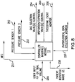
- FIG. 8 is a block diagram of a controller port configuration for a ventilator according to embodiments of the present invention.
- FIG. 9 is a schematic illustration of another alternative ventilator delivery system according to embodiments of the present invention.
- FIG. 10A is a schematic illustration of yet another ventilator delivery system according to embodiments of the present invention.
- FIG. 10B is a schematic illustration of an additional ventilator delivery system according to embodiments of the present invention.
- FIG. 11 is a timing diagram of inspiration and expiration that can be used in conjunction with embodiments of the present invention.
- FIG. 12 is a timing diagram of a ventilation cycle with breath-hold and associated trigger regions that can be used in conjunction with embodiments of the present invention.
- FIG. 13 is a timing diagram of inspiration stop in relation to the inspiration/expiration and breath-hold cycle according to embodiments of the present invention.
- FIG. 14 is a timing diagram of expiration stop in relation to inspiration/expiration and breath-hold cycle according to embodiments of the present invention.
- FIG. 15 is a block diagram of an automated dynamic pressure feedback system for controlling tidal volume or inspiration pressure for delivering hyperpolarized gas using a ventilator system according to embodiments of the present invention.
- FIG. 16 is a block diagram of operations that can be used to dispense a selected gas during ventilation of a subject according to embodiments of the present invention.
- FIG. 17 illustrates how FIGS. 17A-I are to be arranged so as to depict a schematic illustration of an automated ventilator system according to embodiments of the present invention.
- FIGS. 17A-I depict portions of the schematic illustration to be assembled according to FIG. 17 .
- forward and derivatives thereof refer to the general direction the target gas or target gas mixture travels as it moves through the ventilator system; this term is meant to be synonymous with the term “downstream,” which is often used in manufacturing environments to indicate that certain material being acted upon is farther along in the manufacturing process than other material.
- downstream which is often used in manufacturing environments to indicate that certain material being acted upon is farther along in the manufacturing process than other material.
- reverse and upstream refer to the directions opposite, respectively, the forward and downstream directions.
- polarized gases are produced and collected and may, in particular embodiments, be frozen, thawed, used alone and/or combined with other constituents, for MRI and/or NMR spectroscopy applications.
- polarized gas includes at least one polarized gas of interest (such as, but not limited to, 3 He and/or 129 Xe) and may include one or more other constituents such as other carrier, blending or buffer gases.
- polarize polarizer”, “polarized”, and the like are used interchangeably with the terms “hyperpolarize”, “hyperpolarizer”, “hyperpolarized” and the like.
- the ventilator systems and gas delivery valves contemplated by the present invention can be used for any target subjects and are hyperpolarized gas-compatible for NMR and/or MRI procedures. Although described herein for ease of discussion as a single gas delivery valve for delivering selectable ventilation gases, a plurality of discrete valves may also be used.
- Subjects can be any animal subject, and are preferably mammalian subjects (e.g., humans, canines, felines, bovines, caprines, ovines, equines, rodents, porcines, and/or lagomorphs).
- small animals includes mice, rats, guinea pigs, dogs, cats, monkeys, pigs, and rabbits.
- hyperpolarization can be induced by spin-exchange with an optically pumped alkali-metal vapor or alternatively by metastability exchange. See Albert et al., U.S. Pat. No. 5,545,396.
- the ventilated polarized gas may be a noble gas, such as 129 Xe or 3 He. Other gases and/or noble gases may also be used, alone or in combination. Buffer gas formulations may also be used as described in U.S. Pat. No. 6,295,834, the contents of which are hereby incorporated by reference as if recited in full herein.
- the polarized gas may comprise 13 C and/or 15 N compounds, such as organic molecules enriched in 13 C, which may be polarized using dynamic nuclear polarization (DNP) and/or para-hydrogen induced polarization.
- DNP dynamic nuclear polarization
- FIG. 1 illustrates operations that can be performed according to embodiments of the present invention.
- a ventilator system with a MFC (“mass flow controller”), tracheal tube and a gas delivery valve configured to (selectively) deliver hyperpolarized gas and a non-polarized gas is provided (block 100 ).
- a first pressure in the ventilator system upstream of the gas delivery valve is monitored (block 102 ).
- a second pressure in the ventilator system downstream of the gas delivery valve is monitored (block 104 ).
- the tidal volume of hyperpolarized gas delivered to the lungs can be automatically determined in situ using the flow rate of the MFC when the first pressure is in a substantially steady state condition (block 110 ).
- Steady state means that the pressure variation is within a desired tolerance such that it neither increases nor decreases over time during a desired interval.
- the ventilator system automatically controls and adjusts the MFC flow rate dynamically so as to maintain a substantially constant first pressure during delivery of the hyperpolarized gas.
- the system may automatically dynamically adjust the MFC flow rate to selectively provide a substantially constant P 1 pressure and/or a substantially constant flow rate from the MFC depending on whether the system is operating in a user-selectable set tidal volume mode or a PIP mode (block 109 ).
- the molar amount of hyperpolarized gas delivered in one or more tidal volumes can be calculated based on the determined tidal volume using the MFC data and adjusted to be at standard temperature and pressure (block 108 ). That is, the tidal volume can be measured at standard temperature and pressure and this value can be translated into moles at this volume at standard temperature and pressure to evaluate the number of moles of hyperpolarized gas delivered the subject's lungs is determined. The measured amount can be in the millimole range for small animal ventilation.
- FIGS. 2A-B illustrate operations that can be carried out to operate a ventilator and deliver hyperpolarized gas according to other embodiments of the present invention.
- the ventilator delivery system can include an MFC, a tracheal tube and first and second spaced apart pressure sensors (one located upstream of the gas delivery valve and/or tracheal tube and one located downstream of the gas delivery valve and/or on or in the tracheal tube).
- the sensors can be configured to automatically measure respective first and second pressures, P 1 , P 2 , in the ventilator system during operation.
- a desired breathing cycle, rate and/or inspiration rate can be set (i.e., breath per minute “BPM” and inspiration/expiration “I/E” ratio) (block 153 ).
- the tracheal tube can be positioned in the subject (before, during or after the operational mode is selected), in fluid communication with the lungs thereof (block 157 ).
- the MFC flow rate can be adjusted to provide a substantially constant P 1 (block 159 ).
- P 1 peak inspiration pressure
- the delivered amount of hyperpolarized gas can be output in situ using the calculated tidal volume (block 165 ).
- a predetermined portion of the ventilation system gas flow path including the tracheal tube defines a first static geometric volume “V1” (block 152 ).
- the first geometric volume “V1” can be subtracted from the calculated tidal volume V 1 ′ (block 154 ), which is the volume of gas exhausted during a (each) breath for a particular one or more PIP.
- the volumetric correction can provide a more representative or “truer” tidal volume delivered to small animals where small amounts can influence the results.
- the fixed geometry volume V 1 can be calculated using known or measured dimensions or dynamically determined when the first pressure stabilizes with the tracheal tube closed.
- a distal portion of the tracheal tube (the end that will be the deepest in the subject) can be capped or otherwise closed in situ, prior to insertion into the subject (block 155 ). That is, V 1 ′ can be determined using the value of the MFC when P 1 is in steady state operation. Because the downstream geometric volume is constant (with the tube closed), V 1 can be calculated from the change in pressure between PIP and atmospheric pressure. A selected gas can be delivered during the V 1 fixed geometry evaluation at a known flow rate, when the first pressure and the peak inspiration pressure (measured at P 2 ) stabilize or are in steady state during PIP, then flow in will equal the flow out (i.e., the flow during inspiration equals the flow during expiration) (block 156 ).
- the first and second pressures can be monitored and the data used to automatically and dynamically adjust selected operational parameters of the system so that the desired peak inspiration pressure is reached and the first pressure is stable (block 160 ).
- the dynamic adjustment(s) can be carried out to maintain a substantially constant first pressure during delivery of the polarized gas (block 162 ).
- the system can be operated on different selectable modes that can be set by the user; thus, the system can be operated via a set inspiration pressure mode, where the inspiration volume is determined, or measured, or a set tidal (inspiration) volume mode, where the inspiration pressure is measured (block 166 ).
- the “total” tidal volume V 1 ′ is measured (primarily representing the volume downstream of the gas delivery valve).
- the volumetric contribution of the tube V 1 may be subtracted at a particular PIP. For medium or large animals the volumetric correction for the tube may not be required.
- FIG. 3A illustrates one embodiment of a ventilator system 10 .
- the system 10 includes a controller 15 , a variable mass flow controller (MFC) 18 , a first pressure sensor 21 (shown as a pressure transducer PT 1 ), a gas delivery valve 25 , a second pressure sensor 27 , and a tracheal tube 30 .
- the gas delivery valve 25 is in fluid communication with a polarized gas source 43 and a non-polarized gas source 43 .
- the gas delivery valve 25 may optionally be in communication with additional gas sources (designated herein at feature 47 ).
- the mass flow controller 18 can be a variable calibrated mass flow controller, such as a voltage controlled controller p/n DFC2600 available from AALBORG located in Orangeburg, N.Y.
- FIG. 3A also illustrates the direction of flow in and flow out of the subject (shown by the arrows), shown as an animal subject 50 .
- the exhaust is directed out of the subject back through the tracheal tube 30 and out of the gas delivery valve 25 via vent port 25 v .
- the vent port 25 v may be in fluid communication with a gas sensor (not shown) that determines exhaled gas contents, concentration or ratios.
- a control feedback system is used to adjust the rate of flow of the mass flow controller 18 to control delivery of a desired volume to the subject.
- the feedback is based on monitored pressure readings of the first and second pressure sensors 21 , 27 .
- the first sensor 21 is disposed upstream of the gas delivery valve 25 proximate the mass flow controller 18 .
- the second sensor 27 is located downstream of the gas delivery valve 25 proximate the animal 50 .
- the sensor 27 can be a pressure transducer or other type of pressure sensor.
- the second pressure sensor 27 can be positioned in or on the endotracheal tube itself so as to be able to measure the pressure in the lungs by placing the sensor 27 as close to the source or target as possible.
- the senor 27 may be positioned upstream of the lungs.
- a port can be added to the gas delivery valve that connects to the tracheal tube through the valve body.
- flow in means flow into the volume of the gas flow path upstream of the gas delivery valve from the MFC and flow out means flow out of the volume downstream of the gas delivery valve. If the pressure at the first sensor 21 continues to increase during ventilation, then the flow rate is too great and the controller 15 can dynamically reduce the flow. If the pressure at the first sensor 21 decreases during ventilation, then additional flow is needed and the controller 15 can dynamically increase the flow. If the pressure at the first and/or second sensors 21 , 27 reaches a steady state condition during a peak inspiration pressure calculation, then the proper flow is being used.
- Readings of the mass flow controller 18 are based on a calibrated gas at standard pressure (1 ATM, 14.7 psia, 1033.51 cm H 2 O) and temperature (70 degrees F.). The temperature and pressure can be monitored and adjustments made (the readings normalized to the standard pressure and temperature) as suitable. For an initial or “first pass” operational set-up or evaluation, temperature effects can be assumed to be nominal. If the calibrated gas is not the gas used for output, a conversion constant can be applied to determine the flow set point. For example, if the mass flow controller 18 is calibrated for nitrogen but helium is used, then a conversion factor of 1.454 is used in the calculations. Table 1 lists examples of a conversion “K” factor for default settings (standard temperature and pressure) that can be used in calculating parameters used to operate the ventilator.
- FIG. 3B illustrates that a calibration pressure P 1 can be established when the tracheal tube 30 is capped (shown with an end cap 30 c ) and disposed outside of the body of the subject with the tracheal tube 30 closed (via cap, valve or other means) to close the exit end of the tracheal tube 30 while attached to the system 10 defining a first fixed system volume “V1” that can also be described as a calibration volume Vc (and sometimes described as Vcal hereinafter).
- the calibration volume Vc is associated with a predetermined portion of the ventilator system gas flow path having a fixed geometry as shown in FIG. 3A .
- the calibration volume Vc is that portion of the gas flow path has a length “L” that extends through a portion of the gas delivery valve 25 to the distal end 30 d of the tracheal tube 30 .
- the length may be about 12 inches.
- the endotracheal tube 30 may be formed of 1/16 inch inner diameter tubing that can releaseably connect to the valve 25 via a male luer lock (not shown).
- FIG. 3B illustrates one embodiment of a gas delivery valve 25 with a plurality of individually selectable gas valves 25 1 , 25 2 , 25 3 .
- the fixed volume V 1 in this embodiment is the volume indicated by the cross-hatched portion of the flow path, which includes the flow path extending downstream of or in advance of the valve 25 3 to the distal end 30 d of the tracheal tube 30 in the forward input flow direction and includes the connection to the pressure transducer 27 and, in the exhaust or output direction, from the tracheal tube to the valve 25 4 associated with vent port 25 v.
- FIG. 4 graphically illustrates the addition of this volume to the ventilator system 10 . That is, absent the pressure feedback control system, the system 10 with the tracheal tube 30 open and in the lungs delivers to a larger reservoir volume at the same flow rate thereby causing the pressure to decrease (shown by the fall in pressure noted in FIG. 4 when V 2 is added). However, the flow rate can be increased to again bring (or keep) the system 10 at a desired substantially constant pressure, as shown in FIG. 4 as the pressure returns to the P 1 value and levels off with the lungs added to the system (when the tracheal tube is open and in position in the subject).
- FIGS. 5A and 5B illustrate the pressure P 1 at the first sensor 21 in relation to the pressure at the second sensor 27 over time (t) during operation with the tracheal tube 30 in position in the subject.
- the pressure P 2 at the second sensor 27 is made in the subject's airway during operation and corresponds to the BPM and I/E ratio selected.
- the maximum P 2 pressure is the peak inspiration pressure (PIP).
- FIG. 5A illustrates pressure fluctuation in the first pressure that may cause measurement errors.
- FIG. 5B illustrates the system 10 being controlled to provide a substantially constant operating or system pressure P 1 , with P 1 being steady state or stable (not increasing or decreasing over time) and substantially equal to and/or greater than the PIP according to embodiments of the present invention.
- this P 1 pressure stability can be carried out using a capacitance volume located upstream of the gas delivery valve as will be discussed further below.
- the size of the capacitance can be tuned to reduce the fluctuations of P 1 shown in FIG. 5A so that P 1 behaves more like that shown in FIG. 5B . It is noted that oversizing the capacitance may slow the responsiveness of the system.
- the first sensor 21 can be a pressure transducer PT 1 that is used to monitor the pressure in the system 10 between the mass flow controller 18 and the gas delivery valve 25 based on the flow into the gas delivery valve 25 .
- the second sensor 27 can also be a pressure transducer, PT 2 , and can be used to monitor the airway pressure from the subject (which can be an animal).
- the gas delivery valve 25 can be configured for either supplying the air to the subject and/or for allowing the subject to hold breath or exhale.
- FIG. 6 illustrates an alternative embodiment of a ventilator system 10 ′ using a flow meter 31 in-line with either a source of supply gas(es) (not shown) and/or a vent port 25 v .
- Other embodiments can use an independent flow meter and a proportional valve (not shown).
- Still other embodiments can employ manually adjustable flow valves (also not shown). Combinations of the above may also be used.
- the lung volume can vary with PIP and BPM as lungs are typically somewhat elastic.
- an a priori evaluation of the animal expected lung physiological characteristics can be programmed to help establish flow rate adjustment increments and default operating parameters.
- the ventilator system 10 , 10 ′ can be operatively associated with a reference library of animal characteristics, such as, but not limited to, estimated lung volume versus pressure, PIP, BPM, flow rates, and the like to help operate the feedback control system.
- a reference library of animal characteristics such as, but not limited to, estimated lung volume versus pressure, PIP, BPM, flow rates, and the like to help operate the feedback control system.
- An example of default parameters is listed in Table 2 below.
- Certain embodiments of the gas delivery valve 25 employ at least one spool or piston to actuate at least one gas flow path in a NMR/MRI compatible valve body.
- This configuration may be particularly suitable for small animal ventilators used during NMR spectroscopy and/or MRI imaging sessions.
- a spool or shuttle valve see U.S. Provisional Patent Application Serial No. 60/450,209 filed Feb. 26, 2003, the contents of which are hereby incorporated by reference as if recited in full herein.
- Other valve configurations such as but not limited to, diaphragm and/or pincher valves may also be used.
- the gas delivery valve 25 can be configured to provide fast response times, which may be particularly suitable for use in situations where the subject is ventilated at a high BPM breathing rate with a low inhale/exhale or inspiration/expiration ratio (I/E).
- I/E ratio is the inspiration time over the expiration time.
- “Inspiration” is the time during which the gas is provided to the animal (or other subject) while “expiration” is the time during which the animal (or other subject) is exhaling. Therefore, a high BPM, such as about 180 BPM, means that each breath lasts 333 ms.
- An I/E of 20/80 means that the device has 67 ms to deliver the desired tidal volume to the animal (or other subject).
- the speed at which the valve opens can be important, as the faster the BPM, the smaller the I/E %, and the less time the valve has to open and supply the desired amount of gas to the animal (or other subject).
- the I/E ratio is typically within about 30/70 to 60/40, but can vary outside of this range, depending on the desired result.
- the I/E ratio and BPM can be substantially fixed during “normal” (non-imaging) breathing.
- the BPM and I/E ratio can be adjusted to be different for imaging (hyperpolarized gas) breath runs, but once the image run is over, these operating parameters can return to “normal” breathing parameters. See FIGS. 11-14 for examples of breath cycles according to embodiments of the present invention.
- 180 BPM may be an upper range for many small animal species and, in certain embodiments, the ventilators 10 , 10 ′ may operate at a lower rate.
- the operating parameters are animal species/weight driven. For example, mice use a faster BPM than a rabbit.
- the I/E ratio can change between animals but will typically stay within the range mentioned above.
- the BPM may be about 30 BPM for a small animal such as a mouse.
- valve may be configured for an “on-off” operation of a single gas or different gases to deliver or hold back a single gas (typically hyperpolarized gas) or different gases and/or to open and close the single or plurality of gas flow paths (not shown) for controlled inhalation delivery to a subject;
- gas delivery valve 25 can also be configured to select between inhale, exhale, and/or breath-hold ventilation operations.
- the valve body and polarized gas flow path can be formed from and/or coated with a material or materials selected for the ability to inhibit depolarization of hyperpolarized gas (such as due to relaxation attributed to gas interaction therewith). Coatings such as sol-gel coatings, deuterated polymer coatings, metal film coatings and other coatings and non-magnetic materials that inhibit depolarization can also be used. See, e.g., U.S. patent application Ser. No. 09/485,476 and U.S. Pat. Nos. 5,612,103 and 6,423,387, the contents of which are hereby incorporated by reference as if recited in full herein.
- valve body and/or components may be formed of materials such as, but not limited to, aluminum, TEDLAR, TEFLON, PTFE, DELRIN (acetal), and the like. Care should be taken to reduce the sources of friction by providing a smooth surface finish, and reducing the number of O-rings or selecting the O-ring material to reduce friction.
- the valve body can be fabricated to tolerances to provide sufficient seals and yet provide reduced friction between the spool and valve body receptacle.
- the valve body bore finishes, the interface with the endotracheal tube, any O-ring compression, and lubricants may all be considered to reduce the sources of friction.
- the endotracheal tube can also be configured from medical grade biocompatible materials, which are also configured with material(s) or coatings that inhibit hyperpolarized gas decay.
- the valve 25 can be configured to automatically provide a selection of ventilation breath outputs and/or inputs according to embodiments of the present invention as directed by the controller 15 .
- Gas A will be described as a hyperpolarized gas and Gas B as a non-polarized gas.
- a reverse configuration can be used.
- breath-hold means that the gas or gases are held in the lungs for a breath-hold time to facilitate bio-uptake of the gas and/or allow a stronger hyperpolarized gas signal relative to normal respiration.
- the breath-hold duration may be between 5-30 seconds.
- the valve 25 can be actuated to accommodate: (a) Gas “A” inhale; (b) Gas “B” inhale; (c) Gas “A”+Gas “B” inhale; (d) exhale; (e) partial exhale and breath hold; (f) Gas “A” inhale and breath hold; (g) Gas “B” inhale and hold; and (h) Gas “A”+Gas “B” inhale and breath hold.
- the hyperpolarized gas may be a hyperpolarized noble gas such as 3 He and/or 129 Xe.
- the non-polarized gas may be a mixture of non-polarized gases.
- the non-polarized gas can be selected to inhibit depolarization of the hyperpolarized gas, and may be also selected for biocompatibility.
- suitable non-polarized gases include, but are not limited to, nitrogen, xenon, and helium.
- the valve 25 may also be used to connect to an anesthetic vaporizer.
- valve 25 and polarized gas flow path in the ventilator system can be configured to reduce any dead volume for the inhaled gas(es).
- dead volume means the volume from source to subject such as within the valve or downstream system that needs to be filled with gas before the gas will reach the subject. The smaller the volume, the less gas that is “wasted”. Reducing the dead volume is particularly desirable when dispensing hyperpolarized gas because the hyperpolarized gas fills the volume of the flow path from source to subject and any polarized gas remaining in the dead volume may become unpolarized or decay to an undesirable polarization level, and must be displaced before suitably polarized gas can reach the subject on the next polarized breath.
- the ventilator system 10 , 10 ′ is configured to operate in an NMR/I suite having magnetic field strength up to about 5 T. In other embodiments, the ventilator 10 , 10 ′ can be configured to operate in a low magnetic field environment, typically under about 100 Gauss. The ventilator system 10 , 10 ′ can be configured to operate in intermediate field strengths as well, such as, but not limited to, greater than about 100 Gauss and up to about 1.5 T.
- the ventilator system 10 , 10 ′ can be configured to provide a tidal volume control of from about 0.2 mL to about 100 mL, in 0.1 mL increments.
- the system 10 , 10 ′ may be configured to operate with a BPM range of from about 5-180, with about a 1 BPM adjustable increment.
- the system 10 , 10 ′ may also be configured to allow selectable inspiration/expiration ratios from between about 5:1 to 1:5 with about a 1% increment adjustability and supply controlled PIP of from about 0-40 inches H 2 O with about 1 inch H 2 O increments.
- the tidal volume flow can range from about 0-5 liters/min.
- the ventilator 10 , 10 ′ can be shielded so that EMI/RFI produced shall not unduly affect the polarization level of the gas or the operation of the MRI/NMR equipment.
- FIG. 7 illustrates one configuration of a controller 15 according to certain embodiments of the present invention.
- the controller 15 can include at least one RS232 communication port 210 , a body temperature monitoring port 212 , a plurality of analog to digital and/or digital to analog ports 214 , and a trigger input/output port 216 that can sequence or generate gated trigger signals to an NMR/MRI system during or prior to signal acquisition.
- the gated trigger signal can relate to a desired portion of a breath-hold cycle and/or an “R” trigger in a detected QRS cardiac rhythm.
- the controller 15 can also include a physiological monitor connection port 218 that accepts data regarding at least one of heart rate, ECG, blood pressure, oxygen saturation levels, CO 2 during expiration, body temperature, and the like, as well as a pressure transducer input port(s) 219 .
- the temperature monitor can monitor internal animal body temperature and direct heating and/or cooling of the animal to maintain the temperature within a desired range.
- the temperature monitor may be independent of the controller 15 .
- FIG. 8 illustrates one embodiment of a controller 15 with an interface module having a plurality of different interface connections to remote, peripheral and/or integrated devices.
- the connections or ports include a control line to the mass flow controller 251 , a communication line between the first and second sensors 252 , 253 and a control line to the gas delivery valve 254 .
- the controller 15 can also have a gas delivery valve control line 255 configured to control and direct the flow direction, i.e., inspiration/expiration, a triggering event monitoring line 256 , and a physiological data collection communication line 257 .
- the controller 15 can also include a communication port to accept user input for operational parameters 259 and can include a communication port or line 258 that engages an NMR/MRI device or system lines to record tidal volume/PIP or other information on NMR/MRI signal acquisitions or images.
- FIG. 9 illustrates another embodiment of a ventilator system 10 ′′ according to the present invention.
- This embodiment may be particularly suitable to dispense polarized gas or gas mixtures proximate in time (i.e., just prior or during) to MRI/NMR imaging or signal acquisition in a specified tidal volume operational mode.
- the polarized gas source 43 comprises a compressible container 180 b inside a pressure vessel 180 .
- a constant flow of nitrogen is fed into a variable flow pressure regulator that controls the flow of the nitrogen into the vessel 180 .
- the nitrogen in the vessel 180 compresses the container 180 b that expels the hyperpolarized gas (Hp) to the gas delivery valve 25 .
- Hp hyperpolarized gas
- a pressure sensor 26 is located in the container and measures the pressure Pc used to compress the container 180 b .
- the tidal volume V T can be the same value as that calculated in a normal breath cycle.
- the system 10 ′′ applies pressure to the bag 180 b by pressurizing the chamber 180 c in the vessel 180 .
- the chamber 180 c can be pressurized to a pressure that is greater than the “current” PIP pressure (taken as a substantially real-time dynamic measurement).
- the pressure for the chamber 180 c can be determined by multiplying the PIP times a constant adjustment factor to adjust for the difference in density and distance to the animal.
- FIG. 16 is a block diagram of operations that can be carried out to ventilate a subject according to embodiments of the present invention.
- a ventilation system can be configured with a gas delivery valve and a tunable fluidic capacitance (block 400 ).
- the system can be configured with an adjustable capacitance volume that is at least about three times, typically at least about ten times, and more typically at least about 100 times greater than the size of the lungs of the target subject undergoing evaluation (block 401 ).
- the capacitance size may be selected based on the average size of the lungs of the animal species undergoing evaluation.
- the system can be tuned by adjusting the volume of fluid held in the system manifold line upstream of the gas delivery valve (block 405 ).
- the tuning can be carried out to maintain a substantially constant pressure (block 406 ).
- the increase and/or decrease in fluid can be carried out by selectively engaging-or disengaging one or more fixed volume lines or reservoirs (block 407 ) and/or by using a syringe that can inject and extract fluid from the system to adjust the capacitance.
- FIG. 10A illustrates one embodiment of a ventilator system 10 a with a variable mass flow tuning system having a tunable capacitance “C” that can reduce pressure variations and even out the operational pressure of the system 10 a .
- the system 10 a is configured with an increased fluid volume 301 and a syringe 300 or other input/output fluid adjustment mechanism that can add and/or remove a desired controlled amount of fluid to tune the system and create a substantially constant pressure at the first sensor 21 (as shown in FIG. 5B ).
- the capacitance volume may be between about 50-1500 ml.
- the system 10 a can also include a pressure regulator 16 disposed upstream of the mass flow controller 18 .
- the capacitance is defined by a fluid volume 301 upstream of the gas delivery valve 25 .
- the capacitance can be at least ten times the volume of the lungs, and typically at least about 100 times greater than the volume of the lungs of the subject.
- the system 10 a can be configured with a 300 ml fluid capacitance.
- FIG. 10B illustrates another embodiment of a system 10 b .
- a three-way valve 114 can be positioned intermediate the mass flow controller 18 and polarized gas source 43 .
- the system 10 b can also include a pressure regulator 14 in communication with the three-way valve 114 and a pressure regulator 16 upstream of the mass flow controller 18 .
- the three-way valve 114 is configured to temporarily disconnect the mass flow controller 18 when the system 10 b is in the tidal volume dispensing mode (operating to dispense a selected predetermined tidal volume of hyperpolarized gas).
- the nitrogen pressure can be controlled or set by the pressure regulator 14 and reservoir or lump capacitance 301 (defined by one or more upstream reservoirs or fixed volumes (tied into the line in series or parallel) to keep the pressure substantially steady state during tidal volume dispensing of the polarized gas.
- the nitrogen at a controlled pressure is then directed into vessel 180 to compress the bag 180 b of hyperpolarized gas. Examples of suitable bags are described in U.S. Pat. No. 6,423,387, the content of which is hereby incorporated by reference as if recited in full herein.
- FIG. 11 illustrates the basic components of a breath cycle during ventilation. As shown, there is an inspiration and expiration duration that can be selected based on the I/E ratio. In the embodiment shown in FIG. 11 , there is also a region for input trigger delay 300 t I (the trigger for obtaining an MRI/NMR signal) can be timed to start a predetermined delay period from this time in the cycle.
- FIG. 12 illustrates the breath cycle with a hold-breath portion and three potential regions for output trigger delays: an output trigger delay from the start of inspiration 300 t OI ; an output trigger delay from the start of breath hold time 300 t OH ; and an output trigger delay from the start of expiration 300 t OE .
- FIGS. 13 and 14 illustrate different portions of the breath cycle in which to initiate the breath-hold time of the polarized gas.
- FIG. 13 illustrates an inspiration stop and
- FIG. 14 illustrates an expiration stop.
- FIG. 17 and FIGS. 17A-I illustrate an example of an automated ventilator system 10 d according to certain embodiments of the present invention.
- the system 10 d includes a gas control module 500 that may be configured to reside in a desktop enclosure.
- the gas control module 500 includes a breathing gas control system 510 , a polarized gas control system 520 , and a gas delivery valve 25 control system 530 .
- the breathing gas control system 510 includes a first breathing gas input 500 i with associated pressures sensors, valves, and regulators, as well as the mass flow controller 18 and first pressure sensor 21 .
- the breathing gas control section 510 can also be in communication with an adjustable capacitance volume reservoir 301 (which can have a capacitance volume of between about 50-1500 ml, or even more, in certain embodiments).
- the breathing gas control system 510 can also be in communication with an anesthetic vaporizer and/or scrubber. Small inner diameter conduit (typically about 1 ⁇ 8- 1/16 of an inch) can be used to connect components.
- the breathing gas control system 510 can include an optional second breathing gas input 500 i 2 .
- the polarized gas control system 520 also includes pressure regulators, pressure sensors, and valves that are in communication with the polarized gas source 43 .
- the polarized gas source 43 is, in turn, in communication with the gas delivery valve 25 via small inner diameter polarization friendly tubing (shown as 1/16 inch i.d. tubing).
- the gas delivery valve 25 control system 530 includes a pressure regulator and pressure transducer and a series of valves that control inhale, exhale and gas output to the subject.
- the configuration shown contemplates the use of a diaphragm valve 25 , but as noted above, other gas delivery valve 25 configurations can be used and the gas delivery valve control system 530 modified accordingly.
- orifices can be added to the transducer lines (not shown).
- the control module 500 can be configured to be in communication with various components and peripheral devices.
- the system 10 d can include a vital signs/power supply module 550 that may also be provided in the desktop enclosure housing the control module 500 .
- the vital signs/power supply module 550 can include a blood pressure sub-module 552 that communicate with a blood pressure sensor 550 s , a cardiotachometer sub-module 553 that communicates with a heart monitoring sensor 550 s , and a gas pressure sub-module 551 .
- the system 10 d can also include a blanket-type heating pad 560 with temperature controller 570 .
- the system 10 d can also include an optional CO 2 analyzer 575 1 and/or scrubber 575 2 connected to vent port 25 v of the valve 25 .
- the system 10 d can be software controlled for automated operation.
- the system can employ two mass flow controllers 18 and 18 2 .
- the mass flow controllers can be used to blend standard ventilation gases (such as oxygen and air) during non-polarized gas ventilation.
- the system can be configured to automatically control the operation of the supplemental mass flow controller to deliver a desired blend, mix or concentration of gases to the subject (such as to supply about 30% oxygen with 70% air).
- the present invention may be embodied as a method, data or signal processing system, or computer program product. Accordingly, the present invention may take the form of an entirely hardware embodiment, an entirely software embodiment or an embodiment combining software and hardware aspects. Furthermore, the present invention may take the form of a computer program product on a computer-usable storage medium having computer-usable program code means embodied in the medium. Any suitable computer readable medium may be utilized including hard disks, CD-ROMs, optical storage devices, or magnetic storage devices.
- the computer-usable or computer-readable medium may be, for example but not limited to, an electronic, magnetic, optical, electromagnetic, infrared, or semiconductor system, apparatus, device, or propagation medium. More specific examples (a nonexhaustive list) of the computer-readable medium would include the following: an electrical connection having one or more wires, a portable computer diskette, a random access memory (RAM), a read-only memory (ROM), an erasable programmable read-only memory (EPROM or Flash memory), an optical fiber, and a portable compact disc read-only memory (CD-ROM).
- RAM random access memory
- ROM read-only memory
- EPROM or Flash memory erasable programmable read-only memory
- CD-ROM portable compact disc read-only memory
- the computer-usable or computer-readable medium could even be paper or another suitable medium upon which the program is printed, as the program can be electronically captured, via, for instance, optical scanning of the paper or other medium, then compiled, interpreted or otherwise processed in a suitable manner if necessary, and then stored in a computer memory.
- Computer program code for carrying out operations of the present invention may be written in an object oriented programming language such as Java7, Smalltalk, Python, or C++. However, the computer program code for carrying out operations of the present invention may also be written in conventional procedural programming languages, such as the “C” programming language or even assembly language.
- LAN local area network
- WAN wide area network
- Internet Service Provider for example, AT&T, MCI, Sprint, EarthLink, MSN, GTE, etc.
- FIG. 15 is a block diagram of exemplary embodiments of data processing systems that illustrates systems, methods, and computer program products in accordance with embodiments of the present invention.
- the processor 310 communicates with the memory 314 via an address/data bus 348 .
- the processor 310 can be any commercially available or custom microprocessor.
- the memory 314 is representative of the overall hierarchy of memory devices containing the software and data used to implement the functionality of the data processing system 305 .
- the memory 314 can include, but is not limited to, the following types of devices: cache, ROM, PROM, EPROM, EEPROM, flash memory, SRAM, and DRAM.
- the memory 314 may include several categories of software and data used in the data processing system 305 : the operating system 352 ; the application programs 354 ; the input/output (I/O) device drivers 358 ; an automated dynamic pressure feedback flow adjustment module with selectable inspiration tidal volume and PIP operational modes 350 ; and the data 356 .
- the data 356 may include ventilation system operational data 362 which may be obtained from the ventilation system, patient physiological data, and/or may be NMR/MRI data from an NMR spectroscopy or MRI system 320 .
- the operating system 352 may be any operating system suitable for use with a data processing system, such as OS/2, AIX or OS/390 from International Business Machines Corporation, Armonk, N.Y., WindowsXP, WindowsCE, WindowsNT, Windows95, Windows98 or Windows2000 from Microsoft Corporation, Redmond, Wash., PalmOS from Palm, Inc., MacOS from Apple Computer, UNIX, FreeBSD, or Linux, proprietary operating systems or dedicated operating systems, for example, for embedded data processing systems.
- the I/O device drivers 358 typically include software routines accessed through the operating system 352 by the application programs 354 to communicate with devices such as I/O data port(s), data storage 356 and certain memory 314 components and/or the image acquisition system 320 .
- the application programs 354 are illustrative of the programs that implement the various features of the data processing system 305 and preferably include at least one application that supports operations according to embodiments of the present invention.
- the data 356 represents the static and dynamic data used by the application programs 354 , the operating system 352 , the I/O device drivers 358 , and other software programs that may reside in the memory 314 .
- the present invention is illustrated, for example, with reference to the Feedback Module 350 being an application program in FIG. 15 , as will be appreciated by those of skill in the art, other configurations may also be utilized while still benefiting from the teachings of the present invention.
- the Pressure Feedback Module 350 may also be incorporated into the operating system 352 , the I/O device drivers 358 or other such logical division of the data processing system 305 .
- the present invention should not be construed as limited to the configuration of FIG. 15 , which is intended to encompass any configuration capable of carrying out the operations described herein.
- the Pressure Feedback Module 350 includes computer program code for timing the delivery of the desired inhalation gas(es) and may include code for tracking polarization level data of the dispensed hyperpolarized gas.
- the Module 350 can direct initiation of operations that will automatically sequence the system to output at a desired breath per minute rate, a desired I/E ratio, a target breath-hold time and may automatically adjust the pressure in the system based on sensed pressures.
- the I/O data port can be used to trigger NMR/MRI signal acquisition and/or to transfer information between the data processing system 305 and the NMR/MRI data acquisition system 320 or another computer system, a network (e.g., the Internet) or other device controlled by the processor.
- These components may be conventional components such as those used in many conventional data processing systems, which may be configured in accordance with the present invention to operate as described herein.
- each block in the flow charts or block diagrams represents a module, segment, or portion of code, which comprises one or more executable instructions for implementing the specified logical function(s).
- Certain of the flowcharts and block diagrams illustrate methods to operate hyperpolarizers or components thereof to yield polarized gas according to embodiments of the present invention.
- each block in the flow charts or block diagrams represents a module, segment, or portion of code, which comprises one or more executable instructions for implementing the specified logical function(s).
- the functions noted in the blocks may occur out of the order noted in the figures. For example, two blocks shown in succession may in fact be executed substantially concurrently or the blocks may sometimes be executed in the reverse order, depending upon the functionality involved.
- the systems 10 , 10 ′, 10 ′′, 10 a , 10 b can be configured to operate on the theory of flow into the system is equal to the flow out of the system.
- the following non-limiting example is provided in further description of the present invention.
- the following exemplary listing of sequence of operations can be used to deliver gas from the ventilator.
- the ventilation systems of the present invention allow for computer control and adjustment of the tidal volume and peak inspiration pressure delivered to the animal.
- the systems can also be configured to allow for data feedback from both sides of the gas delivery valve(s) and utilizes this feedback to make automated adjustments during operation of the device.
- the systems can include a mass flow controller so that the mole concentration to the animal can be determined.
Abstract
Ventilator systems include: (a) a mass flow controller; (b) a gas delivery valve in communication with the mass flow controller and configured to selectively dispense a plurality of different gases to a subject; (c) a first gas source in fluid communication with the gas delivery valve; (d) a second gas source in fluid communication with the gas delivery valve; (e) a first pressure sensor located upstream of the gas delivery valve; (f) a second pressure sensor located downstream of the gas delivery valve; and (g) a controller operatively associated with the first and second pressure sensors and the mass flow controller, the controller comprising computer program code that monitors the pressures measured by the first and second pressure sensors and automatically dynamically adjusts the flow rate of the mass flow controller.
Description
The present invention relates to the delivery of polarized noble gases to subjects for evaluations using NMR spectroscopy and/or magnetic resonance imaging (“MRI”).
Polarized inert noble gases can produce improved NMR signals in and/or MRI images of certain areas and regions of the body. Noble gases, such as polarized helium-3 (“3He”) and xenon-129 (“129Xe”), have been found to be particularly suited for this purpose. Unfortunately, the polarized state of the gases is sensitive to handling and environmental conditions and can, undesirably, decay from the polarized state relatively quickly.
Hyperpolarizers are used to produce and accumulate polarized noble gases. Hyperpolarizers artificially enhance the polarization of certain noble gas nuclei (such as 129Xe or 3He) over the natural or equilibrium levels, i.e., the Boltzmann polarization. Such an increase is desirable because it enhances and increases the MRI signal intensity, allowing physicians to obtain better images of the substance in the body. See U.S. Pat. Nos. 5,545,396; 5,642,625; 5,809,801; 6,079,213, and 6,295,834; the disclosures of these patents are hereby incorporated by reference herein as if recited in full herein.
In order to produce the hyperpolarized gas, the noble gas can be blended with optically pumped alkali metal vapors such as rubidium (“Rb”). These optically pumped metal vapors collide with the nuclei of the noble gas and hyperpolarize the noble gas through a phenomenon known as “spin-exchange.” The “optical pumping” of the alkali metal vapor is produced by irradiating the alkali-metal vapor with circularly polarized light at the wavelength of the first principal resonance for the alkali metal (e.g., 795 nm for Rb). Generally stated, the ground state atoms become excited, then subsequently decay back to the ground state. Under a modest magnetic field (10 Gauss), the cycling of atoms between the ground and excited states can yield nearly 100% polarization of the atoms in a few microseconds. This polarization is generally carried by the lone valence electron characteristics of the alkali metal. In the presence of non-zero nuclear spin noble gases, the alkali-metal vapor atoms can collide with the noble gas atoms in a manner in which the polarization of the valence electrons is transferred to the noble-gas nuclei through a mutual spin flip “spin-exchange.” Alternative polarization enhancement techniques may also be used.
After the polarization process, the hyperpolarized gas is typically separated from the alkali metal (where spin-exchange techniques have been employed) prior to administration to a patient to form a non-toxic pharmaceutically acceptable product. Unfortunately, during production and/or during and after collection, the hyperpolarized gas can deteriorate or decay relatively quickly (lose its hyperpolarized state) and therefore must be handled, collected, transported, and stored carefully.
In the past, several researchers have used hyperpolarized gas compatible ventilators for delivering polarized gas to subjects to image hyperpolarized noble gases such as helium and xenon. For example, Hedlund et al., in MR-compatible ventilator for small animals; computer controlled ventilation for proton and noble gas imaging, 18 Magnetic Resonance Imaging, pp. 753-759 (2000), state that ventilators have been in routine use in their laboratory for a number of years. See also, Hedlund et al., Three-dimensional MR microscopy of pulmonary dynamics, Society of Magnetic Resonance (New York, N.Y., 1996); and a poster presented by Hedlund et al. at the Amer. Thoracic Society 1998 International Meeting (Chicago, 1998), entitled MRI of pulmonary airways with hyperpolarized helium; a computer-controlled ventilator for imaging synchronous gas delivery in animal studies (describing ventilator technology). In addition, Black and co-workers have used a hyperpolarized gas-compatible ventilator to generate what is believed to be the first ever in vivo images of hyperpolarized 3He in guinea pig lungs. See Black et al., In vivo He-3 MR images of guinea pig lungs, Radiology, 199(3), pp. 867-870 (1996). One known commercial small animal ventilator that may have been modified to dispense hyperpolarized gas and other respiratory gases have been is believed to be available from CWE Inc. (Ardmore, Pa.) as Model SAR-830.
Unfortunately, conventional small animal ventilators used to deliver hyperpolarized gases do not provide a way to accurately determine the volume delivered to the animal. Generally stated, conventional ventilators cannot adequately determine the volume delivered to the animal lungs separate from the volume delivered by the system itself. For example, certain conventional ventilators have proposed using flow meters with pressure transducers that control inspiration pressure and calculate an estimated volume by averaging the flow output to the subject over time. The variability in such an estimate may be undesirable, particularly when the amount of delivered polarized gas is small and the MRI/NMR signal depends on the amount, concentration and polarization level of polarized gas delivered, such as is the case for polarized gas investigations of small animals using millimole concentration ranges.
Thus, there remains a need for systems that can more accurately determine the amount of a gas and/or number of moles of gas delivered to an animal's lungs.
Embodiments of the present invention can provide improved MRI compatible hyperpolarized gas delivery systems, methods, and computer program products that can calculate ventilation-dispensed polarized gas volumes based on (automated) measurements taken in situ at the animal delivery site to provide one or more of: (a) a known or calculated inspiration or tidal volume of gas; (b) automated controlled volumetric delivery; (c) in situ real-time or dynamic adjustment of flow rate based on pressure and volume parameters; and (d) controlled ventilation to provide blends or selectable respiratory gases, including at least one hyperpolarized gas.
Certain embodiments of the present invention include a feedback pressure or flow rate control system that can automatically monitor inlet and outlet pressures to adjust the flows to maintain a steady state condition during measurement/calculation (i.e., flow in=flow out). Thus, embodiments of the present invention can maintain the system at a substantially constant pressure upstream of the gas delivery valve based on an automated in situ assessment of parameters associated with the system.
Particular embodiments of the present invention are configured with a tunable capacitance system to provide steady state pressure for controlled delivery of polarized gas or gas blends. The capacitance may be provided by a fluid-filled syringe that acts as a tuning capacitor with fluid that is added or subtracted from the system flow path.
The inspiration pressure can be set and a known volume delivered and/or the inspiration volume can be set and a known pressure delivered.
Certain embodiments of the present invention are directed to ventilator systems having a ventilation flow path for ventilating a subject. The systems include: (a) a mass flow controller; (b) a gas delivery valve in communication with the mass flow controller and configured to selectively dispense a plurality of different gases to a subject; (c) a first gas source in fluid communication with the gas delivery valve; (d) a second gas source in fluid communication with the gas delivery valve; (e) a first pressure sensor located upstream of the gas delivery valve; (f) a second pressure sensor located downstream of the gas delivery valve; and (g) a controller operatively associated with the first and second pressure sensors and the mass flow controller a controller operatively associated with the first and second pressure sensors and the mass flow controller, the controller configured to monitor the pressures measured by the first and second pressure sensors and the flow rate of the mass flow controller and automatically determine a delivered tidal volume using a reading of the flow rate of the mass flow controller when the first pressure is at a substantially steady state condition.
The system can also include a tracheal tube and the controller can be configured to adjust the flow rate to generate a substantially constant pressure at the first pressure sensor during delivery of the polarized gas.
Other embodiments are directed to methods of delivering hyperpolarized gas to a subject. The methods include: (a) providing a ventilator system with a mass flow controller, a tracheal tube and a gas delivery valve configured to deliver hyperpolarized gas and at least one non-polarized gas to a subject; (b) monitoring a first pressure in the ventilator system upstream of the gas delivery valve; (c) monitoring a second pressure in the ventilator system downstream of the gas delivery valve; (d) obtaining a reading of the mass flow controller when the first pressure is substantially constant; and (e) automatically determining the tidal inspiration volume of hyperpolarized gas delivered to the subject in situ using the obtained mass flow controller reading.
Other embodiments are directed to a system for delivering hyperpolarized gas to a subject, including: (a) a gas delivery valve configured to deliver hyperpolarized gas and at least one non-polarized gas to a subject; (b) a mass flow controller disposed upstream of the gas delivery valve; (c) a tracheal tube disposed downstream of the gas delivery valve; (d) means for monitoring a first pressure in the ventilator system upstream of the gas delivery valve; (e) means for monitoring a second pressure in the ventilator system downstream of the gas delivery valve; (f) means for automatically obtaining readings of the mass flow controller; and (g) means for automatically determining the tidal inspiration volume of hyperpolarized gas delivered to the subject in situ using the monitored first pressure and the value of a reading of the mass flow controller obtained when the first pressure is substantially constant.
In certain embodiments, the ventilator system can include a variable mass flow controller disposed upstream of the gas handling valve and the method can be carried out to automatically dynamically adjust the flow rate of the mass flow controller to maintain a substantially constant first pressure during ventilation delivery of the hyperpolarized gas to the subject.
The system and/or method can also operate to accept user input to select a desired operational mode such as either a tidal volume operational mode with the desired tidal volume selected or a peak inspiration pressure operational mode with the desired peak inspiration pressure selected.
Still other embodiments are directed to ventilator systems having a ventilation flow path for ventilating a subject. The systems include: (a) a gas delivery valve configured to selectively dispense a plurality of different gases to a subject; (b) a mass flow controller disposed upstream of the gas delivery valve; (c) a first polarized source in fluid communication with the gas delivery valve; (d) a second gas source in fluid communication with the gas delivery valve; (e) a first pressure sensor located upstream of the gas delivery valve; (f) a second pressure sensor located downstream of the gas delivery valve; and (g) a manifold line having a fluidic tunable capacitance disposed upstream of the gas delivery valve. The fluidic capacitance has a volume that is at least about 10 times greater than the volume of the lungs of the subject.
The system can include at least one fixed volume reservoir (or line) that is configured to selectively engage the manifold to adjust the fluidic capacitance responsive to pressure measurements obtained by the first and second pressure sensors. The system may include a syringe with a quantity of fluid therein with the syringe being in communication with the manifold line and configured to selectively add or remove fluid from the manifold.
All, or selected operations, features, functions and/or configurations of the embodiments described above may be carried out as methods, systems, computer program products, assemblies and/or devices as contemplated by the present invention.
The foregoing and other objects and aspects of the present invention are explained in detail herein.
The present invention will now be described more fully hereinafter with reference to the accompanying figures, in which preferred embodiments of the invention are shown. This invention may, however, be embodied in many different forms and should not be construed as limited to the embodiments set forth herein. Like numbers refer to like elements throughout. In the drawings, layers, regions, or components may be exaggerated for clarity. In the figures, broken lines indicate optional features unless described otherwise.
In the description of the present invention that follows, certain terms may be employed to refer to the positional relationship of certain structures relative to other structures. As used herein the term “forward” and derivatives thereof refer to the general direction the target gas or target gas mixture travels as it moves through the ventilator system; this term is meant to be synonymous with the term “downstream,” which is often used in manufacturing environments to indicate that certain material being acted upon is farther along in the manufacturing process than other material. Conversely, the terms “rearward” and “upstream” and derivatives thereof refer to the directions opposite, respectively, the forward and downstream directions.
Also, as described herein, polarized gases are produced and collected and may, in particular embodiments, be frozen, thawed, used alone and/or combined with other constituents, for MRI and/or NMR spectroscopy applications. As also used herein, the term “polarized gas” includes at least one polarized gas of interest (such as, but not limited to, 3He and/or 129Xe) and may include one or more other constituents such as other carrier, blending or buffer gases. Further, the terms “polarize”, “polarizer”, “polarized”, and the like are used interchangeably with the terms “hyperpolarize”, “hyperpolarizer”, “hyperpolarized” and the like.
The ventilator systems and gas delivery valves contemplated by the present invention can be used for any target subjects and are hyperpolarized gas-compatible for NMR and/or MRI procedures. Although described herein for ease of discussion as a single gas delivery valve for delivering selectable ventilation gases, a plurality of discrete valves may also be used. “Subjects”, according to the present invention, can be any animal subject, and are preferably mammalian subjects (e.g., humans, canines, felines, bovines, caprines, ovines, equines, rodents, porcines, and/or lagomorphs). The term “small animals” includes mice, rats, guinea pigs, dogs, cats, monkeys, pigs, and rabbits.
Various techniques have been employed to accumulate and capture polarized gases. For example, U.S. Pat. No. 5,642,625 to Cates et al. describes a high volume hyperpolarizer for spin-exchange polarized noble gas and U.S. Pat. No. 5,809,801 to Cates et al. describes a cryogenic accumulator for spin-polarized 129Xe. As used herein, the terms “hyperpolarize,” “polarize,” and the like, are used interchangeably and mean to artificially enhance the polarization of certain noble gas nuclei over the natural or equilibrium levels. Such an increase is desirable because it allows stronger imaging signals corresponding to better NMR spectroscopy and/or MRI images of the substance and a targeted area of the body. As is known by those of skill in the art, hyperpolarization can be induced by spin-exchange with an optically pumped alkali-metal vapor or alternatively by metastability exchange. See Albert et al., U.S. Pat. No. 5,545,396.
In particular embodiments, the ventilated polarized gas may be a noble gas, such as 129Xe or 3He. Other gases and/or noble gases may also be used, alone or in combination. Buffer gas formulations may also be used as described in U.S. Pat. No. 6,295,834, the contents of which are hereby incorporated by reference as if recited in full herein. In other embodiments, the polarized gas may comprise 13C and/or 15N compounds, such as organic molecules enriched in 13C, which may be polarized using dynamic nuclear polarization (DNP) and/or para-hydrogen induced polarization.
The molar amount of hyperpolarized gas delivered in one or more tidal volumes (the tidal volume can be described as the change in volume during each breath) can be calculated based on the determined tidal volume using the MFC data and adjusted to be at standard temperature and pressure (block 108). That is, the tidal volume can be measured at standard temperature and pressure and this value can be translated into moles at this volume at standard temperature and pressure to evaluate the number of moles of hyperpolarized gas delivered the subject's lungs is determined. The measured amount can be in the millimole range for small animal ventilation.
A predetermined portion of the ventilation system gas flow path including the tracheal tube defines a first static geometric volume “V1” (block 152). In operation, the first geometric volume “V1” can be subtracted from the calculated tidal volume V1′ (block 154), which is the volume of gas exhausted during a (each) breath for a particular one or more PIP. The volumetric correction can provide a more representative or “truer” tidal volume delivered to small animals where small amounts can influence the results. The fixed geometry volume V1 can be calculated using known or measured dimensions or dynamically determined when the first pressure stabilizes with the tracheal tube closed.
In particular embodiments, a distal portion of the tracheal tube (the end that will be the deepest in the subject) can be capped or otherwise closed in situ, prior to insertion into the subject (block 155). That is, V1′ can be determined using the value of the MFC when P1 is in steady state operation. Because the downstream geometric volume is constant (with the tube closed), V1 can be calculated from the change in pressure between PIP and atmospheric pressure. A selected gas can be delivered during the V1 fixed geometry evaluation at a known flow rate, when the first pressure and the peak inspiration pressure (measured at P2) stabilize or are in steady state during PIP, then flow in will equal the flow out (i.e., the flow during inspiration equals the flow during expiration) (block 156).
The first and second pressures can be monitored and the data used to automatically and dynamically adjust selected operational parameters of the system so that the desired peak inspiration pressure is reached and the first pressure is stable (block 160). The dynamic adjustment(s) can be carried out to maintain a substantially constant first pressure during delivery of the polarized gas (block 162). The system can be operated on different selectable modes that can be set by the user; thus, the system can be operated via a set inspiration pressure mode, where the inspiration volume is determined, or measured, or a set tidal (inspiration) volume mode, where the inspiration pressure is measured (block 166).
In any event, when the tidal volume is measured, the “total” tidal volume V1′ is measured (primarily representing the volume downstream of the gas delivery valve). The volumetric contribution of the tube V1 may be subtracted at a particular PIP. For medium or large animals the volumetric correction for the tube may not be required.
Generally described, in operation, a control feedback system is used to adjust the rate of flow of the mass flow controller 18 to control delivery of a desired volume to the subject. The feedback is based on monitored pressure readings of the first and second pressure sensors 21, 27. The first sensor 21 is disposed upstream of the gas delivery valve 25 proximate the mass flow controller 18. The second sensor 27 is located downstream of the gas delivery valve 25 proximate the animal 50. The sensor 27 can be a pressure transducer or other type of pressure sensor. In certain embodiments, the second pressure sensor 27 can be positioned in or on the endotracheal tube itself so as to be able to measure the pressure in the lungs by placing the sensor 27 as close to the source or target as possible. However, in certain particular embodiments, such as when the tracheal tube diameter is very small such as for use with mice and the like, the sensor 27 may be positioned upstream of the lungs. A port can be added to the gas delivery valve that connects to the tracheal tube through the valve body.
The operational premise of “flow in=flow out” can be used in certain situations. Flow in means flow into the volume of the gas flow path upstream of the gas delivery valve from the MFC and flow out means flow out of the volume downstream of the gas delivery valve. If the pressure at the first sensor 21 continues to increase during ventilation, then the flow rate is too great and the controller 15 can dynamically reduce the flow. If the pressure at the first sensor 21 decreases during ventilation, then additional flow is needed and the controller 15 can dynamically increase the flow. If the pressure at the first and/or second sensors 21, 27 reaches a steady state condition during a peak inspiration pressure calculation, then the proper flow is being used.
Readings of the mass flow controller 18 are based on a calibrated gas at standard pressure (1 ATM, 14.7 psia, 1033.51 cm H2O) and temperature (70 degrees F.). The temperature and pressure can be monitored and adjustments made (the readings normalized to the standard pressure and temperature) as suitable. For an initial or “first pass” operational set-up or evaluation, temperature effects can be assumed to be nominal. If the calibrated gas is not the gas used for output, a conversion constant can be applied to determine the flow set point. For example, if the mass flow controller 18 is calibrated for nitrogen but helium is used, then a conversion factor of 1.454 is used in the calculations. Table 1 lists examples of a conversion “K” factor for default settings (standard temperature and pressure) that can be used in calculating parameters used to operate the ventilator.
| TABLE 1 |
| K Factors |
| GAS | K Factor based on N2 calibration gas | ||
| Air | 1.0000 | ||
| AR | 1.4573 | ||
| He | 1.4540 | ||
| N2 | 1.0000 | ||
| N2O | 0.7128 | ||
| O2 | 1.0000 | ||
After the tracheal tube 30 is placed in operative position, in fluid communication with the lungs of the subject, the lungs have an associated tidal volume that changes during a breath, this volume is added to the first system volume V1 to provide a total tidal volume V1′. FIG. 4 graphically illustrates the addition of this volume to the ventilator system 10. That is, absent the pressure feedback control system, the system 10 with the tracheal tube 30 open and in the lungs delivers to a larger reservoir volume at the same flow rate thereby causing the pressure to decrease (shown by the fall in pressure noted in FIG. 4 when V2 is added). However, the flow rate can be increased to again bring (or keep) the system 10 at a desired substantially constant pressure, as shown in FIG. 4 as the pressure returns to the P1 value and levels off with the lungs added to the system (when the tracheal tube is open and in position in the subject).
Referring back to FIG. 3A , in certain embodiments, the first sensor 21 can be a pressure transducer PT1 that is used to monitor the pressure in the system 10 between the mass flow controller 18 and the gas delivery valve 25 based on the flow into the gas delivery valve 25. The second sensor 27 can also be a pressure transducer, PT2, and can be used to monitor the airway pressure from the subject (which can be an animal). The gas delivery valve 25 can be configured for either supplying the air to the subject and/or for allowing the subject to hold breath or exhale.
The lung volume can vary with PIP and BPM as lungs are typically somewhat elastic. Thus, an a priori evaluation of the animal expected lung physiological characteristics can be programmed to help establish flow rate adjustment increments and default operating parameters. For example, the ventilator system 10, 10′ can be operatively associated with a reference library of animal characteristics, such as, but not limited to, estimated lung volume versus pressure, PIP, BPM, flow rates, and the like to help operate the feedback control system. An example of default parameters is listed in Table 2 below.
| TABLE 2 |
| Default Parameters |
| Animal | Tidal Volume | BPM | I/E | ||
| Mice | 0.3 |
110 | 30/70 | ||
| Rats | 1.5 mL | 60 | 30/70 | ||
| Guinea Pigs | 4.0 |
50 | 30/70 | ||
| Rabbits | 18.0 |
35 | 30/70 | ||
Certain embodiments of the gas delivery valve 25 employ at least one spool or piston to actuate at least one gas flow path in a NMR/MRI compatible valve body. This configuration may be particularly suitable for small animal ventilators used during NMR spectroscopy and/or MRI imaging sessions. For additional description of a spool or shuttle valve, see U.S. Provisional Patent Application Serial No. 60/450,209 filed Feb. 26, 2003, the contents of which are hereby incorporated by reference as if recited in full herein. Other valve configurations, such as but not limited to, diaphragm and/or pincher valves may also be used.
In any event, the gas delivery valve 25 can be configured to provide fast response times, which may be particularly suitable for use in situations where the subject is ventilated at a high BPM breathing rate with a low inhale/exhale or inspiration/expiration ratio (I/E). The I/E ratio is the inspiration time over the expiration time. “Inspiration” is the time during which the gas is provided to the animal (or other subject) while “expiration” is the time during which the animal (or other subject) is exhaling. Therefore, a high BPM, such as about 180 BPM, means that each breath lasts 333 ms. An I/E of 20/80 means that the device has 67 ms to deliver the desired tidal volume to the animal (or other subject). The speed at which the valve opens can be important, as the faster the BPM, the smaller the I/E %, and the less time the valve has to open and supply the desired amount of gas to the animal (or other subject).
The I/E ratio is typically within about 30/70 to 60/40, but can vary outside of this range, depending on the desired result. The I/E ratio and BPM can be substantially fixed during “normal” (non-imaging) breathing. The BPM and I/E ratio can be adjusted to be different for imaging (hyperpolarized gas) breath runs, but once the image run is over, these operating parameters can return to “normal” breathing parameters. See FIGS. 11-14 for examples of breath cycles according to embodiments of the present invention.
Also, it is noted that 180 BPM may be an upper range for many small animal species and, in certain embodiments, the ventilators 10, 10′ may operate at a lower rate. The operating parameters are animal species/weight driven. For example, mice use a faster BPM than a rabbit. The I/E ratio can change between animals but will typically stay within the range mentioned above. During NMR/MRI signal acquisition, the BPM may be about 30 BPM for a small animal such as a mouse.
In addition, the valve may be configured for an “on-off” operation of a single gas or different gases to deliver or hold back a single gas (typically hyperpolarized gas) or different gases and/or to open and close the single or plurality of gas flow paths (not shown) for controlled inhalation delivery to a subject; the gas delivery valve 25 can also be configured to select between inhale, exhale, and/or breath-hold ventilation operations.
The valve body and polarized gas flow path (including the tracheal tube 30) and its internal components can be formed from and/or coated with a material or materials selected for the ability to inhibit depolarization of hyperpolarized gas (such as due to relaxation attributed to gas interaction therewith). Coatings such as sol-gel coatings, deuterated polymer coatings, metal film coatings and other coatings and non-magnetic materials that inhibit depolarization can also be used. See, e.g., U.S. patent application Ser. No. 09/485,476 and U.S. Pat. Nos. 5,612,103 and 6,423,387, the contents of which are hereby incorporated by reference as if recited in full herein. For example, the valve body and/or components may be formed of materials such as, but not limited to, aluminum, TEDLAR, TEFLON, PTFE, DELRIN (acetal), and the like. Care should be taken to reduce the sources of friction by providing a smooth surface finish, and reducing the number of O-rings or selecting the O-ring material to reduce friction. In addition, the valve body can be fabricated to tolerances to provide sufficient seals and yet provide reduced friction between the spool and valve body receptacle. Thus, the valve body bore finishes, the interface with the endotracheal tube, any O-ring compression, and lubricants may all be considered to reduce the sources of friction. The endotracheal tube can also be configured from medical grade biocompatible materials, which are also configured with material(s) or coatings that inhibit hyperpolarized gas decay.
The valve 25 can be configured to automatically provide a selection of ventilation breath outputs and/or inputs according to embodiments of the present invention as directed by the controller 15. For discussion purposes, Gas A will be described as a hyperpolarized gas and Gas B as a non-polarized gas. In operation, a reverse configuration can be used. The term “breath-hold” means that the gas or gases are held in the lungs for a breath-hold time to facilitate bio-uptake of the gas and/or allow a stronger hyperpolarized gas signal relative to normal respiration. The breath-hold duration may be between 5-30 seconds.
The valve 25 can be actuated to accommodate: (a) Gas “A” inhale; (b) Gas “B” inhale; (c) Gas “A”+Gas “B” inhale; (d) exhale; (e) partial exhale and breath hold; (f) Gas “A” inhale and breath hold; (g) Gas “B” inhale and hold; and (h) Gas “A”+Gas “B” inhale and breath hold. As noted above, the hyperpolarized gas may be a hyperpolarized noble gas such as 3He and/or 129Xe. The non-polarized gas may be a mixture of non-polarized gases. The non-polarized gas can be selected to inhibit depolarization of the hyperpolarized gas, and may be also selected for biocompatibility. Examples of suitable non-polarized gases include, but are not limited to, nitrogen, xenon, and helium. The valve 25 may also be used to connect to an anesthetic vaporizer.
In addition, the valve 25 and polarized gas flow path in the ventilator system can be configured to reduce any dead volume for the inhaled gas(es). The term “dead volume” means the volume from source to subject such as within the valve or downstream system that needs to be filled with gas before the gas will reach the subject. The smaller the volume, the less gas that is “wasted”. Reducing the dead volume is particularly desirable when dispensing hyperpolarized gas because the hyperpolarized gas fills the volume of the flow path from source to subject and any polarized gas remaining in the dead volume may become unpolarized or decay to an undesirable polarization level, and must be displaced before suitably polarized gas can reach the subject on the next polarized breath.
In certain embodiments, the ventilator system 10, 10′ is configured to operate in an NMR/I suite having magnetic field strength up to about 5 T. In other embodiments, the ventilator 10, 10′ can be configured to operate in a low magnetic field environment, typically under about 100 Gauss. The ventilator system 10, 10′ can be configured to operate in intermediate field strengths as well, such as, but not limited to, greater than about 100 Gauss and up to about 1.5 T.
In certain embodiments, the ventilator system 10, 10′ can be configured to provide a tidal volume control of from about 0.2 mL to about 100 mL, in 0.1 mL increments. The system 10, 10′ may be configured to operate with a BPM range of from about 5-180, with about a 1 BPM adjustable increment. The system 10, 10′ may also be configured to allow selectable inspiration/expiration ratios from between about 5:1 to 1:5 with about a 1% increment adjustability and supply controlled PIP of from about 0-40 inches H2O with about 1 inch H2O increments. The tidal volume flow can range from about 0-5 liters/min. The ventilator 10, 10′ can be shielded so that EMI/RFI produced shall not unduly affect the polarization level of the gas or the operation of the MRI/NMR equipment.
The temperature monitor can monitor internal animal body temperature and direct heating and/or cooling of the animal to maintain the temperature within a desired range. The temperature monitor may be independent of the controller 15.
In operation, the system 10″ applies pressure to the bag 180 b by pressurizing the chamber 180 c in the vessel 180. The chamber 180 c can be pressurized to a pressure that is greater than the “current” PIP pressure (taken as a substantially real-time dynamic measurement). The pressure for the chamber 180 c can be determined by multiplying the PIP times a constant adjustment factor to adjust for the difference in density and distance to the animal.
The tuning can be carried out to maintain a substantially constant pressure (block 406). The increase and/or decrease in fluid can be carried out by selectively engaging-or disengaging one or more fixed volume lines or reservoirs (block 407) and/or by using a syringe that can inject and extract fluid from the system to adjust the capacitance.
The polarized gas control system 520 also includes pressure regulators, pressure sensors, and valves that are in communication with the polarized gas source 43. The polarized gas source 43 is, in turn, in communication with the gas delivery valve 25 via small inner diameter polarization friendly tubing (shown as 1/16 inch i.d. tubing).
The gas delivery valve 25 control system 530 includes a pressure regulator and pressure transducer and a series of valves that control inhale, exhale and gas output to the subject. The configuration shown contemplates the use of a diaphragm valve 25, but as noted above, other gas delivery valve 25 configurations can be used and the gas delivery valve control system 530 modified accordingly. In certain embodiments, such as where pressure transients may be undesirable and/or problematic, orifices can be added to the transducer lines (not shown).
The control module 500 can be configured to be in communication with various components and peripheral devices. As shown, the system 10 d can include a vital signs/power supply module 550 that may also be provided in the desktop enclosure housing the control module 500. The vital signs/power supply module 550 can include a blood pressure sub-module 552 that communicate with a blood pressure sensor 550 s, a cardiotachometer sub-module 553 that communicates with a heart monitoring sensor 550 s, and a gas pressure sub-module 551. The system 10 d can also include a blanket-type heating pad 560 with temperature controller 570. The system 10 d can also include an optional CO2 analyzer 575 1 and/or scrubber 575 2 connected to vent port 25 v of the valve 25. As shown by the designation 600 and software control box, the system 10 d can be software controlled for automated operation.
In certain embodiments, as shown in FIG. 17A , the system can employ two mass flow controllers 18 and 18 2. The mass flow controllers can be used to blend standard ventilation gases (such as oxygen and air) during non-polarized gas ventilation. The system can be configured to automatically control the operation of the supplemental mass flow controller to deliver a desired blend, mix or concentration of gases to the subject (such as to supply about 30% oxygen with 70% air).
It is noted that the features described above with respect to one embodiment of a ventilator described herein may be applied to other embodiments.
As will be appreciated by one of skill in the art, the present invention may be embodied as a method, data or signal processing system, or computer program product. Accordingly, the present invention may take the form of an entirely hardware embodiment, an entirely software embodiment or an embodiment combining software and hardware aspects. Furthermore, the present invention may take the form of a computer program product on a computer-usable storage medium having computer-usable program code means embodied in the medium. Any suitable computer readable medium may be utilized including hard disks, CD-ROMs, optical storage devices, or magnetic storage devices.
The computer-usable or computer-readable medium may be, for example but not limited to, an electronic, magnetic, optical, electromagnetic, infrared, or semiconductor system, apparatus, device, or propagation medium. More specific examples (a nonexhaustive list) of the computer-readable medium would include the following: an electrical connection having one or more wires, a portable computer diskette, a random access memory (RAM), a read-only memory (ROM), an erasable programmable read-only memory (EPROM or Flash memory), an optical fiber, and a portable compact disc read-only memory (CD-ROM). Note that the computer-usable or computer-readable medium could even be paper or another suitable medium upon which the program is printed, as the program can be electronically captured, via, for instance, optical scanning of the paper or other medium, then compiled, interpreted or otherwise processed in a suitable manner if necessary, and then stored in a computer memory.
Computer program code for carrying out operations of the present invention may be written in an object oriented programming language such as Java7, Smalltalk, Python, or C++. However, the computer program code for carrying out operations of the present invention may also be written in conventional procedural programming languages, such as the “C” programming language or even assembly language. The program code may execute entirely on the user's computer, partly on the user's computer, as a stand-alone software package, partly on the user=s computer and partly on a remote computer or entirely on the remote computer. In the latter scenario, the remote computer may be connected to the user=s computer through a local area network (LAN) or a wide area network (WAN), or the connection may be made to an external computer (for example, through the Internet using an Internet Service Provider).
As shown in FIG. 15 , the memory 314 may include several categories of software and data used in the data processing system 305: the operating system 352; the application programs 354; the input/output (I/O) device drivers 358; an automated dynamic pressure feedback flow adjustment module with selectable inspiration tidal volume and PIP operational modes 350; and the data 356.
The data 356 may include ventilation system operational data 362 which may be obtained from the ventilation system, patient physiological data, and/or may be NMR/MRI data from an NMR spectroscopy or MRI system 320. As will be appreciated by those of skill in the art, the operating system 352 may be any operating system suitable for use with a data processing system, such as OS/2, AIX or OS/390 from International Business Machines Corporation, Armonk, N.Y., WindowsXP, WindowsCE, WindowsNT, Windows95, Windows98 or Windows2000 from Microsoft Corporation, Redmond, Wash., PalmOS from Palm, Inc., MacOS from Apple Computer, UNIX, FreeBSD, or Linux, proprietary operating systems or dedicated operating systems, for example, for embedded data processing systems.
The I/O device drivers 358 typically include software routines accessed through the operating system 352 by the application programs 354 to communicate with devices such as I/O data port(s), data storage 356 and certain memory 314 components and/or the image acquisition system 320. The application programs 354 are illustrative of the programs that implement the various features of the data processing system 305 and preferably include at least one application that supports operations according to embodiments of the present invention. Finally, the data 356 represents the static and dynamic data used by the application programs 354, the operating system 352, the I/O device drivers 358, and other software programs that may reside in the memory 314.
While the present invention is illustrated, for example, with reference to the Feedback Module 350 being an application program in FIG. 15 , as will be appreciated by those of skill in the art, other configurations may also be utilized while still benefiting from the teachings of the present invention. For example, the Pressure Feedback Module 350 may also be incorporated into the operating system 352, the I/O device drivers 358 or other such logical division of the data processing system 305. Thus, the present invention should not be construed as limited to the configuration of FIG. 15 , which is intended to encompass any configuration capable of carrying out the operations described herein.
In certain embodiments, the Pressure Feedback Module 350 includes computer program code for timing the delivery of the desired inhalation gas(es) and may include code for tracking polarization level data of the dispensed hyperpolarized gas. The Module 350 can direct initiation of operations that will automatically sequence the system to output at a desired breath per minute rate, a desired I/E ratio, a target breath-hold time and may automatically adjust the pressure in the system based on sensed pressures.
The I/O data port can be used to trigger NMR/MRI signal acquisition and/or to transfer information between the data processing system 305 and the NMR/MRI data acquisition system 320 or another computer system, a network (e.g., the Internet) or other device controlled by the processor. These components may be conventional components such as those used in many conventional data processing systems, which may be configured in accordance with the present invention to operate as described herein.
While the present invention is illustrated, for example, with reference to particular divisions of programs, functions and memories, the present invention should not be construed as limited to such logical divisions. Thus, the present invention should not be construed as limited to the configuration of FIG. 15 but is intended to encompass any configuration capable of carrying out the operations described herein.
The flowcharts and block diagrams of certain of the figures herein illustrate the architecture, functionality, and operation of possible implementations of probe cell estimation means according to the present invention. In this regard, each block in the flow charts or block diagrams represents a module, segment, or portion of code, which comprises one or more executable instructions for implementing the specified logical function(s). Certain of the flowcharts and block diagrams illustrate methods to operate hyperpolarizers or components thereof to yield polarized gas according to embodiments of the present invention. In this regard, each block in the flow charts or block diagrams represents a module, segment, or portion of code, which comprises one or more executable instructions for implementing the specified logical function(s). It should also be noted that in some alternative implementations, the functions noted in the blocks may occur out of the order noted in the figures. For example, two blocks shown in succession may in fact be executed substantially concurrently or the blocks may sometimes be executed in the reverse order, depending upon the functionality involved.
As noted above, the systems 10, 10′, 10″, 10 a, 10 b can be configured to operate on the theory of flow into the system is equal to the flow out of the system. The following non-limiting example is provided in further description of the present invention.
The following exemplary listing of sequence of operations can be used to deliver gas from the ventilator.
- 1.1) Fixed Volume Calculation:
- 1.1.1) The fixed volume of the system from the inhale port to the animal connection point including the pressure transducer is calculated. This calculation may be conducted either through an automate sequence using the mass flow controller and the pressure transducers or using volumetric calculations and the known tube lengths and diameters.
- 1.1.2) An automated sequence may comprise the following steps:
- 1.1.2.1) Prompting/instructing the user to cap off the tubing at the animal connection point.
- 1.1.2.2) Prompting the user for the type of subject (animal) to be ventilated.
- 1.1.2.3) Setting the inspiration/expiration ratio to 50%.
- 1.1.2.4) Setting the BPM and the PIP to the pre-programmed system defaults for the animal being ventilated.
- 1.1.2.5) Instructing the system to flow at the default flow rate for the animal selected.
- 1.1.2.6) Adjusting the flow rate until the pressure read by PT1 substantially matches the pressure read by PT2 within a predetermined tolerance.
- 1.2) Once a steady state pressure is achieved, the volume is determined as follows:
Fixed Volume=Vcal=FR/(BPM((PT8/1033.51 cm H2O)+1 ATM)).
Where FR=Flow rate.
1.3) Normal Breathing Gas Delivery: - 1.3.1) User enters the animal type into an input device associated with the ventilator system (computer touch screen, keyboard and the like)
- 1.3.2) User enters in either a desired PIP or Tidal Volume (VT).
- 1.3.3) User enters in a desired inspiration/expiration ratio.
- 1.3.4) User enters in a desired BPM.
Note, a default setting for each of the selectable parameters for a particular animal and/or size of animal can be programmed.
1.3.5) In PIP mode: (Note PIP is read at PT2) - 1.3.5.1) The system calculates a starting Flow Rate (FR) based on the calibrated volume Vcal. This calculation can be based on FRtotal=FRcal+FRanimal; where FRcal is the amount of flow used to raise the fixed volume from 1 ATM to the desired PIP and FRanimal is the flow rate used to deliver the default tidal volume to the animal at the desired PIP.
1.3.5.2) Initial flow rate can be established or estimated by:
FR cal =BPM*(((1+(PIP desired/1033.51 cm H2O))*Vcal 1.3.5.2.1)
FR animal =BPM*V Tdefault. 1.3.5.2.2)
FR total =FR cal +FR animal. 1.3.5.2.3)
FR cal =BPM*(((1+(PIP desired/1033.51 cm H2O))*Vcal 1.3.5.2.1)
FR animal =BPM*V Tdefault. 1.3.5.2.2)
FR total =FR cal +FR animal. 1.3.5.2.3)
- 1.3.5.3) Flow can then be initiated.
- 1.3.5.3.1) If the PIPread<PIPdesired then the FR can be (incrementally) increased until the desired PIP is reached.
- 1.3.5.3.2) PIP can be based on a plurality of cycles, typically an average of 5 contiguous cycles.
- 1.3.5.3.3) If PIPread>PIPdesired then FR can be incrementally decreased until the PIPdesired is reached.
- 1.3.5.3.4) If PIPdesired cannot be reached then an error can be indicated to the user.
- 1.3.5.4) After the PIP reading has stabilized:
- 1.3.5.4.1) PIP shall be the stabilized reading in cm H2O.
- 1.3.5.4.2) The tidal volume shall then be calculated:
V T =V Total −V fixed. 1.3.5.4.2.1)
V fixed =V cal*((PIP read/1033.51 cm H2O)+1). 1.3.5.4.2.2)
V Total =FR/BPM*((PIP read/1033.51 cm H2O)+1). 1.3.5.4.2.3) - 1.3.5.4.3) Once the tidal volume has been calculated it can be tested to see if it is within the minimum (VTmin) and maximum (VTmax) range for the animal being ventilated.
- 1.3.5.4.4) If VT<VTmin then the PIPdesired shall be increased and an error message can be sent to the user.
- 1.3.5.4.5) If VT>VTmin then the PIPdesired shall be decreased and an error message can be sent to the user.
1.3.6) In VT mode: - 1.3.6.1) The system can calculate a starting FR based on the desired VT entered by the user.
FR total =FR cal +FR animal. 1.3.6.1.1)
FR animal =BPM*V Tdesired. 1.3.6.1.2)
FR cal =BPM*(((1+(PIP default/1033.51 cm H2O))*V cal. 1.3.6.1.3) - 1.3.6.2) The VT can be calculated each time the PIP stabilizes.
V T =V Total −V fixed. 1.3.6.2.1)
V fixed =V cal*((PIP read/1033.51 cm H2O)+1). 1.3.6.2.2)
V Total =FR/BPM*((PIP read/1033.51 cm H2O)+1). 1.3.6.2.3) - 1.3.6.3) If VT is <VTdesired then PIPdesired can be increased.
- 1.3.6.4) If VT is >VTdesired then PIPdesired can be decreased.
- 1.3.6.5) The PIP can be tested to see if it is outside the minimum PIP (PIPmin) and maximum PIP (PIPmax) for the animal being imaged.
- 1.3.6.5.1) If the PIPmin≦PIPread≦PIPmax, then no fault message is generated and the new value can be utilized.
- 1.3.6.5.2) If the PIPread is <PIPmin then the PIP is raised and an error message can be displayed to the user.
- 1.3.6.5.3) If the PIPread>PIPmax, then the PIP is lowered and an error message can be displayed to the user.
- 1.3.6.6) Changing the PIP value will cause the computer program or software to change the FR setpoint.
- 1.3.6.7) Once the desired VT is reached the PIP will be PIPread.
1.4) Imaging Gas Breathing: - 1.4.1) The PIP from the normal breath analysis can be used as the pressure to squeeze the polarized gas source.
- 1.4.2) The TV can be presumed to be the same as that calculated in the normal breath cycle.
- 1.4.3) The actual pressure to the bag can be adjusted by a constant factor based on the properties of the gas being used to squeeze the bag.
In summary, the ventilation systems of the present invention allow for computer control and adjustment of the tidal volume and peak inspiration pressure delivered to the animal. The systems can also be configured to allow for data feedback from both sides of the gas delivery valve(s) and utilizes this feedback to make automated adjustments during operation of the device. The systems can include a mass flow controller so that the mole concentration to the animal can be determined.
The foregoing is illustrative of the present invention and is not to be construed as limiting thereof. Although a few exemplary embodiments of this invention have been described, those skilled in the art will readily appreciate that many modifications are possible in the exemplary embodiments without materially departing from the novel teachings and advantages of this invention. Accordingly, all such modifications are intended to be included within the scope of this invention as defined in the claims. In the claims, means-plus-function clauses, where used, are intended to cover the structures described herein as performing the recited function and not only structural equivalents but also equivalent structures. Therefore, it is to be understood that the foregoing is illustrative of the present invention and is not to be construed as limited to the specific embodiments disclosed, and that modifications to the disclosed embodiments, as well as other embodiments, are intended to be included within the scope of the appended claims. The invention is defined by the following claims, with equivalents of the claims to be included therein.
Claims (27)
1. A method of delivering hyperpolarized gas to a subject, comprising:
providing a ventilator system with a mass flow controller, a tracheal tube and a gas delivery valve configured to deliver hyperpolarized gas and at least one non-polarized gas to a subject;
monitoring a first pressure in the ventilator system upstream of the gas delivery valve;
monitoring a second pressure in the ventilator system downstream of the gas delivery valve;
obtaining a reading of the mass flow controller when the first pressure is substantially constant; and
automatically determining the tidal inspiration volume of hyperpolarized gas delivered to the subject in situ using the obtained mass flow controller reading.
2. A method according to claim 1 , wherein the ventilator system includes a variable flow rate mass flow controller disposed upstream of the gas delivery valve, said method further comprising automatically dynamically adjusting the flow rate of the mass flow controller to maintain a substantially constant first pressure during ventilation delivery of the hyperpolarized gas to the subject.
3. A method according to claim 1 , further comprising accepting user input to select a tidal volume operational mode with the desired tidal volume selected or a peak inspiration pressure operational mode with the desired peak inspiration pressure selected.
4. A method according to claim 1 , further comprising determining a fixed geometric volume based on pressure measurements taken while a distal end portion of the tracheal tube is closed, and subtracting the fixed geometric volume from the determined tidal volume.
5. A method according to claim 4 , wherein the fixed geometric volume is determined for each size tracheal tubes used with the ventilator and/or for eacg species of subjects undergoing ventilation.
6. A method according to claim 1 , further comprising selecting a desired ventilation delivery cycle with a breath per minute rate, a breath-hold duration and an inspiration/expiration ratio.
7. A method according to claim 6 , wherein the portion of the system upstream of the gas delivery valve has an associated fluid capacitance volume that is at least three times the volume of the lungs of the subject undergoing evaluation, said method further comprising controllably increasing and decreasing the fluid capacitance volume to stabilize the pressure upstream of the gas delivery valve to reduce the fluctuations in pressure between breaths.
8. A method according to claim 7 , further comprising triggering a MRI/NMR hyperpolarized gas signal acquisition sequence during a predetermined portion of the ventilation cycle when hyperpolarized gas is in the subject.
9. A method according to claim 8 , wherein the subject is a small animal.
10. A method according to claim 9 , wherein the selected breath per minute cycle is about 30 BPM during MRI signal acquisition.
11. A method according to claim 9 , further comprising obtaining a NMR/MRI signal having a signal strength and calibrating the NMR/NMR signal strength to the calculated tidal inspiration volume.
12. A method according to claim 11 , further comprising monitoring the temperature of the subject.
13. A method according to claim 9 , wherein the monitoring steps are carried out during an NMR spectroscopy and/or MRI imaging session.
14. A method according to claim 1 , wherein the gas delivery valve is configured to selectively deliver hyperpolarized gas alone, non-polarized gas alone, and/or hyperpolarized gas combined with non-polarized gas, the method further comprising controlling the output of the first mass flow controller and a second mass flow controller to automatically provide desired blends of selected ventilation gases to the subject during non-polarized gas ventilation.
15. A method according to claim 1 , wherein the hyperpolarized gas comprises hyperpolarized 129Xe.
16. A method according to claim 1 , wherein the hyperpolarized gas comprises hyperpolarized 3He.
17. A method according to claim 1 , wherein the gas delivery valve is configured to provide ventilation breath cycles of at least: (a) hyperpolarized gas inhale; (b) non-polarized gas inhale; (c) a combination of hyperpolarized gas and non-polarized gas inhale; (d) exhale; (e) partial exhale and hold; (f) hyperpolarized gas inhale and hold; (g) non-polarized gas inhale and hold; and (h) a combination of hyperpolarized gas and gas non-polarized gas inhale and hold.
18. A method according to claim 17 , wherein the gas delivery valve receives exhaust gas from the subject and vents the exhaust gas from the gas delivery valve.
19. A method according to claim 1 , wherein the tidal volume determination is carried out by subtracting a known fixed calibration volume from the total determined tidal volume.
20. A method according to claim 19 , wherein the tidal volume is calculated using the relationship expressed by equation (1):
flow rate/frequency=volume exhausted per cycle (1)
flow rate/frequency=volume exhausted per cycle (1)
where “flow rate” is the flow rate of the mass flow controller when the first pressure is substantially constant and frequency is a selected breath per minute rate.
21. A method according to claim 1 , wherein the gas delivery valve comprises a plurality of gas actuation valves for actuating selectable gas output flow paths therein.
22. A method according to claim 1 , further comprising generating an estimated incremental decrease or increase of output flow rate that can provide a substantially constant first pressure based on the selected breath per minute rate and an estimated delivered volume capacity associated with the type of animal undergoing analysis and adjusting the mass flow controller using the generated value.
23. A method according to claim 1 , further comprising generating a computer program library of a priori values of predicted animal volumetric characteristics and/or animal volumetric changes at a plurality of different peak inspiration pressures.
24. A ventilator system having a ventilation flow path for ventilating a subject, comprising:
a gas delivery valve configured to selectively dispense a plurality of different gases to a subject;
a mass flow controller disposed upstream of the gas delivery valve;
a first polarized gas source in fluid communication with the gas delivery valve;
a second gas source in fluid communication with the gas delivery valve;
a first pressure sensor located upstream of the gas delivery valve;
a second pressure sensor located downstream of the gas delivery valve; and
a manifold line having a fluidic tunable capacitance disposed upstream of the gas delivery valve, wherein the fluidic capacitance has a volume that is at least about ten times greater than the volume of the lungs of the subject.
25. A ventilator system according to claim 24 , further comprising at least one fixed volume reservoir that is configured to selectively engage the manifold to adjust the fluidic capacitance responsive to pressure measurements obtained by the first and second pressure sensors.
26. A ventilator system according to claim 24 , further comprising a syringe with a quantity of fluid therein, the syringe being in communication with the manifold line and configured to selectively add or remove fluid from the manifold.
27. A ventilator system according to claim 24 , further comprising a second mass flow controller, wherein the first and second mass flow controllers are used to automatically provide desired blends of selected ventilation gases to the subject.
Priority Applications (2)
| Application Number | Priority Date | Filing Date | Title |
|---|---|---|---|
| US10/828,824 US7275540B2 (en) | 2003-04-22 | 2004-04-21 | MRI/NMR-compatible, tidal volume control and measurement systems, methods, and devices for respiratory and hyperpolarized gas delivery |
| US11/850,786 US7610914B2 (en) | 2003-04-22 | 2007-09-06 | MRI/NMR-compatible, tidal volume control and measurement systems, methods, and devices for respiratory and hyperpolarized gas delivery |
Applications Claiming Priority (2)
| Application Number | Priority Date | Filing Date | Title |
|---|---|---|---|
| US46461003P | 2003-04-22 | 2003-04-22 | |
| US10/828,824 US7275540B2 (en) | 2003-04-22 | 2004-04-21 | MRI/NMR-compatible, tidal volume control and measurement systems, methods, and devices for respiratory and hyperpolarized gas delivery |
Related Child Applications (1)
| Application Number | Title | Priority Date | Filing Date |
|---|---|---|---|
| US11/850,786 Division US7610914B2 (en) | 2003-04-22 | 2007-09-06 | MRI/NMR-compatible, tidal volume control and measurement systems, methods, and devices for respiratory and hyperpolarized gas delivery |
Publications (2)
| Publication Number | Publication Date |
|---|---|
| US20040230113A1 US20040230113A1 (en) | 2004-11-18 |
| US7275540B2 true US7275540B2 (en) | 2007-10-02 |
Family
ID=33418158
Family Applications (2)
| Application Number | Title | Priority Date | Filing Date |
|---|---|---|---|
| US10/828,824 Expired - Fee Related US7275540B2 (en) | 2003-04-22 | 2004-04-21 | MRI/NMR-compatible, tidal volume control and measurement systems, methods, and devices for respiratory and hyperpolarized gas delivery |
| US11/850,786 Expired - Fee Related US7610914B2 (en) | 2003-04-22 | 2007-09-06 | MRI/NMR-compatible, tidal volume control and measurement systems, methods, and devices for respiratory and hyperpolarized gas delivery |
Family Applications After (1)
| Application Number | Title | Priority Date | Filing Date |
|---|---|---|---|
| US11/850,786 Expired - Fee Related US7610914B2 (en) | 2003-04-22 | 2007-09-06 | MRI/NMR-compatible, tidal volume control and measurement systems, methods, and devices for respiratory and hyperpolarized gas delivery |
Country Status (6)
| Country | Link |
|---|---|
| US (2) | US7275540B2 (en) |
| EP (1) | EP1620154A1 (en) |
| JP (1) | JP4593562B2 (en) |
| CN (1) | CN1777454A (en) |
| CA (1) | CA2520248A1 (en) |
| WO (1) | WO2004096333A1 (en) |
Cited By (68)
| Publication number | Priority date | Publication date | Assignee | Title |
|---|---|---|---|---|
| US20080000471A1 (en) * | 2003-04-22 | 2008-01-03 | Kenneth Bolam | Mri/nmr-compatible, tidal volume control and measurement systems, methods, and devices for respiratory and hyperpolarized gas delivery |
| US20110132366A1 (en) * | 2009-12-03 | 2011-06-09 | Nellcor Puritan Bennett Llc | Ventilator Respiratory Gas Accumulator With Purge Valve |
| US20110219090A1 (en) * | 2010-01-19 | 2011-09-08 | Event Medical, Inc. | System and method for communicating over a network with a medical device |
| US8082312B2 (en) | 2008-12-12 | 2011-12-20 | Event Medical, Inc. | System and method for communicating over a network with a medical device |
| USD653749S1 (en) | 2010-04-27 | 2012-02-07 | Nellcor Puritan Bennett Llc | Exhalation module filter body |
| USD655405S1 (en) | 2010-04-27 | 2012-03-06 | Nellcor Puritan Bennett Llc | Filter and valve body for an exhalation module |
| USD655809S1 (en) | 2010-04-27 | 2012-03-13 | Nellcor Puritan Bennett Llc | Valve body with integral flow meter for an exhalation module |
| US8267085B2 (en) | 2009-03-20 | 2012-09-18 | Nellcor Puritan Bennett Llc | Leak-compensated proportional assist ventilation |
| US8272379B2 (en) | 2008-03-31 | 2012-09-25 | Nellcor Puritan Bennett, Llc | Leak-compensated flow triggering and cycling in medical ventilators |
| US8335992B2 (en) | 2009-12-04 | 2012-12-18 | Nellcor Puritan Bennett Llc | Visual indication of settings changes on a ventilator graphical user interface |
| US8418691B2 (en) | 2009-03-20 | 2013-04-16 | Covidien Lp | Leak-compensated pressure regulated volume control ventilation |
| US8424521B2 (en) | 2009-02-27 | 2013-04-23 | Covidien Lp | Leak-compensated respiratory mechanics estimation in medical ventilators |
| US8434479B2 (en) | 2009-02-27 | 2013-05-07 | Covidien Lp | Flow rate compensation for transient thermal response of hot-wire anemometers |
| US8439036B2 (en) | 2009-12-01 | 2013-05-14 | Covidien Lp | Exhalation valve assembly with integral flow sensor |
| US8443294B2 (en) | 2009-12-18 | 2013-05-14 | Covidien Lp | Visual indication of alarms on a ventilator graphical user interface |
| US8439037B2 (en) | 2009-12-01 | 2013-05-14 | Covidien Lp | Exhalation valve assembly with integrated filter and flow sensor |
| US8457706B2 (en) | 2008-05-16 | 2013-06-04 | Covidien Lp | Estimation of a physiological parameter using a neural network |
| US8453645B2 (en) | 2006-09-26 | 2013-06-04 | Covidien Lp | Three-dimensional waveform display for a breathing assistance system |
| US8469030B2 (en) | 2009-12-01 | 2013-06-25 | Covidien Lp | Exhalation valve assembly with selectable contagious/non-contagious latch |
| US8469031B2 (en) | 2009-12-01 | 2013-06-25 | Covidien Lp | Exhalation valve assembly with integrated filter |
| US8485185B2 (en) | 2008-06-06 | 2013-07-16 | Covidien Lp | Systems and methods for ventilation in proportion to patient effort |
| US8554298B2 (en) | 2010-09-21 | 2013-10-08 | Cividien LP | Medical ventilator with integrated oximeter data |
| US8551006B2 (en) | 2008-09-17 | 2013-10-08 | Covidien Lp | Method for determining hemodynamic effects |
| US8555882B2 (en) | 1997-03-14 | 2013-10-15 | Covidien Lp | Ventilator breath display and graphic user interface |
| USD692556S1 (en) | 2013-03-08 | 2013-10-29 | Covidien Lp | Expiratory filter body of an exhalation module |
| USD693001S1 (en) | 2013-03-08 | 2013-11-05 | Covidien Lp | Neonate expiratory filter assembly of an exhalation module |
| US8597198B2 (en) | 2006-04-21 | 2013-12-03 | Covidien Lp | Work of breathing display for a ventilation system |
| US8676285B2 (en) | 2010-07-28 | 2014-03-18 | Covidien Lp | Methods for validating patient identity |
| USD701601S1 (en) | 2013-03-08 | 2014-03-25 | Covidien Lp | Condensate vial of an exhalation module |
| US8714154B2 (en) | 2011-03-30 | 2014-05-06 | Covidien Lp | Systems and methods for automatic adjustment of ventilator settings |
| US8746248B2 (en) | 2008-03-31 | 2014-06-10 | Covidien Lp | Determination of patient circuit disconnect in leak-compensated ventilatory support |
| US8776792B2 (en) | 2011-04-29 | 2014-07-15 | Covidien Lp | Methods and systems for volume-targeted minimum pressure-control ventilation |
| US8783250B2 (en) | 2011-02-27 | 2014-07-22 | Covidien Lp | Methods and systems for transitory ventilation support |
| US8789529B2 (en) | 2009-08-20 | 2014-07-29 | Covidien Lp | Method for ventilation |
| US8800557B2 (en) | 2003-07-29 | 2014-08-12 | Covidien Lp | System and process for supplying respiratory gas under pressure or volumetrically |
| US8844526B2 (en) | 2012-03-30 | 2014-09-30 | Covidien Lp | Methods and systems for triggering with unknown base flow |
| US8924878B2 (en) | 2009-12-04 | 2014-12-30 | Covidien Lp | Display and access to settings on a ventilator graphical user interface |
| US8950398B2 (en) | 2008-09-30 | 2015-02-10 | Covidien Lp | Supplemental gas safety system for a breathing assistance system |
| USD731048S1 (en) | 2013-03-08 | 2015-06-02 | Covidien Lp | EVQ diaphragm of an exhalation module |
| USD731065S1 (en) | 2013-03-08 | 2015-06-02 | Covidien Lp | EVQ pressure sensor filter of an exhalation module |
| USD731049S1 (en) | 2013-03-05 | 2015-06-02 | Covidien Lp | EVQ housing of an exhalation module |
| US9089657B2 (en) | 2011-10-31 | 2015-07-28 | Covidien Lp | Methods and systems for gating user initiated increases in oxygen concentration during ventilation |
| USD736905S1 (en) | 2013-03-08 | 2015-08-18 | Covidien Lp | Exhalation module EVQ housing |
| US9119925B2 (en) | 2009-12-04 | 2015-09-01 | Covidien Lp | Quick initiation of respiratory support via a ventilator user interface |
| US9144658B2 (en) | 2012-04-30 | 2015-09-29 | Covidien Lp | Minimizing imposed expiratory resistance of mechanical ventilator by optimizing exhalation valve control |
| USD744095S1 (en) | 2013-03-08 | 2015-11-24 | Covidien Lp | Exhalation module EVQ internal flow sensor |
| US9262588B2 (en) | 2009-12-18 | 2016-02-16 | Covidien Lp | Display of respiratory data graphs on a ventilator graphical user interface |
| US9364624B2 (en) | 2011-12-07 | 2016-06-14 | Covidien Lp | Methods and systems for adaptive base flow |
| US9498589B2 (en) | 2011-12-31 | 2016-11-22 | Covidien Lp | Methods and systems for adaptive base flow and leak compensation |
| USD775345S1 (en) | 2015-04-10 | 2016-12-27 | Covidien Lp | Ventilator console |
| US9629971B2 (en) | 2011-04-29 | 2017-04-25 | Covidien Lp | Methods and systems for exhalation control and trajectory optimization |
| US9649458B2 (en) | 2008-09-30 | 2017-05-16 | Covidien Lp | Breathing assistance system with multiple pressure sensors |
| US9675771B2 (en) | 2013-10-18 | 2017-06-13 | Covidien Lp | Methods and systems for leak estimation |
| US9808591B2 (en) | 2014-08-15 | 2017-11-07 | Covidien Lp | Methods and systems for breath delivery synchronization |
| US9925346B2 (en) | 2015-01-20 | 2018-03-27 | Covidien Lp | Systems and methods for ventilation with unknown exhalation flow |
| US9950129B2 (en) | 2014-10-27 | 2018-04-24 | Covidien Lp | Ventilation triggering using change-point detection |
| US9950135B2 (en) | 2013-03-15 | 2018-04-24 | Covidien Lp | Maintaining an exhalation valve sensor assembly |
| US9981096B2 (en) | 2013-03-13 | 2018-05-29 | Covidien Lp | Methods and systems for triggering with unknown inspiratory flow |
| US9993604B2 (en) | 2012-04-27 | 2018-06-12 | Covidien Lp | Methods and systems for an optimized proportional assist ventilation |
| US10207069B2 (en) | 2008-03-31 | 2019-02-19 | Covidien Lp | System and method for determining ventilator leakage during stable periods within a breath |
| US10362967B2 (en) | 2012-07-09 | 2019-07-30 | Covidien Lp | Systems and methods for missed breath detection and indication |
| US11324954B2 (en) | 2019-06-28 | 2022-05-10 | Covidien Lp | Achieving smooth breathing by modified bilateral phrenic nerve pacing |
| US11478594B2 (en) | 2018-05-14 | 2022-10-25 | Covidien Lp | Systems and methods for respiratory effort detection utilizing signal distortion |
| US11672934B2 (en) | 2020-05-12 | 2023-06-13 | Covidien Lp | Remote ventilator adjustment |
| US11752287B2 (en) | 2018-10-03 | 2023-09-12 | Covidien Lp | Systems and methods for automatic cycling or cycling detection |
| US11872349B2 (en) | 2020-04-10 | 2024-01-16 | Covidien Lp | Systems and methods for increasing ventilator oxygen concentration |
| US11883604B2 (en) | 2020-04-10 | 2024-01-30 | Covidien Lp | Gas mixing system for medical ventilator |
| US11896767B2 (en) | 2020-03-20 | 2024-02-13 | Covidien Lp | Model-driven system integration in medical ventilators |
Families Citing this family (40)
| Publication number | Priority date | Publication date | Assignee | Title |
|---|---|---|---|---|
| US7993278B2 (en) * | 2005-07-14 | 2011-08-09 | Michael Sokoloff | Method and system for non-invasively measuring pulmonary function |
| EP1912694A4 (en) * | 2005-07-28 | 2011-11-09 | Marat Slessarev | A method and apparatus to attain and maintain target end tidal gas concentrations |
| US20070025918A1 (en) * | 2005-07-28 | 2007-02-01 | General Electric Company | Magnetic resonance imaging (MRI) agents: water soluble carbon-13 enriched fullerene and carbon nanotubes for use with dynamic nuclear polarization |
| WO2007030877A1 (en) * | 2005-09-12 | 2007-03-22 | Resmed Ltd | Network enabled flow generator |
| US8703102B2 (en) | 2008-04-04 | 2014-04-22 | Millikelvin Technologies Llc | Systems and methods for producing hyperpolarized materials and mixtures thereof |
| WO2007136439A2 (en) | 2006-02-21 | 2007-11-29 | Avrum Belzer | Hyperpolarization methods, systems and compositions |
| CN101588754B (en) * | 2006-05-12 | 2013-07-24 | 因维沃公司 | Wireless patient parameter sensors for use in MRI |
| US20070268955A1 (en) * | 2006-05-17 | 2007-11-22 | Pohl Hermann K | Thermal fluid device with remote temperature indicator |
| US20100027864A1 (en) | 2006-10-03 | 2010-02-04 | Bastiaan Driehuys | Systems and Methods for Assessing Pulmonary Gas Transfer using Hyperpolarized 129XE MRI |
| EP2459234A4 (en) * | 2008-04-04 | 2013-07-31 | Millikelvin Technologies Llc | Manufacture, transport and delivery of material containing highly polarized nuclei |
| CN102802712A (en) * | 2009-06-26 | 2012-11-28 | 皇家飞利浦电子股份有限公司 | A hyperpolarized contrast agent dispenser for magnetic resonance imaging |
| CN101934108B (en) * | 2009-07-02 | 2013-08-14 | 北京谊安医疗系统股份有限公司 | Tidal volume detection method and device for anesthesia machine or breathing machine |
| CN101966360A (en) * | 2009-07-27 | 2011-02-09 | 北京谊安医疗系统股份有限公司 | Ventilation trigger method and device used for anaesthesia machine |
| CN202920745U (en) * | 2009-08-26 | 2013-05-08 | 阿斯派克磁体有限公司 | Device and method for carrying out hyperpolarization gas imaging |
| US20110126832A1 (en) * | 2009-12-01 | 2011-06-02 | Nellcor Puritan Bennett Llc | Exhalation Valve Assembly |
| WO2011156614A2 (en) * | 2010-06-11 | 2011-12-15 | Coolsystems, Inc. | Barriers for controlled use of therapy systems |
| EP2423699A1 (en) * | 2010-08-30 | 2012-02-29 | Koninklijke Philips Electronics N.V. | Magnetic resonance imaging system, computer system, and computer program product for sending control messages to an anesthesia system |
| CN102641535A (en) * | 2011-02-17 | 2012-08-22 | 新利虹科技股份有限公司 | Positive pressure breathing device and mask end pressure obtaining method of positive pressure breathing device |
| US10126760B2 (en) * | 2011-02-25 | 2018-11-13 | Mks Instruments, Inc. | System for and method of fast pulse gas delivery |
| US10353408B2 (en) | 2011-02-25 | 2019-07-16 | Mks Instruments, Inc. | System for and method of fast pulse gas delivery |
| US10031531B2 (en) | 2011-02-25 | 2018-07-24 | Mks Instruments, Inc. | System for and method of multiple channel fast pulse gas delivery |
| EP2744555B1 (en) * | 2011-09-22 | 2019-07-10 | Koninklijke Philips N.V. | Method and apparatus for monitoring and controlling a pressure support device |
| DE102011085399A1 (en) * | 2011-10-28 | 2013-05-02 | Siemens Aktiengesellschaft | Method for recording magnetic resonance image data using a respiratory device |
| CN102500024B (en) * | 2011-12-01 | 2014-06-25 | 于邦仲 | Flow detection system of respirator |
| WO2013142150A1 (en) * | 2012-03-22 | 2013-09-26 | Genii, Inc. | Gas flow control apparatus and related methods |
| US9375542B2 (en) | 2012-11-08 | 2016-06-28 | Covidien Lp | Systems and methods for monitoring, managing, and/or preventing fatigue during ventilation |
| US9358355B2 (en) | 2013-03-11 | 2016-06-07 | Covidien Lp | Methods and systems for managing a patient move |
| CN103495251B (en) * | 2013-07-18 | 2016-01-20 | 中国科学院武汉物理与数学研究所 | Human body hyperpolarized gas breathing equipment under a kind of non-narcotization |
| GB201313170D0 (en) * | 2013-07-24 | 2013-09-04 | Univ Oslo Hf | Ventilation |
| CN104224401B (en) * | 2014-09-30 | 2016-03-23 | 中国科学院武汉物理与数学研究所 | A kind of animal autonomous respiration device for hyperpolarized gas MRI |
| CN104287731B (en) * | 2014-09-30 | 2016-08-17 | 中国科学院武汉物理与数学研究所 | The device that a kind of animal for pulmonary's hyperpolarized gas imaging is exhaled |
| GB2535691B (en) * | 2015-01-13 | 2018-01-17 | Fathom Systems Ltd | Determining the partial pressure of a gas, calibrating a pressure sensor |
| CN106249771B (en) * | 2016-08-26 | 2023-06-16 | 无锡泓瑞航天科技有限公司 | Helium pressure tuner pressure precise control device and method |
| EP3525857B1 (en) | 2017-11-14 | 2020-01-29 | Covidien LP | Systems for drive pressure spontaneous ventilation |
| US11517691B2 (en) | 2018-09-07 | 2022-12-06 | Covidien Lp | Methods and systems for high pressure controlled ventilation |
| CN109718445B (en) * | 2018-12-29 | 2020-04-21 | 北京谊安医疗系统股份有限公司 | Method and device for determining P/V loop inflection point of medical breathing equipment |
| WO2021219805A2 (en) * | 2020-04-29 | 2021-11-04 | Combilift | Systems for use in the ventilation of patients |
| CN111536287B (en) * | 2020-05-16 | 2021-10-22 | 常州兰陵自动化设备有限公司 | Constant volume fluid control valve capable of dynamically adjusting flow rate |
| CN111537540A (en) * | 2020-05-18 | 2020-08-14 | 中国科学院精密测量科学与技术创新研究院 | Para-hydrogen induced polarization device and method used in low magnetic field |
| WO2022235437A1 (en) * | 2021-05-06 | 2022-11-10 | Duke University | Gas inhalation delivery devices and related methods |
Citations (12)
| Publication number | Priority date | Publication date | Assignee | Title |
|---|---|---|---|---|
| US5545396A (en) | 1994-04-08 | 1996-08-13 | The Research Foundation Of State University Of New York | Magnetic resonance imaging using hyperpolarized noble gases |
| US5612103A (en) | 1995-06-07 | 1997-03-18 | Princeton University | Coatings for production of hyperpolarized noble gases |
| US5642625A (en) | 1996-03-29 | 1997-07-01 | The Trustees Of Princeton University | High volume hyperpolarizer for spin-polarized noble gas |
| US5809801A (en) | 1996-03-29 | 1998-09-22 | The Trustees Of Princeton University | Cryogenic accumulator for spin-polarized xenon-129 |
| US6079213A (en) | 1997-12-12 | 2000-06-27 | Magnetic Imaging Technologies Incorporated | Methods of collecting, thawing, and extending the useful life of polarized gases and associated accumulators and heating jackets |
| US6085743A (en) | 1997-05-30 | 2000-07-11 | The Regent Of The University Of Michigan | Polarized gas delivery system/method |
| US6295834B1 (en) | 1999-06-30 | 2001-10-02 | Medi-Physics, Inc. | NMR polarization monitoring coils, hyperpolarizers with same, and methods for determining the polarization level of accumulated hyperpolarized noble gases during production |
| US6423387B1 (en) | 1998-06-17 | 2002-07-23 | Medi-Physics, Inc. | Resilient containers for hyperpolarized gases and associated methods |
| US6467479B1 (en) | 1998-10-09 | 2002-10-22 | The Brigham And Women's Hospital, Inc. | Method and apparatus for delivering a measured of a gas |
| US6551559B1 (en) | 1997-08-13 | 2003-04-22 | The Trustees Of Princeton University | Sol-gel coated polarization vessels |
| US6581599B1 (en) | 1999-11-24 | 2003-06-24 | Sensormedics Corporation | Method and apparatus for delivery of inhaled nitric oxide to spontaneous-breathing and mechanically-ventilated patients |
| WO2004010045A1 (en) | 2002-07-23 | 2004-01-29 | Medi-Physics, Inc. | Automated dynamic pressure-responsive hyperpolarized gas dispensing systems, and associated methods and computer program products |
Family Cites Families (7)
| Publication number | Priority date | Publication date | Assignee | Title |
|---|---|---|---|---|
| US5429123A (en) * | 1993-12-15 | 1995-07-04 | Temple University - Of The Commonwealth System Of Higher Education | Process control and apparatus for ventilation procedures with helium and oxygen mixtures |
| US5752506A (en) * | 1996-08-21 | 1998-05-19 | Bunnell Incorporated | Ventilator system |
| HUP0100529A2 (en) * | 1997-11-14 | 2001-06-28 | Weiler, Norbert | Apparatus and method for delivery to destination of flowing matter |
| US6237363B1 (en) * | 1998-09-30 | 2001-05-29 | Medi-Physics, Inc. | Hyperpolarized noble gas extraction methods masking methods and associated transport containers |
| US6626175B2 (en) * | 2000-10-06 | 2003-09-30 | Respironics, Inc. | Medical ventilator triggering and cycling method and mechanism |
| EP1435833B1 (en) * | 2001-09-10 | 2014-05-21 | Pulmonx | Apparatus for endobronchial diagnosis |
| US7275540B2 (en) * | 2003-04-22 | 2007-10-02 | Medi-Physics, Inc. | MRI/NMR-compatible, tidal volume control and measurement systems, methods, and devices for respiratory and hyperpolarized gas delivery |
-
2004
- 2004-04-21 US US10/828,824 patent/US7275540B2/en not_active Expired - Fee Related
- 2004-04-21 WO PCT/US2004/012237 patent/WO2004096333A1/en active Application Filing
- 2004-04-21 EP EP04760304A patent/EP1620154A1/en not_active Withdrawn
- 2004-04-21 CA CA002520248A patent/CA2520248A1/en not_active Abandoned
- 2004-04-21 JP JP2006513176A patent/JP4593562B2/en not_active Expired - Fee Related
- 2004-04-21 CN CNA200480010715XA patent/CN1777454A/en active Pending
-
2007
- 2007-09-06 US US11/850,786 patent/US7610914B2/en not_active Expired - Fee Related
Patent Citations (12)
| Publication number | Priority date | Publication date | Assignee | Title |
|---|---|---|---|---|
| US5545396A (en) | 1994-04-08 | 1996-08-13 | The Research Foundation Of State University Of New York | Magnetic resonance imaging using hyperpolarized noble gases |
| US5612103A (en) | 1995-06-07 | 1997-03-18 | Princeton University | Coatings for production of hyperpolarized noble gases |
| US5642625A (en) | 1996-03-29 | 1997-07-01 | The Trustees Of Princeton University | High volume hyperpolarizer for spin-polarized noble gas |
| US5809801A (en) | 1996-03-29 | 1998-09-22 | The Trustees Of Princeton University | Cryogenic accumulator for spin-polarized xenon-129 |
| US6085743A (en) | 1997-05-30 | 2000-07-11 | The Regent Of The University Of Michigan | Polarized gas delivery system/method |
| US6551559B1 (en) | 1997-08-13 | 2003-04-22 | The Trustees Of Princeton University | Sol-gel coated polarization vessels |
| US6079213A (en) | 1997-12-12 | 2000-06-27 | Magnetic Imaging Technologies Incorporated | Methods of collecting, thawing, and extending the useful life of polarized gases and associated accumulators and heating jackets |
| US6423387B1 (en) | 1998-06-17 | 2002-07-23 | Medi-Physics, Inc. | Resilient containers for hyperpolarized gases and associated methods |
| US6467479B1 (en) | 1998-10-09 | 2002-10-22 | The Brigham And Women's Hospital, Inc. | Method and apparatus for delivering a measured of a gas |
| US6295834B1 (en) | 1999-06-30 | 2001-10-02 | Medi-Physics, Inc. | NMR polarization monitoring coils, hyperpolarizers with same, and methods for determining the polarization level of accumulated hyperpolarized noble gases during production |
| US6581599B1 (en) | 1999-11-24 | 2003-06-24 | Sensormedics Corporation | Method and apparatus for delivery of inhaled nitric oxide to spontaneous-breathing and mechanically-ventilated patients |
| WO2004010045A1 (en) | 2002-07-23 | 2004-01-29 | Medi-Physics, Inc. | Automated dynamic pressure-responsive hyperpolarized gas dispensing systems, and associated methods and computer program products |
Non-Patent Citations (6)
| Title |
|---|
| Black, et.al., In vivo He-3 MR Images of Guinea Pig Lungs, Radiology, 199(3), pp. 867-870 (1996). |
| Hedlund, et.al., MR-compatible ventilator for small animals; computer controlled ventilation for proton and noble gas imaging, 18 Magnetic Resonance Imaging, pp. 753-759 (2000). |
| Hedlund, et.al., Poster at the Amer. Thoracic society 1998 International Meeting (Chicago, 1998) MRI of pulmonary airways with hyperpolarized helium; a computer-controlled ventilator for imaging synchronous gas delivery in animal studies (describing ventilator technology). |
| Hedlund, et.al., Three-dimensional MR microscopy of pulmonary dynamics, Society of Magnetic Resonance (New York, NY 1996). |
| Int'l Search Report PCT/US2004/012237 dated Oct. 14, 2004. |
| Kwang, et.al., Gas Mixing for Biomedical Application Using Mass Flow Controllers medical and Biological Engineering and Computing, Peter Peregrinus Ltd., Stevenage, GB vo. 27, No. 6, Nov. 1, 1989 pp. 634-636. |
Cited By (112)
| Publication number | Priority date | Publication date | Assignee | Title |
|---|---|---|---|---|
| US8555882B2 (en) | 1997-03-14 | 2013-10-15 | Covidien Lp | Ventilator breath display and graphic user interface |
| US8555881B2 (en) | 1997-03-14 | 2013-10-15 | Covidien Lp | Ventilator breath display and graphic interface |
| US20080000471A1 (en) * | 2003-04-22 | 2008-01-03 | Kenneth Bolam | Mri/nmr-compatible, tidal volume control and measurement systems, methods, and devices for respiratory and hyperpolarized gas delivery |
| US7610914B2 (en) * | 2003-04-22 | 2009-11-03 | Medi-Physics, Inc. | MRI/NMR-compatible, tidal volume control and measurement systems, methods, and devices for respiratory and hyperpolarized gas delivery |
| US8800557B2 (en) | 2003-07-29 | 2014-08-12 | Covidien Lp | System and process for supplying respiratory gas under pressure or volumetrically |
| US8597198B2 (en) | 2006-04-21 | 2013-12-03 | Covidien Lp | Work of breathing display for a ventilation system |
| US10582880B2 (en) | 2006-04-21 | 2020-03-10 | Covidien Lp | Work of breathing display for a ventilation system |
| US8453645B2 (en) | 2006-09-26 | 2013-06-04 | Covidien Lp | Three-dimensional waveform display for a breathing assistance system |
| US8746248B2 (en) | 2008-03-31 | 2014-06-10 | Covidien Lp | Determination of patient circuit disconnect in leak-compensated ventilatory support |
| US10207069B2 (en) | 2008-03-31 | 2019-02-19 | Covidien Lp | System and method for determining ventilator leakage during stable periods within a breath |
| US8434480B2 (en) | 2008-03-31 | 2013-05-07 | Covidien Lp | Ventilator leak compensation |
| US9421338B2 (en) | 2008-03-31 | 2016-08-23 | Covidien Lp | Ventilator leak compensation |
| US11027080B2 (en) | 2008-03-31 | 2021-06-08 | Covidien Lp | System and method for determining ventilator leakage during stable periods within a breath |
| US8272379B2 (en) | 2008-03-31 | 2012-09-25 | Nellcor Puritan Bennett, Llc | Leak-compensated flow triggering and cycling in medical ventilators |
| US8272380B2 (en) | 2008-03-31 | 2012-09-25 | Nellcor Puritan Bennett, Llc | Leak-compensated pressure triggering in medical ventilators |
| US8457706B2 (en) | 2008-05-16 | 2013-06-04 | Covidien Lp | Estimation of a physiological parameter using a neural network |
| US8485184B2 (en) | 2008-06-06 | 2013-07-16 | Covidien Lp | Systems and methods for monitoring and displaying respiratory information |
| US9925345B2 (en) | 2008-06-06 | 2018-03-27 | Covidien Lp | Systems and methods for determining patient effort and/or respiratory parameters in a ventilation system |
| US8485183B2 (en) | 2008-06-06 | 2013-07-16 | Covidien Lp | Systems and methods for triggering and cycling a ventilator based on reconstructed patient effort signal |
| US8826907B2 (en) | 2008-06-06 | 2014-09-09 | Covidien Lp | Systems and methods for determining patient effort and/or respiratory parameters in a ventilation system |
| US9126001B2 (en) | 2008-06-06 | 2015-09-08 | Covidien Lp | Systems and methods for ventilation in proportion to patient effort |
| US8485185B2 (en) | 2008-06-06 | 2013-07-16 | Covidien Lp | Systems and methods for ventilation in proportion to patient effort |
| US10828437B2 (en) | 2008-06-06 | 2020-11-10 | Covidien Lp | Systems and methods for triggering and cycling a ventilator based on reconstructed patient effort signal |
| US9114220B2 (en) | 2008-06-06 | 2015-08-25 | Covidien Lp | Systems and methods for triggering and cycling a ventilator based on reconstructed patient effort signal |
| US9956363B2 (en) | 2008-06-06 | 2018-05-01 | Covidien Lp | Systems and methods for triggering and cycling a ventilator based on reconstructed patient effort signal |
| US8551006B2 (en) | 2008-09-17 | 2013-10-08 | Covidien Lp | Method for determining hemodynamic effects |
| US9414769B2 (en) | 2008-09-17 | 2016-08-16 | Covidien Lp | Method for determining hemodynamic effects |
| US9649458B2 (en) | 2008-09-30 | 2017-05-16 | Covidien Lp | Breathing assistance system with multiple pressure sensors |
| US8950398B2 (en) | 2008-09-30 | 2015-02-10 | Covidien Lp | Supplemental gas safety system for a breathing assistance system |
| US8082312B2 (en) | 2008-12-12 | 2011-12-20 | Event Medical, Inc. | System and method for communicating over a network with a medical device |
| US8424521B2 (en) | 2009-02-27 | 2013-04-23 | Covidien Lp | Leak-compensated respiratory mechanics estimation in medical ventilators |
| US8434479B2 (en) | 2009-02-27 | 2013-05-07 | Covidien Lp | Flow rate compensation for transient thermal response of hot-wire anemometers |
| US8905024B2 (en) | 2009-02-27 | 2014-12-09 | Covidien Lp | Flow rate compensation for transient thermal response of hot-wire anemometers |
| US8973577B2 (en) | 2009-03-20 | 2015-03-10 | Covidien Lp | Leak-compensated pressure regulated volume control ventilation |
| US8448641B2 (en) | 2009-03-20 | 2013-05-28 | Covidien Lp | Leak-compensated proportional assist ventilation |
| US8978650B2 (en) | 2009-03-20 | 2015-03-17 | Covidien Lp | Leak-compensated proportional assist ventilation |
| US8418691B2 (en) | 2009-03-20 | 2013-04-16 | Covidien Lp | Leak-compensated pressure regulated volume control ventilation |
| US8267085B2 (en) | 2009-03-20 | 2012-09-18 | Nellcor Puritan Bennett Llc | Leak-compensated proportional assist ventilation |
| US8789529B2 (en) | 2009-08-20 | 2014-07-29 | Covidien Lp | Method for ventilation |
| US9987457B2 (en) | 2009-12-01 | 2018-06-05 | Covidien Lp | Exhalation valve assembly with integral flow sensor |
| US8469030B2 (en) | 2009-12-01 | 2013-06-25 | Covidien Lp | Exhalation valve assembly with selectable contagious/non-contagious latch |
| US8469031B2 (en) | 2009-12-01 | 2013-06-25 | Covidien Lp | Exhalation valve assembly with integrated filter |
| US8439037B2 (en) | 2009-12-01 | 2013-05-14 | Covidien Lp | Exhalation valve assembly with integrated filter and flow sensor |
| US8439036B2 (en) | 2009-12-01 | 2013-05-14 | Covidien Lp | Exhalation valve assembly with integral flow sensor |
| US9205221B2 (en) | 2009-12-01 | 2015-12-08 | Covidien Lp | Exhalation valve assembly with integral flow sensor |
| US8434484B2 (en) | 2009-12-03 | 2013-05-07 | Covidien Lp | Ventilator Respiratory Variable-Sized Gas Accumulator |
| US9089665B2 (en) | 2009-12-03 | 2015-07-28 | Covidien Lp | Ventilator respiratory variable-sized gas accumulator |
| US20110132366A1 (en) * | 2009-12-03 | 2011-06-09 | Nellcor Puritan Bennett Llc | Ventilator Respiratory Gas Accumulator With Purge Valve |
| US8434481B2 (en) | 2009-12-03 | 2013-05-07 | Covidien Lp | Ventilator respiratory gas accumulator with dip tube |
| US8424523B2 (en) | 2009-12-03 | 2013-04-23 | Covidien Lp | Ventilator respiratory gas accumulator with purge valve |
| US8434483B2 (en) | 2009-12-03 | 2013-05-07 | Covidien Lp | Ventilator respiratory gas accumulator with sampling chamber |
| US9119925B2 (en) | 2009-12-04 | 2015-09-01 | Covidien Lp | Quick initiation of respiratory support via a ventilator user interface |
| US8335992B2 (en) | 2009-12-04 | 2012-12-18 | Nellcor Puritan Bennett Llc | Visual indication of settings changes on a ventilator graphical user interface |
| US8924878B2 (en) | 2009-12-04 | 2014-12-30 | Covidien Lp | Display and access to settings on a ventilator graphical user interface |
| US9262588B2 (en) | 2009-12-18 | 2016-02-16 | Covidien Lp | Display of respiratory data graphs on a ventilator graphical user interface |
| US8499252B2 (en) | 2009-12-18 | 2013-07-30 | Covidien Lp | Display of respiratory data graphs on a ventilator graphical user interface |
| US8443294B2 (en) | 2009-12-18 | 2013-05-14 | Covidien Lp | Visual indication of alarms on a ventilator graphical user interface |
| US8060576B2 (en) | 2010-01-19 | 2011-11-15 | Event Medical, Inc. | System and method for communicating over a network with a medical device |
| US20110219090A1 (en) * | 2010-01-19 | 2011-09-08 | Event Medical, Inc. | System and method for communicating over a network with a medical device |
| US8171094B2 (en) | 2010-01-19 | 2012-05-01 | Event Medical, Inc. | System and method for communicating over a network with a medical device |
| USD653749S1 (en) | 2010-04-27 | 2012-02-07 | Nellcor Puritan Bennett Llc | Exhalation module filter body |
| USD655405S1 (en) | 2010-04-27 | 2012-03-06 | Nellcor Puritan Bennett Llc | Filter and valve body for an exhalation module |
| USD655809S1 (en) | 2010-04-27 | 2012-03-13 | Nellcor Puritan Bennett Llc | Valve body with integral flow meter for an exhalation module |
| US8676285B2 (en) | 2010-07-28 | 2014-03-18 | Covidien Lp | Methods for validating patient identity |
| US8554298B2 (en) | 2010-09-21 | 2013-10-08 | Cividien LP | Medical ventilator with integrated oximeter data |
| US8783250B2 (en) | 2011-02-27 | 2014-07-22 | Covidien Lp | Methods and systems for transitory ventilation support |
| US8714154B2 (en) | 2011-03-30 | 2014-05-06 | Covidien Lp | Systems and methods for automatic adjustment of ventilator settings |
| US10850056B2 (en) | 2011-04-29 | 2020-12-01 | Covidien Lp | Methods and systems for exhalation control and trajectory optimization |
| US8776792B2 (en) | 2011-04-29 | 2014-07-15 | Covidien Lp | Methods and systems for volume-targeted minimum pressure-control ventilation |
| US9629971B2 (en) | 2011-04-29 | 2017-04-25 | Covidien Lp | Methods and systems for exhalation control and trajectory optimization |
| US11638796B2 (en) | 2011-04-29 | 2023-05-02 | Covidien Lp | Methods and systems for exhalation control and trajectory optimization |
| US9089657B2 (en) | 2011-10-31 | 2015-07-28 | Covidien Lp | Methods and systems for gating user initiated increases in oxygen concentration during ventilation |
| US9364624B2 (en) | 2011-12-07 | 2016-06-14 | Covidien Lp | Methods and systems for adaptive base flow |
| US10543327B2 (en) | 2011-12-07 | 2020-01-28 | Covidien Lp | Methods and systems for adaptive base flow |
| US11497869B2 (en) | 2011-12-07 | 2022-11-15 | Covidien Lp | Methods and systems for adaptive base flow |
| US10709854B2 (en) | 2011-12-31 | 2020-07-14 | Covidien Lp | Methods and systems for adaptive base flow and leak compensation |
| US9498589B2 (en) | 2011-12-31 | 2016-11-22 | Covidien Lp | Methods and systems for adaptive base flow and leak compensation |
| US11833297B2 (en) | 2011-12-31 | 2023-12-05 | Covidien Lp | Methods and systems for adaptive base flow and leak compensation |
| US8844526B2 (en) | 2012-03-30 | 2014-09-30 | Covidien Lp | Methods and systems for triggering with unknown base flow |
| US10029057B2 (en) | 2012-03-30 | 2018-07-24 | Covidien Lp | Methods and systems for triggering with unknown base flow |
| US9993604B2 (en) | 2012-04-27 | 2018-06-12 | Covidien Lp | Methods and systems for an optimized proportional assist ventilation |
| US10806879B2 (en) | 2012-04-27 | 2020-10-20 | Covidien Lp | Methods and systems for an optimized proportional assist ventilation |
| US9144658B2 (en) | 2012-04-30 | 2015-09-29 | Covidien Lp | Minimizing imposed expiratory resistance of mechanical ventilator by optimizing exhalation valve control |
| US10362967B2 (en) | 2012-07-09 | 2019-07-30 | Covidien Lp | Systems and methods for missed breath detection and indication |
| US11642042B2 (en) | 2012-07-09 | 2023-05-09 | Covidien Lp | Systems and methods for missed breath detection and indication |
| USD731049S1 (en) | 2013-03-05 | 2015-06-02 | Covidien Lp | EVQ housing of an exhalation module |
| USD701601S1 (en) | 2013-03-08 | 2014-03-25 | Covidien Lp | Condensate vial of an exhalation module |
| USD731065S1 (en) | 2013-03-08 | 2015-06-02 | Covidien Lp | EVQ pressure sensor filter of an exhalation module |
| USD692556S1 (en) | 2013-03-08 | 2013-10-29 | Covidien Lp | Expiratory filter body of an exhalation module |
| USD744095S1 (en) | 2013-03-08 | 2015-11-24 | Covidien Lp | Exhalation module EVQ internal flow sensor |
| USD693001S1 (en) | 2013-03-08 | 2013-11-05 | Covidien Lp | Neonate expiratory filter assembly of an exhalation module |
| USD736905S1 (en) | 2013-03-08 | 2015-08-18 | Covidien Lp | Exhalation module EVQ housing |
| USD731048S1 (en) | 2013-03-08 | 2015-06-02 | Covidien Lp | EVQ diaphragm of an exhalation module |
| US9981096B2 (en) | 2013-03-13 | 2018-05-29 | Covidien Lp | Methods and systems for triggering with unknown inspiratory flow |
| US9950135B2 (en) | 2013-03-15 | 2018-04-24 | Covidien Lp | Maintaining an exhalation valve sensor assembly |
| US11235114B2 (en) | 2013-10-18 | 2022-02-01 | Covidien Lp | Methods and systems for leak estimation |
| US10207068B2 (en) | 2013-10-18 | 2019-02-19 | Covidien Lp | Methods and systems for leak estimation |
| US9675771B2 (en) | 2013-10-18 | 2017-06-13 | Covidien Lp | Methods and systems for leak estimation |
| US10864336B2 (en) | 2014-08-15 | 2020-12-15 | Covidien Lp | Methods and systems for breath delivery synchronization |
| US9808591B2 (en) | 2014-08-15 | 2017-11-07 | Covidien Lp | Methods and systems for breath delivery synchronization |
| US10940281B2 (en) | 2014-10-27 | 2021-03-09 | Covidien Lp | Ventilation triggering |
| US11712174B2 (en) | 2014-10-27 | 2023-08-01 | Covidien Lp | Ventilation triggering |
| US9950129B2 (en) | 2014-10-27 | 2018-04-24 | Covidien Lp | Ventilation triggering using change-point detection |
| US9925346B2 (en) | 2015-01-20 | 2018-03-27 | Covidien Lp | Systems and methods for ventilation with unknown exhalation flow |
| USD775345S1 (en) | 2015-04-10 | 2016-12-27 | Covidien Lp | Ventilator console |
| US11478594B2 (en) | 2018-05-14 | 2022-10-25 | Covidien Lp | Systems and methods for respiratory effort detection utilizing signal distortion |
| US11752287B2 (en) | 2018-10-03 | 2023-09-12 | Covidien Lp | Systems and methods for automatic cycling or cycling detection |
| US11324954B2 (en) | 2019-06-28 | 2022-05-10 | Covidien Lp | Achieving smooth breathing by modified bilateral phrenic nerve pacing |
| US11896767B2 (en) | 2020-03-20 | 2024-02-13 | Covidien Lp | Model-driven system integration in medical ventilators |
| US11872349B2 (en) | 2020-04-10 | 2024-01-16 | Covidien Lp | Systems and methods for increasing ventilator oxygen concentration |
| US11883604B2 (en) | 2020-04-10 | 2024-01-30 | Covidien Lp | Gas mixing system for medical ventilator |
| US11672934B2 (en) | 2020-05-12 | 2023-06-13 | Covidien Lp | Remote ventilator adjustment |
Also Published As
| Publication number | Publication date |
|---|---|
| JP4593562B2 (en) | 2010-12-08 |
| US20040230113A1 (en) | 2004-11-18 |
| CA2520248A1 (en) | 2004-11-11 |
| US20080000471A1 (en) | 2008-01-03 |
| EP1620154A1 (en) | 2006-02-01 |
| JP2006525080A (en) | 2006-11-09 |
| US7610914B2 (en) | 2009-11-03 |
| CN1777454A (en) | 2006-05-24 |
| WO2004096333A1 (en) | 2004-11-11 |
Similar Documents
| Publication | Publication Date | Title |
|---|---|---|
| US7275540B2 (en) | MRI/NMR-compatible, tidal volume control and measurement systems, methods, and devices for respiratory and hyperpolarized gas delivery | |
| US11464934B2 (en) | Gas delivery method and apparatus | |
| US5540233A (en) | Method for determining the functional residual capacity of lungs and a ventilator for practicing said method | |
| US8783248B2 (en) | Inhalation anaesthesia delivery system and method | |
| US20150114395A1 (en) | Method and arrangement for determining a ventilation need specific for a patient | |
| US9770569B2 (en) | Method for measuring the anesthetic agent consumption in a ventilation system | |
| JP2005521484A (en) | A method for continuous measurement of gas flow in the lungs during breathing | |
| JPH0838605A (en) | Anesthesia device | |
| JP2015510800A (en) | Virtual respiratory gas delivery system and circuit | |
| CA2309996A1 (en) | Apparatus for fluid administration | |
| Virgincar et al. | A portable ventilator with integrated physiologic monitoring for hyperpolarized 129Xe MRI in rodents | |
| WO2018175693A1 (en) | Medical vaporizer with carrier gas characterization, measurement, and/or compensation | |
| WO2007012170A1 (en) | A new method and apparatus to attain and maintain target end tidal gas concentrations | |
| EP2896361A1 (en) | Accelerated closed-circuit wash-in of tracer gas using bolus injection in lung function testing | |
| Yamada et al. | Effects of mean airway pressure on gas transport during high-frequency ventilation in dogs | |
| US20220096764A1 (en) | Synchronized high-flow system | |
| US20160128609A1 (en) | Combination of inert gas rebreathing and multiple-breath wash-out techniques for determination of indices of ventilation inhomogeneity | |
| Gueldner et al. | Realization of administration unit for 3He with gas recycling | |
| Hartmann‐Andersen et al. | Distribution of Expiratory Gas and Rebreathing in a T‐piece Modification Combined with a PEEP Valve |
Legal Events
| Date | Code | Title | Description |
|---|---|---|---|
| FPAY | Fee payment |
Year of fee payment: 4 |
|
| AS | Assignment |
Owner name: POLAREAN INC., NORTH CAROLINA Free format text: ASSIGNMENT OF ASSIGNORS INTEREST;ASSIGNOR:MEDI-PHYSICS INC.;REEL/FRAME:028509/0240 Effective date: 20111219 |
|
| REMI | Maintenance fee reminder mailed | ||
| LAPS | Lapse for failure to pay maintenance fees | ||
| STCH | Information on status: patent discontinuation |
Free format text: PATENT EXPIRED DUE TO NONPAYMENT OF MAINTENANCE FEES UNDER 37 CFR 1.362 |
|
| FP | Lapsed due to failure to pay maintenance fee |
Effective date: 20151002 |