US7277295B2 - Industrial ethernet switch - Google Patents
Industrial ethernet switch Download PDFInfo
- Publication number
- US7277295B2 US7277295B2 US10/377,189 US37718903A US7277295B2 US 7277295 B2 US7277295 B2 US 7277295B2 US 37718903 A US37718903 A US 37718903A US 7277295 B2 US7277295 B2 US 7277295B2
- Authority
- US
- United States
- Prior art keywords
- light
- ethernet switch
- housing
- generating device
- operable
- Prior art date
- Legal status (The legal status is an assumption and is not a legal conclusion. Google has not performed a legal analysis and makes no representation as to the accuracy of the status listed.)
- Expired - Lifetime, expires
Links
- 230000004044 response Effects 0.000 claims abstract description 6
- 239000012782 phase change material Substances 0.000 claims description 10
- 239000012071 phase Substances 0.000 claims description 8
- 230000008859 change Effects 0.000 claims description 7
- 239000007787 solid Substances 0.000 claims description 6
- 230000008878 coupling Effects 0.000 claims description 4
- 238000010168 coupling process Methods 0.000 claims description 4
- 238000005859 coupling reaction Methods 0.000 claims description 4
- 125000006850 spacer group Chemical group 0.000 claims description 4
- XAGFODPZIPBFFR-UHFFFAOYSA-N aluminium Chemical compound [Al] XAGFODPZIPBFFR-UHFFFAOYSA-N 0.000 claims description 3
- 229910052782 aluminium Inorganic materials 0.000 claims description 3
- 239000007788 liquid Substances 0.000 claims description 3
- 239000007791 liquid phase Substances 0.000 claims description 2
- 239000011324 bead Substances 0.000 claims 2
- 238000003754 machining Methods 0.000 claims 2
- 239000007790 solid phase Substances 0.000 claims 1
- 238000001816 cooling Methods 0.000 description 10
- 239000000463 material Substances 0.000 description 8
- 238000009434 installation Methods 0.000 description 5
- 238000010586 diagram Methods 0.000 description 4
- 238000004519 manufacturing process Methods 0.000 description 4
- RYGMFSIKBFXOCR-UHFFFAOYSA-N Copper Chemical compound [Cu] RYGMFSIKBFXOCR-UHFFFAOYSA-N 0.000 description 3
- 229910052802 copper Inorganic materials 0.000 description 3
- 239000010949 copper Substances 0.000 description 3
- 230000007246 mechanism Effects 0.000 description 3
- 238000013459 approach Methods 0.000 description 2
- 239000012530 fluid Substances 0.000 description 2
- 239000003562 lightweight material Substances 0.000 description 2
- 239000004033 plastic Substances 0.000 description 2
- 229920003023 plastic Polymers 0.000 description 2
- 229920004142 LEXAN™ Polymers 0.000 description 1
- 239000004418 Lexan Substances 0.000 description 1
- 230000004075 alteration Effects 0.000 description 1
- 239000004020 conductor Substances 0.000 description 1
- 239000002537 cosmetic Substances 0.000 description 1
- 230000000694 effects Effects 0.000 description 1
- 230000017525 heat dissipation Effects 0.000 description 1
- 230000001788 irregular Effects 0.000 description 1
- 238000000034 method Methods 0.000 description 1
- 238000003908 quality control method Methods 0.000 description 1
- 230000005855 radiation Effects 0.000 description 1
- 230000011664 signaling Effects 0.000 description 1
- 238000006467 substitution reaction Methods 0.000 description 1
Images


Classifications
-
- G—PHYSICS
- G06—COMPUTING; CALCULATING OR COUNTING
- G06F—ELECTRIC DIGITAL DATA PROCESSING
- G06F1/00—Details not covered by groups G06F3/00 - G06F13/00 and G06F21/00
- G06F1/16—Constructional details or arrangements
- G06F1/20—Cooling means
-
- G—PHYSICS
- G06—COMPUTING; CALCULATING OR COUNTING
- G06F—ELECTRIC DIGITAL DATA PROCESSING
- G06F1/00—Details not covered by groups G06F3/00 - G06F13/00 and G06F21/00
- G06F1/16—Constructional details or arrangements
- G06F1/18—Packaging or power distribution
- G06F1/181—Enclosures
- G06F1/182—Enclosures with special features, e.g. for use in industrial environments; grounding or shielding against radio frequency interference [RFI] or electromagnetical interference [EMI]
-
- H—ELECTRICITY
- H01—ELECTRIC ELEMENTS
- H01L—SEMICONDUCTOR DEVICES NOT COVERED BY CLASS H10
- H01L23/00—Details of semiconductor or other solid state devices
- H01L23/34—Arrangements for cooling, heating, ventilating or temperature compensation ; Temperature sensing arrangements
- H01L23/40—Mountings or securing means for detachable cooling or heating arrangements ; fixed by friction, plugs or springs
- H01L23/4093—Snap-on arrangements, e.g. clips
-
- H—ELECTRICITY
- H01—ELECTRIC ELEMENTS
- H01L—SEMICONDUCTOR DEVICES NOT COVERED BY CLASS H10
- H01L2924/00—Indexing scheme for arrangements or methods for connecting or disconnecting semiconductor or solid-state bodies as covered by H01L24/00
- H01L2924/0001—Technical content checked by a classifier
- H01L2924/0002—Not covered by any one of groups H01L24/00, H01L24/00 and H01L2224/00
Definitions
- This invention relates generally to communications and more particularly to an industrial Ethernet switch.
- Ethernet is a standard for communicating both data and voice signals.
- the use of Ethernet communications in industrial applications is increasing, and in response, Ethernet switches particularly designed for industrial applications are being produced.
- Ethernet switches in industrial applications In contrast to many conventional Ethernet applications, in industrial applications it is often desired to locate an Ethernet switch in two different orientations. The use of the same Ethernet switch in different orientations presents problems.
- an apparatus includes a housing having a front side and a bottom side adjacent the front side.
- the apparatus also includes a plurality of light generating devices each operable to generate light in response to operation of a particular component of the apparatus.
- the apparatus also includes a plurality of light pipes each associated with a respective one of the light generating devices and operable to display light generated by the respective light generating device such that the light is visible on the front side and on the bottom side of the housing.
- an apparatus includes a housing having at least one heat sink disposed therein and overlying a component of the apparatus.
- the apparatus also includes at least one heat sink having a base and a plurality of fins extending from the base.
- the apparatus also includes an elastic clip having a middle portion placing an elastic force on the base in order to couple the heat sink to the component and two end portions securing the clip in place.
- Embodiments of the invention may provide numerous advantages. Some embodiments may include some, none, or all of the below described advantages.
- an Ethernet switch is provided that allows a user to view an indication of the status of the operation of the switch from more than one position. This allows configuration during installation of the device to one of several possible orientations, which is often desired in certain uses of Ethernet switches. According to one embodiment, such an indication may be provided in a relatively inexpensive manner.
- good thermal contact between a heat sink and a component to be cooled is maintained by applying an elastic force to the heat sink by an elastic clip.
- an elastic force enables by constant pressure between the heat sink and the component to be cooled even through a phase change of an associated phase change material.
- FIG. 1A is a block diagram illustrating an Ethernet switch according to the teachings of the invention.
- FIG. 1B is a schematic diagram illustrating a front view of the Ethernet switch of FIG. 1A ;
- FIG. 1C is a schematic diagram illustrating a bottom view of the Ethernet switch of FIG. 1A ;
- FIG. 2A is an isometric drawing of portion of the interior of the Ethernet switch of FIGS. 1A through 1C showing more clearly port connectors and light pipes of the Ethernet switch;
- FIG. 2B is an isometric drawing illustrating in more detail the light pipes shown in FIG. 2A ;
- FIG. 2C is an isometric drawing showing a bottom view of the light pipes of FIG. 2B ;
- FIG. 2D is a side view of one of the light pipes of FIGS. 2C and 2D showing additional details of the light pipe;
- FIG. 3 is an isometric drawing of portions of the Ethernet switch of FIG. 1B , showing certain elements related to cooling of the Ethernet switch;
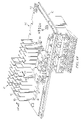
- FIG. 4A is an isometric drawing showing two cards that are included within the Ethernet switch of FIG. 1B and associated cooling elements;
- FIG. 4B is an isometric drawing showing a CPU with copper uplink card of FIG. 4A ;
- FIG. 4C is an isometric drawing showing an alternative embodiment of the CPU with copper uplink card of FIG. 4A ;
- FIG. 4D is an isometric drawing showing the PHY card of FIG. 4A ;
- FIGS. 5A and 5B are elevated drawings showing details of clips used to secure heat sinks according to the teachings of the invention.
- FIGS. 1A through 5B of the drawings like numerals being used for like and corresponding parts of the various drawings.
- FIG. 1A is a block diagram illustrating an Ethernet switch 10 according to the teachings of the invention.
- Ethernet switch 10 receives a plurality of lines 12 at respective ports 14 .
- Ethernet switch 10 may selectively couple, or switch, each line 12 to another line 12 or to an uplink 18 through output ports 16 .
- Ethernet switches may be used in a variety of contexts to communicate voice and data to a desired location and may be located in a variety of locations, such as within a central office of a telecommunications carrier or within a manufacturing or industrial environment.
- Ethernet switch 10 may be oriented in a variety of fashions and thus it is not known which side of Ethernet switch 10 would be visible to a user. In contrast, because of the conventional layout of many central offices, it is well known which side of the Ethernet device would be visible to the particular user.
- the teachings of the invention recognize this and provide indications of the status of operation of Ethernet switch that are visible on more than just one side, allowing orientation of the Ethernet device according to the desires of the user. Additional details are described in conjunction with FIGS. 1B through 2C .
- FIG. 1B illustrates an isometric drawing of Ethernet switch 10 according to the teachings of the invention.
- the front 20 of Ethernet switch is illustrated.
- Shown on front 20 of Ethernet switch 10 are a plurality of RJ connectors, or ports, 22 , a console port 24 , two uplink ports 26 , a power connector 28 , and a plurality of light pipes 30 .
- Ethernet switch 10 also has a top side 32 , a right side 34 , a left side 36 , a back side 38 , and a bottom side 40 .
- An edge 46 is formed by front side 20 and bottom side 40 .
- Ethernet switch 10 Formed on the various sides of Ethernet switch 10 are a plurality of apertures 42 for allowing cooling of Ethernet switch 10 .
- RJ ports 22 correspond to ports 14 of FIG. 1A .
- RJ ports 22 may each accept a RJ compatible line carrying voice or data traffic.
- Console port 24 allows connection to a console for controlling Ethernet switch 10 .
- Link ports 26 provide a connection to another device, such as a router, connected to Ethernet switch 10 .
- Connector 28 provides a location for providing power to Ethernet switch 10 as well as providing a location for user access to the relay connections.
- Light pipes 30 provide an indication of the operation of Ethernet switch 10 .
- light pipes 30 are provided such that they are visible both when Ethernet switch 10 rests on bottom side 40 as well as when it rests on front side 20 (as shown in FIG. 1C ).
- an indication of the operation of Ethernet switch 10 may be provided in either configuration. Additional details of light pipes 30 are provided below in conjunction with FIGS. 1C through 2D .
- FIG. 1C is an isometric drawing of Ethernet switch 10 shown in an alternative orientation. In this orientation, Ethernet switch 10 rests on front side 20 . Note that in this configuration, the left and right sides are reversed, as compared to FIG. 1B . Thus, left side 36 is visible in this view.
- This configuration represents a second installation orientation of Ethernet device 10 with the other likely installation orientation shown in FIG. 1B . Also illustrated in this view is a mounting clip 48 , which may be utilized to mount Ethernet switch 10 to DIN rails A plurality of mounting apertures, such as mounting apertures 44 , are also formed in back side 38 , but are obscured from view by mounting clip 48 .
- FIG. 2A is an isometric drawing of portions of the interior of Ethernet switch 10 according to the teachings of the invention. Shown is a PHY card 50 , which has attached thereto ports 22 , light pipes 30 , heat sinks 52 , and a physical device chip 54 . Heat sinks 52 help cool Ethernet switch 10 as warm air flows across the surface of heat sinks 52 , as described in greater detail below. Physical device chip 54 provides necessary functionality for receiving and transmitting signals through ports 22 . A clip 56 is provided to secure heat sinks 52 to PHY card 50 , and is described in greater detail below. Underneath light pipes 30 are a plurality of light emitting diodes 23 that are indicative of the operating state of particular one of ports 22 or other portions of Ethernet switch 10 . Conventionally, light generated by such LEDs could only be viewed from one side of an Ethernet switch.
- FIG. 2B illustrates light pipes 30 in greater detail.
- Light pipes 30 are connected to a base 60 and are formed with an end portion 62 and a base portion 64 .
- On end portion 62 is a light emitting region 66 through which light passes to provide an indication of the operation of Ethernet switch 10 .
- base portion 64 overlies light emitting diodes 23 (not explicitly shown) that are indicative of the operation of each of ports 22 , or alternatively, indicative of the operation of other functions of Ethernet switch 10 , including ports 26 , power connector 28 , and other operations of Ethernet switch 10 .
- FIG. 2C illustrates a reverse view of light pipes 30 .
- FIG. 2D is a side view a single light pipe 30 . Illustrated in FIG. 2D is an inclined portion 68 . Illustrated in FIG. 2D is an inclined portion 68 . Inclined portion 68 reflects light incident upon it towards light emitting regions 66 . In particular, light is reflected onto horizontal portion 70 of light emitting region 66 . Light reflected by portions of light pipe 30 may travel through portion 72 of light emitting region 66 without significant reflection from inclined portion 68 . Thus inclined portion 68 is provided such that light may emit from light emitting region 66 in generally different directions, thus allowing viewing of light indicative of the operation of Ethernet switch 10 on both the front 20 of Ethernet switch 10 (as illustrated in FIG. 1B ) and the bottom 40 of Ethernet switch 10 (as illustrated in FIG. 1C ).
- light pipe 30 is formed from GE Lexan type 201-112 material.
- light emitting portions 66 may be formed a textured surface, meaning that it diffuses light.
- all exterior surfaces of light pipes 30 are manufactured according to SPE/SPI Number 1. This is a standard surface finish callout for plastics that is machined into the production tool.
- light emitting regions 66 including portions 70 and 72 may be coated according to class B Cisco cosmetic spec 700474-0000, or Cisco Systems standard quality control spec for plastic products.
- the status of operation of Ethernet switch 10 may be made known to a user located either in the direction of the bottom of Ethernet switch 10 or the front of Ethernet switch 10 .
- Such an indication in a plurality of directions allows configuration during installation of Ethernet switch 10 such that it may rest on its bottom side or its front side, as described by the user.
- FIG. 3 is an isometric drawing showing portions of Ethernet switch 10 according to the teachings of the invention.
- portions of Ethernet switch 10 are deleted so as to render visible spacers 80 .
- Spacers 80 are formed from a generally thermally conductive material, such as aluminum, and operate to both physically support internal cards that perform the main functions of the Ethernet switch as well, as thermally conduct heat from the cards to bottom 40 of the housing of Ethernet switch 10 .
- heat that is generated by Ethernet switch and transferred to the cards, such as cards 50 or 82 FIG. 4A
- This is one cooling approach utilized by the teachings of the invention.
- Other approaches are described in greater detail below in conjunction with FIGS. 4A through 5B .
- the housing of Ethernet switch 10 is formed with a plurality of apertures 42 .
- Apertures 42 are designed to maximize the surface area of the apertures along the housing of Ethernet switch 10 to allow for heat transfer to the outside atmosphere but at the same time meet electromagnetic emission requirements.
- FIG. 4A is an isometric drawing showing cards 50 and 82 as they would appear positioned within housing of Ethernet switch 10 .
- Card 50 is a PHY card, described above, which includes a plurality of ports and light pipes for indicating the status of the ports or other operations within Ethernet switch 10 , as described above.
- Card 82 is a CPU with copper uplinks card and houses the CPU control, an ethernet switch and two alarm relays for external signaling. Disposed on both card 82 and card 50 (see FIG. 4D ) are various cooling devices for dissipating heat generated by Ethernet switch 10 . As described above, because of the environment in which industrial Ethernet switches are often utilized, passive cooling is required, and thus no convection fans are allowed. This restraint creates challenges for the designer in terms of heat dissipation.
- Heat sinks 84 are also illustrated in FIG. 4A .
- Heat sinks 84 are coupled to card 82 through a plurality of elastic clips 86 .
- Elastic clips 86 are shown best in FIG. 5A .
- Heat sinks 84 are formed with a base portion 88 and a fin portion 90 . Disposed between base portion 88 and card 82 (or component on card 82 ) is a phase change material that changes from a solid to a fluid as it is heated.
- the thermal interface material is Thermagon HP105, which changes from solid to liquid phases at approximately 60-65 degrees C. However, other interface materials that change phase from solid to liquid may be used.
- Elastic clips 86 operate to provide an elastic force on base 88 of heat sinks 84 (better illustrated in FIG. 5A ).
- Clips 86 work in conjunction with the phase change material 94 to provide a more conductive path for heat to transfer from components on card 82 to the atmosphere.
- clips 86 reduce any space created as the thermal interface material 94 goes through a phase change.
- a good thermal contact is maintained between components to be cooled and heat sinks 84 .
- the conventional fastener such as screw, would not necessarily maintain good contact between heat sinks 84 and component overlying card 82 as the thermal interface material changes phase. This is because a pin would not provide sufficient pressure when interface material goes through a phase change.
- heat sinks 84 are formed from a relatively lightweight material, such as aluminum. However, other materials may be used. The use of a lightweight material both allows better cooling, due to reduced thermal mass and therefore the reduced time to heat fins 90 , as well as providing lower inertia, which produces desirable vibration characteristics.
- the lighter weight heat sinks 84 reach thermal equilibrium quicker than more robust sinks and hence radiate and transfer the heat from the component more rapidly. This maintains a cooler component.
- heat generated on a component under heat sinks 84 is conducted through phase change material 94 to base 88 of heat sinks 84 .
- the heat then conducts to fins 90 where, in the illustrated orientation, the predominant heat transfer mechanism is radiation, and fins 90 radiate heat toward housing of Ethernet switch 10 .
- the predominant heat transfer mechanism is free convection, also known as a chimney effect, and heat transfer occurs through the slow movement of air over fins 90 , taking the heat to the housing of Ethernet switch 10 .
- spacers 80 ( FIG. 3 ) support cards 82 and 50 through fasteners 50 and also provide conduction directly from card 82 and 50 to the bottom 40 of Ethernet switch 10 . This provides additional heat transfer directly from the cards to the housing of Ethernet switch 10 .
- FIG. 4B shows more clearly card 82 .
- each of the fins 90 of the heat sinks 84 has a height of approximately 1.4 inches, as indicated by reference numeral 100 .
- Fins 84 also have an approximate width of 0.60 inches as indicated by reference numeral 102 , and are formed with a thickness of approximately 0.03 inches, as indicated by reference numeral 104 .
- Base 88 is formed with a thickness of approximately 0.9 inches, as indicated by reference numeral 106 .
- the various fins within a given heat sink are spaced apart approximately 0.3 inches as indicated by reference numeral 108 .
- FIG. 4C is an alternative embodiment of card 82 . In this embodiment, a lesser number of fins is utilized to accommodate additional components on card 82 b.
- FIG. 4D shows a bottom view of card 50 .
- card 50 includes a plurality of heat sinks 52 attached to card 50 via clips 56 .
- Heat sinks 52 are substantially similar to heat sinks 84 , except they are oriented differently and have different dimensions.
- fins 90 have a length of 1.5 inches, as designed by reference numeral 110 and a height of 1.31 inches as designated by reference numeral 112 . Fins 90 are formed with a thickness of 0.030 inches as designated by reference numeral 118 and base 115 is formed with a thickness of 0.090 inches as designated by reference numeral 116 .
- fins 90 are spaced apart by a distance of 0.304 inches, as designated by reference numeral 119 with an irregular spacing of 0.75 inches, as designated by reference numeral 120 to accommodate the board layout.
- clip 56 which is substantially similar to clip 86 , depresses against base 115 of heat sinks 52 between fins 90 . This contrasts with card 82 in which clips 86 depress against base 88 between rows of fins 90 .
- thermal vias may be formed within cards 50 and 82 to further allow heat transfer within Ethernet switch 10 .
- FIGS. 5A and 5B are partial elevational views of FIGS. 4B and 4D , respectively, along the indicated lines, showing clips 86 and 56 .
- clip 86 is illustrated as having a shape in the general configuration of an M with two side portions 95 and a middle portion 96 . On the ends of side portions 95 are hooks 97 for coupling clip 86 to card 82 .
- Clips 86 may also be formed with holes 99 for receiving a tool for attaching clips 86 to card 82 .
- middle portion 96 overlies a base 88 of heat sinks 84 .
- Below base 88 is a phase change material 93 , described above, which fills voids between base 88 and a component 120 overlying card 82 .
- Clip 56 of FIG. 5B is analogous to clip 86 except that it is disposed between two fins 90 of heat sinks 90 , rather than a cut across the heat sink fins.
Abstract
Description
Claims (23)
Priority Applications (6)
| Application Number | Priority Date | Filing Date | Title |
|---|---|---|---|
| US10/377,189 US7277295B2 (en) | 2003-02-28 | 2003-02-28 | Industrial ethernet switch |
| PCT/US2004/005823 WO2004079974A2 (en) | 2003-02-28 | 2004-02-24 | Industrial ethernet switch |
| EP04714229A EP1597950B1 (en) | 2003-02-28 | 2004-02-24 | Industrial ethernet switch |
| CN2004800051101A CN1754410B (en) | 2003-02-28 | 2004-02-24 | Industrial Ethernet switch |
| AT04714229T ATE506841T1 (en) | 2003-02-28 | 2004-02-24 | INDUSTRIAL ETHERNET EXCHANGE |
| DE602004032315T DE602004032315D1 (en) | 2003-02-28 | 2004-02-24 | INDUSTRIAL ETHERNET AGENCY |
Applications Claiming Priority (1)
| Application Number | Priority Date | Filing Date | Title |
|---|---|---|---|
| US10/377,189 US7277295B2 (en) | 2003-02-28 | 2003-02-28 | Industrial ethernet switch |
Publications (2)
| Publication Number | Publication Date |
|---|---|
| US20040170004A1 US20040170004A1 (en) | 2004-09-02 |
| US7277295B2 true US7277295B2 (en) | 2007-10-02 |
Family
ID=32908084
Family Applications (1)
| Application Number | Title | Priority Date | Filing Date |
|---|---|---|---|
| US10/377,189 Expired - Lifetime US7277295B2 (en) | 2003-02-28 | 2003-02-28 | Industrial ethernet switch |
Country Status (2)
| Country | Link |
|---|---|
| US (1) | US7277295B2 (en) |
| CN (1) | CN1754410B (en) |
Cited By (7)
| Publication number | Priority date | Publication date | Assignee | Title |
|---|---|---|---|---|
| US7903541B2 (en) | 2003-02-28 | 2011-03-08 | Cisco Technology, Inc. | Ethernet switch with configurable alarms |
| US8496488B2 (en) | 2011-03-24 | 2013-07-30 | Cisco Technology, Inc. | Power input terminal block housing and cover |
| US10849245B2 (en) | 2002-10-22 | 2020-11-24 | Atd Ventures, Llc | Systems and methods for providing a robust computer processing unit |
| USD904362S1 (en) * | 2019-02-25 | 2020-12-08 | Dell Products L.P. | Information handling system IoT gateway |
| USD904317S1 (en) * | 2019-04-08 | 2020-12-08 | Lsis Co., Ltd. | Input-and-output device for networks |
| USD918882S1 (en) * | 2018-08-23 | 2021-05-11 | Siemens Canada Limited | Network switch |
| USD922365S1 (en) * | 2019-02-22 | 2021-06-15 | Ambit Microsystems (Shanghai) Ltd. | Smart gateway |
Families Citing this family (12)
| Publication number | Priority date | Publication date | Assignee | Title |
|---|---|---|---|---|
| WO2004038526A2 (en) | 2002-10-22 | 2004-05-06 | Isys Technologies | Non-peripherals processing control module having improved heat dissipating properties |
| KR101197513B1 (en) | 2002-10-22 | 2012-11-09 | 제이슨 에이. 설리반 | Systems and methods for providing a dynamically modular processing unit |
| US7653283B2 (en) * | 2007-10-31 | 2010-01-26 | Cisco Technology, Inc. | Light pipe mounting interface |
| CN101674201B (en) * | 2009-10-30 | 2012-05-30 | 迈普通信技术股份有限公司 | Method for actively triggering active standby switch of Ethernet switch clustering |
| US20130264919A1 (en) * | 2010-06-07 | 2013-10-10 | Jason A. Sullivan | Systems and methods for mounting dynamically modular processing units |
| CN102546719B (en) * | 2010-12-31 | 2016-10-26 | 研祥智能科技股份有限公司 | A kind of network remote control system, method and Node station |
| CN103095588B (en) * | 2013-01-17 | 2015-09-30 | 清华大学 | Based on the adaptive routing method without dead of multiple spanning tree |
| CN103916292B (en) * | 2014-04-14 | 2017-02-15 | 贵州电力试验研究院 | digital substation switch online monitoring system based on IEC61850 standard |
| CN105933249A (en) * | 2016-06-28 | 2016-09-07 | 成都启源电子信息技术有限公司 | Automatic detection system for Ethernet switch |
| CN107508769A (en) * | 2017-08-25 | 2017-12-22 | 南京南业电子科技有限公司 | A kind of non-damageable industrial ethernet switch equipment in port |
| US10849253B2 (en) * | 2017-09-28 | 2020-11-24 | Hewlett Packard Enterprise Development Lp | Interconnected modular server and cooling means |
| CN110267466A (en) * | 2019-06-10 | 2019-09-20 | 中航(深圳)航电科技发展有限公司 | A kind of control box |
Citations (47)
| Publication number | Priority date | Publication date | Assignee | Title |
|---|---|---|---|---|
| US3696210A (en) | 1970-08-06 | 1972-10-03 | Motorola Inc | Data transferring system utilizing a monitor channel and logic circuitry to assure secure data communication |
| US4045624A (en) | 1976-04-02 | 1977-08-30 | Carrier Telephone Corporation Of America, Inc. | Continuous monitoring in carrier telephone systems |
| US4388715A (en) | 1979-08-03 | 1983-06-14 | Compagnie Industrielle Des Telecommunications Cit-Alcatel | Alarm preprocessor logic |
| US4660194A (en) | 1984-04-05 | 1987-04-21 | New York Telephone Company | Method and apparatus for testing a subscriber's line circuit in a packet switched multiplexed data/voice communication system |
| US5615224A (en) | 1995-01-04 | 1997-03-25 | The Regents Of The University Of California | Apparatus and method for stabilization of the bandgap and associated properties of semiconductor electronic and optoelectronic devices |
| US5651260A (en) | 1995-02-09 | 1997-07-29 | Matsushita Electric Industrial Co., Ltd. | Control apparatus and method for actuating an electrically driven compressor used in an air conditioning system of an automotive vehicle |
| GB2310086A (en) | 1996-02-09 | 1997-08-13 | 3Com Limited | Enclosure having a domed cover providing a vent |
| US5714938A (en) | 1996-11-19 | 1998-02-03 | Cae Electronics Ltd. | Temperature protection device for air cooled electronics housing |
| US5764482A (en) * | 1996-07-24 | 1998-06-09 | Thermacore, Inc. | Integrated circuit heat seat |
| US5771274A (en) | 1996-06-21 | 1998-06-23 | Mci Communications Corporation | Topology-based fault analysis in telecommunications networks |
| US5793922A (en) | 1994-10-17 | 1998-08-11 | Samsung Electronics Co., Ltd. | Channel code input and reproduction method of frame switcher and channel code reproduction apparatus |
| US5825618A (en) * | 1995-10-26 | 1998-10-20 | The Whitaker Corporation | Hub for a communications network |
| US5898557A (en) | 1996-07-30 | 1999-04-27 | Yazaki Corporation | Switching apparatus |
| US5920264A (en) | 1994-06-08 | 1999-07-06 | Samsung Electronics Co., Ltd. | Computer system protection device |
| US5973922A (en) * | 1998-04-30 | 1999-10-26 | Ncr Corporation | Apparatus and method of securing a heat dissipating cover to a thermally conductive housing associated with a retail terminal |
| US6005700A (en) * | 1996-06-26 | 1999-12-21 | Aironet Wireless Communications, Inc. | Computer peripheral device with detachable portion and light display |
| US6175501B1 (en) | 1998-12-31 | 2001-01-16 | Lucent Technologies Inc. | Method and arrangement for cooling an electronic assembly |
| WO2002017039A2 (en) | 2000-08-21 | 2002-02-28 | Woodhead Industries, Inc. | Industrial switching hub for ethernet network |
| WO2002023676A1 (en) | 2000-09-12 | 2002-03-21 | Tyco Electronics Amp Gmbh | Modular connection system for ethernet applications in the industrial sector |
| US6381214B1 (en) * | 1998-10-09 | 2002-04-30 | Texas Instruments Incorporated | Memory-efficient leaky bucket policer for traffic management of asynchronous transfer mode data communications |
| US6411506B1 (en) | 2000-07-20 | 2002-06-25 | Rlx Technologies, Inc. | High density web server chassis system and method |
| US20020104030A1 (en) | 2001-01-31 | 2002-08-01 | Hee-Geol Ahn | ACPI compliant computer system and overtemperature protection method therefor |
| US20020124114A1 (en) | 2001-03-05 | 2002-09-05 | Bottom David A. | Modular server architecture with ethernet routed across a backplane utilizing an integrated ethernet switch module |
| US6452809B1 (en) * | 2000-11-10 | 2002-09-17 | Galactic Computing Corporation | Scalable internet engine |
| US20020135601A1 (en) | 1997-06-02 | 2002-09-26 | Sony Corporation | Digital map display zooming method, digital map display zooming device, and storage medium for storing digital map display zooming program |
| US6496118B1 (en) | 2001-09-11 | 2002-12-17 | Warren L. Smith | Computer chip heat protection apparatus |
| US20020194412A1 (en) | 2001-06-13 | 2002-12-19 | Bottom David A. | Modular server architecture |
| US6549689B2 (en) | 2000-11-24 | 2003-04-15 | Hitachi Metals, Ltd. | Optical switch |
| US20030081604A1 (en) | 2001-10-29 | 2003-05-01 | Danner Phillip A. | Ethernet switch |
| US20030081620A1 (en) | 2001-10-29 | 2003-05-01 | Danner Phillip A. | Ethernet switch and system |
| US20030123453A1 (en) | 2001-12-10 | 2003-07-03 | Alcatel | Method and apparatus of directing multicast traffic in an Ethernet MAN |
| US20030135601A1 (en) | 2002-01-02 | 2003-07-17 | Pozzuoli Marzio Paride | Environmentally hardened ethernet switch |
| US20030163561A1 (en) | 2002-02-22 | 2003-08-28 | D-Link Corporation | Environment monitoring system for monitoring environment for installing community ethernet switch |
| US6632008B2 (en) * | 2001-11-09 | 2003-10-14 | Adc Broadband Access Systems, Inc. | Light-pipe |
| US6633998B1 (en) | 1999-12-13 | 2003-10-14 | General Electric Company | Multiple communications port unit and computer architecture |
| US6636499B1 (en) | 1999-12-02 | 2003-10-21 | Cisco Technology, Inc. | Apparatus and method for cluster network device discovery |
| US6636478B1 (en) | 2000-05-03 | 2003-10-21 | Metro Optix, Inc. | Configurable scalable communications equipment protection method system |
| US6644395B1 (en) * | 1999-11-17 | 2003-11-11 | Parker-Hannifin Corporation | Thermal interface material having a zone-coated release linear |
| US6661772B2 (en) | 1999-12-20 | 2003-12-09 | Kabushiki Kaisha Toshiba | Digital signal transmission apparatus |
| US6724635B2 (en) | 2001-08-07 | 2004-04-20 | Hewlett-Packard Development Company, L.P. | LCD panel for a server system |
| US20040095720A1 (en) | 2002-11-14 | 2004-05-20 | Packetfront Sweden Ab | Fan-less housing |
| US6754085B2 (en) * | 2001-09-28 | 2004-06-22 | Adc Broadband Access Systems, Inc. | Mounting circuit boards in housings |
| US6780047B1 (en) * | 2000-03-24 | 2004-08-24 | Intel Corporation | Network communications system |
| US20040179470A1 (en) | 2003-02-28 | 2004-09-16 | Nguyen Yen Teresa | Industrial ethernet switch |
| US6798744B1 (en) * | 1999-05-14 | 2004-09-28 | Pmc-Sierra, Inc. | Method and apparatus for interconnection of flow-controlled communication |
| US6808289B2 (en) * | 2001-07-20 | 2004-10-26 | RPM Optoelectronics, LLC | Method and apparatus for flexible led lamp |
| US6835453B2 (en) * | 2001-01-22 | 2004-12-28 | Parker-Hannifin Corporation | Clean release, phase change thermal interface |
-
2003
- 2003-02-28 US US10/377,189 patent/US7277295B2/en not_active Expired - Lifetime
-
2004
- 2004-02-24 CN CN2004800051101A patent/CN1754410B/en not_active Expired - Lifetime
Patent Citations (49)
| Publication number | Priority date | Publication date | Assignee | Title |
|---|---|---|---|---|
| US3696210A (en) | 1970-08-06 | 1972-10-03 | Motorola Inc | Data transferring system utilizing a monitor channel and logic circuitry to assure secure data communication |
| US4045624A (en) | 1976-04-02 | 1977-08-30 | Carrier Telephone Corporation Of America, Inc. | Continuous monitoring in carrier telephone systems |
| US4388715A (en) | 1979-08-03 | 1983-06-14 | Compagnie Industrielle Des Telecommunications Cit-Alcatel | Alarm preprocessor logic |
| US4660194A (en) | 1984-04-05 | 1987-04-21 | New York Telephone Company | Method and apparatus for testing a subscriber's line circuit in a packet switched multiplexed data/voice communication system |
| US5920264A (en) | 1994-06-08 | 1999-07-06 | Samsung Electronics Co., Ltd. | Computer system protection device |
| US5793922A (en) | 1994-10-17 | 1998-08-11 | Samsung Electronics Co., Ltd. | Channel code input and reproduction method of frame switcher and channel code reproduction apparatus |
| US5615224A (en) | 1995-01-04 | 1997-03-25 | The Regents Of The University Of California | Apparatus and method for stabilization of the bandgap and associated properties of semiconductor electronic and optoelectronic devices |
| US5651260A (en) | 1995-02-09 | 1997-07-29 | Matsushita Electric Industrial Co., Ltd. | Control apparatus and method for actuating an electrically driven compressor used in an air conditioning system of an automotive vehicle |
| US5825618A (en) * | 1995-10-26 | 1998-10-20 | The Whitaker Corporation | Hub for a communications network |
| GB2310086A (en) | 1996-02-09 | 1997-08-13 | 3Com Limited | Enclosure having a domed cover providing a vent |
| US5771274A (en) | 1996-06-21 | 1998-06-23 | Mci Communications Corporation | Topology-based fault analysis in telecommunications networks |
| US6005700A (en) * | 1996-06-26 | 1999-12-21 | Aironet Wireless Communications, Inc. | Computer peripheral device with detachable portion and light display |
| US5764482A (en) * | 1996-07-24 | 1998-06-09 | Thermacore, Inc. | Integrated circuit heat seat |
| US5898557A (en) | 1996-07-30 | 1999-04-27 | Yazaki Corporation | Switching apparatus |
| US5714938A (en) | 1996-11-19 | 1998-02-03 | Cae Electronics Ltd. | Temperature protection device for air cooled electronics housing |
| US20020135601A1 (en) | 1997-06-02 | 2002-09-26 | Sony Corporation | Digital map display zooming method, digital map display zooming device, and storage medium for storing digital map display zooming program |
| US5973922A (en) * | 1998-04-30 | 1999-10-26 | Ncr Corporation | Apparatus and method of securing a heat dissipating cover to a thermally conductive housing associated with a retail terminal |
| US6381214B1 (en) * | 1998-10-09 | 2002-04-30 | Texas Instruments Incorporated | Memory-efficient leaky bucket policer for traffic management of asynchronous transfer mode data communications |
| US6175501B1 (en) | 1998-12-31 | 2001-01-16 | Lucent Technologies Inc. | Method and arrangement for cooling an electronic assembly |
| US6798744B1 (en) * | 1999-05-14 | 2004-09-28 | Pmc-Sierra, Inc. | Method and apparatus for interconnection of flow-controlled communication |
| US6644395B1 (en) * | 1999-11-17 | 2003-11-11 | Parker-Hannifin Corporation | Thermal interface material having a zone-coated release linear |
| US6636499B1 (en) | 1999-12-02 | 2003-10-21 | Cisco Technology, Inc. | Apparatus and method for cluster network device discovery |
| US6633998B1 (en) | 1999-12-13 | 2003-10-14 | General Electric Company | Multiple communications port unit and computer architecture |
| US6661772B2 (en) | 1999-12-20 | 2003-12-09 | Kabushiki Kaisha Toshiba | Digital signal transmission apparatus |
| US6780047B1 (en) * | 2000-03-24 | 2004-08-24 | Intel Corporation | Network communications system |
| US6636478B1 (en) | 2000-05-03 | 2003-10-21 | Metro Optix, Inc. | Configurable scalable communications equipment protection method system |
| US6411506B1 (en) | 2000-07-20 | 2002-06-25 | Rlx Technologies, Inc. | High density web server chassis system and method |
| US6853316B2 (en) | 2000-08-21 | 2005-02-08 | Woodhead Industries, Inc. | Industrial switching hub for Ethernet network |
| WO2002017039A2 (en) | 2000-08-21 | 2002-02-28 | Woodhead Industries, Inc. | Industrial switching hub for ethernet network |
| US20020025710A1 (en) | 2000-08-21 | 2002-02-28 | Payson Brian D. | Industrial switching hub for ethernet network |
| WO2002023676A1 (en) | 2000-09-12 | 2002-03-21 | Tyco Electronics Amp Gmbh | Modular connection system for ethernet applications in the industrial sector |
| US6452809B1 (en) * | 2000-11-10 | 2002-09-17 | Galactic Computing Corporation | Scalable internet engine |
| US6549689B2 (en) | 2000-11-24 | 2003-04-15 | Hitachi Metals, Ltd. | Optical switch |
| US6835453B2 (en) * | 2001-01-22 | 2004-12-28 | Parker-Hannifin Corporation | Clean release, phase change thermal interface |
| US20020104030A1 (en) | 2001-01-31 | 2002-08-01 | Hee-Geol Ahn | ACPI compliant computer system and overtemperature protection method therefor |
| US20020124114A1 (en) | 2001-03-05 | 2002-09-05 | Bottom David A. | Modular server architecture with ethernet routed across a backplane utilizing an integrated ethernet switch module |
| US20020194412A1 (en) | 2001-06-13 | 2002-12-19 | Bottom David A. | Modular server architecture |
| US6808289B2 (en) * | 2001-07-20 | 2004-10-26 | RPM Optoelectronics, LLC | Method and apparatus for flexible led lamp |
| US6724635B2 (en) | 2001-08-07 | 2004-04-20 | Hewlett-Packard Development Company, L.P. | LCD panel for a server system |
| US6496118B1 (en) | 2001-09-11 | 2002-12-17 | Warren L. Smith | Computer chip heat protection apparatus |
| US6754085B2 (en) * | 2001-09-28 | 2004-06-22 | Adc Broadband Access Systems, Inc. | Mounting circuit boards in housings |
| US20030081620A1 (en) | 2001-10-29 | 2003-05-01 | Danner Phillip A. | Ethernet switch and system |
| US20030081604A1 (en) | 2001-10-29 | 2003-05-01 | Danner Phillip A. | Ethernet switch |
| US6632008B2 (en) * | 2001-11-09 | 2003-10-14 | Adc Broadband Access Systems, Inc. | Light-pipe |
| US20030123453A1 (en) | 2001-12-10 | 2003-07-03 | Alcatel | Method and apparatus of directing multicast traffic in an Ethernet MAN |
| US20030135601A1 (en) | 2002-01-02 | 2003-07-17 | Pozzuoli Marzio Paride | Environmentally hardened ethernet switch |
| US20030163561A1 (en) | 2002-02-22 | 2003-08-28 | D-Link Corporation | Environment monitoring system for monitoring environment for installing community ethernet switch |
| US20040095720A1 (en) | 2002-11-14 | 2004-05-20 | Packetfront Sweden Ab | Fan-less housing |
| US20040179470A1 (en) | 2003-02-28 | 2004-09-16 | Nguyen Yen Teresa | Industrial ethernet switch |
Non-Patent Citations (3)
| Title |
|---|
| PCT Invitation to Pay Additional Fees (PCT Article 17(3)(a) and Rule 40.1); mailed Aug. 23, 2004 Re: PCT/US2004/005823; filed Feb. 24, 2004 (6 pgs.). |
| U.S. Appl. No. 10/377,066, filed Feb. 28, 2003, entitled "Ethernet Switch With Configurable Alarms", 37 pages of text and 10 pages of drawings. |
| U.S. Appl. No. 10/377,570, filed Feb. 28, 2003, entitled "Industrial Ethernet Switch", 39 pages of text and 10 pages of drawings. |
Cited By (10)
| Publication number | Priority date | Publication date | Assignee | Title |
|---|---|---|---|---|
| US10849245B2 (en) | 2002-10-22 | 2020-11-24 | Atd Ventures, Llc | Systems and methods for providing a robust computer processing unit |
| US11751350B2 (en) | 2002-10-22 | 2023-09-05 | Atd Ventures, Llc | Systems and methods for providing a robust computer processing unit |
| US7903541B2 (en) | 2003-02-28 | 2011-03-08 | Cisco Technology, Inc. | Ethernet switch with configurable alarms |
| US8496488B2 (en) | 2011-03-24 | 2013-07-30 | Cisco Technology, Inc. | Power input terminal block housing and cover |
| US8632359B2 (en) | 2011-03-24 | 2014-01-21 | Cisco Technology, Inc. | Power input terminal block housing and cover |
| USD918882S1 (en) * | 2018-08-23 | 2021-05-11 | Siemens Canada Limited | Network switch |
| USD922365S1 (en) * | 2019-02-22 | 2021-06-15 | Ambit Microsystems (Shanghai) Ltd. | Smart gateway |
| USD991929S1 (en) * | 2019-02-22 | 2023-07-11 | Ambit Microsystems (Shanghai) Ltd. | Smart gateway |
| USD904362S1 (en) * | 2019-02-25 | 2020-12-08 | Dell Products L.P. | Information handling system IoT gateway |
| USD904317S1 (en) * | 2019-04-08 | 2020-12-08 | Lsis Co., Ltd. | Input-and-output device for networks |
Also Published As
| Publication number | Publication date |
|---|---|
| CN1754410B (en) | 2012-05-30 |
| CN1754410A (en) | 2006-03-29 |
| US20040170004A1 (en) | 2004-09-02 |
Similar Documents
| Publication | Publication Date | Title |
|---|---|---|
| US7277295B2 (en) | Industrial ethernet switch | |
| KR0156013B1 (en) | Heat sink and cover for tab integrated circuits | |
| US6466441B1 (en) | Cooling device of electronic part having high and low heat generating elements | |
| US9456527B2 (en) | Fabricating separable and integrated heat sinks facilitating cooling multi-component electronic assembly | |
| US5049982A (en) | Article comprising a stacked array of electronic subassemblies | |
| KR100286375B1 (en) | Radiator of electronic system and computer system having the same | |
| JPH0798195A (en) | Cooling module | |
| US7131487B2 (en) | Use of adjusted evaporator section area of heat pipe that is sized to match the surface area of an integrated heat spreader used in CPU packages in mobile computers | |
| KR100622793B1 (en) | Apparatus for cooling a box with heat generating elements received therein and a method for cooling same | |
| WO2003063568A1 (en) | Thermally enhanced interposer and method | |
| US7817424B2 (en) | Heat sink assembly including a heat pipe and a duct | |
| EP2363881A1 (en) | Heat-Dissipating Device for Supplying Cold Airflow | |
| US11910572B2 (en) | Sealed communications module with multi-path thermal management system | |
| JP2001015969A (en) | Cooling apparatus | |
| JP2005057070A (en) | Heat radiating structure of electronic equipment | |
| JPH10107192A (en) | Heat sink | |
| JP5056036B2 (en) | Heat dissipation structure for electronic component equipment | |
| JPH1098287A (en) | Cooler for circuit board module and portable electronic equipment having the cooler | |
| US7362584B2 (en) | Heat relief socket | |
| CN217486850U (en) | Vehicle-mounted host device and automobile | |
| JPH10256766A (en) | Forced air cooling structure for electronic apparatus | |
| CN219437482U (en) | Combined temperature control device of imaging unit | |
| CN212278660U (en) | Radiating assembly and remote controller | |
| CN216083379U (en) | Heat radiator | |
| CN209351605U (en) | Shock-damping structure and electronic equipment |
Legal Events
| Date | Code | Title | Description |
|---|---|---|---|
| AS | Assignment |
Owner name: CISCO TECHNOLOGY, INC., CALIFORNIA Free format text: ASSIGNMENT OF ASSIGNORS INTEREST;ASSIGNORS:ZIMMERMAN, CRAIG A.;BOONE, EARL W.;GRIMM, MATTHEW D.;AND OTHERS;REEL/FRAME:014377/0403 Effective date: 20030228 |
|
| STCF | Information on status: patent grant |
Free format text: PATENTED CASE |
|
| FPAY | Fee payment |
Year of fee payment: 4 |
|
| FPAY | Fee payment |
Year of fee payment: 8 |
|
| MAFP | Maintenance fee payment |
Free format text: PAYMENT OF MAINTENANCE FEE, 12TH YEAR, LARGE ENTITY (ORIGINAL EVENT CODE: M1553); ENTITY STATUS OF PATENT OWNER: LARGE ENTITY Year of fee payment: 12 |