US7278207B2 - Method of making an electronic package - Google Patents
Method of making an electronic package Download PDFInfo
- Publication number
- US7278207B2 US7278207B2 US11/182,167 US18216705A US7278207B2 US 7278207 B2 US7278207 B2 US 7278207B2 US 18216705 A US18216705 A US 18216705A US 7278207 B2 US7278207 B2 US 7278207B2
- Authority
- US
- United States
- Prior art keywords
- layer
- conductive
- hole
- electronic package
- substrate
- Prior art date
- Legal status (The legal status is an assumption and is not a legal conclusion. Google has not performed a legal analysis and makes no representation as to the accuracy of the status listed.)
- Expired - Fee Related, expires
Links
Images


Classifications
-
- H—ELECTRICITY
- H01—ELECTRIC ELEMENTS
- H01L—SEMICONDUCTOR DEVICES NOT COVERED BY CLASS H10
- H01L21/00—Processes or apparatus adapted for the manufacture or treatment of semiconductor or solid state devices or of parts thereof
- H01L21/02—Manufacture or treatment of semiconductor devices or of parts thereof
- H01L21/04—Manufacture or treatment of semiconductor devices or of parts thereof the devices having at least one potential-jump barrier or surface barrier, e.g. PN junction, depletion layer or carrier concentration layer
- H01L21/48—Manufacture or treatment of parts, e.g. containers, prior to assembly of the devices, using processes not provided for in a single one of the subgroups H01L21/06 - H01L21/326
- H01L21/4814—Conductive parts
- H01L21/4846—Leads on or in insulating or insulated substrates, e.g. metallisation
- H01L21/4857—Multilayer substrates
-
- H—ELECTRICITY
- H01—ELECTRIC ELEMENTS
- H01L—SEMICONDUCTOR DEVICES NOT COVERED BY CLASS H10
- H01L21/00—Processes or apparatus adapted for the manufacture or treatment of semiconductor or solid state devices or of parts thereof
- H01L21/02—Manufacture or treatment of semiconductor devices or of parts thereof
- H01L21/04—Manufacture or treatment of semiconductor devices or of parts thereof the devices having at least one potential-jump barrier or surface barrier, e.g. PN junction, depletion layer or carrier concentration layer
- H01L21/48—Manufacture or treatment of parts, e.g. containers, prior to assembly of the devices, using processes not provided for in a single one of the subgroups H01L21/06 - H01L21/326
- H01L21/4814—Conductive parts
- H01L21/4846—Leads on or in insulating or insulated substrates, e.g. metallisation
- H01L21/486—Via connections through the substrate with or without pins
-
- H—ELECTRICITY
- H01—ELECTRIC ELEMENTS
- H01L—SEMICONDUCTOR DEVICES NOT COVERED BY CLASS H10
- H01L23/00—Details of semiconductor or other solid state devices
- H01L23/12—Mountings, e.g. non-detachable insulating substrates
- H01L23/14—Mountings, e.g. non-detachable insulating substrates characterised by the material or its electrical properties
- H01L23/15—Ceramic or glass substrates
-
- H—ELECTRICITY
- H01—ELECTRIC ELEMENTS
- H01L—SEMICONDUCTOR DEVICES NOT COVERED BY CLASS H10
- H01L23/00—Details of semiconductor or other solid state devices
- H01L23/48—Arrangements for conducting electric current to or from the solid state body in operation, e.g. leads, terminal arrangements ; Selection of materials therefor
- H01L23/488—Arrangements for conducting electric current to or from the solid state body in operation, e.g. leads, terminal arrangements ; Selection of materials therefor consisting of soldered or bonded constructions
- H01L23/498—Leads, i.e. metallisations or lead-frames on insulating substrates, e.g. chip carriers
- H01L23/49811—Additional leads joined to the metallisation on the insulating substrate, e.g. pins, bumps, wires, flat leads
- H01L23/49816—Spherical bumps on the substrate for external connection, e.g. ball grid arrays [BGA]
-
- H—ELECTRICITY
- H01—ELECTRIC ELEMENTS
- H01L—SEMICONDUCTOR DEVICES NOT COVERED BY CLASS H10
- H01L23/00—Details of semiconductor or other solid state devices
- H01L23/48—Arrangements for conducting electric current to or from the solid state body in operation, e.g. leads, terminal arrangements ; Selection of materials therefor
- H01L23/488—Arrangements for conducting electric current to or from the solid state body in operation, e.g. leads, terminal arrangements ; Selection of materials therefor consisting of soldered or bonded constructions
- H01L23/498—Leads, i.e. metallisations or lead-frames on insulating substrates, e.g. chip carriers
- H01L23/49822—Multilayer substrates
-
- H—ELECTRICITY
- H01—ELECTRIC ELEMENTS
- H01L—SEMICONDUCTOR DEVICES NOT COVERED BY CLASS H10
- H01L23/00—Details of semiconductor or other solid state devices
- H01L23/48—Arrangements for conducting electric current to or from the solid state body in operation, e.g. leads, terminal arrangements ; Selection of materials therefor
- H01L23/488—Arrangements for conducting electric current to or from the solid state body in operation, e.g. leads, terminal arrangements ; Selection of materials therefor consisting of soldered or bonded constructions
- H01L23/498—Leads, i.e. metallisations or lead-frames on insulating substrates, e.g. chip carriers
- H01L23/49827—Via connections through the substrates, e.g. pins going through the substrate, coaxial cables
-
- H—ELECTRICITY
- H05—ELECTRIC TECHNIQUES NOT OTHERWISE PROVIDED FOR
- H05K—PRINTED CIRCUITS; CASINGS OR CONSTRUCTIONAL DETAILS OF ELECTRIC APPARATUS; MANUFACTURE OF ASSEMBLAGES OF ELECTRICAL COMPONENTS
- H05K1/00—Printed circuits
- H05K1/02—Details
- H05K1/0271—Arrangements for reducing stress or warp in rigid printed circuit boards, e.g. caused by loads, vibrations or differences in thermal expansion
-
- H—ELECTRICITY
- H05—ELECTRIC TECHNIQUES NOT OTHERWISE PROVIDED FOR
- H05K—PRINTED CIRCUITS; CASINGS OR CONSTRUCTIONAL DETAILS OF ELECTRIC APPARATUS; MANUFACTURE OF ASSEMBLAGES OF ELECTRICAL COMPONENTS
- H05K1/00—Printed circuits
- H05K1/02—Details
- H05K1/11—Printed elements for providing electric connections to or between printed circuits
- H05K1/111—Pads for surface mounting, e.g. lay-out
- H05K1/112—Pads for surface mounting, e.g. lay-out directly combined with via connections
- H05K1/113—Via provided in pad; Pad over filled via
-
- H—ELECTRICITY
- H05—ELECTRIC TECHNIQUES NOT OTHERWISE PROVIDED FOR
- H05K—PRINTED CIRCUITS; CASINGS OR CONSTRUCTIONAL DETAILS OF ELECTRIC APPARATUS; MANUFACTURE OF ASSEMBLAGES OF ELECTRICAL COMPONENTS
- H05K3/00—Apparatus or processes for manufacturing printed circuits
- H05K3/46—Manufacturing multilayer circuits
- H05K3/4602—Manufacturing multilayer circuits characterized by a special circuit board as base or central core whereon additional circuit layers are built or additional circuit boards are laminated
- H05K3/4605—Manufacturing multilayer circuits characterized by a special circuit board as base or central core whereon additional circuit layers are built or additional circuit boards are laminated made from inorganic insulating material
-
- H—ELECTRICITY
- H01—ELECTRIC ELEMENTS
- H01L—SEMICONDUCTOR DEVICES NOT COVERED BY CLASS H10
- H01L23/00—Details of semiconductor or other solid state devices
- H01L23/48—Arrangements for conducting electric current to or from the solid state body in operation, e.g. leads, terminal arrangements ; Selection of materials therefor
- H01L23/488—Arrangements for conducting electric current to or from the solid state body in operation, e.g. leads, terminal arrangements ; Selection of materials therefor consisting of soldered or bonded constructions
- H01L23/498—Leads, i.e. metallisations or lead-frames on insulating substrates, e.g. chip carriers
- H01L23/49866—Leads, i.e. metallisations or lead-frames on insulating substrates, e.g. chip carriers characterised by the materials
- H01L23/49894—Materials of the insulating layers or coatings
-
- H—ELECTRICITY
- H01—ELECTRIC ELEMENTS
- H01L—SEMICONDUCTOR DEVICES NOT COVERED BY CLASS H10
- H01L2924/00—Indexing scheme for arrangements or methods for connecting or disconnecting semiconductor or solid-state bodies as covered by H01L24/00
- H01L2924/0001—Technical content checked by a classifier
- H01L2924/0002—Not covered by any one of groups H01L24/00, H01L24/00 and H01L2224/00
-
- H—ELECTRICITY
- H05—ELECTRIC TECHNIQUES NOT OTHERWISE PROVIDED FOR
- H05K—PRINTED CIRCUITS; CASINGS OR CONSTRUCTIONAL DETAILS OF ELECTRIC APPARATUS; MANUFACTURE OF ASSEMBLAGES OF ELECTRICAL COMPONENTS
- H05K1/00—Printed circuits
- H05K1/02—Details
- H05K1/03—Use of materials for the substrate
- H05K1/0306—Inorganic insulating substrates, e.g. ceramic, glass
-
- H—ELECTRICITY
- H05—ELECTRIC TECHNIQUES NOT OTHERWISE PROVIDED FOR
- H05K—PRINTED CIRCUITS; CASINGS OR CONSTRUCTIONAL DETAILS OF ELECTRIC APPARATUS; MANUFACTURE OF ASSEMBLAGES OF ELECTRICAL COMPONENTS
- H05K2201/00—Indexing scheme relating to printed circuits covered by H05K1/00
- H05K2201/01—Dielectrics
- H05K2201/0104—Properties and characteristics in general
- H05K2201/0133—Elastomeric or compliant polymer
-
- H—ELECTRICITY
- H05—ELECTRIC TECHNIQUES NOT OTHERWISE PROVIDED FOR
- H05K—PRINTED CIRCUITS; CASINGS OR CONSTRUCTIONAL DETAILS OF ELECTRIC APPARATUS; MANUFACTURE OF ASSEMBLAGES OF ELECTRICAL COMPONENTS
- H05K2201/00—Indexing scheme relating to printed circuits covered by H05K1/00
- H05K2201/01—Dielectrics
- H05K2201/0137—Materials
- H05K2201/015—Fluoropolymer, e.g. polytetrafluoroethylene [PTFE]
-
- H—ELECTRICITY
- H05—ELECTRIC TECHNIQUES NOT OTHERWISE PROVIDED FOR
- H05K—PRINTED CIRCUITS; CASINGS OR CONSTRUCTIONAL DETAILS OF ELECTRIC APPARATUS; MANUFACTURE OF ASSEMBLAGES OF ELECTRICAL COMPONENTS
- H05K2201/00—Indexing scheme relating to printed circuits covered by H05K1/00
- H05K2201/09—Shape and layout
- H05K2201/09209—Shape and layout details of conductors
- H05K2201/09372—Pads and lands
- H05K2201/09436—Pads or lands on permanent coating which covers the other conductors
-
- H—ELECTRICITY
- H05—ELECTRIC TECHNIQUES NOT OTHERWISE PROVIDED FOR
- H05K—PRINTED CIRCUITS; CASINGS OR CONSTRUCTIONAL DETAILS OF ELECTRIC APPARATUS; MANUFACTURE OF ASSEMBLAGES OF ELECTRICAL COMPONENTS
- H05K2201/00—Indexing scheme relating to printed circuits covered by H05K1/00
- H05K2201/09—Shape and layout
- H05K2201/09209—Shape and layout details of conductors
- H05K2201/095—Conductive through-holes or vias
- H05K2201/09509—Blind vias, i.e. vias having one side closed
-
- H—ELECTRICITY
- H05—ELECTRIC TECHNIQUES NOT OTHERWISE PROVIDED FOR
- H05K—PRINTED CIRCUITS; CASINGS OR CONSTRUCTIONAL DETAILS OF ELECTRIC APPARATUS; MANUFACTURE OF ASSEMBLAGES OF ELECTRICAL COMPONENTS
- H05K2201/00—Indexing scheme relating to printed circuits covered by H05K1/00
- H05K2201/10—Details of components or other objects attached to or integrated in a printed circuit board
- H05K2201/10613—Details of electrical connections of non-printed components, e.g. special leads
- H05K2201/10621—Components characterised by their electrical contacts
- H05K2201/10734—Ball grid array [BGA]; Bump grid array
-
- H—ELECTRICITY
- H05—ELECTRIC TECHNIQUES NOT OTHERWISE PROVIDED FOR
- H05K—PRINTED CIRCUITS; CASINGS OR CONSTRUCTIONAL DETAILS OF ELECTRIC APPARATUS; MANUFACTURE OF ASSEMBLAGES OF ELECTRICAL COMPONENTS
- H05K2203/00—Indexing scheme relating to apparatus or processes for manufacturing printed circuits covered by H05K3/00
- H05K2203/06—Lamination
- H05K2203/061—Lamination of previously made multilayered subassemblies
-
- H—ELECTRICITY
- H05—ELECTRIC TECHNIQUES NOT OTHERWISE PROVIDED FOR
- H05K—PRINTED CIRCUITS; CASINGS OR CONSTRUCTIONAL DETAILS OF ELECTRIC APPARATUS; MANUFACTURE OF ASSEMBLAGES OF ELECTRICAL COMPONENTS
- H05K3/00—Apparatus or processes for manufacturing printed circuits
- H05K3/30—Assembling printed circuits with electric components, e.g. with resistor
- H05K3/32—Assembling printed circuits with electric components, e.g. with resistor electrically connecting electric components or wires to printed circuits
- H05K3/34—Assembling printed circuits with electric components, e.g. with resistor electrically connecting electric components or wires to printed circuits by soldering
- H05K3/341—Surface mounted components
- H05K3/3431—Leadless components
- H05K3/3436—Leadless components having an array of bottom contacts, e.g. pad grid array or ball grid array components
-
- H—ELECTRICITY
- H05—ELECTRIC TECHNIQUES NOT OTHERWISE PROVIDED FOR
- H05K—PRINTED CIRCUITS; CASINGS OR CONSTRUCTIONAL DETAILS OF ELECTRIC APPARATUS; MANUFACTURE OF ASSEMBLAGES OF ELECTRICAL COMPONENTS
- H05K3/00—Apparatus or processes for manufacturing printed circuits
- H05K3/30—Assembling printed circuits with electric components, e.g. with resistor
- H05K3/32—Assembling printed circuits with electric components, e.g. with resistor electrically connecting electric components or wires to printed circuits
- H05K3/34—Assembling printed circuits with electric components, e.g. with resistor electrically connecting electric components or wires to printed circuits by soldering
- H05K3/3457—Solder materials or compositions; Methods of application thereof
-
- H—ELECTRICITY
- H05—ELECTRIC TECHNIQUES NOT OTHERWISE PROVIDED FOR
- H05K—PRINTED CIRCUITS; CASINGS OR CONSTRUCTIONAL DETAILS OF ELECTRIC APPARATUS; MANUFACTURE OF ASSEMBLAGES OF ELECTRICAL COMPONENTS
- H05K3/00—Apparatus or processes for manufacturing printed circuits
- H05K3/40—Forming printed elements for providing electric connections to or between printed circuits
- H05K3/4038—Through-connections; Vertical interconnect access [VIA] connections
- H05K3/4053—Through-connections; Vertical interconnect access [VIA] connections by thick-film techniques
- H05K3/4069—Through-connections; Vertical interconnect access [VIA] connections by thick-film techniques for via connections in organic insulating substrates
-
- H—ELECTRICITY
- H05—ELECTRIC TECHNIQUES NOT OTHERWISE PROVIDED FOR
- H05K—PRINTED CIRCUITS; CASINGS OR CONSTRUCTIONAL DETAILS OF ELECTRIC APPARATUS; MANUFACTURE OF ASSEMBLAGES OF ELECTRICAL COMPONENTS
- H05K3/00—Apparatus or processes for manufacturing printed circuits
- H05K3/46—Manufacturing multilayer circuits
- H05K3/4644—Manufacturing multilayer circuits by building the multilayer layer by layer, i.e. build-up multilayer circuits
-
- H—ELECTRICITY
- H05—ELECTRIC TECHNIQUES NOT OTHERWISE PROVIDED FOR
- H05K—PRINTED CIRCUITS; CASINGS OR CONSTRUCTIONAL DETAILS OF ELECTRIC APPARATUS; MANUFACTURE OF ASSEMBLAGES OF ELECTRICAL COMPONENTS
- H05K3/00—Apparatus or processes for manufacturing printed circuits
- H05K3/46—Manufacturing multilayer circuits
- H05K3/4688—Composite multilayer circuits, i.e. comprising insulating layers having different properties
-
- Y—GENERAL TAGGING OF NEW TECHNOLOGICAL DEVELOPMENTS; GENERAL TAGGING OF CROSS-SECTIONAL TECHNOLOGIES SPANNING OVER SEVERAL SECTIONS OF THE IPC; TECHNICAL SUBJECTS COVERED BY FORMER USPC CROSS-REFERENCE ART COLLECTIONS [XRACs] AND DIGESTS
- Y10—TECHNICAL SUBJECTS COVERED BY FORMER USPC
- Y10T—TECHNICAL SUBJECTS COVERED BY FORMER US CLASSIFICATION
- Y10T29/00—Metal working
- Y10T29/49—Method of mechanical manufacture
- Y10T29/49002—Electrical device making
- Y10T29/49117—Conductor or circuit manufacturing
- Y10T29/49124—On flat or curved insulated base, e.g., printed circuit, etc.
- Y10T29/49128—Assembling formed circuit to base
-
- Y—GENERAL TAGGING OF NEW TECHNOLOGICAL DEVELOPMENTS; GENERAL TAGGING OF CROSS-SECTIONAL TECHNOLOGIES SPANNING OVER SEVERAL SECTIONS OF THE IPC; TECHNICAL SUBJECTS COVERED BY FORMER USPC CROSS-REFERENCE ART COLLECTIONS [XRACs] AND DIGESTS
- Y10—TECHNICAL SUBJECTS COVERED BY FORMER USPC
- Y10T—TECHNICAL SUBJECTS COVERED BY FORMER US CLASSIFICATION
- Y10T29/00—Metal working
- Y10T29/49—Method of mechanical manufacture
- Y10T29/49002—Electrical device making
- Y10T29/49117—Conductor or circuit manufacturing
- Y10T29/49124—On flat or curved insulated base, e.g., printed circuit, etc.
- Y10T29/4913—Assembling to base an electrical component, e.g., capacitor, etc.
-
- Y—GENERAL TAGGING OF NEW TECHNOLOGICAL DEVELOPMENTS; GENERAL TAGGING OF CROSS-SECTIONAL TECHNOLOGIES SPANNING OVER SEVERAL SECTIONS OF THE IPC; TECHNICAL SUBJECTS COVERED BY FORMER USPC CROSS-REFERENCE ART COLLECTIONS [XRACs] AND DIGESTS
- Y10—TECHNICAL SUBJECTS COVERED BY FORMER USPC
- Y10T—TECHNICAL SUBJECTS COVERED BY FORMER US CLASSIFICATION
- Y10T29/00—Metal working
- Y10T29/49—Method of mechanical manufacture
- Y10T29/49002—Electrical device making
- Y10T29/49117—Conductor or circuit manufacturing
- Y10T29/49124—On flat or curved insulated base, e.g., printed circuit, etc.
- Y10T29/49147—Assembling terminal to base
- Y10T29/49151—Assembling terminal to base by deforming or shaping
- Y10T29/49153—Assembling terminal to base by deforming or shaping with shaping or forcing terminal into base aperture
-
- Y—GENERAL TAGGING OF NEW TECHNOLOGICAL DEVELOPMENTS; GENERAL TAGGING OF CROSS-SECTIONAL TECHNOLOGIES SPANNING OVER SEVERAL SECTIONS OF THE IPC; TECHNICAL SUBJECTS COVERED BY FORMER USPC CROSS-REFERENCE ART COLLECTIONS [XRACs] AND DIGESTS
- Y10—TECHNICAL SUBJECTS COVERED BY FORMER USPC
- Y10T—TECHNICAL SUBJECTS COVERED BY FORMER US CLASSIFICATION
- Y10T29/00—Metal working
- Y10T29/49—Method of mechanical manufacture
- Y10T29/49002—Electrical device making
- Y10T29/49117—Conductor or circuit manufacturing
- Y10T29/49124—On flat or curved insulated base, e.g., printed circuit, etc.
- Y10T29/49155—Manufacturing circuit on or in base
- Y10T29/49165—Manufacturing circuit on or in base by forming conductive walled aperture in base
Definitions
- the present invention relates to an electrical interconnection arrangement for making connection between electronic substrates and, more particularly, to making electrical interconnection between a chip carrier and a printed wiring board.
- CTE coefficient of thermal expansion
- the CTE thermal mismatch is particularly large where a ceramic chip carrier substrate is connected to a printed wiring board typically made of an epoxy/glass material.
- the heat generated by the chip compounds the CTE mismatch problem between the chip carrier substrate and the printed wiring board because of large temperature variations between the chip and the printed wiring board.
- certain applications, such as flip chip applications have required encapsulation to ensure a reliable flip chip interconnection in the solder joints between the chip and the substrate.
- Such encapsulation typically employs a high strength epoxy which acts to reinforce the bond between the chip and the chip carrier substrate.
- a high strength epoxy acts to reinforce the bond between the chip and the chip carrier substrate.
- this reinforcing of the chip to chip carrier substrate reduces solder joint stress between the chip and the chip carrier.
- this reinforcement can cause high stress between the ceramic chip carrier substrate and the printed wiring board to which it is attached. Repeated thermal cycling can lead to cracking of the solder interconnection between the ceramic chip carrier and the printed wiring board, ultimately affecting reliability of the chip/substrate/printed wiring board package.
- the present invention is directed at overcoming the problems set forth above. It is desirable to have an electronic package and method to make the electronic package that significantly absorbs the stresses that occur between a chip carrier and a printed wiring board during thermal cycling. Electronic packages produced by this method will have increased operational field life.
- Still another object of this invention to provide an electronic package having a layer of dielectric material between a chip carrier substrate and printed wiring board that substantially absorbs stress caused by thermal cycling resulting in a package having much improved operational field life.
- Still yet another object of this invention is to provide an electronic package having at least one through hole in a layer of dielectric material substantially filled with a conductive material and having a conductive member positioned on the conductive material.
- an electronic package comprising a substrate having a first surface, the first surface having a plurality of conductive contacts thereon and a layer of dielectric material having a first and second surface, the first surface of the dielectric material positioned substantially on the first surface of said substrate.
- At least-one through hole is positioned in the layer of dielectric material substantially aligned with at least one of the plurality of the conductive contacts, the at least one through hole having a side wall.
- a conductive material is positioned in the at least one through hole, the conductive material substantially filling the through hole and being in electrical contact with the at least one of the plurality of conductive contacts, and at least one conductive member positioned on the conductive material in the at least one through hole and in electrical contact with the conductive material.
- a method of making an electronic package comprising the steps of providing a substrate having a first surface, the first surface having a plurality of conductive contacts thereon, positioning a layer of dielectric material having a first and second surface substantially on the first surface of the substrate, and forming at least one through hole in the layer of dielectric material in alignment with the at least one of the plurality of said conductive contacts, the at least one through hole having a side wall.
- the method includes positioning a conductive material in the at least one through hole so as to substantially fill the through hole and to be in electrical contact with the at least one of the plurality of conductive contacts, and positioning at least one conductive member on the conductive material in the at least one through hole and in electrical contact with the conductive material.
- FIG. 1 is a sectional view in elevation of one embodiment of the electronic package of the present invention, illustrating a substrate assembled to a printed wiring board, the substrate having a layer of dielectric material thereon, the layer of dielectric material having through holes filled with conductive material. Conductive members are positioned on the conductive material.
- FIG. 2 is a sectional view in elevation of another embodiment of the electronic package of the present invention, illustrating conductive members in electrical contact with conductive pads and the conductive material substantially filling the through holes.
- FIG. 3 is a flow diagram of the steps carried out in making an electronic-package, in accordance with one embodiment of the present invention.
- FIG. 1 An electronic package 10 embodying the present invention is shown in FIG. 1 .
- Electronic package 10 includes a substrate 2 with a first surface 4 .
- First surface 4 has a plurality of conductive contacts 6 thereon.
- Another surface 5 of substrate 2 can include a plurality of contacts 7 adapted for bonding an electrical element such as an electrical component (not shown) thereon.
- an electrical element such as an electrical component (not shown) thereon.
- One example of such a component is a semiconductor chip.
- a layer of dielectric material 8 having a first surface 12 and a second surface 14 is positioned substantially on first surface 4 of substrate 2 .
- a plurality of through holes 16 each with a side wall 18 are positioned in layer of dielectric material 8 . Through holes 16 are substantially aligned with the plurality of conductive contacts 6 .
- Conductive material 20 is positioned in through holes 16 .
- Conductive material 20 substantially fills through holes 16 and is in electrical contact with plurality of conductive contacts 6 .
- Conductive members 22 are positioned on conductive material 20 and make electrical contact with conductive material 20 in through holes 16 .
- Conductive members 22 are adapted for electrical connection to a printed wiring board 23 , shown in phantom.
- Substrate 2 is preferably comprised of a ceramic material.
- ceramic materials that can be used in this invention include aluminum silicate and aluminum oxides.
- the substrate can include at least one layer 24 of glass, examples of which are silicon oxides and silicates.
- Layer of dielectric material 8 may be comprised of a material selected from the group consisting of fluoropolymers, allyated polyphenyl esters, and cyanate ester epoxys.
- the fluoropolymer polytetrafluoroethylene is preferred in this invention.
- a suitable polytetrafluoroethylene is available under the product name RO 2800 from Rogers Corporation (Rogers, Conn.).
- the allyated polyphenyl esters employed in this invention are produced by polymerization of unsaturated allyated polyphenyl ester compounds to form a cross linked thermosetting resin which is highly resistant to chemical attack, moisture absorption, and heat. These resins also exhibit low shrinkage and good electrical resistivity.
- the allyl group can be of the form CH 2 ⁇ CH 2 or CH 2 ⁇ C—R where R can be any length of carbon atoms.
- the cyanate esters that can be employed pursuant to the present invention have two or more ——O——CHN groups and are curable through the cyclotrimerization reaction.
- the cyanate esters can be monomeric or less preferably polymeric, including oligomers and can be represented by those materials containing the following group:
- A represents independently a single bond, ——C(CH 3 )(H)——, ——SO 2 ——, ——O——, ——C(CF 2 ) 2 ——, ——CH 2 OCH 2 ——, ——S——, ——C( ⁇ O)——.
- Each R is independently selected from the group of hydrogen, alkyl containing 1 to 9 carbon atoms: each n independently is an integer of 0 to 4.
- cyanates useful in the method and structure of the invention can be prepared by well known methods, for example, by reacting the corresponding polyvalent phenol with a halogenated cyanate, as described in U.S. Pat. Nos. 3,553,244; 3,740,348; and 3,755,402.
- the phenol reactant can be any aromatic compound containing one or more reactive hydroxyl groups.
- the phenolic reactant is preferably a di- or tri-polyhydroxy compound of the formula:
- linking moiety A examples include ——O——, ——SO 2 ——, ——CO——, ——OCOO——, ——S——, ——C 1-12 ——, dicyclopentadienyl, aralkyl, aryl, cycloaliphatic, and a direct bond.
- cyanate esters that can be employed in the present invention are available and well-known and include those discussed in the U.S. Pat. Nos. 4,195,132; 3,681,292; 4,740,584; 4,745,215; 4,477,629; and 4,546,131; European patent application EP 0147548/82; and German Offen. 2611796, disclosures of which are incorporated herein by reference.
- a preferred polyfunctional cyanate ester is Bisphenol AD dicyanate (4,4′-ethylidenebisphenoldicyanate) available from Vantico Corporation under the trade designation AROCY.
- the layer of dielectric material 8 is comprised of a material having an elastic modulus of from about 50,000 pounds per square inch (psi) to about 300,000 psi.
- the modulus of elasticity is sometimes referred to as the Young's modulus.
- the modulus of elasticity can be thought of as stiffness of a material or its resistance to elastic deformation. The greater the elastic modulus, the stiffer the material or the smaller the elastic strain that results from the application of a given stress.
- layer of dielectric material 8 is comprised of a material with this modulus of elasticity, it is relatively compliant and warpage between substrate 2 and conductive members 22 during operation of the electronic package is greatly reduced.
- plurality of through holes 16 can include at least one through hole with a layer of plated material 26 on side wall 18 .
- Layer of plated material 26 is selected from the group consisting of copper, lead, nickel, gold, palladium, and tin.
- Conductive material 20 can be positioned on side wall 18 of plurality of through holes 16 or on layer of plated material 26 .
- Conductive material 20 is selected from the group consisting of eutectic solder, high melt solders, lead free solders or conductive inks.
- a eutectic solder is one including about 63% tin and about 37% lead having a melting point of about 183 degrees C.
- high melt solder is solder having a composition of about 90% to about 97% lead with the balance comprising tin.
- Another example of a high melt solder is known as 90/10 solder, defined as about 90% by weight lead and about 10% by weight tin.
- Minimum melting points for high melt solders having these compositions range from about 268 degrees C. to about 314 degrees C.
- Lead free solders can include an element selected from the group consisting of tin, bismuth, indium, silver, antimony, and copper.
- one solder used in this invention is a lead free solder comprising about 3.8% silver, about 0.7% to about 0.9% copper, with the remainder tin.
- Conductive inks include, but are not limited to particles of silver, gold, graphite polymer, or copper suspended in an organic liquid carrier.
- Some examples of conductive inks that can be employed in this invention are available from Conductive Compounds,.Londonderry, New Hampshire, under the product names AG-500, EP-600, UV-1009, and C-100.
- Through holes 16 substantially filled with conductive material 20 form columns of conductive material which tend to function as stress relieving “springs”.
- the compliant layer of dielectric material 8 and columns of conductive material 20 together absorb stresses between substrate 2 and printed wiring board 23 to assure substantial prevention of failure of conductive members 22 due to the mismatch of CTEs between substrate 2 and printed wiring board 23 during thermal cycling associated with field operation.
- Solder member 22 preferably comprises a solder ball.
- the solder ball is comprised of a high melt solder of the type previously described.
- conductive pads 28 may be positioned on second surface 14 of dielectric material 8 . Conductive pads 28 are in electrical contact with both conductive material 20 and conductive members 22 .
- FIG. 3 illustrates the various steps involved in making an electronic package according to one aspect of the present invention.
- a substrate is provided, as depicted in Block 10 , the substrate having a first surface with a plurality of conductive contacts thereon.
- a layer of dielectric material is then positioned substantially on the first surface of the substrate, the layer of dielectric material having a first and second surface.
- Block 30 describes the step of forming at least one through hole in the dielectric layer in alignment with the at least one of the plurality of conductive contacts, the at least one through hole having a side wall.
- the dielectric layer can be formed with a through hole therein and then laminated on the first surface of the substrate. This is accomplished by first laminating a layer of organic polymeric material, such as polytetrafluoroethylene, allyated polyphenyl ester or cyanate ester resin, onto both sides of a first metal layer, the first metal layer including a clearance hole formed by etching. A second layer of metal, having a preselected thickness is then positioned on one of the surfaces of the layer of organic material. This surface is defined as the second surface of the layer of dielectric material.
- organic polymeric material such as polytetrafluoroethylene, allyated polyphenyl ester or cyanate ester resin
- the preselected thickness of the second metal layer being about 0.0003 inches to about 0.0006 inches.
- a portion of the second layer of metal is then removed to reduce the preselected thickness to about 3 microns.
- At least one through hole having a side wall is then formed in the layer of dielectric material by the step of laser drilling at the location of the clearance hole so that the through hole passes through the clearance hole.
- the first surface of the layer of dielectric material is then positioned on the first surface of the substrate so that the at least one through hole in the dielectric layer is in alignment with at least one of the plurality of conductive contacts.
- the layer of dielectric material is then laminated to the first surface of the substrate.
- a conductive material is positioned in the at least one through hole so as to substantially fill the through hole and to be in electrical contact with at least one of the plurality of conductive contacts.
- the conductive material is positioned in the through hole by the step of screening.
- the reduced thickness second layer of metal functions as a mask, later removed by flash etching.
- the side wall of the at least one through hole can be plated with a layer of plated material prior to screening of the conductive material.
- the reduced thickness layer of metal is removed from the surface of the organic polymeric material by flash etching prior to screening the conductive material into the at least one through hole.
- Block 50 describes the step of positioning at least one conductive member on the conductive material in the at least one through hole and in electrical contact with the conductive material.
- the at least one conductive member is positioned by placing a high melt solder ball on the screened conductive material in the through hole.
- the substrate is then placed in a solder reflow oven where the screened conductive material is reflowed forming a solder joint with the high melt solder ball with does not undergo solder reflow.
- the defined package structures and methods of forming same provide an electronic package that is more reliable in operating field life because the stresses that occur between the substrate and the printed wiring board during thermal cycling are absorbed by a combination of a compliant layer of dielectric material and conductive columns.
- This is uniquely accomplished by positioning a layer of compliant dielectric material on a surface of a substrate, the surface of the substrate having a plurality of conductive contacts thereon, forming at least one through hole in the layer of dielectric material in alignment with at least one of the plurality of the conductive contacts, and positioning a conductive material in the at least one through hole so as to substantially fill the through hole.
- the conductive material forms conductive columns for a conductive member positioned thereon.
- the compliant dielectric material and “spring-like” columns serve to absorb stresses caused by the CTE mismatch between the substrate and a printed wiring board during thermal cycling.
- the product made with the unique teachings described herein will have improved operational field life.
Landscapes
- Engineering & Computer Science (AREA)
- Microelectronics & Electronic Packaging (AREA)
- Power Engineering (AREA)
- General Physics & Mathematics (AREA)
- Computer Hardware Design (AREA)
- Condensed Matter Physics & Semiconductors (AREA)
- Physics & Mathematics (AREA)
- Ceramic Engineering (AREA)
- Manufacturing & Machinery (AREA)
- Chemical & Material Sciences (AREA)
- Inorganic Chemistry (AREA)
- Structures For Mounting Electric Components On Printed Circuit Boards (AREA)
- Printing Elements For Providing Electric Connections Between Printed Circuits (AREA)
- Wire Bonding (AREA)
- Combinations Of Printed Boards (AREA)
Abstract
Description
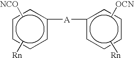
where A represents independently a single bond, ——C(CH3)(H)——, ——SO2——, ——O——, ——C(CF2)2——, ——CH2OCH2——, ——S——, ——C(═O)——. ——O——C(═O)——O——, ——S(═O)——, ——O——P(═O)——O——, ——O——P(═O)(═O)——O——, divalent alkylene radicals such as ——CH2—— and ——C(CH3)2——; divalent alkylene radicals interrupted by heteroatoms in the chain such as O, S, and N.

in which each a and b is independently 0, 1, 2, or 3, and at least one a is not 0; n is within the range of 0 to about 8, preferably 0 to 3; each R is independently selected from non-interfering alkyl, aryl, alkaryl, heteroatomic, heterocyclic, carbonyloxy, carboxy, and the like ring substituents, such as hydrogen, C1-6 alkyl, C1-6 allyl, C1-6 alkoxy, halogen, maleimide, propargyl ether, glycidyl ether, and the like; and A is a polyvalent linking moiety which can be, for example, aromatic, aliphatic, cycloaliphatic, polycyclic, and heteroatomic. Examples of linking moiety A include ——O——, ——SO2——, ——CO——, ——OCOO——, ——S——, ——C1-12——, dicyclopentadienyl, aralkyl, aryl, cycloaliphatic, and a direct bond.
Claims (5)
Priority Applications (2)
| Application Number | Priority Date | Filing Date | Title |
|---|---|---|---|
| US11/182,167 US7278207B2 (en) | 2001-01-16 | 2005-07-15 | Method of making an electronic package |
| US11/778,155 US20070278654A1 (en) | 2001-01-16 | 2007-07-16 | Method of making an electronic package |
Applications Claiming Priority (3)
| Application Number | Priority Date | Filing Date | Title |
|---|---|---|---|
| US09/761,124 US6486415B2 (en) | 2001-01-16 | 2001-01-16 | Compliant layer for encapsulated columns |
| US10/251,072 US6961995B2 (en) | 2001-01-16 | 2002-09-19 | Method of making an electronic package |
| US11/182,167 US7278207B2 (en) | 2001-01-16 | 2005-07-15 | Method of making an electronic package |
Related Parent Applications (1)
| Application Number | Title | Priority Date | Filing Date |
|---|---|---|---|
| US10/251,072 Continuation US6961995B2 (en) | 2001-01-16 | 2002-09-19 | Method of making an electronic package |
Related Child Applications (1)
| Application Number | Title | Priority Date | Filing Date |
|---|---|---|---|
| US11/778,155 Continuation US20070278654A1 (en) | 2001-01-16 | 2007-07-16 | Method of making an electronic package |
Publications (2)
| Publication Number | Publication Date |
|---|---|
| US20050250249A1 US20050250249A1 (en) | 2005-11-10 |
| US7278207B2 true US7278207B2 (en) | 2007-10-09 |
Family
ID=25061222
Family Applications (4)
| Application Number | Title | Priority Date | Filing Date |
|---|---|---|---|
| US09/761,124 Expired - Lifetime US6486415B2 (en) | 2001-01-16 | 2001-01-16 | Compliant layer for encapsulated columns |
| US10/251,072 Expired - Fee Related US6961995B2 (en) | 2001-01-16 | 2002-09-19 | Method of making an electronic package |
| US11/182,167 Expired - Fee Related US7278207B2 (en) | 2001-01-16 | 2005-07-15 | Method of making an electronic package |
| US11/778,155 Abandoned US20070278654A1 (en) | 2001-01-16 | 2007-07-16 | Method of making an electronic package |
Family Applications Before (2)
| Application Number | Title | Priority Date | Filing Date |
|---|---|---|---|
| US09/761,124 Expired - Lifetime US6486415B2 (en) | 2001-01-16 | 2001-01-16 | Compliant layer for encapsulated columns |
| US10/251,072 Expired - Fee Related US6961995B2 (en) | 2001-01-16 | 2002-09-19 | Method of making an electronic package |
Family Applications After (1)
| Application Number | Title | Priority Date | Filing Date |
|---|---|---|---|
| US11/778,155 Abandoned US20070278654A1 (en) | 2001-01-16 | 2007-07-16 | Method of making an electronic package |
Country Status (1)
| Country | Link |
|---|---|
| US (4) | US6486415B2 (en) |
Cited By (1)
| Publication number | Priority date | Publication date | Assignee | Title |
|---|---|---|---|---|
| US20080169140A1 (en) * | 2007-01-16 | 2008-07-17 | Charles Hampton Perry | Machine for augmentation, storage, and conservation of vehicle motive energy |
Families Citing this family (21)
| Publication number | Priority date | Publication date | Assignee | Title |
|---|---|---|---|---|
| US6889429B2 (en) * | 2001-03-26 | 2005-05-10 | Semiconductor Components Industries, L.L.C. | Method of making a lead-free integrated circuit package |
| JP2003174249A (en) * | 2001-12-06 | 2003-06-20 | Rohm Co Ltd | Circuit board and method for manufacturing the circuit board |
| US20040000428A1 (en) * | 2002-06-26 | 2004-01-01 | Mirng-Ji Lii | Socketless package to circuit board assemblies and methods of using same |
| US6870270B2 (en) * | 2002-12-28 | 2005-03-22 | Intel Corporation | Method and structure for interfacing electronic devices |
| US7226654B2 (en) * | 2003-07-29 | 2007-06-05 | Kyocera Corporation | Laminated wiring board and its mounting structure |
| US8084866B2 (en) * | 2003-12-10 | 2011-12-27 | Micron Technology, Inc. | Microelectronic devices and methods for filling vias in microelectronic devices |
| US7245022B2 (en) * | 2003-11-25 | 2007-07-17 | International Business Machines Corporation | Semiconductor module with improved interposer structure and method for forming the same |
| CN100531528C (en) * | 2004-05-27 | 2009-08-19 | 揖斐电株式会社 | Multilayer printed wiring board |
| JP2008198628A (en) * | 2005-05-11 | 2008-08-28 | Sharp Corp | Semiconductor device, manufacturing method thereof, and liquid crystal display |
| JP4862893B2 (en) * | 2006-06-02 | 2012-01-25 | 株式会社村田製作所 | Multilayer ceramic electronic component and manufacturing method thereof |
| KR100792352B1 (en) * | 2006-07-06 | 2008-01-08 | 삼성전기주식회사 | Bottom substrate of pop and manufacturing method thereof |
| US8829663B2 (en) * | 2007-07-02 | 2014-09-09 | Infineon Technologies Ag | Stackable semiconductor package with encapsulant and electrically conductive feed-through |
| JP5877673B2 (en) * | 2011-09-07 | 2016-03-08 | 新光電気工業株式会社 | Wiring substrate, manufacturing method thereof, and semiconductor package |
| US10050004B2 (en) * | 2015-11-20 | 2018-08-14 | Deca Technologies Inc. | Fully molded peripheral package on package device |
| NL2009757C2 (en) * | 2012-11-05 | 2014-05-08 | Micronit Microfluidics Bv | Method for forming an electrically conductive via in a substrate. |
| CN103102484B (en) * | 2013-01-22 | 2015-06-17 | 广东生益科技股份有限公司 | Crosslinkable polyphenyl ether resin, preparation method and use thereof |
| US9350062B2 (en) * | 2014-08-12 | 2016-05-24 | Anaren, Inc. | Stress relieved high power RF circuit |
| CN107923884B (en) * | 2015-08-25 | 2020-10-16 | 昭和电工株式会社 | Column for liquid chromatography and liquid chromatography apparatus provided with same |
| US11056453B2 (en) | 2019-06-18 | 2021-07-06 | Deca Technologies Usa, Inc. | Stackable fully molded semiconductor structure with vertical interconnects |
| US11056850B2 (en) | 2019-07-26 | 2021-07-06 | Eagle Technology, Llc | Systems and methods for providing a soldered interface on a printed circuit board having a blind feature |
| US11602800B2 (en) | 2019-10-10 | 2023-03-14 | Eagle Technology, Llc | Systems and methods for providing an interface on a printed circuit board using pin solder enhancement |
Citations (18)
| Publication number | Priority date | Publication date | Assignee | Title |
|---|---|---|---|---|
| US4713494A (en) * | 1985-04-12 | 1987-12-15 | Hitachi, Ltd. | Multilayer ceramic circuit board |
| JPS63307768A (en) | 1987-06-09 | 1988-12-15 | Hitachi Chem Co Ltd | Multilayer circuit board for loading semiconductor |
| US4937707A (en) | 1988-05-26 | 1990-06-26 | International Business Machines Corporation | Flexible carrier for an electronic device |
| US4954878A (en) | 1989-06-29 | 1990-09-04 | Digital Equipment Corp. | Method of packaging and powering integrated circuit chips and the chip assembly formed thereby |
| US5065227A (en) | 1990-06-04 | 1991-11-12 | International Business Machines Corporation | Integrated circuit packaging using flexible substrate |
| US5108785A (en) * | 1989-09-15 | 1992-04-28 | Microlithics Corporation | Via formation method for multilayer interconnect board |
| US5362656A (en) | 1992-12-02 | 1994-11-08 | Intel Corporation | Method of making an electronic assembly having a flexible circuit wrapped around a substrate |
| US5386341A (en) | 1993-11-01 | 1995-01-31 | Motorola, Inc. | Flexible substrate folded in a U-shape with a rigidizer plate located in the notch of the U-shape |
| US5517754A (en) | 1994-06-02 | 1996-05-21 | International Business Machines Corporation | Fabrication processes for monolithic electronic modules |
| US5530288A (en) | 1994-10-12 | 1996-06-25 | International Business Machines Corporation | Passive interposer including at least one passive electronic component |
| US5553769A (en) | 1992-11-12 | 1996-09-10 | International Business Machine Corporation | Interconnection of a carrier substrate and a semiconductor device |
| US5567654A (en) | 1994-09-28 | 1996-10-22 | International Business Machines Corporation | Method and workpiece for connecting a thin layer to a monolithic electronic module's surface and associated module packaging |
| US5781413A (en) | 1996-09-30 | 1998-07-14 | International Business Machines Corporation | Method and apparatus for directing the input/output connection of integrated circuit chip cube configurations |
| US5822856A (en) | 1996-06-28 | 1998-10-20 | International Business Machines Corporation | Manufacturing circuit board assemblies having filled vias |
| US5926029A (en) | 1997-05-27 | 1999-07-20 | International Business Machines Corporation | Ultra fine probe contacts |
| US5972734A (en) | 1997-09-17 | 1999-10-26 | Lsi Logic Corporation | Interposer for ball grid array (BGA) package |
| US5973391A (en) | 1997-12-11 | 1999-10-26 | Read-Rite Corporation | Interposer with embedded circuitry and method for using the same to package microelectronic units |
| US6081988A (en) * | 1998-04-30 | 2000-07-04 | Lockheed Martin Corp. | Fabrication of a circuit module with a coaxial transmission line |
Family Cites Families (19)
| Publication number | Priority date | Publication date | Assignee | Title |
|---|---|---|---|---|
| US3602635A (en) * | 1970-06-30 | 1971-08-31 | Ibm | Micro-circuit device |
| US4289719A (en) * | 1976-12-10 | 1981-09-15 | International Business Machines Corporation | Method of making a multi-layer ceramic substrate |
| CH670617A5 (en) * | 1986-04-25 | 1989-06-30 | Roag Ag | |
| US4788766A (en) * | 1987-05-20 | 1988-12-06 | Loral Corporation | Method of fabricating a multilayer circuit board assembly |
| US4894115A (en) * | 1989-02-14 | 1990-01-16 | General Electric Company | Laser beam scanning method for forming via holes in polymer materials |
| US5280414A (en) * | 1990-06-11 | 1994-01-18 | International Business Machines Corp. | Au-Sn transient liquid bonding in high performance laminates |
| US5168347A (en) * | 1991-03-26 | 1992-12-01 | International Business Machines Corporation | Integrated circuit chip package having signal input/output connections located at edges of the substrate |
| US5367764A (en) * | 1991-12-31 | 1994-11-29 | Tessera, Inc. | Method of making a multi-layer circuit assembly |
| JP2707903B2 (en) * | 1992-01-28 | 1998-02-04 | 日本電気株式会社 | Manufacturing method of multilayer printed wiring board |
| WO1994018701A1 (en) * | 1993-02-05 | 1994-08-18 | W.L. Gore & Associates, Inc. | Stress-resistant semiconductor chip-circuit board interconnect |
| US5306670A (en) * | 1993-02-09 | 1994-04-26 | Texas Instruments Incorporated | Multi-chip integrated circuit module and method for fabrication thereof |
| US5323520A (en) * | 1993-04-29 | 1994-06-28 | Fujitsu Limited | Process for fabricating a substrate with thin film capacitor |
| US5591941A (en) * | 1993-10-28 | 1997-01-07 | International Business Machines Corporation | Solder ball interconnected assembly |
| JP2716012B2 (en) * | 1995-08-10 | 1998-02-18 | 日本電気株式会社 | Semiconductor package and mounting method thereof |
| US5699613A (en) * | 1995-09-25 | 1997-12-23 | International Business Machines Corporation | Fine dimension stacked vias for a multiple layer circuit board structure |
| US5798563A (en) * | 1997-01-28 | 1998-08-25 | International Business Machines Corporation | Polytetrafluoroethylene thin film chip carrier |
| JP3152180B2 (en) * | 1997-10-03 | 2001-04-03 | 日本電気株式会社 | Semiconductor device and manufacturing method thereof |
| US6259039B1 (en) * | 1998-12-29 | 2001-07-10 | Intel Corporation | Surface mount connector with pins in vias |
| US6426545B1 (en) * | 2000-02-10 | 2002-07-30 | Epic Technologies, Inc. | Integrated circuit structures and methods employing a low modulus high elongation photodielectric |
-
2001
- 2001-01-16 US US09/761,124 patent/US6486415B2/en not_active Expired - Lifetime
-
2002
- 2002-09-19 US US10/251,072 patent/US6961995B2/en not_active Expired - Fee Related
-
2005
- 2005-07-15 US US11/182,167 patent/US7278207B2/en not_active Expired - Fee Related
-
2007
- 2007-07-16 US US11/778,155 patent/US20070278654A1/en not_active Abandoned
Patent Citations (21)
| Publication number | Priority date | Publication date | Assignee | Title |
|---|---|---|---|---|
| US4713494A (en) * | 1985-04-12 | 1987-12-15 | Hitachi, Ltd. | Multilayer ceramic circuit board |
| JPS63307768A (en) | 1987-06-09 | 1988-12-15 | Hitachi Chem Co Ltd | Multilayer circuit board for loading semiconductor |
| US4937707A (en) | 1988-05-26 | 1990-06-26 | International Business Machines Corporation | Flexible carrier for an electronic device |
| US4954878A (en) | 1989-06-29 | 1990-09-04 | Digital Equipment Corp. | Method of packaging and powering integrated circuit chips and the chip assembly formed thereby |
| US5108785A (en) * | 1989-09-15 | 1992-04-28 | Microlithics Corporation | Via formation method for multilayer interconnect board |
| US5065227A (en) | 1990-06-04 | 1991-11-12 | International Business Machines Corporation | Integrated circuit packaging using flexible substrate |
| US5553769A (en) | 1992-11-12 | 1996-09-10 | International Business Machine Corporation | Interconnection of a carrier substrate and a semiconductor device |
| US5362656A (en) | 1992-12-02 | 1994-11-08 | Intel Corporation | Method of making an electronic assembly having a flexible circuit wrapped around a substrate |
| US5386341A (en) | 1993-11-01 | 1995-01-31 | Motorola, Inc. | Flexible substrate folded in a U-shape with a rigidizer plate located in the notch of the U-shape |
| US5517754A (en) | 1994-06-02 | 1996-05-21 | International Business Machines Corporation | Fabrication processes for monolithic electronic modules |
| US5567654A (en) | 1994-09-28 | 1996-10-22 | International Business Machines Corporation | Method and workpiece for connecting a thin layer to a monolithic electronic module's surface and associated module packaging |
| US5786628A (en) | 1994-09-28 | 1998-07-28 | International Business Machines Corporation | Method and workpiece for connecting a thin layer to a monolithic electronic modules surface and associated module packaging |
| US5530288A (en) | 1994-10-12 | 1996-06-25 | International Business Machines Corporation | Passive interposer including at least one passive electronic component |
| US5770476A (en) | 1994-10-12 | 1998-06-23 | International Business Machines Corporation | Passive interposer including at least one passive electronic component |
| US6127025A (en) * | 1996-06-28 | 2000-10-03 | International Business Machines Corporation | Circuit board with wiring sealing filled holes |
| US5822856A (en) | 1996-06-28 | 1998-10-20 | International Business Machines Corporation | Manufacturing circuit board assemblies having filled vias |
| US5781413A (en) | 1996-09-30 | 1998-07-14 | International Business Machines Corporation | Method and apparatus for directing the input/output connection of integrated circuit chip cube configurations |
| US5926029A (en) | 1997-05-27 | 1999-07-20 | International Business Machines Corporation | Ultra fine probe contacts |
| US5972734A (en) | 1997-09-17 | 1999-10-26 | Lsi Logic Corporation | Interposer for ball grid array (BGA) package |
| US5973391A (en) | 1997-12-11 | 1999-10-26 | Read-Rite Corporation | Interposer with embedded circuitry and method for using the same to package microelectronic units |
| US6081988A (en) * | 1998-04-30 | 2000-07-04 | Lockheed Martin Corp. | Fabrication of a circuit module with a coaxial transmission line |
Non-Patent Citations (1)
| Title |
|---|
| IBM Technical Disclosure Bulletin, vol. 36, No. 7, Jul. 1993, pp. 137-138, "Interposer for Direct Chip Attach or Surface Mount Array Devices". |
Cited By (1)
| Publication number | Priority date | Publication date | Assignee | Title |
|---|---|---|---|---|
| US20080169140A1 (en) * | 2007-01-16 | 2008-07-17 | Charles Hampton Perry | Machine for augmentation, storage, and conservation of vehicle motive energy |
Also Published As
| Publication number | Publication date |
|---|---|
| US20030020150A1 (en) | 2003-01-30 |
| US6486415B2 (en) | 2002-11-26 |
| US20020092676A1 (en) | 2002-07-18 |
| US20050250249A1 (en) | 2005-11-10 |
| US20070278654A1 (en) | 2007-12-06 |
| US6961995B2 (en) | 2005-11-08 |
Similar Documents
| Publication | Publication Date | Title |
|---|---|---|
| US7278207B2 (en) | Method of making an electronic package | |
| US6516513B2 (en) | Method of making a CTE compensated chip interposer | |
| US5120678A (en) | Electrical component package comprising polymer-reinforced solder bump interconnection | |
| KR101037229B1 (en) | Semiconductor device and semiconductor device manufacturing method | |
| US6569711B1 (en) | Methods and apparatus for balancing differences in thermal expansion in electronic packaging | |
| US6639155B1 (en) | High performance packaging platform and method of making same | |
| US5292688A (en) | Solder interconnection structure on organic substrates and process for making | |
| US5656862A (en) | Solder interconnection structure | |
| US6191952B1 (en) | Compliant surface layer for flip-chip electronic packages and method for forming same | |
| US6335491B1 (en) | Interposer for semiconductor package assembly | |
| US6335571B1 (en) | Semiconductor flip-chip package and method for the fabrication thereof | |
| US6399426B1 (en) | Semiconductor flip-chip package and method for the fabrication thereof | |
| KR100598748B1 (en) | An electronic package having a thermal stretching layer | |
| US20050006789A1 (en) | Packaging assembly and method of assembling the same | |
| US6187610B1 (en) | Flexible thin film ball grid array containing solder mask | |
| US6986454B2 (en) | Electronic package having controlled height stand-off solder joint | |
| US7118940B1 (en) | Method of fabricating an electronic package having underfill standoff | |
| US8629556B2 (en) | Semiconductor device | |
| US7504718B2 (en) | Apparatus and methods for constructing balanced chip packages to reduce thermally induced mechanical strain | |
| KR101409048B1 (en) | Circuit board manufacturing method, semiconductor manufacturing apparatus, circuit board and semiconductor device | |
| US7759794B2 (en) | Semiconductor device | |
| US20050173152A1 (en) | Circuit board surface mount package | |
| US6407927B1 (en) | Method and structure to increase reliability of input/output connections in electrical devices | |
| KR100696050B1 (en) | Attachment of a stiff heat spreader for fabricating a cavity down plastic chip carrier | |
| JP2002280703A (en) | Substrate for mounting electronic parts and method of mounting electronic parts using it |
Legal Events
| Date | Code | Title | Description |
|---|---|---|---|
| FEPP | Fee payment procedure |
Free format text: PAYOR NUMBER ASSIGNED (ORIGINAL EVENT CODE: ASPN); ENTITY STATUS OF PATENT OWNER: LARGE ENTITY |
|
| REMI | Maintenance fee reminder mailed | ||
| LAPS | Lapse for failure to pay maintenance fees | ||
| STCH | Information on status: patent discontinuation |
Free format text: PATENT EXPIRED DUE TO NONPAYMENT OF MAINTENANCE FEES UNDER 37 CFR 1.362 |
|
| FP | Lapsed due to failure to pay maintenance fee |
Effective date: 20111009 |
|
| AS | Assignment |
Owner name: GLOBALFOUNDRIES U.S. 2 LLC, NEW YORK Free format text: ASSIGNMENT OF ASSIGNORS INTEREST;ASSIGNOR:INTERNATIONAL BUSINESS MACHINES CORPORATION;REEL/FRAME:036550/0001 Effective date: 20150629 |
|
| AS | Assignment |
Owner name: GLOBALFOUNDRIES INC., CAYMAN ISLANDS Free format text: ASSIGNMENT OF ASSIGNORS INTEREST;ASSIGNORS:GLOBALFOUNDRIES U.S. 2 LLC;GLOBALFOUNDRIES U.S. INC.;REEL/FRAME:036779/0001 Effective date: 20150910 |