US7279024B2 - High purity cobalt, method of manufacturing thereof, and high purity cobalt targets - Google Patents

High purity cobalt, method of manufacturing thereof, and high purity cobalt targets Download PDF

Info

Publication number
US7279024B2
US7279024B2 US10/803,506 US80350604A US7279024B2 US 7279024 B2 US7279024 B2 US 7279024B2 US 80350604 A US80350604 A US 80350604A US 7279024 B2 US7279024 B2 US 7279024B2
Authority
US
United States
Prior art keywords
cobalt
aqueous solution
cobalt chloride
high purity
copper ions
Prior art date
Legal status (The legal status is an assumption and is not a legal conclusion. Google has not performed a legal analysis and makes no representation as to the accuracy of the status listed.)
Expired - Lifetime, expires
Application number
US10/803,506
Other versions
US20070180953A1 (en
Inventor
Masahito Uchikoshi
Norio Yokoyama
Tamas Kekesi
Minoru Isshiki
Current Assignee (The listed assignees may be inaccurate. Google has not performed a legal analysis and makes no representation or warranty as to the accuracy of the list.)
Sony Corp
Original Assignee
Sony Corp
Priority date (The priority date is an assumption and is not a legal conclusion. Google has not performed a legal analysis and makes no representation as to the accuracy of the date listed.)
Filing date
Publication date
Application filed by Sony Corp filed Critical Sony Corp
Priority to US10/803,506 priority Critical patent/US7279024B2/en
Publication of US20070180953A1 publication Critical patent/US20070180953A1/en
Application granted granted Critical
Publication of US7279024B2 publication Critical patent/US7279024B2/en
Adjusted expiration legal-status Critical
Expired - Lifetime legal-status Critical Current

Links

Images

Classifications

    • CCHEMISTRY; METALLURGY
    • C22METALLURGY; FERROUS OR NON-FERROUS ALLOYS; TREATMENT OF ALLOYS OR NON-FERROUS METALS
    • C22BPRODUCTION AND REFINING OF METALS; PRETREATMENT OF RAW MATERIALS
    • C22B23/00Obtaining nickel or cobalt
    • C22B23/04Obtaining nickel or cobalt by wet processes
    • C22B23/0407Leaching processes
    • C22B23/0415Leaching processes with acids or salt solutions except ammonium salts solutions
    • C22B23/0423Halogenated acids or salts thereof
    • CCHEMISTRY; METALLURGY
    • C22METALLURGY; FERROUS OR NON-FERROUS ALLOYS; TREATMENT OF ALLOYS OR NON-FERROUS METALS
    • C22BPRODUCTION AND REFINING OF METALS; PRETREATMENT OF RAW MATERIALS
    • C22B23/00Obtaining nickel or cobalt
    • CCHEMISTRY; METALLURGY
    • C22METALLURGY; FERROUS OR NON-FERROUS ALLOYS; TREATMENT OF ALLOYS OR NON-FERROUS METALS
    • C22BPRODUCTION AND REFINING OF METALS; PRETREATMENT OF RAW MATERIALS
    • C22B23/00Obtaining nickel or cobalt
    • C22B23/04Obtaining nickel or cobalt by wet processes
    • C22B23/0453Treatment or purification of solutions, e.g. obtained by leaching
    • C22B23/0461Treatment or purification of solutions, e.g. obtained by leaching by chemical methods
    • CCHEMISTRY; METALLURGY
    • C22METALLURGY; FERROUS OR NON-FERROUS ALLOYS; TREATMENT OF ALLOYS OR NON-FERROUS METALS
    • C22BPRODUCTION AND REFINING OF METALS; PRETREATMENT OF RAW MATERIALS
    • C22B3/00Extraction of metal compounds from ores or concentrates by wet processes
    • C22B3/20Treatment or purification of solutions, e.g. obtained by leaching
    • C22B3/42Treatment or purification of solutions, e.g. obtained by leaching by ion-exchange extraction
    • YGENERAL TAGGING OF NEW TECHNOLOGICAL DEVELOPMENTS; GENERAL TAGGING OF CROSS-SECTIONAL TECHNOLOGIES SPANNING OVER SEVERAL SECTIONS OF THE IPC; TECHNICAL SUBJECTS COVERED BY FORMER USPC CROSS-REFERENCE ART COLLECTIONS [XRACs] AND DIGESTS
    • Y02TECHNOLOGIES OR APPLICATIONS FOR MITIGATION OR ADAPTATION AGAINST CLIMATE CHANGE
    • Y02PCLIMATE CHANGE MITIGATION TECHNOLOGIES IN THE PRODUCTION OR PROCESSING OF GOODS
    • Y02P10/00Technologies related to metal processing
    • Y02P10/20Recycling

Definitions

  • the present invention relates to high purity cobalt in which a content of impurities such as copper is reduced, a method of manufacturing thereof, and high purity cobalt targets.
  • VLSI very large scale integrated circuit
  • ULSI ultra LSI
  • Si silicon
  • Co cobalt
  • the accompanying injurious impurities in the cobalt may result in malfunction or deterioration of the semiconductor device, which is undesirable.
  • copper (Cu) may cause a short circuit because of high diffusion rate inside silicon, and radioactive elements such as uranium (U) and thorium (Th) will cause incorrect operations, and alkaline metals and alkaline-earth metals may cause degradation of the device properties.
  • transition metals such as nickel (Ni) iron (Fe), and chromium (Cr)
  • gas elements such as oxygen (O), nitrogen (N), and sulfur (S). Therefore, in order to use cobalt for a semiconductor device, it is necessary to remove these impurities from the crude cobal
  • the present invention has been achieved in view of the above problems. It is an object of the invention to provide high purity cobalt and high purity cobalt targets in which contents of impurities such as copper are reduced.
  • the invention provides high purity cobalt with 99.99 mass % or more in purity wherein a copper impurity content is 50 mass ppb or less.
  • the invention provides high purity cobalt wherein a residual resistivity ratio thereof is 150 or more, and a copper impurity content is 50 mass ppb or less.
  • a method of manufacturing high purity cobalt according to the invention includes the steps of converting divalent copper ions as impurities contained in an aqueous solution of cobalt chloride to monovalent copper ions; adjusting a concentration of hydrochloric acid in a range of 0.1 kmol/m 3 to 3 kmol/m 3 ; and separating the monovalent copper ions from the aqueous solution of cobalt chloride by using anion exchange resins.
  • a method of manufacturing high purity cobalt according to the invention includes the step of heating cobalt chloride or hydrates thereof from 623K to less than 873K in a hydrogen atmosphere in order to obtain cobalt.
  • the invention provides high purity cobalt targets with 99.99 mass % or more in purity wherein a copper impurity content is 50 mass ppb or less.
  • the invention provides high purity cobalt targets wherein a residual resistivity ratio is 150 or more, and a copper impurity content is 50 mass ppb or less.
  • concentration of copper is reduced to 50 mass ppb or less to achieve high purification.
  • the method of manufacturing the high purity cobalt according to the invention includes the steps of converting divalent copper ions to monovalent copper ions, and adjusting a concentration of hydrochloric acid. These steps allow copper to be absorbed on anion exchange resins, and cobalt not to be absorbed thereon. Thus the copper can be separated easily and surely from the aqueous solution of cobalt chloride.
  • Another method of manufacturing high purity cobalt according to the invention includes the step of heating cobalt chloride or hydrates thereof from 623K to less than 873K in a hydrogen atmosphere in order to obtain high purity cobalt easily and surely.
  • FIG. 1 is a flow chart illustrating a manufacturing process of high purity cobalt and high purity cobalt targets according to one embodiment of the invention.
  • FIG. 2 is a flow chart illustrating the manufacturing process following FIG. 1 .
  • FIG. 3 is a diagram explaining one step of the manufacturing process shown in FIG. 1 .
  • FIG. 4 is a diagram explaining another step of the manufacturing processes shown in FIG. 1 .
  • FIG. 5 is a graph illustrating changes of the concentrations of metal ions in the liquid eluted from the column filled up with the anion exchange resins.
  • FIG. 6 is a diagram explaining one step of the manufacturing processes shown in FIG. 2 .
  • FIG. 7 is a graph illustrating the relationship between the heating temperature of cobalt chloride and the reaction rate.
  • FIG. 8 is a photograph of the cobalt particles obtained in the example of the invention.
  • high purity cobalt and high purity cobalt targets have 99.99 mass % or more in purity, or the residual resistivity ratios thereof are 150 or more and copper impurity contents thereof are 50 mass ppb or less.
  • purity means values obtained by one minus all concentrations of impurities possible to be determined by using present analysis apparatus and methods (Minoru Isshiki, Koji Mimura, Bulletin of the Japan Institute of Metals, 31 (1992), 880-887).
  • the values can be obtained by one minus the concentrations of impurities of 70 or more elements determined by Glow Discharge Mass Spectroscopy.
  • concentrations of gas elements such as oxygen, nitrogen, and hydrogen, if required, can be determined by appropriate methods such as a non-dispersive infrared absorption method, a thermal conductivity method, and a heat conduction measurement of such gas elements separated with a column after being fused in an inert gas.
  • Residual resistivity ratios provide one index showing purities of high purified metals and as shown in the formula I, the residual resistivity ratio is the ratio of resistivity at 298 K to resistivity at 4.2 K.
  • the formula II shows a relationship between resistivity and resistance (electric resistance). Therefore, the formula I expressing the residual resistivity ratio can be transformed into the formula III, and if volume changes by temperature are negligible, the formula I can be approximated by the ratio of the resistance at 298 K to the resistance at 4.2 K.
  • cobalt is a ferromagnetic metal and factors such as, geomagnetism, demagnetization conditions, and magnetic fields by measurement currents can affect the resistance measurements.
  • RRR R 298 ⁇ K ⁇ S 298 ⁇ K L 298 ⁇ K R 4.2 ⁇ K ⁇ S 4.2 ⁇ K L 4.2 ⁇ K ⁇ R 298 ⁇ K R 4.2 ⁇ K ( III )
  • R 298 K , S 298 K , and L 298 K respectively, resistance, cross-section area, length at 298 K
  • R 4.2 K , S 4.2 K , and L 4.2 K respectively resistance, cross-section area, length at 4.2 K
  • the high purity cobalt and the high purity cobalt targets may be used as materials of devices, for example, semiconductor devices, magnetic recording mediums, magnetic recording heads, and devices with environmental semiconductors.
  • the term “environmental semiconductor” used herein means a semiconductor substance that exists abundantly on the earth and consists of an eco-friendly material, for example, iron silicide (FeSi 2 ) and calcium silicide (Ca 2 Si) (See the website of Society of Kankyo Semiconductors (http ://kan.engjm.saitama-u.ac.jp/SKS/index2.html)).
  • Such high purity cobalt and such high purity cobalt targets can be manufactured as follows.
  • FIGS. 1 and 2 show the manufacturing process of the high purity cobalt according to the embodiment.
  • the cobalt containing impurities such as copper is dissolved in a hydrochloric acid solution in order to prepare an aqueous solution of cobalt chloride (CoCl 2 ) (Step S 101 ).
  • the concentration of the hydrochloric acid is adjusted in a range of 0.1 kmol/m 3 to 3 kmol/m 3 .
  • the aqueous solution of cobalt chloride M is poured into a container 12 with a metal 11 such as cobalt. Then, the aqueous solution of cobalt chloride M is sufficiently contacted with the metal 11 by agitating with a device such as a stirrer 14 , while injecting an inert gas 13 such as nitrogen gas (N 2 ) or argon gas (Ar) into the aqueous solution M (Step S 102 ).
  • an inert gas 13 such as nitrogen gas (N 2 ) or argon gas (Ar) into the aqueous solution M
  • N 2 nitrogen gas
  • Ar argon gas
  • injecting the inert gas 13 into the aqueous solution of cobalt chloride M intends to remove oxygen dissolved in the aqueous solution of cobalt chloride M, in order to carry out the reaction.
  • the inert gas 13 may be injected with agitating the aqueous solution of cobalt chloride M containing the metal 11 , or before the metal 11 is added into the aqueous solution of cobalt chloride M.
  • the metal 11 has large surface area such as powder, which can contact more effectively with the aqueous solution of cobalt chloride M and react sufficiently with the copper.
  • Substances other than cobalt can also be used for the metal 11 . It is preferred to use cobalt for the metal 11 in order to avoid other impurities from contaminating the aqueous solution of cobalt chloride M as much as possible.
  • the divalent copper ions in the aqueous solution of cobalt chloride M may be converted to the monovalent copper ions by contacting with the metal 11 after adjusting the concentration of hydrochloric acid in the aqueous solution of cobalt chloride M as described above, or before adjusting the concentration of hydrochloric acid in the aqueous solution of cobalt chloride.
  • a column 22 is filled up with anion exchange resins 21 , the aqueous solution of cobalt chloride M is fed into the column 22 from a storage tank 23 , and is contacted with the anion exchange resins 21 sufficiently (Step S 103 ).
  • the flow rate of the aqueous solution of cobalt chloride M is determined effectively to contact the aqueous solution of cobalt chloride M with the anion exchange resins 21 sufficiently, and is preferably 1 bed volume(s)/hour.
  • the monovalent copper ions will be absorbed on the anion exchange resins 21 , and the cobalt will be eluted from the column 22 without being completely absorbed on the anion exchange resins 21 .
  • FIG. 5 shows changes of the concentrations of metal ions in the effluent (elution curve).
  • the abscissa represents the effluent volumes and the ordinate represents the concentrations standardized by the maximum concentrations of the metal ions.
  • Elements separated like zinc include, for example, technetium (Te), ruthenium (Ru), palladium (Pd), silver (Ag), cadmium (Cd), indium (In), tin (Sn), rhenium (Re), osmium (Os), iridium (Ir), platinum (Pt), gold (Au), mercury (Hg), thallium (Tl), lead (Pb), bismuth (Bi), and polonium (Po). That is, when at least one of such impurities is contained in the aqueous solution of cobalt chloride M, the impurities can be separated as well as the copper.
  • the concentration of hydrochloric acid of the aqueous solution of cobalt chloride M is adjusted in the range of 7 kmol/m 3 to 11 kmol/m 3 and, as shown in FIG. 4 , the aqueous solution of cobalt chloride M is sufficiently contacted on the anion exchange resins 21 (Step S 104 ).
  • the cobalt will be absorbed on the anion exchange resins 21 , and the impurities such as titanium, chromium, manganese, nickel, aluminum, alkaline metals, and alkaline-earth metals will not be absorbed on the anion exchange resins 21 and will be separated from the cobalt.
  • impurities selected from the group consisting of iron, zinc, molybdenum (Mo), technetium, ruthenium, palladium, silver, cadmium, indium, tin, tungsten (W), rhenium, osmium, iridium, platinum, gold, mercury, thallium, lead, bismuth, and polonium is contained in the aqueous solution of cobalt chloride M, such impurities can be absorbed on the anion exchange resins 21 as well as the cobalt in the Step S 104 .
  • Step S 105 after absorbing the cobalt on the anion exchange resins 21 , 2.5 kmol/m 3 to 5 kmol/m 3 of hydrochloric acid solution is passed through the column 22 to elute the cobalt from the anion exchange resins 21 and separate the cobalt from the impurities absorbed on the anion exchange resins 21 such as iron, zinc, molybdenum, technetium, ruthenium, palladium, silver, cadmium, indium, tin, tungsten, rhenium, osmium, iridium, platinum, gold, mercury, thallium, lead, bismuth, and polonium (Step S 105 ).
  • the impurities absorbed on the anion exchange resins 21 such as iron, zinc, molybdenum, technetium, ruthenium, palladium, silver, cadmium, indium, tin, tungsten, rhenium, osmium, iridium, platinum, gold,
  • iron, molybdenum, and tungsten will be mainly separated from the cobalt in the Step S 105 , because zinc, technetium, ruthenium, palladium, silver, cadmium, indium, tin, rhenium, osmium, iridium, platinum, gold, mercury, thallium, lead, bismuth, and polonium have already been separated from the aqueous solution of cobalt chloride M with the copper in the Step S 103 .
  • the obtained aqueous solution of cobalt chloride M is evaporated to dryness to obtain cobalt chloride or hydrates thereof (Step S 106 ). Then, the obtained cobalt chloride or hydrates thereof are heated to 623 K to less than 873 K (350° C. to less than 600° C.) in a hydrogen atmosphere by using an equipment as shown in FIG. 6 (Step S 107 ). Thus, the cobalt chloride or hydrates thereof will react as shown in the chemical formula 2 to obtain cobalt.
  • the equipment shown in FIG. 6 includes a heating furnace 31 and a reaction pipe 32 located within the heating furnace 31 .
  • Hydrogen gas 33 is supplied through a first end part of the reaction pipe 32 , and hydrogen chloride gas generated by the reaction is discharged through a second end part.
  • the discharged gas is send to a processing part 34 .
  • CoCl 2 (solid)+H 2 (gas) Co(solid)+2HCl(gas) (2)
  • FIG. 7 shows the relationship between the heating temperature and the reaction rate (reduction rate).
  • the abscissas represent times and the ordinates represent rates of reduction.
  • the rates of reduction are obtained by concentration changes of the collected hydrogen chloride based on the theory that 2 moles of hydrogen chloride are generated by reduction of 1 mole of cobalt as shown in the chemical formula 2.
  • FIG. 7 also shows that the cobalt can sufficiently be reduced at 623 K to less than 873 K.
  • the obtained cobalt is molten with plasma arc using a plasma generation gas containing active hydrogen, in order to remove at least one of impurities selected from the group consisting of oxygen, nitrogen, carbon (C), sulfur, halogen, alkaline metals, and alkaline-earth metals (Step S 108 ).
  • a plasma generation gas containing active hydrogen in order to remove at least one of impurities selected from the group consisting of oxygen, nitrogen, carbon (C), sulfur, halogen, alkaline metals, and alkaline-earth metals.
  • the high purity cobalt and the high purity cobalt targets according to the embodiment may be obtained by the following procedure for separating impurities from the aqueous solution of cobalt chloride M.
  • Step S 102 the concentration of hydrochloric acid of the aqueous solution of cobalt chloride M is adjusted from 7 kmol/m 3 to 11 kmol/m 3 , and the cobalt is contacted with the anion exchange resins 21 to absorb the cobalt thereon and separate the cobalt from the impurities such as titanium (Step S 104 ).
  • Step S 105 the concentration of hydrochloric acid of the aqueous solution of cobalt chloride M is adjusted from 0.1 kmol/m 3 to 3 kmol/m 3 (Step S 101 ), and the aqueous solution of cobalt chloride M is contacted with the anion exchange resins 21 to absorb the copper and separate the copper from the aqueous solution of cobalt chloride M (Step S 103 ).
  • Step S 102 after converting the divalent copper ions to the monovalent copper ions (Step S 102 ), the following procedure may be performed, that is, adjusting the concentration of hydrochloric acid of the aqueous solution of cobalt chloride M, contacting the aqueous solution of cobalt chloride M with the anion exchange resins 21 to absorb the cobalt thereon to separate the impurities such as titanium (Step S 104 ), eluting the cobalt from the column filled up with the anion exchange resins 21 with a 0.1 kmol/m 3 to 3 kmol/m 3 of hydrochloric acid solution to separate the cobalt with the impurities such as copper absorbed on the anion exchange resins 21 , adjusting the concentration of hydrochloric acid of the aqueous solution of cobalt chloride M from 2.5 kmol/m 3 to 5 kmol/m 3 , contacting the aqueous solution of cobalt chloride M with the anion exchange resins 21 to absorb the impur
  • the concentration of the hydrochloric acid solution for eluting the cobalt absorbed on the anion exchange resins 21 may be adjust from 2.5 kmol/m 3 to 3 kmol/m 3 to separate the impurities such as iron, molybdenum, and tungsten as well as the copper.
  • the contents of copper may be reduced to 50 mass ppb or less. Therefore, the high purity cobalt or the cobalt targets according to the invention may not be responsible for short circuit of devices such as semiconductor devices and can be applied to the semiconductor devices for the enhancement of properties. Moreover, the high purity cobalt and the high purity cobalt targets can use for devices such as magnetic recording mediums, magnetic recording heads, devices using environmental semiconductor, and the like for the enhancement of properties.
  • the divalent copper ions is converted to the monovalent copper ions and the concentrations of the hydrochloric acid are adjusted from 0.1 kmol/m 3 to 3 kmol/m 3 . Therefore, the copper may be absorbed on the anion exchange resins and be separated from the aqueous solution of cobalt chloride easily and the high purity cobalt and the high purity cobalt targets with low concentrations of copper can be obtained easily and surely.
  • cobalt chloride or hydrates thereof are heated to the temperature of 623 K to less than 873K in a hydrogen atmosphere, and the cobalt can be easily and surely obtained at low temperature. Therefore, the embodiment provides a lower processing cost and compact manufacturing equiptments.
  • FIGS. 1 to 6 The invention will be further described in detail by reference to FIGS. 1 to 6 .
  • the same reference numbers and signs will be used for equivalents of the substances in the above embodiments.
  • scrap cobalt used as a material was dissolved into 1.5 kmol/m 3 of hydrochloric acid solution until the concentration of the cobalt reached 0.34 kmol/m 3 (20 g/dm 3 ) (Step S 101 ).
  • powdered cobalt 11 was added to the aqueous solution of cobalt chloride M, and inert gas was injected into the solution M with agitating, as shown in FIG. 3 , to convert divalent copper ions to monovalent copper ions (Step S 102 ).
  • the aqueous solution of cobalt chloride M was contacted with anion exchange resins 21 to absorb the copper and separate the copper from the aqueous solution of cobalt chloride M (Step S 103 ).
  • the concentration of hydrochloric acid of the aqueous solution of cobalt chloride M was adjusted to 9 kmol/m 3 , and the aqueous solution of cobalt chloride M was contacted with the anion exchange resins 21 to absorb the cobalt and separate impurities such as titanium (Step S 104 ). Then, the cobalt was eluted from the column filled up with the anion exchange resins 21 with 4 kmol/m 3 of hydrochloric acid solution to separate impurities such as molybdenum (Step S 105 ).
  • Step S 106 After eluting the cobalt from the column filled up with the anion exchange resins 21 , the obtained aqueous solution of cobalt chloride M was evaporated to dryness to obtain cobalt chloride or hydrates thereof (Step S 106 ). And, as shown in FIG. 6 , the obtained cobalt chloride or hydrates thereof were heated to 743 K in a hydrogen atmosphere to obtain cobalt (Step S 107 ).
  • FIG. 8 shows a photograph of cobalt particles obtained in the Step S 107 . The cobalt was sponge-like rather than powdered as shown in FIG. 8 .
  • the cobalt obtained in the Step S 107 was molten with plasma arc containing active hydrogen to remove impurities such as oxygen (Step S 108 ) to obtain high purity cobalt.
  • the heating temperature of cobalt chloride or hydrates thereof in a hydrogen atmosphere for generating cobalt may be 623 K to less than 873K as described in the above embodiments and examples, or may be 873K or more.
  • impurities other than copper may be removed by the methods as described in the above embodiments and example, or by other conventional methods.
  • the method of generating cobalt by heating cobalt chloride or hydrates thereof from 623 K to less than 873K in a hydrogen atmosphere is applicable to other methods of separating the impurities from the aqueous solution of cobalt chloride as well as the methods as described in the above embodiments and examples.
  • the contents of copper that causes influences such as a short circuit may be reduced to 50 mass ppb or less. Therefore, the high purity cobalt or the high purity cobalt targets according to the invention applied to semiconductor devices may not be responsible for short circuit of semiconductor devices and can provide the enhancement of properties of the semiconductor devices. Moreover, the high purity cobalt and the high purity cobalt targets can be used for devices such as magnetic recording mediums, magnetic recording heads, devices using environmental semiconductor and the like for the enhancement of properties.
  • the divalent copper ions are converted to the monovalent copper ions and the concentration of the hydrochloric acid is adjusted from 0.1 kmol/m 3 to 3 kmol/m 3 . Therefore, the copper may be absorbed on the anion exchange resins and be separated from the aqueous solution of cobalt chloride easily.
  • the high purity cobalt and the high purity cobalt targets with low concentration of copper can be obtained easily and surely.
  • cobalt chloride or hydrates thereof are heated to the temperature of 623 K to less than 873K in hydrogen atmosphere, and the cobalt can be easily and surely obtained at low temperature. Therefore, the invention provides a lower processing cost and compact manufacturing equiptments.

Abstract

High purity cobalt with a very few content of impurities such as copper, a method of manufacturing thereof, and high purity cobalt targets are provided. The cobalt containing impurities such as copper is dissolved in a hydrochloric acid solution, and the concentration of the hydrochloric acid of the aqueous solution of cobalt chloride is adjusted to 0.1 kmol/m3 to 3 kmol/m3. Then, cobalt is added in the aqueous solution of cobalt chloride, and an inert gas is injected into the solution with agitating, in order to convert the divalent copper ions contained in the aqueous solution of cobalt chloride to monovalent copper ions. Then, the aqueous solution of cobalt chloride is fed into a column filled up with the anion exchange resins. Cobalt is not absorbed on the anion exchange resins although the monovalent copper ions are absorbed on the anion exchange resins. Therefore, copper can be separated from the aqueous solution of cobalt chloride. And then, the aqueous solution of cobalt chloride is evaporated to dryness and heated to 623 K to 873 K in a hydrogen atmosphere to generate cobalt.

Description

RELATED APPLICATION DATA
The present application claims priority to Japanese Application No. P2000-338288 filed Sep. 29, 2000, and is a divisional of U.S. Application Ser. No. 09/966,861, filed Sep. 28, 2001, now U.S. Pat. No. 6,740,290, both of which are incorporated herein by reference to the extent permitted by law.
BACKGROUND OF THE INVENTION
1. Field of the Invention
The present invention relates to high purity cobalt in which a content of impurities such as copper is reduced, a method of manufacturing thereof, and high purity cobalt targets.
2. Description of the Related Art
Semiconductor devices such as VLSI (very large scale integrated circuit) and ULSI (ultra LSI), have a structure where various thin metal films are deposited on, for example, a silicon (Si) wafer. Although the idea of using cobalt (Co) as a wiring material has been considered in recent years, the accompanying injurious impurities in the cobalt may result in malfunction or deterioration of the semiconductor device, which is undesirable. For example, copper (Cu) may cause a short circuit because of high diffusion rate inside silicon, and radioactive elements such as uranium (U) and thorium (Th) will cause incorrect operations, and alkaline metals and alkaline-earth metals may cause degradation of the device properties.
While levels in purity of the crude cobalt traded globally and presently are about 98% to 99.8%, such crude cobalt contains various impurities, for example, transition metals such as nickel (Ni) iron (Fe), and chromium (Cr), gas elements such as oxygen (O), nitrogen (N), and sulfur (S). Therefore, in order to use cobalt for a semiconductor device, it is necessary to remove these impurities from the crude cobalt and achieve higher purification. Moreover, cobalt appears favorable as material of devices such as magnetic recording mediums or magnetic recording heads, as well as semiconductor devices, because of bearing properties typical of ferromagnetic metals. A higher purification of cobalt is indispensable to the use of cobalt as material of these devices.
Various methods of removing impurities from crude cobalt, for example, wet processing such as solvent extraction, ion exchange, and electrolytic refining for separation of metallic elements, and dryness hydrogen gas (H2) processing for removal of gas elements such as oxygen and nitrogen, and floating zone melting refining method, have been studied.
SUMMARY OF THE INVENTION
However, there is a problem with the solvent extraction. It is difficult to control extraction and reverse extraction and to refine cobalt surely in industrial processes. And, although nearly all of metal impurities can be separated by the ion exchange, copper contents before and after refining by the ion exchange may not change, that is, it is difficult to remove copper, which is a problem with the ion exchange. In addition, there are problems with the electrolytic refining that pH control of electrolytic solutions is required, and it is difficult to remove nickel and copper. And, although the floating zone melting refining method is intended to further raise the purity level of metals purified to some extent, it is reported that the floating zone melting refining method has very few effects on purification of cobalt (V. G. Glebovsky, et al. Materials Letters, 36 (1998), pp. 308-314). Therefore, a need exists for methods of purifying cobalt surely, easily, and highly, and particularly for the development of methods of removing copper.
The present invention has been achieved in view of the above problems. It is an object of the invention to provide high purity cobalt and high purity cobalt targets in which contents of impurities such as copper are reduced.
It is another object of the invention to provide a method of easily and surely manufacturing high purity cobalt.
The invention provides high purity cobalt with 99.99 mass % or more in purity wherein a copper impurity content is 50 mass ppb or less.
In another aspect, the invention provides high purity cobalt wherein a residual resistivity ratio thereof is 150 or more, and a copper impurity content is 50 mass ppb or less.
A method of manufacturing high purity cobalt according to the invention includes the steps of converting divalent copper ions as impurities contained in an aqueous solution of cobalt chloride to monovalent copper ions; adjusting a concentration of hydrochloric acid in a range of 0.1 kmol/m3 to 3 kmol/m3; and separating the monovalent copper ions from the aqueous solution of cobalt chloride by using anion exchange resins.
In another aspect, a method of manufacturing high purity cobalt according to the invention includes the step of heating cobalt chloride or hydrates thereof from 623K to less than 873K in a hydrogen atmosphere in order to obtain cobalt.
The invention provides high purity cobalt targets with 99.99 mass % or more in purity wherein a copper impurity content is 50 mass ppb or less.
In another aspect, the invention provides high purity cobalt targets wherein a residual resistivity ratio is 150 or more, and a copper impurity content is 50 mass ppb or less.
In the high purity cobalt and the high purity cobalt targets according to the invention, concentration of copper is reduced to 50 mass ppb or less to achieve high purification.
The method of manufacturing the high purity cobalt according to the invention includes the steps of converting divalent copper ions to monovalent copper ions, and adjusting a concentration of hydrochloric acid. These steps allow copper to be absorbed on anion exchange resins, and cobalt not to be absorbed thereon. Thus the copper can be separated easily and surely from the aqueous solution of cobalt chloride.
Another method of manufacturing high purity cobalt according to the invention includes the step of heating cobalt chloride or hydrates thereof from 623K to less than 873K in a hydrogen atmosphere in order to obtain high purity cobalt easily and surely.
Other and further objects, features and advantages of the invention will appear more fully from the following description.
BRIEF DESCRIPTION OF THE DRAWINGS
FIG. 1 is a flow chart illustrating a manufacturing process of high purity cobalt and high purity cobalt targets according to one embodiment of the invention.
FIG. 2 is a flow chart illustrating the manufacturing process following FIG. 1.
FIG. 3 is a diagram explaining one step of the manufacturing process shown in FIG. 1.
FIG. 4 is a diagram explaining another step of the manufacturing processes shown in FIG. 1.
FIG. 5 is a graph illustrating changes of the concentrations of metal ions in the liquid eluted from the column filled up with the anion exchange resins.
FIG. 6 is a diagram explaining one step of the manufacturing processes shown in FIG. 2.
FIG. 7 is a graph illustrating the relationship between the heating temperature of cobalt chloride and the reaction rate.
FIG. 8 is a photograph of the cobalt particles obtained in the example of the invention.
DETAILED DESCRIPTION OF THE PREFERRED EMBODIMENTS
An embodiment of the present invention will be described in detail below with reference to the accompanying drawings.
In accordance with one embodiment of the invention, high purity cobalt and high purity cobalt targets have 99.99 mass % or more in purity, or the residual resistivity ratios thereof are 150 or more and copper impurity contents thereof are 50 mass ppb or less.
The term “purity” (namely, chemical purity) used herein means values obtained by one minus all concentrations of impurities possible to be determined by using present analysis apparatus and methods (Minoru Isshiki, Koji Mimura, Bulletin of the Japan Institute of Metals, 31 (1992), 880-887). For example, the values can be obtained by one minus the concentrations of impurities of 70 or more elements determined by Glow Discharge Mass Spectroscopy. The concentrations of gas elements such as oxygen, nitrogen, and hydrogen, if required, can be determined by appropriate methods such as a non-dispersive infrared absorption method, a thermal conductivity method, and a heat conduction measurement of such gas elements separated with a column after being fused in an inert gas.
Residual resistivity ratios provide one index showing purities of high purified metals and as shown in the formula I, the residual resistivity ratio is the ratio of resistivity at 298 K to resistivity at 4.2 K. The formula II shows a relationship between resistivity and resistance (electric resistance). Therefore, the formula I expressing the residual resistivity ratio can be transformed into the formula III, and if volume changes by temperature are negligible, the formula I can be approximated by the ratio of the resistance at 298 K to the resistance at 4.2 K. It should be noted that cobalt is a ferromagnetic metal and factors such as, geomagnetism, demagnetization conditions, and magnetic fields by measurement currents can affect the resistance measurements. Thus, it is necessary to apply vertical magnetic field which is preferably about 60 kA/m in measuring the resistance in order to suppress these influences (Seiichi Takagi, Materia Japan, 33 (1994), 6-10).
RRR=ρ 298 K4.2K  (I)
RRR; residual resistivity ratio
ρ298 K; resistivity at 298 K (Ωm)
ρ4.2 K; resistivity at 4.2 K (Ωm)
ρ=(S/L)  (II)
ρ; resistivity (Ωm)
R; resistance (Ω)
S; cross-section area perpendicular to the direction of current (m2)
L; length (m)
RRR = R 298 K × S 298 K L 298 K R 4.2 K × S 4.2 K L 4.2 K R 298 K R 4.2 K ( III )
RRR; residual resistivity ratio
R298 K, S298 K, and L298 K; respectively, resistance, cross-section area, length at 298 K
R4.2 K, S4.2 K, and L4.2 K; respectively resistance, cross-section area, length at 4.2 K
The high purity cobalt and the high purity cobalt targets may be used as materials of devices, for example, semiconductor devices, magnetic recording mediums, magnetic recording heads, and devices with environmental semiconductors. The term “environmental semiconductor” used herein means a semiconductor substance that exists abundantly on the earth and consists of an eco-friendly material, for example, iron silicide (FeSi2) and calcium silicide (Ca2Si) (See the website of Society of Kankyo Semiconductors (http ://kan.engjm.saitama-u.ac.jp/SKS/index2.html)).
Such high purity cobalt and such high purity cobalt targets can be manufactured as follows.
FIGS. 1 and 2 show the manufacturing process of the high purity cobalt according to the embodiment. First, the cobalt containing impurities such as copper is dissolved in a hydrochloric acid solution in order to prepare an aqueous solution of cobalt chloride (CoCl2) (Step S101). The concentration of the hydrochloric acid is adjusted in a range of 0.1 kmol/m3 to 3 kmol/m3.
As shown in FIG. 3, the aqueous solution of cobalt chloride M is poured into a container 12 with a metal 11 such as cobalt. Then, the aqueous solution of cobalt chloride M is sufficiently contacted with the metal 11 by agitating with a device such as a stirrer 14, while injecting an inert gas 13 such as nitrogen gas (N2) or argon gas (Ar) into the aqueous solution M (Step S102). Thus, the copper contained in the aqueous solution of cobalt chloride M will react with the metal 11, converting the divalent copper ions to monovalent copper ions. The following chemical formula 1 shows an example of the reaction.
2[CuCl2]0+Co(solid)→Co2++2[CuCl2]  (1)
Dissolved oxygen can prevent reactions such as the above chemical formula 1. Therefore, injecting the inert gas 13 into the aqueous solution of cobalt chloride M intends to remove oxygen dissolved in the aqueous solution of cobalt chloride M, in order to carry out the reaction. The inert gas 13 may be injected with agitating the aqueous solution of cobalt chloride M containing the metal 11, or before the metal 11 is added into the aqueous solution of cobalt chloride M.
Preferably, the metal 11 has large surface area such as powder, which can contact more effectively with the aqueous solution of cobalt chloride M and react sufficiently with the copper. Substances other than cobalt can also be used for the metal 11. It is preferred to use cobalt for the metal 11 in order to avoid other impurities from contaminating the aqueous solution of cobalt chloride M as much as possible.
The divalent copper ions in the aqueous solution of cobalt chloride M may be converted to the monovalent copper ions by contacting with the metal 11 after adjusting the concentration of hydrochloric acid in the aqueous solution of cobalt chloride M as described above, or before adjusting the concentration of hydrochloric acid in the aqueous solution of cobalt chloride.
Then, as shown in FIG. 4, a column 22 is filled up with anion exchange resins 21, the aqueous solution of cobalt chloride M is fed into the column 22 from a storage tank 23, and is contacted with the anion exchange resins 21 sufficiently (Step S103). The flow rate of the aqueous solution of cobalt chloride M is determined effectively to contact the aqueous solution of cobalt chloride M with the anion exchange resins 21 sufficiently, and is preferably 1 bed volume(s)/hour. The monovalent copper ions will be absorbed on the anion exchange resins 21, and the cobalt will be eluted from the column 22 without being completely absorbed on the anion exchange resins 21. FIG. 5 shows changes of the concentrations of metal ions in the effluent (elution curve). In FIG. 5, the abscissa represents the effluent volumes and the ordinate represents the concentrations standardized by the maximum concentrations of the metal ions. As shown in FIG. 5, there is no range to which the peaks of the elution curves of the divalent cobalt ions and the monovalent copper ions overlap, which shows that the copper can be completely separated from the aqueous solution of cobalt chloride. That is, the aqueous solution of cobalt chloride M from which copper is separated is collected into a recovery tank 24.
In addition, when impurities such as zinc (Zn) are contained in the aqueous solution of cobalt chloride M, as shown in FIG. 5, in the Step S103, the zinc as well as the copper will be absorbed on the anion exchange resins 21, and the zinc can be also separated from the aqueous solution of cobalt chloride M. Elements separated like zinc include, for example, technetium (Te), ruthenium (Ru), palladium (Pd), silver (Ag), cadmium (Cd), indium (In), tin (Sn), rhenium (Re), osmium (Os), iridium (Ir), platinum (Pt), gold (Au), mercury (Hg), thallium (Tl), lead (Pb), bismuth (Bi), and polonium (Po). That is, when at least one of such impurities is contained in the aqueous solution of cobalt chloride M, the impurities can be separated as well as the copper.
When at least one of impurities selected from the group consisting of Titanium (Ti), chromium (Cr), manganese (Mn), nickel (nickel), aluminum (aluminum), alkaline metals, and alkaline-earth metals is contained in the aqueous solution of cobalt chloride M after separating the copper, the concentration of hydrochloric acid of the aqueous solution of cobalt chloride M is adjusted in the range of 7 kmol/m3 to 11 kmol/m3 and, as shown in FIG. 4, the aqueous solution of cobalt chloride M is sufficiently contacted on the anion exchange resins 21 (Step S104). Thus, the cobalt will be absorbed on the anion exchange resins 21, and the impurities such as titanium, chromium, manganese, nickel, aluminum, alkaline metals, and alkaline-earth metals will not be absorbed on the anion exchange resins 21 and will be separated from the cobalt.
Moreover, when at least one of impurities selected from the group consisting of iron, zinc, molybdenum (Mo), technetium, ruthenium, palladium, silver, cadmium, indium, tin, tungsten (W), rhenium, osmium, iridium, platinum, gold, mercury, thallium, lead, bismuth, and polonium is contained in the aqueous solution of cobalt chloride M, such impurities can be absorbed on the anion exchange resins 21 as well as the cobalt in the Step S104. In such a case, after absorbing the cobalt on the anion exchange resins 21, 2.5 kmol/m3 to 5 kmol/m3 of hydrochloric acid solution is passed through the column 22 to elute the cobalt from the anion exchange resins 21 and separate the cobalt from the impurities absorbed on the anion exchange resins 21 such as iron, zinc, molybdenum, technetium, ruthenium, palladium, silver, cadmium, indium, tin, tungsten, rhenium, osmium, iridium, platinum, gold, mercury, thallium, lead, bismuth, and polonium (Step S105).
It should be noted that iron, molybdenum, and tungsten will be mainly separated from the cobalt in the Step S105, because zinc, technetium, ruthenium, palladium, silver, cadmium, indium, tin, rhenium, osmium, iridium, platinum, gold, mercury, thallium, lead, bismuth, and polonium have already been separated from the aqueous solution of cobalt chloride M with the copper in the Step S103.
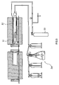
After eluting the cobalt, the obtained aqueous solution of cobalt chloride M is evaporated to dryness to obtain cobalt chloride or hydrates thereof (Step S106). Then, the obtained cobalt chloride or hydrates thereof are heated to 623 K to less than 873 K (350° C. to less than 600° C.) in a hydrogen atmosphere by using an equipment as shown in FIG. 6 (Step S107). Thus, the cobalt chloride or hydrates thereof will react as shown in the chemical formula 2 to obtain cobalt. The equipment shown in FIG. 6 includes a heating furnace 31 and a reaction pipe 32 located within the heating furnace 31. Hydrogen gas 33 is supplied through a first end part of the reaction pipe 32, and hydrogen chloride gas generated by the reaction is discharged through a second end part. The discharged gas is send to a processing part 34.
CoCl2(solid)+H2(gas)=Co(solid)+2HCl(gas)  (2)
Less than 623 K cobalt chloride cannot react sufficiently, and the reactions at 873 K and above may increase the cost and require complicated equiptments. Thus, it is preferred in a range of 623 k to less than 873 K in order to react the cobalt chloride sufficiently. FIG. 7 shows the relationship between the heating temperature and the reaction rate (reduction rate). In FIG. 7, the abscissas represent times and the ordinates represent rates of reduction. The rates of reduction are obtained by concentration changes of the collected hydrogen chloride based on the theory that 2 moles of hydrogen chloride are generated by reduction of 1 mole of cobalt as shown in the chemical formula 2. FIG. 7 also shows that the cobalt can sufficiently be reduced at 623 K to less than 873 K.
After reacting of the cobalt chloride, the obtained cobalt is molten with plasma arc using a plasma generation gas containing active hydrogen, in order to remove at least one of impurities selected from the group consisting of oxygen, nitrogen, carbon (C), sulfur, halogen, alkaline metals, and alkaline-earth metals (Step S108). Thus, the steps described above can provide the high purity cobalt and the high purity cobalt targets according to the embodiment.
Further, the high purity cobalt and the high purity cobalt targets according to the embodiment may be obtained by the following procedure for separating impurities from the aqueous solution of cobalt chloride M.
First, while injecting the inert gas into the aqueous solution of cobalt chloride M, the aqueous solution of cobalt chloride M is contacted with the metal 11 to convert the divalent copper ions to the monovalent copper ions (Step S102). Then, the concentration of hydrochloric acid of the aqueous solution of cobalt chloride M is adjusted from 7 kmol/m3 to 11 kmol/m3, and the cobalt is contacted with the anion exchange resins 21 to absorb the cobalt thereon and separate the cobalt from the impurities such as titanium (Step S104). Then, to separate the cobalt from the impurities such as molybdenum absorbed on the anion exchange resins 21, 2.5 kmol/m3 to 5 kmol/m3 of hydrochloric acid solution is passed through the column 22 to elute the cobalt from the anion exchange resins 21 (Step S105). And then, the concentration of hydrochloric acid of the aqueous solution of cobalt chloride M is adjusted from 0.1 kmol/m3 to 3 kmol/m3 (Step S101), and the aqueous solution of cobalt chloride M is contacted with the anion exchange resins 21 to absorb the copper and separate the copper from the aqueous solution of cobalt chloride M (Step S103).
In addition, after converting the divalent copper ions to the monovalent copper ions (Step S102), the following procedure may be performed, that is, adjusting the concentration of hydrochloric acid of the aqueous solution of cobalt chloride M, contacting the aqueous solution of cobalt chloride M with the anion exchange resins 21 to absorb the cobalt thereon to separate the impurities such as titanium (Step S104), eluting the cobalt from the column filled up with the anion exchange resins 21 with a 0.1 kmol/m3 to 3 kmol/m3 of hydrochloric acid solution to separate the cobalt with the impurities such as copper absorbed on the anion exchange resins 21, adjusting the concentration of hydrochloric acid of the aqueous solution of cobalt chloride M from 2.5 kmol/m3 to 5 kmol/m3, contacting the aqueous solution of cobalt chloride M with the anion exchange resins 21 to absorb the impurities such as iron, molybdenum, and tungsten to separate the impurities from the aqueous solution of cobalt chloride M.
In addition, the concentration of the hydrochloric acid solution for eluting the cobalt absorbed on the anion exchange resins 21 may be adjust from 2.5 kmol/m3 to 3 kmol/m3 to separate the impurities such as iron, molybdenum, and tungsten as well as the copper.
Furthermore, the following procedure may be performed, that is, adjusting the concentration of hydrochloric acid of the aqueous solution of cobalt chloride M, contacting the aqueous solution of cobalt chloride M with the anion exchange resins 21 to absorb the cobalt to separate the impurities such as titanium (Step S104), eluting the cobalt from the column filled up with the anion exchange resins 21 with the adjusted concentration of hydrochloride acid solution to separate impurities such as molybdenum (Step S105), converting the divalent copper ions to the monovalent copper ions (Step S102), adjusting the concentration of the aqueous solution of cobalt chloride M, and contacting the aqueous solution of cobalt chloride M with the anion exchange resins 21 to absorb and separate the copper (Step S103). It should be noted that impurities may be contaminated in the converting step. The procedures other than the latest procedure are preferred.
As described above, in the high purity cobalt and the high purity cobalt targets according to the invention, the contents of copper may be reduced to 50 mass ppb or less. Therefore, the high purity cobalt or the cobalt targets according to the invention may not be responsible for short circuit of devices such as semiconductor devices and can be applied to the semiconductor devices for the enhancement of properties. Moreover, the high purity cobalt and the high purity cobalt targets can use for devices such as magnetic recording mediums, magnetic recording heads, devices using environmental semiconductor, and the like for the enhancement of properties.
Moreover, according to the method of manufacturing the high purity cobalt, the divalent copper ions is converted to the monovalent copper ions and the concentrations of the hydrochloric acid are adjusted from 0.1 kmol/m3 to 3 kmol/m3. Therefore, the copper may be absorbed on the anion exchange resins and be separated from the aqueous solution of cobalt chloride easily and the high purity cobalt and the high purity cobalt targets with low concentrations of copper can be obtained easily and surely.
Furthermore, cobalt chloride or hydrates thereof are heated to the temperature of 623 K to less than 873K in a hydrogen atmosphere, and the cobalt can be easily and surely obtained at low temperature. Therefore, the embodiment provides a lower processing cost and compact manufacturing equiptments.
The invention will be further described in detail by reference to FIGS. 1 to 6. In the following examples, the same reference numbers and signs will be used for equivalents of the substances in the above embodiments.
EXAMPLE
First, in order to prepare an aqueous solution of cobalt chloride M, scrap cobalt used as a material was dissolved into 1.5 kmol/m3 of hydrochloric acid solution until the concentration of the cobalt reached 0.34 kmol/m3 (20 g/dm3) (Step S101). Then, powdered cobalt 11 was added to the aqueous solution of cobalt chloride M, and inert gas was injected into the solution M with agitating, as shown in FIG. 3, to convert divalent copper ions to monovalent copper ions (Step S102). Then, as shown in FIG. 4, the aqueous solution of cobalt chloride M was contacted with anion exchange resins 21 to absorb the copper and separate the copper from the aqueous solution of cobalt chloride M (Step S103).
After separating the copper, the concentration of hydrochloric acid of the aqueous solution of cobalt chloride M was adjusted to 9 kmol/m3, and the aqueous solution of cobalt chloride M was contacted with the anion exchange resins 21 to absorb the cobalt and separate impurities such as titanium (Step S104). Then, the cobalt was eluted from the column filled up with the anion exchange resins 21 with 4 kmol/m3 of hydrochloric acid solution to separate impurities such as molybdenum (Step S105).
After eluting the cobalt from the column filled up with the anion exchange resins 21, the obtained aqueous solution of cobalt chloride M was evaporated to dryness to obtain cobalt chloride or hydrates thereof (Step S106). And, as shown in FIG. 6, the obtained cobalt chloride or hydrates thereof were heated to 743 K in a hydrogen atmosphere to obtain cobalt (Step S107). FIG. 8 shows a photograph of cobalt particles obtained in the Step S107. The cobalt was sponge-like rather than powdered as shown in FIG. 8. The cobalt obtained in the Step S107 was molten with plasma arc containing active hydrogen to remove impurities such as oxygen (Step S108) to obtain high purity cobalt.
Quantities of purities contained in the obtained high purity cobalt were determined by Glow Discharge Mass Spectroscopy and residual resistivity ratio was calculated. Table 1 shows the results. As shown in Table 1, the copper concentration was as very low as 50 mass ppb or less, and the value of purity was as very high as 99.9997%, and the residual resistivity ratio was as very high as 207.
TABLE 1
Concen- Concen- Concen-
tration tration tration
Ele- (mass Ele- (mass Ele- (mass
ment ppm) ment ppm) ment ppm)
Concentration of Al 0.035 Fe 0.570 Rh <0.010
impurities As 0.700 Ga <0.020 Ru 0.020
B <0.010 Hf 0.010 Sb <0.020
Ba <0.010 In 0.005 Si <0.010
Be <0.010 K 0.010 Sn 0.050
Bi <0.010 Li <0.010 Th 0.001
Ca 0.045 Mg <0.010 Ti <0.010
Cd <0.050 Mn <0.010 U 0.002
Cl <0.050 Mo <0.050 V 0.080
Cr 0.026 Na <0.010 Zn <0.050
Cu 0.045 Ni 0.720 Zr <0.010
F <0.050 P <0.050 Pb <0.010
Purity 99.9997%
Residual resistivity 207
ratio
It is found that due to converting divalent copper ions to monovalent copper ions and adjusting the concentration of hydrochloric acid from 0.1 kmol/m3 to 3 kmol/m3, copper could be easily separated from the aqueous solution of cobalt chloride, and the high purity cobalt having the concentration of copper reduced to 50 mass ppb or less could be obtained easily.
As described above, the invention is explained by the embodiments and examples. These embodiments and examples are not meant to limit the scope of the invention and variations within the concepts of the invention are apparent. For example, the heating temperature of cobalt chloride or hydrates thereof in a hydrogen atmosphere for generating cobalt may be 623 K to less than 873K as described in the above embodiments and examples, or may be 873K or more.
Moreover, impurities other than copper may be removed by the methods as described in the above embodiments and example, or by other conventional methods.
Furthermore, the method of generating cobalt by heating cobalt chloride or hydrates thereof from 623 K to less than 873K in a hydrogen atmosphere is applicable to other methods of separating the impurities from the aqueous solution of cobalt chloride as well as the methods as described in the above embodiments and examples.
As described above, in the high purity cobalt and the high purity cobalt targets according to the invention, the contents of copper that causes influences such as a short circuit may be reduced to 50 mass ppb or less. Therefore, the high purity cobalt or the high purity cobalt targets according to the invention applied to semiconductor devices may not be responsible for short circuit of semiconductor devices and can provide the enhancement of properties of the semiconductor devices. Moreover, the high purity cobalt and the high purity cobalt targets can be used for devices such as magnetic recording mediums, magnetic recording heads, devices using environmental semiconductor and the like for the enhancement of properties.
Moreover, according to the method of manufacturing the high purity cobalt of the invention, the divalent copper ions are converted to the monovalent copper ions and the concentration of the hydrochloric acid is adjusted from 0.1 kmol/m3 to 3 kmol/m3. Therefore, the copper may be absorbed on the anion exchange resins and be separated from the aqueous solution of cobalt chloride easily. In addition, the high purity cobalt and the high purity cobalt targets with low concentration of copper can be obtained easily and surely.
Furthermore, according to the invention, cobalt chloride or hydrates thereof are heated to the temperature of 623 K to less than 873K in hydrogen atmosphere, and the cobalt can be easily and surely obtained at low temperature. Therefore, the invention provides a lower processing cost and compact manufacturing equiptments.
Obviously many modifications and variation of the present invention are possible in the light of the above teachings. It is therefore to be understood that within the scope of the appended claims the invention may be practiced otherwise than as specifically described.

Claims (5)

What is claimed is:
1. A method of manufacturing high purity cobalt comprising the steps of:
converting divalent copper ions as impurities contained in an aqueous solution of cobalt chloride to monovalent copper ions, wherein the converting step comprises injecting an inert gas into the aqueous solution of cobalt chloride and contacting the aqueous solution of cobalt chloride with elemental cobalt;
adjusting a concentration of hydrochloric acid in a range of 0.1 kmol/m3 to 3 kmol/m3; and
separating the monovalent copper ions from the aqueous solution of cobalt chloride by using anion exchange resins.
2. A method of manufacturing high purity cobalt according to claim 1, comprising the steps of;
converting divalent copper ions as impurities contained in the aqueous solution of cobalt chloride to monovalent copper ions;
adjusting a concentration of hydrochloric acid in the aqueous solution of cobalt chloride in a range of 0.1 kmol/m3 to 3 kmol/m3; and
separating the monovalent copper ions from the aqueous solution of cobalt chloride by using the anion exchange resins after the steps of converting the divalent copper ions to the monovalent copper ions and adjusting the concentration of hydrochloric acid.
3. A method of manufacturing high purity cobalt according to claim 1, wherein impurities of at least one selected from the group consisting of zinc, technetium, ruthenium, palladium, silver, cadmium, indium, tin, rhenium, osmium, iridium, platinum, gold, mercury, thallium, lead, bismuth, and polonium are separated from the aqueous solution of cobalt chloride in the step of separating the monovalent copper ions.
4. A method of manufacturing high purity cobalt according to claim 1, further comprising the steps of:
obtaining cobalt chloride or hydrates thereof from the aqueous solution of cobalt chloride which the impure copper is separated therefrom; and
heating the cobalt chloride or the hydrates thereof from 623 K to less than 873 K in a hydrogen atmosphere to obtain cobalt.
5. A method of manufacturing high purity cobalt according to claim 4, further comprising the step of melting the cobalt obtained in the heating step with plasma arc using a plasma generation gas containing active hydrogen in order to remove impurities of at least one selected from the group consisting of oxygen, nitrogen, carbon, sulfur, halogen, alkaline metals, and alkaline-earth metals.
US10/803,506 2000-09-29 2004-03-17 High purity cobalt, method of manufacturing thereof, and high purity cobalt targets Expired - Lifetime US7279024B2 (en)

Priority Applications (1)

Application Number Priority Date Filing Date Title
US10/803,506 US7279024B2 (en) 2000-09-29 2004-03-17 High purity cobalt, method of manufacturing thereof, and high purity cobalt targets

Applications Claiming Priority (4)

Application Number Priority Date Filing Date Title
JPP2000-338288 2000-09-29
JP2000338288A JP4691241B2 (en) 2000-09-29 2000-09-29 Method for producing high purity cobalt and method for purifying cobalt chloride
US09/966,861 US6740290B2 (en) 2000-09-29 2001-09-28 High purity cobalt, method of manufacturing thereof, and high purity cobalt targets
US10/803,506 US7279024B2 (en) 2000-09-29 2004-03-17 High purity cobalt, method of manufacturing thereof, and high purity cobalt targets

Related Parent Applications (1)

Application Number Title Priority Date Filing Date
US09/966,861 Division US6740290B2 (en) 2000-09-29 2001-09-28 High purity cobalt, method of manufacturing thereof, and high purity cobalt targets

Publications (2)

Publication Number Publication Date
US20070180953A1 US20070180953A1 (en) 2007-08-09
US7279024B2 true US7279024B2 (en) 2007-10-09

Family

ID=18813514

Family Applications (2)

Application Number Title Priority Date Filing Date
US09/966,861 Expired - Lifetime US6740290B2 (en) 2000-09-29 2001-09-28 High purity cobalt, method of manufacturing thereof, and high purity cobalt targets
US10/803,506 Expired - Lifetime US7279024B2 (en) 2000-09-29 2004-03-17 High purity cobalt, method of manufacturing thereof, and high purity cobalt targets

Family Applications Before (1)

Application Number Title Priority Date Filing Date
US09/966,861 Expired - Lifetime US6740290B2 (en) 2000-09-29 2001-09-28 High purity cobalt, method of manufacturing thereof, and high purity cobalt targets

Country Status (3)

Country Link
US (2) US6740290B2 (en)
JP (1) JP4691241B2 (en)
KR (2) KR100817003B1 (en)

Families Citing this family (14)

* Cited by examiner, † Cited by third party
Publication number Priority date Publication date Assignee Title
JP4691241B2 (en) * 2000-09-29 2011-06-01 ソニー株式会社 Method for producing high purity cobalt and method for purifying cobalt chloride
JP4276444B2 (en) * 2003-01-16 2009-06-10 Tdk株式会社 Iron silicide film manufacturing method and apparatus, photoelectric conversion element manufacturing method and apparatus, and photoelectric conversion apparatus manufacturing method and apparatus
JP4954479B2 (en) * 2004-01-30 2012-06-13 ソニー株式会社 Method for producing high purity electrolytic iron and method for producing high purity electrolytic cobalt
KR100772967B1 (en) * 2006-06-21 2007-11-02 한국과학기술연구원 Selective separation of cobalt and nickel using an ion exchange resin
JP5395512B2 (en) * 2009-05-26 2014-01-22 オリンパスイメージング株式会社 Imaging device
JP5154622B2 (en) * 2010-03-02 2013-02-27 Jx日鉱日石金属株式会社 Method for recovering cobalt contained in copper-containing aqueous solution
JP5530270B2 (en) * 2010-06-29 2014-06-25 Jx日鉱日石金属株式会社 Cobalt powder and method for producing the same
JP5741795B2 (en) 2010-11-09 2015-07-01 セイコーエプソン株式会社 Projector and control method thereof
JP5373867B2 (en) * 2011-08-23 2013-12-18 株式会社田中化学研究所 Method for producing nickel oxide
RU2534323C1 (en) * 2013-08-08 2014-11-27 Федеральное государственное бюджетное учреждение науки Институт химии и технологии редких элементов и минерального сырья им. И.В. Тананаева Кольского научного центра Российской академии наук (ИХТРЭМС КНЦ РАН) Metallic cobalt obtaining method
JP5993097B2 (en) * 2013-12-02 2016-09-14 Jx金属株式会社 Method for producing high purity cobalt chloride
US9741577B2 (en) * 2015-12-02 2017-08-22 International Business Machines Corporation Metal reflow for middle of line contacts
KR102044481B1 (en) 2018-02-12 2019-12-02 주식회사 영풍 Method of recovering cobalt from byproduct generated in smelting of zinc
JP7249317B2 (en) * 2020-08-07 2023-03-30 株式会社 イージーエス METHOD FOR SEPARATING METAL AND METAL SEPARATING DEVICE

Citations (20)

* Cited by examiner, † Cited by third party
Publication number Priority date Publication date Assignee Title
US3661564A (en) * 1969-11-19 1972-05-09 Nickel Le Extraction of cobalt and nickel from laterite
US4039612A (en) * 1975-06-09 1977-08-02 Imperial Chemical Industries Limited Process for extracting cobalt, copper or zinc values using a 1-alkyl substituted benzimidazole
US4108640A (en) * 1975-08-25 1978-08-22 Sherritt Gordon Mines Limited Hydrometallurgical process for the production of cobalt powder from mixed metal sulphides
US4178172A (en) * 1977-07-15 1979-12-11 Outokumpu Oy Process for the production of extra fine cobalt powder
US4214896A (en) * 1979-05-14 1980-07-29 Gte Products Corporation Process for producing cobalt metal powder
US4214894A (en) * 1979-05-14 1980-07-29 Gte Products Corporation Method for producing cobalt metal powder
US4218240A (en) * 1979-05-14 1980-08-19 Gte Products Corporation Method for producing cobaltic hexammine compounds and cobalt metal powder
US4233063A (en) * 1979-05-14 1980-11-11 Gte Products Corporation Process for producing cobalt powder
US4381937A (en) * 1981-09-21 1983-05-03 Gte Products Corporation Method for producing cobalt metal powder
US4395278A (en) * 1980-09-29 1983-07-26 Gte Products Corporation Method for producing cobalt metal powder
US4469505A (en) * 1980-11-19 1984-09-04 Gte Products Corporation Method for producing cobalt metal powder
US4526611A (en) * 1983-03-14 1985-07-02 Toho Zinc Co., Ltd. Process for producing superfines of metal
US4578251A (en) * 1985-04-01 1986-03-25 Gte Products Corporation Removal of chromium from cobalt
US4816069A (en) * 1988-05-23 1989-03-28 Gte Products Corporation Method for converting cobalt to cobalt metal powder
US5154757A (en) * 1991-10-28 1992-10-13 Gte Products Corporation Method of making pure cobalt metal powder substantially free of divalent cationic impurities
US5667665A (en) * 1995-03-14 1997-09-16 Japan Energy Corporation Process of producing high purity cobalt
US5728197A (en) * 1996-07-17 1998-03-17 Nanodyne Incorporated Reclamation process for tungsten carbide/cobalt using acid digestion
JPH11260410A (en) * 1998-03-06 1999-09-24 Hitachi Maxell Ltd Polymer electrolyte battery
US6346137B1 (en) * 1995-10-27 2002-02-12 H. C. Starck Gmbh & Co. Kg Ultrafine cobalt metal powder, process for the production thereof and use of the cobalt metal powder and of cobalt carbonate
US20020117025A1 (en) * 2000-09-29 2002-08-29 Masahito Uchikoshi High purity cobalt, method of manufacturing thereof, and high purity cobalt targets

Family Cites Families (10)

* Cited by examiner, † Cited by third party
Publication number Priority date Publication date Assignee Title
KR940007372B1 (en) * 1992-09-22 1994-08-16 김병남 Method of purification cobalt
JP3065193B2 (en) * 1992-12-24 2000-07-12 株式会社ジャパンエナジー High purity cobalt sputtering target
ATE143920T1 (en) * 1993-08-12 1996-10-15 Starck H C Gmbh Co Kg COBALT COBALT OXIDE POWDER, METHOD FOR THE PRODUCTION THEREOF AND USE THEREOF
JPH09501738A (en) * 1993-08-13 1997-02-18 ジョンソン マッセイ エレクトロニクス,インコーポレイティド Manufacturing method of high purity element
JPH08253888A (en) * 1995-03-14 1996-10-01 Japan Energy Corp Production of high purity cobalt
JP3065242B2 (en) * 1996-02-23 2000-07-17 株式会社ジャパンエナジー Method for producing high-purity cobalt and high-purity cobalt sputtering target
DE19519329C1 (en) * 1995-05-26 1996-11-28 Starck H C Gmbh Co Kg Cobalt metal agglomerates, process for their preparation and their use
JPH09272970A (en) * 1996-04-05 1997-10-21 Japan Energy Corp High purity cobalt sputtering target and its manufacture
US6391172B2 (en) * 1997-08-26 2002-05-21 The Alta Group, Inc. High purity cobalt sputter target and process of manufacturing the same
JP3151194B2 (en) * 1999-03-19 2001-04-03 株式会社ジャパンエナジー Cobalt purification method

Patent Citations (22)

* Cited by examiner, † Cited by third party
Publication number Priority date Publication date Assignee Title
US3661564A (en) * 1969-11-19 1972-05-09 Nickel Le Extraction of cobalt and nickel from laterite
US4039612A (en) * 1975-06-09 1977-08-02 Imperial Chemical Industries Limited Process for extracting cobalt, copper or zinc values using a 1-alkyl substituted benzimidazole
US4108640A (en) * 1975-08-25 1978-08-22 Sherritt Gordon Mines Limited Hydrometallurgical process for the production of cobalt powder from mixed metal sulphides
US4178172A (en) * 1977-07-15 1979-12-11 Outokumpu Oy Process for the production of extra fine cobalt powder
US4214896A (en) * 1979-05-14 1980-07-29 Gte Products Corporation Process for producing cobalt metal powder
US4214894A (en) * 1979-05-14 1980-07-29 Gte Products Corporation Method for producing cobalt metal powder
US4218240A (en) * 1979-05-14 1980-08-19 Gte Products Corporation Method for producing cobaltic hexammine compounds and cobalt metal powder
US4233063A (en) * 1979-05-14 1980-11-11 Gte Products Corporation Process for producing cobalt powder
US4395278A (en) * 1980-09-29 1983-07-26 Gte Products Corporation Method for producing cobalt metal powder
US4469505A (en) * 1980-11-19 1984-09-04 Gte Products Corporation Method for producing cobalt metal powder
US4381937A (en) * 1981-09-21 1983-05-03 Gte Products Corporation Method for producing cobalt metal powder
US4526611A (en) * 1983-03-14 1985-07-02 Toho Zinc Co., Ltd. Process for producing superfines of metal
US4578251A (en) * 1985-04-01 1986-03-25 Gte Products Corporation Removal of chromium from cobalt
US4816069A (en) * 1988-05-23 1989-03-28 Gte Products Corporation Method for converting cobalt to cobalt metal powder
US5154757A (en) * 1991-10-28 1992-10-13 Gte Products Corporation Method of making pure cobalt metal powder substantially free of divalent cationic impurities
US5667665A (en) * 1995-03-14 1997-09-16 Japan Energy Corporation Process of producing high purity cobalt
US5810983A (en) * 1995-03-14 1998-09-22 Japan Energy Corporation High purity cobalt sputtering targets
US6346137B1 (en) * 1995-10-27 2002-02-12 H. C. Starck Gmbh & Co. Kg Ultrafine cobalt metal powder, process for the production thereof and use of the cobalt metal powder and of cobalt carbonate
US5728197A (en) * 1996-07-17 1998-03-17 Nanodyne Incorporated Reclamation process for tungsten carbide/cobalt using acid digestion
JPH11260410A (en) * 1998-03-06 1999-09-24 Hitachi Maxell Ltd Polymer electrolyte battery
US20020117025A1 (en) * 2000-09-29 2002-08-29 Masahito Uchikoshi High purity cobalt, method of manufacturing thereof, and high purity cobalt targets
US6740290B2 (en) * 2000-09-29 2004-05-25 Sony Corporation High purity cobalt, method of manufacturing thereof, and high purity cobalt targets

Also Published As

Publication number Publication date
KR100860957B1 (en) 2008-09-30
KR20020025768A (en) 2002-04-04
JP2002105633A (en) 2002-04-10
US6740290B2 (en) 2004-05-25
KR20070108503A (en) 2007-11-12
KR100817003B1 (en) 2008-03-27
US20020117025A1 (en) 2002-08-29
US20070180953A1 (en) 2007-08-09
JP4691241B2 (en) 2011-06-01

Similar Documents

Publication Publication Date Title
KR100860957B1 (en) Method of manufacturing high purity cobalt
Navarro et al. Adsorption of antimony and arsenic from a copper electrorefining solution onto activated carbon
KR100854264B1 (en) Method Of Manufacturing High Purity Iron
EP1026283B1 (en) Method for preparing high purity ruthenium sputtering target
JPH01502976A (en) Ion exchange method for separation of scandium and thorium
JP5751572B2 (en) Indium with low alpha dose or alloys containing indium
Vuchkova et al. Behaviour of the dithiocarbamate complexes of arsenic, antimony, bismuth, mercury, lead, tin and selenium in methanol with a hydride generator
JP5291968B2 (en) Ruthenium recovery method
JP4954479B2 (en) Method for producing high purity electrolytic iron and method for producing high purity electrolytic cobalt
Uchikoshi et al. Copper purification by anion-exchange separation in chloride media
US3192011A (en) Process for producing high purity rhenium compounds
JP3206432B2 (en) Low alpha low oxygen metal scandium and method for producing the same
JP7006332B2 (en) How to make gold powder
Matsui et al. Preconcentration of antimony (III) from water with thionalide loaded on glass beads with the aid of collodion
Gong et al. Comparison of chemical modifiers used for the determination of gold in ores by electrothermal atomic absorption spectrometry
Fouché et al. Separation of rhodium from iridium by extraction from molten cyanide
CA1096178A (en) Recovery of silver from cuprous chloride solutions by amalgamation
JPS6252020B2 (en)
JP3411212B2 (en) Method for producing high-purity Ir material for forming thin film
JP2001081507A (en) High purity cobalt powder and method of producing the same
Kozuka et al. Determination of uranium and thorium in aluminum by inductively coupled plasma mass spectrometry
GB1598250A (en) Recovery of copper and/or silver
Kékesi International Motivation and Cooperation for Research in the Ultra-High Purification of Metals
Kudermann Charakterisierung von hochreinem Aluminium
FURNACE with their direct application to aqueous or solid samples. Although an investigation into interference effects has been reported with the filament atom reservoir*, only

Legal Events

Date Code Title Description
STCF Information on status: patent grant

Free format text: PATENTED CASE

FEPP Fee payment procedure

Free format text: PAYER NUMBER DE-ASSIGNED (ORIGINAL EVENT CODE: RMPN); ENTITY STATUS OF PATENT OWNER: LARGE ENTITY

Free format text: PAYOR NUMBER ASSIGNED (ORIGINAL EVENT CODE: ASPN); ENTITY STATUS OF PATENT OWNER: LARGE ENTITY

FPAY Fee payment

Year of fee payment: 4

FPAY Fee payment

Year of fee payment: 8

MAFP Maintenance fee payment

Free format text: PAYMENT OF MAINTENANCE FEE, 12TH YEAR, LARGE ENTITY (ORIGINAL EVENT CODE: M1553); ENTITY STATUS OF PATENT OWNER: LARGE ENTITY

Year of fee payment: 12