US7279236B2 - Luminescent-film-coated product - Google Patents
Luminescent-film-coated product Download PDFInfo
- Publication number
- US7279236B2 US7279236B2 US11/077,258 US7725805A US7279236B2 US 7279236 B2 US7279236 B2 US 7279236B2 US 7725805 A US7725805 A US 7725805A US 7279236 B2 US7279236 B2 US 7279236B2
- Authority
- US
- United States
- Prior art keywords
- film
- luminescent
- coated product
- product according
- layer
- Prior art date
- Legal status (The legal status is an assumption and is not a legal conclusion. Google has not performed a legal analysis and makes no representation as to the accuracy of the status listed.)
- Expired - Fee Related
Links
Images


Classifications
-
- C—CHEMISTRY; METALLURGY
- C09—DYES; PAINTS; POLISHES; NATURAL RESINS; ADHESIVES; COMPOSITIONS NOT OTHERWISE PROVIDED FOR; APPLICATIONS OF MATERIALS NOT OTHERWISE PROVIDED FOR
- C09D—COATING COMPOSITIONS, e.g. PAINTS, VARNISHES OR LACQUERS; FILLING PASTES; CHEMICAL PAINT OR INK REMOVERS; INKS; CORRECTING FLUIDS; WOODSTAINS; PASTES OR SOLIDS FOR COLOURING OR PRINTING; USE OF MATERIALS THEREFOR
- C09D5/00—Coating compositions, e.g. paints, varnishes or lacquers, characterised by their physical nature or the effects produced; Filling pastes
- C09D5/22—Luminous paints
-
- Y—GENERAL TAGGING OF NEW TECHNOLOGICAL DEVELOPMENTS; GENERAL TAGGING OF CROSS-SECTIONAL TECHNOLOGIES SPANNING OVER SEVERAL SECTIONS OF THE IPC; TECHNICAL SUBJECTS COVERED BY FORMER USPC CROSS-REFERENCE ART COLLECTIONS [XRACs] AND DIGESTS
- Y10—TECHNICAL SUBJECTS COVERED BY FORMER USPC
- Y10T—TECHNICAL SUBJECTS COVERED BY FORMER US CLASSIFICATION
- Y10T428/00—Stock material or miscellaneous articles
- Y10T428/24—Structurally defined web or sheet [e.g., overall dimension, etc.]
- Y10T428/24802—Discontinuous or differential coating, impregnation or bond [e.g., artwork, printing, retouched photograph, etc.]
- Y10T428/24893—Discontinuous or differential coating, impregnation or bond [e.g., artwork, printing, retouched photograph, etc.] including particulate material
- Y10T428/24901—Discontinuous or differential coating, impregnation or bond [e.g., artwork, printing, retouched photograph, etc.] including particulate material including coloring matter
-
- Y—GENERAL TAGGING OF NEW TECHNOLOGICAL DEVELOPMENTS; GENERAL TAGGING OF CROSS-SECTIONAL TECHNOLOGIES SPANNING OVER SEVERAL SECTIONS OF THE IPC; TECHNICAL SUBJECTS COVERED BY FORMER USPC CROSS-REFERENCE ART COLLECTIONS [XRACs] AND DIGESTS
- Y10—TECHNICAL SUBJECTS COVERED BY FORMER USPC
- Y10T—TECHNICAL SUBJECTS COVERED BY FORMER US CLASSIFICATION
- Y10T428/00—Stock material or miscellaneous articles
- Y10T428/25—Web or sheet containing structurally defined element or component and including a second component containing structurally defined particles
- Y10T428/252—Glass or ceramic [i.e., fired or glazed clay, cement, etc.] [porcelain, quartz, etc.]
-
- Y—GENERAL TAGGING OF NEW TECHNOLOGICAL DEVELOPMENTS; GENERAL TAGGING OF CROSS-SECTIONAL TECHNOLOGIES SPANNING OVER SEVERAL SECTIONS OF THE IPC; TECHNICAL SUBJECTS COVERED BY FORMER USPC CROSS-REFERENCE ART COLLECTIONS [XRACs] AND DIGESTS
- Y10—TECHNICAL SUBJECTS COVERED BY FORMER USPC
- Y10T—TECHNICAL SUBJECTS COVERED BY FORMER US CLASSIFICATION
- Y10T428/00—Stock material or miscellaneous articles
- Y10T428/26—Web or sheet containing structurally defined element or component, the element or component having a specified physical dimension
Definitions
- the present invention relates to products coated with a highly shiny film containing a phosphorescent material and/or a fluorescent material.
- the luminescent-film-coated products according to the present invention are used for, for example, warning/safety signs, position signs, and ornaments.
- shiny pigments including aluminum flake powder, graphite flake particles, glass flakes, silver-coated glass flakes, and mica flake particles or glass flakes coated with a metal oxide such as titanium dioxide and iron oxide.
- a metal oxide such as titanium dioxide and iron oxide.
- Paintwork using paints containing the shiny pigments, line drawings or prints using inks containing the shiny pigments, or resin products produced by molding resin compositions containing the shiny pigments provide a wide variety of beautiful, distinctive appearances in combination with the color tone of a base material (or a substrate for the film).
- the shiny pigments have a wide range of applications, including automobiles, motorcycles, office automation equipment, cellular phones, household electrical appliances, various printed matters, and writing instruments.
- products coated with a film containing a phosphorescent or fluorescent material have a wide variety of applications.
- the applications include glow-in-the-dark signs; switches and outlets; flashlights; darkroom items; non-slip stair treads; handrails; baseboards; tiles; floor faces; wall signs; phosphorescent signs; direction signs; various signs for shelter items, survival kits, fire extinguishers, fire hydrants, fire alarms, life preservers, smoke control systems, and so forth; markings for indicating the number of stairs; ornaments such as ashtrays, lighters, cigarette cases, necklaces, earrings, tablecloths, door curtains, lampshades, wallpaper, and fibers; toys; angling gear; stationery; novelties; and fishing gear.
- Japanese Unexamined Patent Application Publication No. 2001-158867 discloses an ink composition produced by mixing a phosphorescent or fluorescent material, a shiny pigment, and a resin to improve the design of handwriting.
- glass flakes coated with nickel or silver are used as the shiny pigment.
- Japanese Unexamined Patent Application Publication No. 11-130992 discloses techniques for improving the visibility of films using a coating material containing a reflective agent made of glass particles or resin beads and a luminescent agent (fluorescent material).
- the techniques disclosed include (1) a monolayer luminescent film containing a reflective agent and a luminescent agent, (2) a bilayer luminescent film including a basecoat containing a luminescent agent and a topcoat containing a reflective agent, and (3) a bilayer luminescent film including a basecoat containing a reflective agent and a topcoat containing a luminescent agent.
- An object of the present invention is to provide a product coated with a luminescent film having good visibility and design with a suitable combination of a phosphorescent or fluorescent material and a shiny pigment.
- Another object of the present invention is to provide a luminescent-film-coated product that has good visibility and design and is suitable for, for example, warning/safety signs, position signs, and ornaments using the above luminescent film having good visibility and design.
- a luminescent-film-coated product includes a substrate, a first layer that is formed on the substrate and is made of a transparent resin matrix containing a phosphorescent material and/or a fluorescent material, and a second layer that is formed on the first layer and is made of a transparent resin matrix containing a shiny pigment made of glass flakes coated with a high-refractive-index metal oxide.
- a luminescent-film-coated product includes a substrate and a layer that is formed on the substrate and is made of a transparent resin matrix containing a phosphorescent material and/or a fluorescent material and a shiny pigment made of glass flakes coated with a high-refractive-index metal oxide.
- a luminescent-film-coated product includes a substrate, a first layer that is formed on the substrate and is made of a transparent resin matrix containing a shiny pigment, and a second layer that is formed on the first layer and is made of a transparent resin matrix containing a phosphorescent material and/or a fluorescent material.
- the shiny pigment is made of glass flakes coated with one or more materials selected from the group consisting of silver, gold, nickel, and high-refractive-index metal oxides, and has a maximum reflectance in the visible light region of 30% or more.
- a suitable combination and arrangement of a phosphorescent material and/or a fluorescent material and a shiny pigment can produce a luminescent film that emits clear phosphorescent or fluorescent light and shows higher shininess.
- the use of the luminescent film therefore provides better design and visibility for products for various applications.
- the luminescent film can contribute to improvements in the safety of bicycle riding or car driving at nighttime.
- a luminescent-film-coated product has a multilayer luminescent film including a first layer that is formed on a substrate and is made of a transparent resin matrix containing a phosphorescent material and/or a fluorescent material and a second layer that is formed on the first layer and is made of a transparent resin matrix containing a shiny pigment made of glass flakes coated with a high-refractive-index metal oxide to allow the shiny pigment to enhance the shininess of the film without blocking light emitted from the phosphorescent material and/or the fluorescent material.
- the top layer (second layer), which contains the shiny pigment, is composed of the transparent resin matrix containing the shiny pigment made of the glass flakes coated with the high-refractive-index metal oxide so as not to impair the shininess based on the light emission from the phosphorescent material and/or the fluorescent material contained in the bottom layer (first layer).
- the material for the glass flakes of the shiny pigment, as a transparent base material for being coated with the high-refractive-index metal oxide is not particularly limited, and is exemplified by materials mainly containing silicon dioxide, including C-glass, E-glass, alkali-resistant glass, high-strength glass, quartz glass, and A-glass.
- C-glass and E-glass are preferred because they can be processed into glass flakes having high transparency and excellent surface smoothness. That is, while glass flakes having excellent surface smoothness can be produced by, for example, drawing molten glass into a film, the glass flakes having the above compositions have particularly excellent surface smoothness and therefore do not attenuate the light emitted from the phosphorescent material and/or the fluorescent material.
- the glass flakes preferably have an average particle diameter of 5 to 500 ⁇ m, an average thickness of 0.1 to 5 ⁇ m, and an average aspect ratio of 5 to 300, more preferably an average particle diameter of 8 to 300 ⁇ m, an average thickness of 0.2 to 2.5 ⁇ m, and an average aspect ratio of 8 to 200, still more preferably an average particle diameter of 8 to 50 ⁇ m, an average thickness of 0.5 to 2.0 ⁇ m, and an average aspect ratio of 8 to 50.
- the glass flakes have an average particle diameter below 5 ⁇ m, they aggregate readily and therefore cause difficulty in scattering visible light. If, on the other hand, the glass flakes have an average particle diameter above 500 ⁇ m, they are readily crushed when added as a filler. If the glass flakes have an average thickness below 0.1 ⁇ m, they are difficult to produce and have problems such as being readily crushed. If, on the other hand, the glass flakes have an average thickness above 5 ⁇ m, they produce irregularities on the luminescent film produced and therefore impair its appearance. If the glass flakes have an average aspect ratio below 5, they begin to show the properties as spherical particles and thus tend to cause a problem of aggregation. If, on the other hand, the glass flakes have an average aspect ratio above 300, they are readily crushed when added as a filler.
- the average particle diameter of the glass flakes may be determined by simply averaging measurements of 50 glass flakes using a laser diffraction/scattering particle size analyzer, for example Microtrac® 2 (manufactured by Nikkiso Co., Ltd.).
- the average thickness of the glass flakes may be determined by simply averaging measurements of 50 glass flakes using an electron microscope.
- the average aspect ratio of the glass flakes may be determined by dividing the average particle diameter by the average thickness.
- the glass flakes and the high-refractive-index metal oxide coatings formed on the glass flakes preferably have a difference in refractive index of 0.6 or more, more preferably 0.8 or more. At the interface between layers of different materials, generally, more reflection occurs with a larger difference in refractive index between the materials. If the difference in refractive index is 0.6 or more, the shininess can be enhanced not only by the light emission from the phosphorescent material and/or the fluorescent material, but also by the light reflection from the interfaces between the glass flakes and the metal oxide coatings.
- the refractive index of the glass flakes which differs slightly according to the composition of the glass used, normally ranges from 1.50 to 1.60, for example about 1.54.
- the transparent resin matrix and the transparent high-refractive-index metal oxide coatings for the shiny pigment preferably have a difference in refractive index of 0.6 or more, more preferably 0.8 or more.
- the transparent high-refractive-index metal oxide coatings for the shiny pigment may be made of, for example, at least one material selected from the group consisting of titanium dioxide (TiO 2 , rutile, refractive index: 2.76; anatase, refractive index: 2.52), zirconium dioxide (ZrO 2 , refractive index: 2.1 to 2.2), cerium oxide (CeO 2 , refractive index: 2.2), zinc oxide (ZnO, refractive index: 1.9 to 2.1), dialuminum trioxide (Al 2 O 3 , refractive index: 1.6 to 1.8), diantimony trioxide (Sb 2 O 3 , refractive index: 2.0 to 2.3), tin oxide (SnO 2 , refractive index: 2.0), and diiron trioxide (Fe 2 O 3 , refractive index: 2.9 to 3.2).
- TiO 2 titanium dioxide
- ZrO 2 zirconium dioxide
- CeO 2 cerium oxide
- ZnO
- rutile titanium oxide which has a refractive index of about 2.70, is preferred as the material for the transparent high-refractive-index metal oxide coatings.
- the shiny pigment preferably has a visible light transmittance of 70% or more, more preferably 80% or more. If the shiny pigment has a visible light transmittance below 70%, it deteriorates the shininess based on the light emission from the phosphorescent material and/or the fluorescent material contained in the bottom layer. In addition, the shiny pigment preferably has a maximum reflectance in the visible light region of 30% or more, more preferably 50% or more. If the reflectance is below 30%, less reflection of the light emitted from the phosphorescent material and/or the fluorescent material contained in the bottom layer occurs on the shiny pigment, thus failing to enhance the shininess of the luminescent film. The methods used for measuring the visible light transmittance and reflectance of the shiny pigment will be described later.
- the thickness of the transparent high-refractive-index metal oxide coatings in the shiny pigment is not particularly limited, though the coatings preferably have a thickness of 1 to 200 nm to achieve a visible light transmittance of 70% or more. If the thickness is below 1 nm, no reflection occurs at the interface between the glass flakes and the metal oxide coatings. If, on the other hand, the thickness exceeds 200 nm, the metal oxide grows its crystals which produce irregularities at the outer surfaces of the metal oxide coatings, resulting in larger scattering of transmitted light or reflected light. If, therefore, the thickness of the metal oxide coatings falls outside the above range, they impair the enhancement of the shininess by the light emission from the phosphorescent material and/or the fluorescent material contained in the bottom layer.
- Interference colors can be developed to provide better design by controlling the thickness of the high-refractive-index metal oxide coatings to 50 to 400 nm in terms of optical thickness (nd, wherein n is a refractive index and d is a physical thickness). Accordingly, more preferably, the high-refractive-index metal oxide coatings have a thickness of, for example, 20 to 160 nm if the material used is TiO 2 .
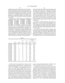
- Shiny pigments with high transparency are exemplified by Metashine® RRC series (MC5090RS, MC5090RY, MC5090RR, MC5090RB, MC5090RG, MC1080RS, MC1080RY, MC1080RR, MC1080RB, MC1080RG, MC1040RS, MC1040RY, MC1040RR, MC1040RB, MC1040RG, MC1020RS, MC1020RY, MC1020RR, MC1020RB, and MC1020RG), manufactured by Nippon Sheet Glass Co., Ltd. These pigments are produced by coating glass flakes having high surface smoothness with titanium dioxide. Table 1 shows the types of materials, sizes, and properties of the pigments.
- the shiny pigments shown in Table 1 have a visible light transmittance of 70% to 96% and a maximum reflectance in the visible light region of 30% to 45%. These pigments contain glass flakes with excellent surface smoothness, while natural or synthetic mica has a rough surface, such as a cleavage surface, thus having poor surface smoothness and showing an opaque appearance.
- the resin used for the transparent resin matrix in which the shiny pigment is dispersed may be a transparent thermosetting or thermoplastic resin with a refractive index of 1.35 to 1.65.
- thermosetting resin used include acrylic resin, silicone-modified acrylic resin, polyester resin, silicone-modified polyester resin, epoxy resin, fluorine resin, polyester-urethane curable resin, epoxy-polyester curable resin, acrylic-polyester resin, acrylic-urethane curable resin, acrylic-melamine curable resin, and polyester-melamine curable resin. These resins may be used alone or in combination.
- One or more curing agents may be added, such as polyisocyanates, amines, polyamides, polybasic acids, acid anhydrides, polysulfides, boron trifluoride, acid dihydrazides, and imidazole.
- the thermoplastic resin used include polypropylene resin; polycarbonate resin; chlorinated olefin resins such as chlorinated polyethylene and chlorinated polypropylene; thermoplastic polyester resin; thermoplastic fluorine resin; vinyl chloride resin; vinyl acetate resin; vinylidene chloride resin; vinyl resins produced by copolymerization of vinyl chloride, vinyl acetate, and vinylidene chloride; cellulose resin; and alkyd resin. These resins may be used alone or in combination. Among these resins, acrylic resin and polycarbonate resin are particularly preferred because they have high visible light transmittance.
- the content of the shiny pigment in the top layer is preferably 0.1% to 30% by mass, more preferably 0.5% to 10% by mass, of the total amount, namely 100% by mass, of the transparent resin matrix and the shiny pigment to enhance the shininess of the luminescent film by the reflection of the shiny pigment without impairing the shininess of the bottom layer.
- the phosphorescent material and/or the fluorescent material contained in the bottom layer (first layer) may be, for example, a commercially available phosphorescent pigment, fluorescent pigment, or fluorescent dye.
- the phosphorescent material used include calcium sulfate phosphors (host crystal: CaS; activator: Bi); zinc sulfate phosphors (host crystal: ZnS; activator: Cu, “GSS” manufactured by Nemoto & Co., Ltd.); phosphors containing strontium aluminate or calcium aluminate, as a host crystal, and Eu, Dy, Nd, or the like, as an activator (LumiNova® G-300 series, BG-300 series, and V-300 series, manufactured by Nemoto & Co., Ltd.; “ULTRA GLOW series” NP-2810, NP-2820, and NP-2830, manufactured by Nichia Corporation; “R-bright” B and YG, manufactured by Lead Co., Ltd.; “Chemi
- the size of the phosphorescent material and/or the fluorescent material is not particularly limited, though the average particle diameter is preferably 10 nm to 10 ⁇ m. If the phosphorescent material and/or the fluorescent material has an average particle diameter below 10 nm, it exhibits excessively poor durability and significantly decreased brightness. If, on the other hand, the phosphorescent material and/or the fluorescent material has an average particle diameter above 10 ⁇ m, it causes larger visible light scattering, thus producing a luminescent film with an opaque appearance and poor design. In addition, the phosphorescent material and/or the fluorescent material impairs the surface smoothness of the luminescent film if the luminescent film is thin.
- the combination of the phosphorescent material and/or the fluorescent material contained in the bottom layer and the shiny pigment contained in the top layer is not particularly limited.
- the phosphorescent material and/or the fluorescent material is used in combination with a shiny pigment with a color tone (reflection color tone) similar to the light emitted from the phosphorescent material and/or the fluorescent material, or a phosphorescent material and/or a fluorescent material that emits white light is used.
- the light emitted from the phosphorescent material and/or the fluorescent material is clearly visible and can enhance the shininess of the luminescent film effectively.
- the bottom layer may contain either or both of the phosphorescent material and the fluorescent material.
- the content of the phosphorescent material and/or the fluorescent material in the bottom layer (the total content if it contains both materials) is preferably 1% to 50% by mass, more preferably 1% to 20% by mass, of the total amount, namely 100% by mass, of the transparent resin matrix and the phosphorescent material and/or the fluorescent material in consideration of the enhancement of the shininess and coating strength.
- the above description of the transparent resin matrix for the top layer is also applied to the transparent resin matrix for the bottom layer.
- the same transparent resin matrix as that for the top layer is preferably used for the bottom layer so as not to impair transparency.
- the first layer which is composed of the transparent resin matrix containing the phosphorescent material and/or the fluorescent material, preferably has a thickness of 10 to 200 ⁇ m. If the bottom layer has an excessively large thickness, it exhibits considerable visible light absorption by the resin matrix. If, on the other hand, the bottom layer has an excessively small thickness, it emits low light and therefore cannot provide better design.
- the bottom layer (first layer) and the top layer (second layer) preferably have a total thickness of 15 to 250 ⁇ m. If the luminescent film has a total thickness above 250 ⁇ m, it exhibits considerable visible light absorption by the resin matrix.
- a luminescent-film-coated product has a luminescent film that is formed on a substrate and is made of a transparent resin matrix containing a phosphorescent material and/or a fluorescent material and a shiny pigment made of glass flakes coated with a high-refractive-index metal oxide to allow the shiny pigment to enhance the shininess of the film without blocking light emitted from the phosphorescent material and/or the fluorescent material.
- the above description of the luminescent film structure according to the first aspect may be applied to the description of the shiny pigment, the phosphorescent material, the fluorescent material, and the transparent resin matrix according to the second aspect.
- the content of the phosphorescent material and/or the fluorescent material in the film is preferably 1% to 50% by mass of the total amount, namely 100% by mass, of the transparent resin matrix, the phosphorescent material and/or the fluorescent material, and the shiny pigment.
- the content of the shiny pigment in the film is preferably 0.1% to 30% by mass.
- the total content of the phosphorescent material and/or the fluorescent material and the shiny pigment is preferably 1.1% to 50% by mass.
- an excessively high content of the phosphorescent material and/or the fluorescent material in the film results in a relative decrease in the content of the shiny pigment, while an excessively high content of the shiny pigment in the film results in a relative decrease in the content of the phosphorescent material and/or the fluorescent material. In either case, the resultant luminescent film has decreased shininess.
- the luminescent film which contains the phosphorescent material and/or the fluorescent material and the shiny pigment, preferably has a thickness of 15 to 250 ⁇ m for the same reason as the luminescent film according to the first aspect.
- a luminescent-film-coated product has a multilayer luminescent film including a first layer that is formed on a substrate and is made of a transparent resin matrix containing a shiny pigment and a second layer that is formed on the first layer and is made of a transparent resin matrix containing a phosphorescent material and/or a fluorescent material to allow the shiny pigment to enhance the shininess of the film without blocking light emitted from the phosphorescent material and/or the fluorescent material.
- the shiny pigment is made of glass flakes coated with one or more materials selected from the group consisting of silver, gold, nickel, and high-refractive-index metal oxides, and has a maximum reflectance in the visible light region of 30% or more.
- the shiny pigment which is contained in the bottom layer, has a maximum reflectance in the visible light region of 30% or more.
- the shiny pigment used is that used for the top layer in the luminescent film structure according to the first aspect or a shiny pigment made of glass flakes having monolayer coatings of silver, gold, or nickel or multilayer coatings of two or more of them.
- the shiny pigment preferably has a maximum reflectance in the visible light region of 50% or more.
- a preferred example of the shiny pigment used is Metashine® RRC series above (manufactured by Nippon Sheet Glass Co., Ltd.).
- a shiny pigment made of glass flakes plated with silver, gold, or nickel may be used.
- the glass flakes used may be the same as those for the shiny pigment according to the first aspect.
- the silver, gold, or nickel coatings preferably have a thickness of 30 to 200 nm. If the coatings have a thickness below 30 nm, the shiny pigment decreases in reflectance, thus failing to enhance the shininess of the bottom layer. If, on the other hand, the coatings have a thickness above 200 nm, they peel easily off the base material.
- the production of silver or gold coatings having such a large thickness involves a high, impractical cost because a large amount of expensive material such as silver and gold is used.
- the shiny pigment used is specifically exemplified by the following materials:
- Silver coating thickness 50 nm
- Silver basecoat thickness 50 nm
- Gold topcoat thickness 20 nm
- Metashine® RGP series MC2080GP, MC2060GP, ME2040GP, and ME2025GP manufactured by Nippon Sheet Glass Co., Ltd.
- Nickel coating thickness 150 nm
- Metashine® R nickel series MC5480NS, MC5230NS, MC5150NS, MC5090NS, and MC5030NS manufactured by Nippon Sheet Glass Co., Ltd.
- the above description of the luminescent film structure according to the first aspect may be applied to the description of the phosphorescent material and the fluorescent material for the second layer and the transparent resin matrix for the first and second layers according to the third aspect.
- the content of the phosphorescent material and/or the fluorescent material in the top layer (second layer) is preferably 1% to 50% by mass, more preferably 1% to 20% by mass, of the total amount, namely 100% by mass, of the transparent resin matrix and the phosphorescent material and/or the fluorescent material. If the content of the phosphorescent material and/or the fluorescent material is below 1% by mass, the luminescent film exhibits low emission intensity and is therefore difficult to recognize at nighttime when used for signs. If, on the other hand, the content is above 50% by mass, the luminescent film loses its surface smoothness, thus impairing the design of the film and the shininess due to the shiny pigment contained in the bottom layer.
- the content of the shiny pigment in the bottom layer is preferably 0.1% to 30% by mass, more preferably 1% to 20% by mass, of the total amount, namely 100% by mass, of the transparent resin matrix and the shiny pigment. If the content of the shiny pigment in this layer is below 0.1% by mass, the film lacks shininess. If, on the other hand, the content is above 30% by mass, the film produces irregularities on its surface which impair the design of the film.
- the top layer which contains the phosphorescent material and/or the fluorescent material, preferably has a thickness of 10 to 200 ⁇ m for the same reason as the bottom layer of the luminescent film according to the first aspect.
- the bottom layer which contains the shiny pigment, preferably has a thickness of 5 to 150 ⁇ m.
- the bottom layer (first layer) and the top layer (second layer) preferably have a total thickness of 15 to 250 ⁇ m for the same reason as the luminescent film according to the first aspect.
- the above luminescent films are used as coatings for various products.
- a basecoat film may be provided between the luminescent films and the products, or the luminescent films may be further coated with a highly transparent resin.
- the products may be directly coated with the luminescent films.
- the luminescent films may be bonded to the products after the films are formed on nonstick substrates and are peeled off the substrates, or resin films coated with the luminescent films may be bonded to the products.
- the luminescent films may be formed by any known method, such as spraying and dipping.
- the luminescent-film-coated products according to the present invention may be used for general-purpose applications, including warning/safety signs, position signs, and ornaments.
- warning/safety signs include splash guards and marking films for bicycles, fenders and body lines for automobiles, devices and signs associated with evacuation, umbrellas, signs in subways and undergrounds, notes of caution, illustrations, helmets, non-slip stair treads, facility guides in hospitals, hats, sneakers, babywear, work clothes, and handrails.
- the position signs include electric switches, remote controls, dial plates for radios, outlets, keys and keyholes, flashlights, stairs, road signs, survival kits, fire extinguishers, fire alarms, indicators, and life preservers.
- Examples of the ornaments include tiles, floors, baseboards, luminous artificial flowers, labels, stickers, beads, wallpaper, door curtains, curtains, tablecloths, fibers, fabrics, ties, brooches, rings, bracelets, necklaces, earrings, pierced earrings, public art, monuments, spot art on roads and walls, pottery, paintings, signboards, printed matter, stage settings, nail seals, calendars, posters, nameplates, candles, angling gear, fishing gear, toys, key rings, coasters, clocks, lighting fixture products (such as lampshades), buttons, bags, and various novelties.
- lighting fixture products such as lampshades
- Shiny pigments, such as coated glass flakes, prepared in the examples and comparative examples were evaluated for visible light transmittance and visible light reflectance according to the following methods.
- Each shiny pigment was added to a vinyl chloride resin coating material (Vinylose Clear GA00011, manufactured by Dai Nippon Toryo Co., Ltd.; solvent: mixture of toluene, xylene, and butyl acetate; solid content: 50% by weight; resin refractive index: 1.54) such that the content of the shiny pigment in the resin was 10% by weight.
- This mixture was well stirred, was applied to a substrate, and was dried and peeled off the substrate to form a film having a thickness of 100 ⁇ m.
- the light transmittance of the film was measured according to JIS K 7105:1981 5.5.2 with standard light source A at a wavelength of 550 nm, at which the human eye has the peak sensitivity to light, using a spectrophotometer (U-3100, manufactured by Hitachi High-Technologies Corporation).
- the light transmittance of a vinyl chloride resin film with a thickness of 100 ⁇ m which contained no shiny pigment was measured in advance to calibrate data on the individual films containing the shiny pigments such that the light transmittance of the film containing no shiny pigment was 100%.
- each shiny pigment was mixed to 49 g (solid content weight) of acrylic resin (manufactured by Nippon Paint Co., Ltd., Acryl Autoclear Super, resin refractive index: 1.52) with vigorous stirring using a paint shaker.
- This mixture was then applied to a hiding chart using a 9-mil applicator to form an acrylic resin layer containing the shiny pigment and having a thickness of 100 ⁇ m.
- Optical measurements were made on the portions of the layer above black portions of the hiding chart using an integrating sphere (10° reflection) of the above spectrophotometer to determine reflectance at a light wavelength at which the maximum reflectance was achieved in the visible light region as the maximum reflectance (%) in the visible light region.
- an acrylic resin containing no shiny pigment was applied to a hiding chart using a 9-mil applicator to form an acrylic resin layer having a thickness of 100 ⁇ m in advance.
- Optical measurements were also made on the portions of the layer above black portions of the hiding chart using the integrating sphere (10° reflection) of the above spectrophotometer to calibrate data on the individual films containing the shiny pigments such that the maximum visible light reflectance of the film containing no shiny pigment was 0%.
- the phosphorescent material, fluorescent material, shiny pigments, other pigments, and transparent resin matrix used are as follows:
- TiO 2 (rutile) coating thickness 60 nm
- TiO 2 (rutile) coating thickness 140 nm
- Silver coating thickness 50 nm
- Nickel coating thickness 150 nm
- Nickel coating thickness 20 nm
- Average particle diameter 20 ⁇ m
- Average particle diameter 20 ⁇ m
- TiO 2 coating thickness 60 nm
- 1 g of the phosphorescent material G-100-C was mixed to 49 g (solid content weight) of the acrylic resin with vigorous stirring using a paint shaker. This mixture was then applied to a hiding chart having white and black portions using a 9-mil applicator to form a bottom layer containing the phosphorescent material.
- 1 g of the TiO 2 -coated glass flakes A, as a shiny pigment was mixed to 49 g (solid content weight) of the acrylic resin with vigorous stirring using a paint shaker. This mixture was then applied to the bottom layer using an 18-mil applicator to form a layer containing the shiny pigment.
- This multilayer film was completely dried by leaving it at normal temperature to obtain a luminescent-film-coated product having a film including a phosphorescent-material-containing layer, with a thickness of 100 ⁇ m, formed on the hiding chart and a shiny-pigment-containing layer, with a thickness of 100 ⁇ m, formed on the phosphorescent-material-containing layer.
- the design of the luminescent-film-coated product was evaluated by a sensory test with five examiners. In this sensory test, the film was exposed to daytime sunlight and was then taken to a darkroom to evaluate whether the film had shininess and whether the color of the light was clear. Table 2 shows the comprehensive evaluation results by the five examiners. These evaluations were determined by visual inspection with reference to a film of Comparative Example 1.
- a film was formed to obtain a luminescent-film-coated product in the same manner as in Example 1 except that the TiO 2 -coated glass flakes B were used as a shiny pigment instead of the TiO 2 -coated glass flakes A.
- the phosphorescent-material-containing layer and shiny-pigment-containing layer of the film had the same thickness as those in Example 1, and were formed in that order.
- This luminescent-film-coated product was evaluated in the same manner as in Example 1. The evaluation results are shown in Table 2.
- a film was formed to obtain a luminescent-film-coated product in the same manner as in Example 1 except that 0.1 g of the fluorescent dye Rhodamine B was used instead of 1 g of the fluorescent material used in Example 1, and that the TiO 2 -coated glass flakes C were used as a shiny pigment instead of the TiO 2 -coated glass flakes A.
- the phosphorescent-material-containing layer and shiny-pigment-containing layer of the film had the same thickness as those in Example 1, and were formed in that order.
- This luminescent-film-coated product was evaluated in the same manner as in Example 1. The evaluation results are shown in Table 2.
- This multilayer film was completely dried by leaving it at normal temperature to obtain a luminescent-film-coated product having a film including a shiny-pigment-containing layer, with a thickness of 100 ⁇ m, formed on the hiding chart and a phosphorescent-material-containing layer, with a thickness of 100 ⁇ m, formed on the shiny-pigment-containing layer.
- This luminescent-film-coated product was evaluated in the same manner as in Example 1. The evaluation results are shown in Table 2.
- a film was formed to obtain a luminescent-film-coated product in the same manner as in Example 5 except that the silver-coated glass flakes were used as a shiny pigment instead of the TiO 2 -coated glass flakes A.
- the shiny-pigment-containing layer and phosphorescent-material-containing layer of the film had the same thickness as those in Example 5, and were formed in that order.
- This luminescent-film-coated product was evaluated in the same manner as in Example 1. The evaluation results are shown in Table 2.
- a film was formed to obtain a luminescent-film-coated product in the same manner as in Example 5 except that the nickel-coated glass flakes A were used as a shiny pigment instead of the TiO 2 -coated glass flakes A.
- the shiny-pigment-containing layer and phosphorescent-material-containing layer of the film had the same thickness as those in Example 5, and were formed in that order.
- This luminescent-film-coated product was evaluated in the same manner as in Example 1. The evaluation results are shown in Table 2.
- a film was formed to obtain a luminescent-film-coated product in the same manner as in Example 1 except that the nickel-coated glass flakes A were used as a shiny pigment instead of the TiO 2 -coated glass flakes A.
- This luminescent-film-coated product was evaluated in the same manner as in Example 1. The evaluation results are shown in Table 2.
- a film was formed to obtain a luminescent-film-coated product in the same manner as in Example 3 except that the nickel-coated glass flakes A were used as a shiny pigment instead of the TiO 2 -coated glass flakes C.
- This luminescent-film-coated product was evaluated in the same manner as in Example 1. The evaluation results are shown in Table 2.
- a film was formed to obtain a luminescent-film-coated product in the same manner as in Example 4 except that the nickel-coated glass flakes A were used as a shiny pigment instead of the TiO 2 -coated glass flakes B.
- This luminescent-film-coated product was evaluated in the same manner as in Example 1. The evaluation results are shown in Table 2.
- a film was formed to obtain a luminescent-film-coated product in the same manner as in Example 5 except that the nickel-coated glass flakes B were used as a shiny pigment instead of the TiO 2 -coated glass flakes A.
- This luminescent-film-coated product was evaluated in the same manner as in Example 1. The evaluation results are shown in Table 2.
- a film was formed to obtain a luminescent-film-coated product in the same manner as in Example 1 except that the glass particles were used instead of the shiny pigment.
- This luminescent-film-coated product was evaluated in the same manner as in Example 1. The evaluation results are shown in Table 2.
- a film was formed to obtain a luminescent-film-coated product in the same manner as in Example 4 except that the glass particles were used instead of the shiny pigment.
- This luminescent-film-coated product was evaluated in the same manner as in Example 1. The evaluation results are shown in Table 2.
- a film was formed to obtain a luminescent-film-coated product in the same manner as in Example 5 except that the glass particles were used instead of the shiny pigment.
- This luminescent-film-coated product was evaluated in the same manner as in Example 1. The evaluation results are shown in Table 2.
- a film was formed to obtain a luminescent-film-coated product in the same manner as in Example 1 except that the pearl mica was used instead of the shiny pigment.
- This luminescent-film-coated product was evaluated in the same manner as in Example 1. The evaluation results are shown in Table 2.
- Table 3 lists the types of phosphorescent material and fluorescent material for the individual films of Examples 1 to 7 and Comparative Examples 1 to 8, and the types of powders, types and thicknesses of coatings, and optical characteristics of the shiny pigments for the individual films.
- Example 1 Phosphorescent light emitted from the overall film could be clearly recognized.
- the film had shininess and excelled in design on the whole.
- Example 2 Phosphorescent light (Example 2) and fluorescent light (Example 3) emitted
- Example 3 from the overall films could be clearly recognized.
- the films had shininess and excelled in design on the whole.
- the phosphorescent light and fluorescent light were clear and sparkling. The light looked clearer than that in Example 1 because the phosphorescent and fluorescent materials and shiny pigments used had similar color tones.
- Example 4 Phosphorescent light emitted from the overall film could be clearly recognized.
- the film had shininess and excelled in design on the whole.
- Example 5 Phosphorescent light emitted from the overall films could be clearly Example 6 recognized.
- the films had shininess and excelled in design on the whole.
- the Example 7 phosphorescent light was stronger and could therefore be more clearly recognized than that in Example 1 though the films had slightly lower shininess than that in Example 1.
- Comparative Phosphorescent light and fluorescent light were difficult to recognize, and the Example 1 films lacked shininess because the shiny pigment used was opaque.
- Comparative Example 2 Comparative Slight phosphorescent light could be recognized, though it was very low.
- Example 3 Comparative Almost no phosphorescent light could be recognized.
- Example 4 Comparative Phosphorescent light emitted from the overall film could be recognized, Example 5 though the film had no shininess and was poor in design.
- Comparative Phosphorescent light emitted from the overall film could be recognized, Example 6 though the film had no shininess and was poor in design. Comparative Phosphorescent light emitted from the overall film could be recognized, Example 7 though the film had no shininess and was poor in design. Comparative Phosphorescent light emitted from the overall film could be less clearly Example 8 recognized than that in Examples. In spite of shininess, the film had an opaque appearance and was poor in design.
- Example 4 shows that a luminescent film containing a mixture of a phosphorescent material and a light-shielding shiny pigment emits very low phosphorescent light and therefore has low visibility. According to the comparison, on the other hand, a luminescent film containing a mixture of a phosphorescent material and a highly transparent shiny pigment can clearly recognizably provide light emitted from the phosphorescent material because of the high transparency.
- Comparisons between Examples 5, 6, and 7 and Comparative Example 3 show that phosphorescent light emitted from a phosphorescent material can be emphasized by forming a layer containing the phosphorescent material on a layer containing a shiny pigment having high maximum reflectance, rather than mixing the shiny pigment and the phosphorescent material, so that the light emission can be clearly recognized.
- Example 1 and Comparative Example 5, between Example 4 and Comparative Example 6, and between Example 5 and Comparative Example 7 show that, in spite of the same film structures and the use of highly transparent glass particles, a luminescent film containing a shiny pigment having low reflectance has no shininess and is therefore poor in design, though recognizably providing phosphorescent light emitted from a phosphorescent material.
- a luminescent film containing a shiny pigment having high maximum reflectance not only can clearly recognizably provide phosphorescent light emitted from a phosphorescent material, but also has shininess and excels in design.
- Example 1 shows that, in spite of the same film structure, a luminescent film containing pearl mica, which has high reflectance, has slightly lower transmittance and looks opaque because of poor surface smoothness. The film therefore has an opaque appearance and is poor in design, though the film can recognizably provide phosphorescent light emitted from a phosphorescent material and has shininess.
- a luminescent film containing glass flakes, which have good surface smoothness not only can clearly recognizably provide phosphorescent light emitted from a phosphorescent material, but also has shininess and excels in design.
Abstract
A luminescent-film-coated product includes a substrate, a first layer of a transparent resin matrix containing a phosphorescent material and/or a fluorescent material, and a second layer of a transparent resin matrix containing a shiny pigment made of glass flakes coated with a high-refractive-index metal oxide. Another luminescent-film-coated product includes a substrate and a layer of a transparent resin matrix containing a phosphorescent material and/or a fluorescent material and a shiny pigment. Another luminescent-film-coated product includes a substrate, a first layer of a transparent resin matrix containing a shiny pigment made of glass flakes coated with silver, gold, nickel, or a high-refractive-index metal oxide, and a second layer of a transparent resin matrix containing a phosphorescent material and/or a fluorescent material, in which the shiny pigment has a maximum visible light reflectance of 30% or more. A product coated with a luminescent film, for example, warning/safety signs, position signs, and ornaments having good visibility and design can be provide by suitably combining a phosphorescent or fluorescent material and a shiny pigment.
Description
This application is a continuation of International Application No. PCT/JP03/11414, filed Sep. 8, 2003, and claims priority from, Japanese Application Number 2002-266269, filed Sep. 12, 2002, the disclosure of which is hereby incorporated by reference herein in its entirety.
This is a continuation application of PCT/JP03/11414 filed on Sep. 8, 2003.
1. Field of the Invention
The present invention relates to products coated with a highly shiny film containing a phosphorescent material and/or a fluorescent material. The luminescent-film-coated products according to the present invention are used for, for example, warning/safety signs, position signs, and ornaments.
2. Description of the Related Art
There are conventionally known shiny pigments, including aluminum flake powder, graphite flake particles, glass flakes, silver-coated glass flakes, and mica flake particles or glass flakes coated with a metal oxide such as titanium dioxide and iron oxide. Such shiny pigments show shininess, sparkling with light reflected on their surfaces. Paintwork using paints containing the shiny pigments, line drawings or prints using inks containing the shiny pigments, or resin products produced by molding resin compositions containing the shiny pigments provide a wide variety of beautiful, distinctive appearances in combination with the color tone of a base material (or a substrate for the film). Thus the shiny pigments have a wide range of applications, including automobiles, motorcycles, office automation equipment, cellular phones, household electrical appliances, various printed matters, and writing instruments.
On the other hand, products coated with a film containing a phosphorescent or fluorescent material have a wide variety of applications. Examples of the applications include glow-in-the-dark signs; switches and outlets; flashlights; darkroom items; non-slip stair treads; handrails; baseboards; tiles; floor faces; wall signs; phosphorescent signs; direction signs; various signs for shelter items, survival kits, fire extinguishers, fire hydrants, fire alarms, life preservers, smoke control systems, and so forth; markings for indicating the number of stairs; ornaments such as ashtrays, lighters, cigarette cases, necklaces, earrings, tablecloths, door curtains, lampshades, wallpaper, and fibers; toys; angling gear; stationery; novelties; and fishing gear.
Japanese Unexamined Patent Application Publication No. 2001-158867 discloses an ink composition produced by mixing a phosphorescent or fluorescent material, a shiny pigment, and a resin to improve the design of handwriting. In this publication, glass flakes coated with nickel or silver are used as the shiny pigment.
The technique disclosed in Japanese Unexamined Patent Application Publication No. 2001-158867, however, has difficulty in achieving sufficient improvements in brightness and design because the shiny pigment, which has the light-shielding metal coating, tends to block light emitted from the phosphorescent or fluorescent material. This problem also occurs if the shiny pigment is replaced with, for example, a metal powder pigment such as an aluminum powder pigment.
On the other hand, Japanese Unexamined Patent Application Publication No. 11-130992 discloses techniques for improving the visibility of films using a coating material containing a reflective agent made of glass particles or resin beads and a luminescent agent (fluorescent material). Examples of the techniques disclosed include (1) a monolayer luminescent film containing a reflective agent and a luminescent agent, (2) a bilayer luminescent film including a basecoat containing a luminescent agent and a topcoat containing a reflective agent, and (3) a bilayer luminescent film including a basecoat containing a reflective agent and a topcoat containing a luminescent agent.
Such films, however, exhibit almost no shininess. The techniques disclosed in Japanese Unexamined Patent Application Publication No. 11-130992 therefore have difficulty in improving the design of films.
An object of the present invention is to provide a product coated with a luminescent film having good visibility and design with a suitable combination of a phosphorescent or fluorescent material and a shiny pigment.
Another object of the present invention is to provide a luminescent-film-coated product that has good visibility and design and is suitable for, for example, warning/safety signs, position signs, and ornaments using the above luminescent film having good visibility and design.
A luminescent-film-coated product according to a first aspect of the present invention includes a substrate, a first layer that is formed on the substrate and is made of a transparent resin matrix containing a phosphorescent material and/or a fluorescent material, and a second layer that is formed on the first layer and is made of a transparent resin matrix containing a shiny pigment made of glass flakes coated with a high-refractive-index metal oxide.
A luminescent-film-coated product according to a second aspect of the present invention includes a substrate and a layer that is formed on the substrate and is made of a transparent resin matrix containing a phosphorescent material and/or a fluorescent material and a shiny pigment made of glass flakes coated with a high-refractive-index metal oxide.
A luminescent-film-coated product according to a third aspect of the present invention includes a substrate, a first layer that is formed on the substrate and is made of a transparent resin matrix containing a shiny pigment, and a second layer that is formed on the first layer and is made of a transparent resin matrix containing a phosphorescent material and/or a fluorescent material. The shiny pigment is made of glass flakes coated with one or more materials selected from the group consisting of silver, gold, nickel, and high-refractive-index metal oxides, and has a maximum reflectance in the visible light region of 30% or more.
According to the present invention, a suitable combination and arrangement of a phosphorescent material and/or a fluorescent material and a shiny pigment can produce a luminescent film that emits clear phosphorescent or fluorescent light and shows higher shininess. The use of the luminescent film therefore provides better design and visibility for products for various applications. When used for warning/safety signs or position signs, for example, the luminescent film can contribute to improvements in the safety of bicycle riding or car driving at nighttime.
[1] Luminescent Film Structure of Luminescent-Film-Coated Product According to First Aspect
A luminescent-film-coated product according to the first aspect of the present invention has a multilayer luminescent film including a first layer that is formed on a substrate and is made of a transparent resin matrix containing a phosphorescent material and/or a fluorescent material and a second layer that is formed on the first layer and is made of a transparent resin matrix containing a shiny pigment made of glass flakes coated with a high-refractive-index metal oxide to allow the shiny pigment to enhance the shininess of the film without blocking light emitted from the phosphorescent material and/or the fluorescent material.
The top layer (second layer), which contains the shiny pigment, is composed of the transparent resin matrix containing the shiny pigment made of the glass flakes coated with the high-refractive-index metal oxide so as not to impair the shininess based on the light emission from the phosphorescent material and/or the fluorescent material contained in the bottom layer (first layer).
The material for the glass flakes of the shiny pigment, as a transparent base material for being coated with the high-refractive-index metal oxide, is not particularly limited, and is exemplified by materials mainly containing silicon dioxide, including C-glass, E-glass, alkali-resistant glass, high-strength glass, quartz glass, and A-glass. Among these materials, C-glass and E-glass are preferred because they can be processed into glass flakes having high transparency and excellent surface smoothness. That is, while glass flakes having excellent surface smoothness can be produced by, for example, drawing molten glass into a film, the glass flakes having the above compositions have particularly excellent surface smoothness and therefore do not attenuate the light emitted from the phosphorescent material and/or the fluorescent material.
The glass flakes preferably have an average particle diameter of 5 to 500 μm, an average thickness of 0.1 to 5 μm, and an average aspect ratio of 5 to 300, more preferably an average particle diameter of 8 to 300 μm, an average thickness of 0.2 to 2.5 μm, and an average aspect ratio of 8 to 200, still more preferably an average particle diameter of 8 to 50 μm, an average thickness of 0.5 to 2.0 μm, and an average aspect ratio of 8 to 50.
If the glass flakes have an average particle diameter below 5 μm, they aggregate readily and therefore cause difficulty in scattering visible light. If, on the other hand, the glass flakes have an average particle diameter above 500 μm, they are readily crushed when added as a filler. If the glass flakes have an average thickness below 0.1 μm, they are difficult to produce and have problems such as being readily crushed. If, on the other hand, the glass flakes have an average thickness above 5 μm, they produce irregularities on the luminescent film produced and therefore impair its appearance. If the glass flakes have an average aspect ratio below 5, they begin to show the properties as spherical particles and thus tend to cause a problem of aggregation. If, on the other hand, the glass flakes have an average aspect ratio above 300, they are readily crushed when added as a filler.
The average particle diameter of the glass flakes may be determined by simply averaging measurements of 50 glass flakes using a laser diffraction/scattering particle size analyzer, for example Microtrac® 2 (manufactured by Nikkiso Co., Ltd.). The average thickness of the glass flakes may be determined by simply averaging measurements of 50 glass flakes using an electron microscope. The average aspect ratio of the glass flakes may be determined by dividing the average particle diameter by the average thickness.
The glass flakes and the high-refractive-index metal oxide coatings formed on the glass flakes preferably have a difference in refractive index of 0.6 or more, more preferably 0.8 or more. At the interface between layers of different materials, generally, more reflection occurs with a larger difference in refractive index between the materials. If the difference in refractive index is 0.6 or more, the shininess can be enhanced not only by the light emission from the phosphorescent material and/or the fluorescent material, but also by the light reflection from the interfaces between the glass flakes and the metal oxide coatings. The refractive index of the glass flakes, which differs slightly according to the composition of the glass used, normally ranges from 1.50 to 1.60, for example about 1.54.
Similarly, the transparent resin matrix and the transparent high-refractive-index metal oxide coatings for the shiny pigment, preferably have a difference in refractive index of 0.6 or more, more preferably 0.8 or more.
Thus the transparent high-refractive-index metal oxide coatings for the shiny pigment may be made of, for example, at least one material selected from the group consisting of titanium dioxide (TiO2, rutile, refractive index: 2.76; anatase, refractive index: 2.52), zirconium dioxide (ZrO2, refractive index: 2.1 to 2.2), cerium oxide (CeO2, refractive index: 2.2), zinc oxide (ZnO, refractive index: 1.9 to 2.1), dialuminum trioxide (Al2O3, refractive index: 1.6 to 1.8), diantimony trioxide (Sb2O3, refractive index: 2.0 to 2.3), tin oxide (SnO2, refractive index: 2.0), and diiron trioxide (Fe2O3, refractive index: 2.9 to 3.2). Among these materials, a single thin film of titanium oxide, zirconium oxide, or cerium oxide or a thin film containing one or more of them in an amount of 50% or more by mass is preferred, and particularly, rutile titanium oxide, which has a refractive index of about 2.70, is preferred as the material for the transparent high-refractive-index metal oxide coatings.
The shiny pigment preferably has a visible light transmittance of 70% or more, more preferably 80% or more. If the shiny pigment has a visible light transmittance below 70%, it deteriorates the shininess based on the light emission from the phosphorescent material and/or the fluorescent material contained in the bottom layer. In addition, the shiny pigment preferably has a maximum reflectance in the visible light region of 30% or more, more preferably 50% or more. If the reflectance is below 30%, less reflection of the light emitted from the phosphorescent material and/or the fluorescent material contained in the bottom layer occurs on the shiny pigment, thus failing to enhance the shininess of the luminescent film. The methods used for measuring the visible light transmittance and reflectance of the shiny pigment will be described later.
The thickness of the transparent high-refractive-index metal oxide coatings in the shiny pigment is not particularly limited, though the coatings preferably have a thickness of 1 to 200 nm to achieve a visible light transmittance of 70% or more. If the thickness is below 1 nm, no reflection occurs at the interface between the glass flakes and the metal oxide coatings. If, on the other hand, the thickness exceeds 200 nm, the metal oxide grows its crystals which produce irregularities at the outer surfaces of the metal oxide coatings, resulting in larger scattering of transmitted light or reflected light. If, therefore, the thickness of the metal oxide coatings falls outside the above range, they impair the enhancement of the shininess by the light emission from the phosphorescent material and/or the fluorescent material contained in the bottom layer. Interference colors can be developed to provide better design by controlling the thickness of the high-refractive-index metal oxide coatings to 50 to 400 nm in terms of optical thickness (nd, wherein n is a refractive index and d is a physical thickness). Accordingly, more preferably, the high-refractive-index metal oxide coatings have a thickness of, for example, 20 to 160 nm if the material used is TiO2.
Shiny pigments with high transparency are exemplified by Metashine® RRC series (MC5090RS, MC5090RY, MC5090RR, MC5090RB, MC5090RG, MC1080RS, MC1080RY, MC1080RR, MC1080RB, MC1080RG, MC1040RS, MC1040RY, MC1040RR, MC1040RB, MC1040RG, MC1020RS, MC1020RY, MC1020RR, MC1020RB, and MC1020RG), manufactured by Nippon Sheet Glass Co., Ltd. These pigments are produced by coating glass flakes having high surface smoothness with titanium dioxide. Table 1 shows the types of materials, sizes, and properties of the pigments. The shiny pigments shown in Table 1 have a visible light transmittance of 70% to 96% and a maximum reflectance in the visible light region of 30% to 45%. These pigments contain glass flakes with excellent surface smoothness, while natural or synthetic mica has a rough surface, such as a cleavage surface, thus having poor surface smoothness and showing an opaque appearance.
| TABLE 1 | ||||
| Interference | ||||
| Particle | Coating | color | ||
| Glass | Thickness | diameter | thickness | Reflection | Transmission | |
| Trade name | composition | (μm) | (μm) | (nm) | color | color |
| MC5090RS | C-glass | 5 | 90 | 60 | Silver | Silver |
| MC5090RY | C-glass | 5 | 90 | 80 | Yellow | Blue |
| MC5090RR | C-glass | 5 | 90 | 100 | Red | Green |
| MC5090RB | C-glass | 5 | 90 | 120 | Blue | Yellow |
| MC5090RG | C-glass | 5 | 90 | 140 | Green | Red |
| MC1080RS | C-glass | 1.0 | 80 | 60 | Silver | Silver |
| MC1080RY | C-glass | 1.0 | 80 | 80 | Yellow | Blue |
| MC1080RR | C-glass | 1.0 | 80 | 100 | Red | Green |
| MC1080RB | C-glass | 1.0 | 80 | 120 | Blue | Yellow |
| MC1080RG | C-glass | 1.0 | 80 | 140 | Green | Red |
| MC1040RS | C-glass | 1.0 | 40 | 60 | Silver | Silver |
| MC1040RY | C-glass | 1.0 | 40 | 80 | Yellow | Blue |
| MC1040RR | C-glass | 1.0 | 40 | 100 | Red | Green |
| MC1040RB | C-glass | 1.0 | 40 | 120 | Blue | Yellow |
| MC1040RG | C-glass | 1.0 | 40 | 140 | Green | Red |
| MC1020RS | C-glass | 1.0 | 20 | 60 | Silver | Silver |
| MC1020RY | C-glass | 1.0 | 20 | 80 | Yellow | Blue |
| MC1020RR | C-glass | 1.0 | 20 | 100 | Red | Green |
| MC1020RB | C-glass | 1.0 | 20 | 120 | Blue | Yellow |
| MC1020RG | C-glass | 1.0 | 20 | 140 | Green | Red |
The resin used for the transparent resin matrix in which the shiny pigment is dispersed may be a transparent thermosetting or thermoplastic resin with a refractive index of 1.35 to 1.65. Examples of the thermosetting resin used include acrylic resin, silicone-modified acrylic resin, polyester resin, silicone-modified polyester resin, epoxy resin, fluorine resin, polyester-urethane curable resin, epoxy-polyester curable resin, acrylic-polyester resin, acrylic-urethane curable resin, acrylic-melamine curable resin, and polyester-melamine curable resin. These resins may be used alone or in combination. One or more curing agents may be added, such as polyisocyanates, amines, polyamides, polybasic acids, acid anhydrides, polysulfides, boron trifluoride, acid dihydrazides, and imidazole. Examples of the thermoplastic resin used include polypropylene resin; polycarbonate resin; chlorinated olefin resins such as chlorinated polyethylene and chlorinated polypropylene; thermoplastic polyester resin; thermoplastic fluorine resin; vinyl chloride resin; vinyl acetate resin; vinylidene chloride resin; vinyl resins produced by copolymerization of vinyl chloride, vinyl acetate, and vinylidene chloride; cellulose resin; and alkyd resin. These resins may be used alone or in combination. Among these resins, acrylic resin and polycarbonate resin are particularly preferred because they have high visible light transmittance.
The content of the shiny pigment in the top layer is preferably 0.1% to 30% by mass, more preferably 0.5% to 10% by mass, of the total amount, namely 100% by mass, of the transparent resin matrix and the shiny pigment to enhance the shininess of the luminescent film by the reflection of the shiny pigment without impairing the shininess of the bottom layer.
The second layer (top layer), which is composed of the transparent resin matrix containing the shiny pigment made of the glass flakes coated with the high-refractive-index metal oxide, preferably has a thickness of 5 to 150 μm, more preferably 10 to 100 μm. If the second layer has an excessively small thickness, it cannot achieve the enhancement of the shininess of the film. If, on the other hand, the second layer has an excessively large thickness, it exhibits considerable visible light absorption by the resin matrix.
The phosphorescent material and/or the fluorescent material contained in the bottom layer (first layer) may be, for example, a commercially available phosphorescent pigment, fluorescent pigment, or fluorescent dye. Examples of the phosphorescent material used include calcium sulfate phosphors (host crystal: CaS; activator: Bi); zinc sulfate phosphors (host crystal: ZnS; activator: Cu, “GSS” manufactured by Nemoto & Co., Ltd.); phosphors containing strontium aluminate or calcium aluminate, as a host crystal, and Eu, Dy, Nd, or the like, as an activator (LumiNova® G-300 series, BG-300 series, and V-300 series, manufactured by Nemoto & Co., Ltd.; “ULTRA GLOW series” NP-2810, NP-2820, and NP-2830, manufactured by Nichia Corporation; “R-bright” B and YG, manufactured by Lead Co., Ltd.; “Chemibright Powder” G-40-C, G-100-B, G-100-C, GB-80-B, and B-50-B, manufactured by Lumica Corporation); phosphors containing CaSrS, as a host crystal, and Bi, as an activator; and phosphors containing CaS, as a host crystal, and Eu or Tm, as an activator. On the other hand, examples of the fluorescent material used include Rhodamine B, Rhodamine 6G, Rhodamine S, Eosine, Basic yellow HG, Brilliant sulfoflavine FF, Thioflavine, and Fluorescein.
The size of the phosphorescent material and/or the fluorescent material is not particularly limited, though the average particle diameter is preferably 10 nm to 10 μm. If the phosphorescent material and/or the fluorescent material has an average particle diameter below 10 nm, it exhibits excessively poor durability and significantly decreased brightness. If, on the other hand, the phosphorescent material and/or the fluorescent material has an average particle diameter above 10 μm, it causes larger visible light scattering, thus producing a luminescent film with an opaque appearance and poor design. In addition, the phosphorescent material and/or the fluorescent material impairs the surface smoothness of the luminescent film if the luminescent film is thin.
The combination of the phosphorescent material and/or the fluorescent material contained in the bottom layer and the shiny pigment contained in the top layer is not particularly limited. Preferably, the phosphorescent material and/or the fluorescent material is used in combination with a shiny pigment with a color tone (reflection color tone) similar to the light emitted from the phosphorescent material and/or the fluorescent material, or a phosphorescent material and/or a fluorescent material that emits white light is used. In such cases, the light emitted from the phosphorescent material and/or the fluorescent material is clearly visible and can enhance the shininess of the luminescent film effectively.
The bottom layer may contain either or both of the phosphorescent material and the fluorescent material. The content of the phosphorescent material and/or the fluorescent material in the bottom layer (the total content if it contains both materials) is preferably 1% to 50% by mass, more preferably 1% to 20% by mass, of the total amount, namely 100% by mass, of the transparent resin matrix and the phosphorescent material and/or the fluorescent material in consideration of the enhancement of the shininess and coating strength.
The above description of the transparent resin matrix for the top layer is also applied to the transparent resin matrix for the bottom layer. The same transparent resin matrix as that for the top layer is preferably used for the bottom layer so as not to impair transparency.
The first layer (bottom layer), which is composed of the transparent resin matrix containing the phosphorescent material and/or the fluorescent material, preferably has a thickness of 10 to 200 μm. If the bottom layer has an excessively large thickness, it exhibits considerable visible light absorption by the resin matrix. If, on the other hand, the bottom layer has an excessively small thickness, it emits low light and therefore cannot provide better design.
The bottom layer (first layer) and the top layer (second layer) preferably have a total thickness of 15 to 250 μm. If the luminescent film has a total thickness above 250 μm, it exhibits considerable visible light absorption by the resin matrix.
[2] Luminescent Film Structure of Luminescent-Film-Coated Product According to Second Aspect
A luminescent-film-coated product according to the second aspect of the present invention has a luminescent film that is formed on a substrate and is made of a transparent resin matrix containing a phosphorescent material and/or a fluorescent material and a shiny pigment made of glass flakes coated with a high-refractive-index metal oxide to allow the shiny pigment to enhance the shininess of the film without blocking light emitted from the phosphorescent material and/or the fluorescent material.
The above description of the luminescent film structure according to the first aspect may be applied to the description of the shiny pigment, the phosphorescent material, the fluorescent material, and the transparent resin matrix according to the second aspect.
The content of the phosphorescent material and/or the fluorescent material in the film (the total content if it contains both materials) is preferably 1% to 50% by mass of the total amount, namely 100% by mass, of the transparent resin matrix, the phosphorescent material and/or the fluorescent material, and the shiny pigment. On the other hand, the content of the shiny pigment in the film is preferably 0.1% to 30% by mass. The total content of the phosphorescent material and/or the fluorescent material and the shiny pigment is preferably 1.1% to 50% by mass.
An excessively high content of the phosphorescent material and/or the fluorescent material in the film results in a relative decrease in the content of the shiny pigment, while an excessively high content of the shiny pigment in the film results in a relative decrease in the content of the phosphorescent material and/or the fluorescent material. In either case, the resultant luminescent film has decreased shininess.
The luminescent film, which contains the phosphorescent material and/or the fluorescent material and the shiny pigment, preferably has a thickness of 15 to 250 μm for the same reason as the luminescent film according to the first aspect.
[3] Luminescent Film Structure of Luminescent-Film-Coated Product According to Third Aspect
A luminescent-film-coated product according to the third aspect of the present invention has a multilayer luminescent film including a first layer that is formed on a substrate and is made of a transparent resin matrix containing a shiny pigment and a second layer that is formed on the first layer and is made of a transparent resin matrix containing a phosphorescent material and/or a fluorescent material to allow the shiny pigment to enhance the shininess of the film without blocking light emitted from the phosphorescent material and/or the fluorescent material. The shiny pigment is made of glass flakes coated with one or more materials selected from the group consisting of silver, gold, nickel, and high-refractive-index metal oxides, and has a maximum reflectance in the visible light region of 30% or more.
In the luminescent film structure according to the third aspect, the shiny pigment, which is contained in the bottom layer, has a maximum reflectance in the visible light region of 30% or more. The shiny pigment used is that used for the top layer in the luminescent film structure according to the first aspect or a shiny pigment made of glass flakes having monolayer coatings of silver, gold, or nickel or multilayer coatings of two or more of them. The shiny pigment preferably has a maximum reflectance in the visible light region of 50% or more.
A preferred example of the shiny pigment used is Metashine® RRC series above (manufactured by Nippon Sheet Glass Co., Ltd.). Alternatively, a shiny pigment made of glass flakes plated with silver, gold, or nickel may be used. The glass flakes used may be the same as those for the shiny pigment according to the first aspect. The silver, gold, or nickel coatings preferably have a thickness of 30 to 200 nm. If the coatings have a thickness below 30 nm, the shiny pigment decreases in reflectance, thus failing to enhance the shininess of the bottom layer. If, on the other hand, the coatings have a thickness above 200 nm, they peel easily off the base material. In addition, the production of silver or gold coatings having such a large thickness involves a high, impractical cost because a large amount of expensive material such as silver and gold is used. The shiny pigment used is specifically exemplified by the following materials:
- Silver-coated glass flakes
Glass composition: C-glass or E-glass
Flake thickness: 0.5 to 5 μm
Flake particle diameter: 10 to 500 μm
Aspect ratio: 8 to 100
Silver coating thickness: 50 nm
Reflection color: silver
Visible light transmittance: 0%
Maximum reflectance in visible light region (at about 400 nm): 60%
Metashine® RPS series MCK500PS, MC5480PS, MC5230PS, MC5150PS, MC5140PS, MC5090PS, MC5030PS, MC2080PS, ME2040PS, ME2025PS, MEG020PS, and MEG040PS (manufactured by Nippon Sheet Glass Co., Ltd.)
- Gold/silver-coated glass flakes
Glass composition: C-glass or E-glass
Flake thickness: 1 μm
Flake particle diameter: 20 to 80 μm
Aspect ratio: 20 to 80
Silver basecoat thickness: 50 nm
Gold topcoat thickness: 20 nm
Total thickness: 70 nm
Reflection color: gold
Visible light transmittance: 0%
Maximum reflectance in visible light region (at about 400 nm): 60%
Metashine® RGP series MC2080GP, MC2060GP, ME2040GP, and ME2025GP (manufactured by Nippon Sheet Glass Co., Ltd.)
- Nickel-coated glass flakes
Glass composition: C-glass
Flake thickness: 5 μm
Flake particle diameter: 30 to 480 μm
Aspect ratio: 18 to 96
Nickel coating thickness: 150 nm
Reflection color: silver
Visible light transmittance: 0%
Maximum reflectance in visible light region (at about 800 nm): 50%
Metashine® R nickel series MC5480NS, MC5230NS, MC5150NS, MC5090NS, and MC5030NS (manufactured by Nippon Sheet Glass Co., Ltd.)
The above description of the luminescent film structure according to the first aspect may be applied to the description of the phosphorescent material and the fluorescent material for the second layer and the transparent resin matrix for the first and second layers according to the third aspect.
The content of the phosphorescent material and/or the fluorescent material in the top layer (second layer) is preferably 1% to 50% by mass, more preferably 1% to 20% by mass, of the total amount, namely 100% by mass, of the transparent resin matrix and the phosphorescent material and/or the fluorescent material. If the content of the phosphorescent material and/or the fluorescent material is below 1% by mass, the luminescent film exhibits low emission intensity and is therefore difficult to recognize at nighttime when used for signs. If, on the other hand, the content is above 50% by mass, the luminescent film loses its surface smoothness, thus impairing the design of the film and the shininess due to the shiny pigment contained in the bottom layer.
The content of the shiny pigment in the bottom layer is preferably 0.1% to 30% by mass, more preferably 1% to 20% by mass, of the total amount, namely 100% by mass, of the transparent resin matrix and the shiny pigment. If the content of the shiny pigment in this layer is below 0.1% by mass, the film lacks shininess. If, on the other hand, the content is above 30% by mass, the film produces irregularities on its surface which impair the design of the film.
The top layer, which contains the phosphorescent material and/or the fluorescent material, preferably has a thickness of 10 to 200 μm for the same reason as the bottom layer of the luminescent film according to the first aspect. Similarly, the bottom layer, which contains the shiny pigment, preferably has a thickness of 5 to 150 μm. The bottom layer (first layer) and the top layer (second layer) preferably have a total thickness of 15 to 250 μm for the same reason as the luminescent film according to the first aspect.
[4] Method for Forming Luminescent Film and Basecoat Film or Topcoat Film
The above luminescent films are used as coatings for various products. A basecoat film may be provided between the luminescent films and the products, or the luminescent films may be further coated with a highly transparent resin. The products may be directly coated with the luminescent films. Alternatively, the luminescent films may be bonded to the products after the films are formed on nonstick substrates and are peeled off the substrates, or resin films coated with the luminescent films may be bonded to the products.
The luminescent films may be formed by any known method, such as spraying and dipping.
[5] Applications of Luminescent-Film-Coated Products
The luminescent-film-coated products according to the present invention may be used for general-purpose applications, including warning/safety signs, position signs, and ornaments. Examples of the warning/safety signs include splash guards and marking films for bicycles, fenders and body lines for automobiles, devices and signs associated with evacuation, umbrellas, signs in subways and undergrounds, notes of caution, illustrations, helmets, non-slip stair treads, facility guides in hospitals, hats, sneakers, babywear, work clothes, and handrails. Examples of the position signs include electric switches, remote controls, dial plates for radios, outlets, keys and keyholes, flashlights, stairs, road signs, survival kits, fire extinguishers, fire alarms, indicators, and life preservers. Examples of the ornaments include tiles, floors, baseboards, luminous artificial flowers, labels, stickers, beads, wallpaper, door curtains, curtains, tablecloths, fibers, fabrics, ties, brooches, rings, bracelets, necklaces, earrings, pierced earrings, public art, monuments, spot art on roads and walls, pottery, paintings, signboards, printed matter, stage settings, nail seals, calendars, posters, nameplates, candles, angling gear, fishing gear, toys, key rings, coasters, clocks, lighting fixture products (such as lampshades), buttons, bags, and various novelties.
[6] Examples
The present invention will now be specifically described with examples, though the invention is not particularly limited to the examples within the scope of the invention.
Shiny pigments, such as coated glass flakes, prepared in the examples and comparative examples were evaluated for visible light transmittance and visible light reflectance according to the following methods.
[Evaluation Method for Visible Light Transmittance]
Each shiny pigment was added to a vinyl chloride resin coating material (Vinylose Clear GA00011, manufactured by Dai Nippon Toryo Co., Ltd.; solvent: mixture of toluene, xylene, and butyl acetate; solid content: 50% by weight; resin refractive index: 1.54) such that the content of the shiny pigment in the resin was 10% by weight. This mixture was well stirred, was applied to a substrate, and was dried and peeled off the substrate to form a film having a thickness of 100 μm. The light transmittance of the film was measured according to JIS K 7105:1981 5.5.2 with standard light source A at a wavelength of 550 nm, at which the human eye has the peak sensitivity to light, using a spectrophotometer (U-3100, manufactured by Hitachi High-Technologies Corporation). In addition, the light transmittance of a vinyl chloride resin film with a thickness of 100 μm which contained no shiny pigment was measured in advance to calibrate data on the individual films containing the shiny pigments such that the light transmittance of the film containing no shiny pigment was 100%.
[Evaluation Method for Visible Light Reflectance]
First, 1 g of each shiny pigment was mixed to 49 g (solid content weight) of acrylic resin (manufactured by Nippon Paint Co., Ltd., Acryl Autoclear Super, resin refractive index: 1.52) with vigorous stirring using a paint shaker. This mixture was then applied to a hiding chart using a 9-mil applicator to form an acrylic resin layer containing the shiny pigment and having a thickness of 100 μm. Optical measurements were made on the portions of the layer above black portions of the hiding chart using an integrating sphere (10° reflection) of the above spectrophotometer to determine reflectance at a light wavelength at which the maximum reflectance was achieved in the visible light region as the maximum reflectance (%) in the visible light region. In addition, an acrylic resin containing no shiny pigment was applied to a hiding chart using a 9-mil applicator to form an acrylic resin layer having a thickness of 100 μm in advance. Optical measurements were also made on the portions of the layer above black portions of the hiding chart using the integrating sphere (10° reflection) of the above spectrophotometer to calibrate data on the individual films containing the shiny pigments such that the maximum visible light reflectance of the film containing no shiny pigment was 0%.
The phosphorescent material, fluorescent material, shiny pigments, other pigments, and transparent resin matrix used are as follows:
- [Phosphorescent Material]
- “G-100-C (green)” (SrAl2O4, Eu, Dy, fine particles, average particle diameter: 10 nm), manufactured by Lumica Corporation
- [Fluorescent Material]
- Fluorescent dye “Rhodamine B” (average particle diameter: molecular size)
- [Shiny Pigment]
- TiO2-coated glass flakes A: Metashine® MC5090RS, manufactured by Nippon Sheet Glass Co., Ltd.
Glass composition: C-glass
Glass refractive index: 1.54
Flake thickness: 5 μm
Flake particle diameter: 90 μm
TiO2 (rutile) coating thickness: 60 nm
TiO2 coating refractive index: 2.68
Interference color (reflection): silver
Interference color (transmission): silver
Visible light transmittance: 80%
Maximum reflectance in visible light region (at about 400 nm): 38%
- TiO2-coated glass flakes B: Metashine® MC5090RG, manufactured by Nippon Sheet Glass Co., Ltd.
Glass composition: C-glass
Flake thickness: 5 μm
Flake particle diameter: 90 μm
TiO2 (rutile) coating thickness: 140 nm
Interference color (reflection): green.
Interference color (transmission): red
Visible light transmittance: 93%
Maximum reflectance in visible light region (at about 490 nm): 38%
- TiO2-coated glass flakes C: Metashine® MC5090RR, manufactured by Nippon Sheet Glass Co., Ltd.
Glass composition: C-glass
Flake thickness: 5 μm
Flake particle diameter: 90 μm
TiO2 (rutile) coating thickness: 100 nm
Interference color (reflection): red
Interference color (transmission): green
Visible light transmittance: 93%
Maximum reflectance in visible light region (at about 800 nm): 34%
- Silver-coated glass flakes: Metashine® MC5090PS, manufactured by Nippon Sheet Glass Co., Ltd.
Glass composition: C-glass
Flake thickness: 5 μm
Flake particle diameter: 90 μm
Silver coating thickness: 50 nm
Reflection color: silver
Visible light transmittance: 0%
Maximum reflectance in visible light region (at about 400 nm): 60%
- Nickel-coated glass flakes A: Metashine® MC5090NS, manufactured by Nippon Sheet Glass Co., Ltd.
Glass composition: C-glass
Flake thickness: 5 μm
Flake particle diameter: 90 μm
Nickel coating thickness: 150 nm
Reflection color: silver
Visible light transmittance: 0%
Maximum reflectance in visible light region (at about 800 nm): 52%
- Nickel-coated glass flakes B: Metashine® MC5090NB, manufactured by Nippon Sheet Glass Co., Ltd.
Glass composition: C-glass
Flake thickness: 5 μm
Flake particle diameter: 90 μm
Nickel coating thickness: 20 nm
Reflection color: silver
Visible light transmittance: 5%
Maximum reflectance in visible light region (at about 800 nm): 15%
- [Other Pigments]
- Glass particles
Glass composition: C-glass
Average particle diameter: 20 μm
Visible light transmittance: 91%
Maximum reflectance in visible light region (at about 500 nm): 5%
- Pearl mica
Mica thickness: 0.4 μm
Average particle diameter: 20 μm
TiO2 coating thickness: 60 nm
Interference color (reflection): silver
Visible light transmittance: 68%
Maximum reflectance in visible light region (at about 400 nm): 35%
- [Transparent Resin for Matrix]
- Acrylic resin: “Acryl Autoclear Super” (resin refractive index: 1.52), manufactured by Nippon Paint Co., Ltd.
First, 1 g of the phosphorescent material G-100-C was mixed to 49 g (solid content weight) of the acrylic resin with vigorous stirring using a paint shaker. This mixture was then applied to a hiding chart having white and black portions using a 9-mil applicator to form a bottom layer containing the phosphorescent material. Similarly, 1 g of the TiO2-coated glass flakes A, as a shiny pigment, was mixed to 49 g (solid content weight) of the acrylic resin with vigorous stirring using a paint shaker. This mixture was then applied to the bottom layer using an 18-mil applicator to form a layer containing the shiny pigment.
This multilayer film was completely dried by leaving it at normal temperature to obtain a luminescent-film-coated product having a film including a phosphorescent-material-containing layer, with a thickness of 100 μm, formed on the hiding chart and a shiny-pigment-containing layer, with a thickness of 100 μm, formed on the phosphorescent-material-containing layer.
The design of the luminescent-film-coated product was evaluated by a sensory test with five examiners. In this sensory test, the film was exposed to daytime sunlight and was then taken to a darkroom to evaluate whether the film had shininess and whether the color of the light was clear. Table 2 shows the comprehensive evaluation results by the five examiners. These evaluations were determined by visual inspection with reference to a film of Comparative Example 1.
A film was formed to obtain a luminescent-film-coated product in the same manner as in Example 1 except that the TiO2-coated glass flakes B were used as a shiny pigment instead of the TiO2-coated glass flakes A. The phosphorescent-material-containing layer and shiny-pigment-containing layer of the film had the same thickness as those in Example 1, and were formed in that order. This luminescent-film-coated product was evaluated in the same manner as in Example 1. The evaluation results are shown in Table 2.
A film was formed to obtain a luminescent-film-coated product in the same manner as in Example 1 except that 0.1 g of the fluorescent dye Rhodamine B was used instead of 1 g of the fluorescent material used in Example 1, and that the TiO2-coated glass flakes C were used as a shiny pigment instead of the TiO2-coated glass flakes A. The phosphorescent-material-containing layer and shiny-pigment-containing layer of the film had the same thickness as those in Example 1, and were formed in that order. This luminescent-film-coated product was evaluated in the same manner as in Example 1. The evaluation results are shown in Table 2.
First, 1 g of the TiO2-coated glass flakes B, as a shiny pigment, and 1 g of the phosphorescent material G-100-C were mixed to 96 g of the acrylic resin with vigorous stirring using a paint shaker. This mixture was then applied to a hiding chart using an 18-mil applicator, and was completely dried at normal temperature to obtain a luminescent-film-coated product having a film that had a thickness of 200 μm and contained the phosphorescent material and the shiny pigment. This luminescent-film-coated product was evaluated in the same manner as in Example 1. The evaluation results are shown in Table 2.
First, 1 g of the TiO2-coated glass flakes A, as a shiny pigment, was mixed to 49 g (solid content weight) of the acrylic resin with vigorous stirring using a paint shaker. This mixture was then applied to a hiding chart using a 9-mil applicator to form a bottom layer containing the shiny pigment. Subsequently, 1 g of the phosphorescent material G-100-C was mixed to 49 g (solid content weight) of the acrylic resin with vigorous stirring using a paint shaker. This mixture was then applied to the bottom layer using an 18-mil applicator to form a layer containing the phosphorescent material. This multilayer film was completely dried by leaving it at normal temperature to obtain a luminescent-film-coated product having a film including a shiny-pigment-containing layer, with a thickness of 100 μm, formed on the hiding chart and a phosphorescent-material-containing layer, with a thickness of 100 μm, formed on the shiny-pigment-containing layer. This luminescent-film-coated product was evaluated in the same manner as in Example 1. The evaluation results are shown in Table 2.
A film was formed to obtain a luminescent-film-coated product in the same manner as in Example 5 except that the silver-coated glass flakes were used as a shiny pigment instead of the TiO2-coated glass flakes A. The shiny-pigment-containing layer and phosphorescent-material-containing layer of the film had the same thickness as those in Example 5, and were formed in that order. This luminescent-film-coated product was evaluated in the same manner as in Example 1. The evaluation results are shown in Table 2.
A film was formed to obtain a luminescent-film-coated product in the same manner as in Example 5 except that the nickel-coated glass flakes A were used as a shiny pigment instead of the TiO2-coated glass flakes A. The shiny-pigment-containing layer and phosphorescent-material-containing layer of the film had the same thickness as those in Example 5, and were formed in that order. This luminescent-film-coated product was evaluated in the same manner as in Example 1. The evaluation results are shown in Table 2.
A film was formed to obtain a luminescent-film-coated product in the same manner as in Example 1 except that the nickel-coated glass flakes A were used as a shiny pigment instead of the TiO2-coated glass flakes A. This luminescent-film-coated product was evaluated in the same manner as in Example 1. The evaluation results are shown in Table 2.
A film was formed to obtain a luminescent-film-coated product in the same manner as in Example 3 except that the nickel-coated glass flakes A were used as a shiny pigment instead of the TiO2-coated glass flakes C. This luminescent-film-coated product was evaluated in the same manner as in Example 1. The evaluation results are shown in Table 2.
A film was formed to obtain a luminescent-film-coated product in the same manner as in Example 4 except that the nickel-coated glass flakes A were used as a shiny pigment instead of the TiO2-coated glass flakes B. This luminescent-film-coated product was evaluated in the same manner as in Example 1. The evaluation results are shown in Table 2.
A film was formed to obtain a luminescent-film-coated product in the same manner as in Example 5 except that the nickel-coated glass flakes B were used as a shiny pigment instead of the TiO2-coated glass flakes A. This luminescent-film-coated product was evaluated in the same manner as in Example 1. The evaluation results are shown in Table 2.
A film was formed to obtain a luminescent-film-coated product in the same manner as in Example 1 except that the glass particles were used instead of the shiny pigment. This luminescent-film-coated product was evaluated in the same manner as in Example 1. The evaluation results are shown in Table 2.
A film was formed to obtain a luminescent-film-coated product in the same manner as in Example 4 except that the glass particles were used instead of the shiny pigment. This luminescent-film-coated product was evaluated in the same manner as in Example 1. The evaluation results are shown in Table 2.
A film was formed to obtain a luminescent-film-coated product in the same manner as in Example 5 except that the glass particles were used instead of the shiny pigment. This luminescent-film-coated product was evaluated in the same manner as in Example 1. The evaluation results are shown in Table 2.
A film was formed to obtain a luminescent-film-coated product in the same manner as in Example 1 except that the pearl mica was used instead of the shiny pigment. This luminescent-film-coated product was evaluated in the same manner as in Example 1. The evaluation results are shown in Table 2.
Table 3 lists the types of phosphorescent material and fluorescent material for the individual films of Examples 1 to 7 and Comparative Examples 1 to 8, and the types of powders, types and thicknesses of coatings, and optical characteristics of the shiny pigments for the individual films.
| TABLE 2 |
| Sensory evaluation results |
| Example 1 | Phosphorescent light emitted from the overall film could be clearly |
| recognized. The film had shininess and excelled in design on the whole. | |
| Example 2 | Phosphorescent light (Example 2) and fluorescent light (Example 3) emitted |
| Example 3 | from the overall films could be clearly recognized. The films had shininess |
| and excelled in design on the whole. The phosphorescent light and | |
| fluorescent light were clear and sparkling. The light looked clearer than that | |
| in Example 1 because the phosphorescent and fluorescent materials and shiny | |
| pigments used had similar color tones. | |
| Example 4 | Phosphorescent light emitted from the overall film could be clearly |
| recognized. The film had shininess and excelled in design on the whole. | |
| Example 5 | Phosphorescent light emitted from the overall films could be clearly |
| Example 6 | recognized. The films had shininess and excelled in design on the whole. The |
| Example 7 | phosphorescent light was stronger and could therefore be more clearly |
| recognized than that in Example 1 though the films had slightly lower | |
| shininess than that in Example 1. | |
| Comparative | Phosphorescent light and fluorescent light were difficult to recognize, and the |
| Example 1 | films lacked shininess because the shiny pigment used was opaque. |
| Comparative | |
| Example 2 | |
| Comparative | Slight phosphorescent light could be recognized, though it was very low. |
| Example 3 | |
| Comparative | Almost no phosphorescent light could be recognized. |
| Example 4 | |
| Comparative | Phosphorescent light emitted from the overall film could be recognized, |
| Example 5 | though the film had no shininess and was poor in design. |
| Comparative | Phosphorescent light emitted from the overall film could be recognized, |
| Example 6 | though the film had no shininess and was poor in design. |
| Comparative | Phosphorescent light emitted from the overall film could be recognized, |
| Example 7 | though the film had no shininess and was poor in design. |
| Comparative | Phosphorescent light emitted from the overall film could be less clearly |
| Example 8 | recognized than that in Examples. In spite of shininess, the film had an |
| opaque appearance and was poor in design. | |
| TABLE 3 | ||
| First layer (bottom layer) | ||
| Shiniy pigment |
| Phosphorescent | Maximum | |||||
| material and | Coating | Visible light | visible light |
| fluorescent | Type of | Thickness | transmittance | reflectance | Reflection | |||
| material | powder | Type | (nm) | (%) | (%) | color tone | ||
| Example | 1 | G-100-C | — | — | — | — | — | — |
| 2 | G-100-C | — | — | — | — | — | — | |
| 3 | Rhodamine B | — | — | — | — | — | — | |
| 4 | G-100-C | Glass | TiO2 | 140 | 93 | 38 | Green | |
| flake | ||||||||
| 5 | — | Glass | TiO2 | 60 | 80 | 38 | Silver | |
| flake | ||||||||
| 6 | — | Glass | Silver | 50 | 0 | 60 | Silver | |
| flake | ||||||||
| 7 | — | Glass | Nickel | 150 | 0 | 52 | Silver | |
| flake | ||||||||
| Conparative | 1 | G-100-C | — | — | — | — | — | — |
| Example | ||||||||
| 2 | Rhodamine B | — | — | — | — | — | — | |
| 3 | G-100-C | Glass | Nickel | 150 | 0 | 52 | Silver | |
| flake | ||||||||
| 4 | — | Glass | Nickel | 20 | 5 | 15 | Silver | |
| flake | ||||||||
| 5 | G-100-C | — | — | — | — | — | — | |
| 6 | G-100-C | Glass | — | — | 91 | 5 | — | |
| particle | ||||||||
| 7 | — | Glass | — | — | 91 | 5 | — | |
| particle | ||||||||
| 8 | G-100-C | — | — | — | — | — | — | |
| Second layer (top layer) |
| Shiniy pigment |
| Maximum | ||||
| Coating | Visible light | visible light |
| Phosphorescent | Type of | Thickness | transmittance | reflectance | Reflection | |||
| material | powder | Type | (nm) | (%) | (%) | color tone | ||
| Example | 1 | — | Glass | TiO2 | 60 | 80 | 38 | Silver |
| flake | ||||||||
| 2 | — | Glass | TiO2 | 140 | 93 | 38 | Green | |
| flake | ||||||||
| 3 | — | Glass | TiO2 | 100 | 93 | 34 | Red | |
| flake | ||||||||
| 4 | — | — | — | — | — | — | — | |
| 5 | G-100-C | — | — | — | — | — | — | |
| 6 | G-100-C | — | — | — | — | — | — | |
| 7 | G-100-C | — | — | — | — | — | — | |
| Conparative | 1 | — | Glass | Nickel | 150 | 0 | 52 | Silver |
| Example | flake | |||||||
| 2 | — | Glass | Nickel | 150 | 0 | 52 | Silver | |
| flake | ||||||||
| 3 | — | — | — | — | — | — | — | |
| 4 | G-100-C | — | — | — | — | — | — | |
| 5 | — | Glass | — | — | 91 | 5 | — | |
| particle | ||||||||
| 6 | — | — | — | — | — | — | — | |
| 7 | G-100-C | — | — | — | — | — | — | |
| 8 | — | Mica | TiO2 | 60 | 68 | 35 | Silver | |
The above results are summarized as follows.
Comparisons between Examples 1 and 2 and Comparative Example 1 and between Example 3 and Comparative Example 2 show that, in spite of the same film structure, a luminescent film containing a light-shielding shiny pigment cannot recognizably provide light emitted from a phosphorescent material or fluorescent material contained in the bottom layer. According to the comparisons, on the other hand, a luminescent film containing a highly transparent shiny pigment can clearly recognizably provide light emitted from the bottom layer.
A comparison between Example 4 and Comparative Example 3 shows that a luminescent film containing a mixture of a phosphorescent material and a light-shielding shiny pigment emits very low phosphorescent light and therefore has low visibility. According to the comparison, on the other hand, a luminescent film containing a mixture of a phosphorescent material and a highly transparent shiny pigment can clearly recognizably provide light emitted from the phosphorescent material because of the high transparency.
Comparisons between Examples 5, 6, and 7 and Comparative Example 3 show that phosphorescent light emitted from a phosphorescent material can be emphasized by forming a layer containing the phosphorescent material on a layer containing a shiny pigment having high maximum reflectance, rather than mixing the shiny pigment and the phosphorescent material, so that the light emission can be clearly recognized.
Comparisons between Examples 5, 6, and 7 and Comparative Example 4 show that, in spite of the same film structure, a luminescent film containing a shiny pigment having low maximum reflectance cannot recognizably provide phosphorescent light emitted from a phosphorescent material contained in the top layer. According to the comparisons, on the other hand, a luminescent film containing a shiny pigment having high maximum reflectance can clearly recognizably provide phosphorescent light emitted from a phosphorescent material.
Comparisons between Example 1 and Comparative Example 5, between Example 4 and Comparative Example 6, and between Example 5 and Comparative Example 7 show that, in spite of the same film structures and the use of highly transparent glass particles, a luminescent film containing a shiny pigment having low reflectance has no shininess and is therefore poor in design, though recognizably providing phosphorescent light emitted from a phosphorescent material. According to the comparisons, on the other hand, a luminescent film containing a shiny pigment having high maximum reflectance not only can clearly recognizably provide phosphorescent light emitted from a phosphorescent material, but also has shininess and excels in design.
A comparison between Example 1 and Comparative Example 8 shows that, in spite of the same film structure, a luminescent film containing pearl mica, which has high reflectance, has slightly lower transmittance and looks opaque because of poor surface smoothness. The film therefore has an opaque appearance and is poor in design, though the film can recognizably provide phosphorescent light emitted from a phosphorescent material and has shininess. According to the comparison, on the other hand, a luminescent film containing glass flakes, which have good surface smoothness, not only can clearly recognizably provide phosphorescent light emitted from a phosphorescent material, but also has shininess and excels in design.
Claims (45)
1. A luminescent-film-coated product comprising:
a substrate;
a first layer formed on the substrate, comprising a transparent resin matrix containing at least one of a phosphorescent material and a fluorescent material; and
a second layer formed on the first layer, comprising a transparent resin matrix containing a shiny pigment comprising glass flakes coated with a high-refractive-index metal oxide having a coating thickness of 1 to 200 nm.
2. The luminescent-film-coated product according to claim 1 , wherein the shiny pigment has a visible light transmittance of 70% or more.
3. The luminescent-film-coated product according to claim 1 , wherein the shiny pigment has a maximum reflectance in the visible light region between 30% and 45%.
4. The luminescent-film-coated product according to claim 1 , wherein the high-refractive-index metal oxide is TiO2, and the thickness is that which enables the coating to show interference colors.
5. The luminescent-film-coated product according to claim 4 , wherein the thickness of the TiO2 coating ranges from 20 to 160 nm.
6. The luminescent-film-coated product according to claim 1 , wherein the glass flakes have an average particle diameter of 5 to 500 μm, an average thickness of 0.1 to 5 μm, and an average aspect ratio of 5 to 300.
7. The luminescent-film-coated product according to claim 1 , wherein the glass composition of the glass flakes is C-glass or E-glass.
8. The luminescent-film-coated product according to claim 1 , wherein the first layer transparent resin matrix and the second layer transparent resin matrix comprise acrylic resin or polycarbonate resin.
9. The luminescent-film-coated product according to claim 1 , wherein the content of the at least one the phosphorescent material and the fluorescent material in the first layer is 1% to 50% by mass of the total amount the transparent resin matrix and the at least one of the phosphorescent material and the fluorescent material.
10. The luminescent-film-coated product according to claim 1 , wherein the first layer has a thickness of 10 to 200 μm.
11. The luminescent-film-coated product according to claim 1 , wherein the content of the shiny pigment in the second layer is 0.1% to 30% by mass of the total amount of the transparent resin matrix and the shiny pigment.
12. The luminescent-film-coated product according to claim 1 , wherein the second layer has a thickness of 5 to 150 μm.
13. The luminescent-film-coated product according to claim 1 , wherein the first and second layers have a total thickness of 15 to 250 μm.
14. The luminescent-film-coated product according to claim 1 , which is a sign.
15. The luminescent-film-coated product according to claim 1 , which is a position sign.
16. The luminescent-film-coated product according to claim 1 , which is an ornament.
17. A luminescent-film-coated product comprising:
a substrate; and
a layer formed on the substrate, comprising a transparent resin matrix containing at least one of a phosphorescent material and a fluorescent material, and a shiny pigment comprising glass flakes coated with a high-refractive-index metal oxide having a coating thickness of 1 to 200 nm; and
wherein the content of the at least one of the phosphorescent material and the fluorescent material in the layer is 1% to 50% by mass of the total amount of the transparent resin matrix, the shiny pigment, and the at least one of the phosphorescent material and the fluorescent material.
18. The luminescent-film-coated product according to claim 17 , wherein the shiny pigment has a visible light transmittance of 70% or more.
19. The luminescent-film-coated product according to claim 17 , wherein the shiny pigment has a maximum reflectance in the visible light region between 30% and 45%.
20. The luminescent-film-coated product according to claim 17 , wherein the high-refractive-index metal oxide is TiO2, and the thickness is that which enables the coating to show interference colors.
21. The luminescent-film-coated product according to claim 20 , wherein the thickness of the TiO2 coating ranges from 20 to 160 nm.
22. The luminescent-film-coated product according to claim 17 , wherein the glass flakes have an average particle diameter of 5 to 500 μm, an average thickness of 0.1 to 5 μm, and an average aspect ratio of 5 to 300.
23. The luminescent-film-coated product according to claim 17 , wherein the glass composition of the glass flakes is C-glass or E-glass.
24. The luminescent-film-coated product according to claim 17 , wherein the transparent resin matrix comprises acrylic resin or polycarbonate resin.
25. The luminescent-film-coated product according to claim 17 , wherein the content of the shiny pigment in the layer is 0.1% to 30% by mass of the total amount of the transparent resin matrix, the shiny pigment, and the at least one of the phosphorescent material and the fluorescent material.
26. The luminescent-film-coated product according to claim 17 , wherein the total content of the at least one of the phosphorescent material and the fluorescent material and the shiny pigment in the layer is 1.1% to 50% by mass of the total amount of the transparent resin matrix, the shiny pigment, and the at least one of the phosphorescent material and the fluorescent material.
27. The luminescent-film-coated product according to claim 17 , wherein the layer has a thickness of 15 to 250 μm.
28. The luminescent-film-coated product according to claim 17 , which is a sign.
29. The luminescent-film-coated product according to claim 17 , which is a position sign.
30. The luminescent-film-coated product according to claim 17 , which is an ornament.
31. A luminescent-film-coated product comprising:
a substrate;
a first layer formed on the substrate, comprising a transparent resin matrix containing a shiny pigment comprising glass flakes coated with one or more materials selected from the group consisting of silver, gold, nickel, and high-refractive-index metal oxides, the high-refractive-index metal oxides having a coating thickness of 1 to 200 nm, and the shiny pigment having a maximum reflectance in the visible light region between 30% and 45%; and
a second layer formed on the first layer, comprising a transparent resin matrix containing at least one of a phosphorescent material and a fluorescent material.
32. The luminescent-film-coated product according to claim 31 , wherein the high-refractive-index metal oxide is TiO2, and the thickness is that which enables the coating to show interference colors.
33. The luminescent-film-coated product according to claim 32 , wherein the thickness of the TiO2 coating ranges from 20 to 160 nm.
34. The luminescent-film-coated product according to claim 31 , wherein the shiny pigment comprises glass flakes coated with a silver, gold, or nickel coating having a thickness of 30 to 200 nm.
35. The luminescent-film-coated product according to claim 31 , wherein the glass flakes have an average particle diameter of 5 to 500 μm, an average thickness of 0.1 to 5 μm, and an average aspect ratio of 5 to 300.
36. The luminescent-film-coated product according to claim 31 , wherein the glass composition of the glass flakes is C-glass or E-glass.
37. The luminescent-film-coated product according to claim 31 , wherein the first layer transparent resin matrix and the second layer transparent resin matrix comprise acrylic resin or polycarbonate resin.
38. The luminescent-film-coated product according to claim 31 , wherein the content of the shiny pigment in the first layer is 0.1% to 30% by mass of the total amount of the transparent resin matrix and the shiny pigment.
39. The luminescent-film-coated product according to claim 31 , wherein the first layer has a thickness of 5 to 150 μm.
40. The luminescent-film-coated product according to claim 31 , wherein the content of the at least one of the phosphorescent material and the fluorescent material in the second layer is 1% to 50% by mass of the total amount of the transparent resin matrix and the at least one of the phosphorescent material and the fluorescent material.
41. The luminescent-film-coated product according to claim 31 , wherein the second layer has a thickness of 10 to 200 μm.
42. The luminescent-film-coated product according to claim 31 , wherein the first and second layers have a total thickness of 15 to 250 μm.
43. The luminescent-film-coated product according to claim 31 , which is a sign.
44. The luminescent-film-coated product according to claim 31 , which is a position sign.
45. The luminescent-film-coated product according to claim 31 , which is an ornament.
Applications Claiming Priority (3)
| Application Number | Priority Date | Filing Date | Title |
|---|---|---|---|
| JP2002266269 | 2002-09-12 | ||
| JP2002-266269 | 2002-09-12 | ||
| PCT/JP2003/011414 WO2004024444A1 (en) | 2002-09-12 | 2003-09-08 | Articles coated with luminescent film |
Related Parent Applications (1)
| Application Number | Title | Priority Date | Filing Date |
|---|---|---|---|
| PCT/JP2003/011414 Continuation WO2004024444A1 (en) | 2002-09-12 | 2003-09-08 | Articles coated with luminescent film |
Publications (2)
| Publication Number | Publication Date |
|---|---|
| US20050158526A1 US20050158526A1 (en) | 2005-07-21 |
| US7279236B2 true US7279236B2 (en) | 2007-10-09 |
Family
ID=31986631
Family Applications (1)
| Application Number | Title | Priority Date | Filing Date |
|---|---|---|---|
| US11/077,258 Expired - Fee Related US7279236B2 (en) | 2002-09-12 | 2005-03-11 | Luminescent-film-coated product |
Country Status (5)
| Country | Link |
|---|---|
| US (1) | US7279236B2 (en) |
| EP (1) | EP1550550A4 (en) |
| CN (1) | CN100556687C (en) |
| TW (1) | TW200407407A (en) |
| WO (1) | WO2004024444A1 (en) |
Cited By (3)
| Publication number | Priority date | Publication date | Assignee | Title |
|---|---|---|---|---|
| US20090241234A1 (en) * | 2008-04-01 | 2009-10-01 | Karen Lorraine Coles | Reflective and phosphorescent garment and method of manufacture |
| US20140293050A1 (en) * | 2013-04-01 | 2014-10-02 | Shenzhen Guangan Fire-Fighting & Decoration Engineering Co., Ltd. | Fire Alarm and Surveillance System |
| US20150364710A1 (en) * | 2013-12-26 | 2015-12-17 | Boe Technology Group Co., Ltd. | Light emitting microcapsule, method of preparing the same and oled display device comprising the same |
Families Citing this family (25)
| Publication number | Priority date | Publication date | Assignee | Title |
|---|---|---|---|---|
| US20050262616A1 (en) * | 2004-05-27 | 2005-12-01 | Erb Industries | Protective helmet |
| JP2006122338A (en) * | 2004-10-28 | 2006-05-18 | Aruze Corp | Game machine and program |
| US8088212B2 (en) | 2005-04-01 | 2012-01-03 | Basf Corporation | Sparkle effect of unique particle size distribution |
| TW200643839A (en) * | 2005-06-13 | 2006-12-16 | Fu-Kuo Huang | Illuminated sign |
| CN100485013C (en) * | 2005-07-01 | 2009-05-06 | 四川新力光源有限公司 | Composite substrate long-afterglow fluorescent material, and its preparing method |
| DE102006014095A1 (en) | 2006-03-24 | 2007-09-27 | Merck Patent Gmbh | Glass slides and their use as a transparent filler |
| US7753541B2 (en) * | 2006-05-19 | 2010-07-13 | Volkswagen Ag | Motor vehicle |
| CN100473710C (en) * | 2006-11-20 | 2009-04-01 | 四川新力光源有限公司 | Rare earth multielement coactivate long persistence luminescent material and preparation method thereof |
| US8333907B2 (en) * | 2007-01-17 | 2012-12-18 | Utc Fire & Security Corporation | Articles using persistent phosphors |
| DE102008050605A1 (en) * | 2008-10-09 | 2010-04-15 | Merck Patent Gmbh | coating process |
| CN102079213B (en) * | 2009-11-27 | 2014-11-05 | 比亚迪股份有限公司 | Color film |
| KR101795091B1 (en) * | 2009-12-30 | 2017-11-07 | 메르크 파텐트 게엠베하 | Potting compound as a diffusion barrier for water molecules |
| US20150232693A1 (en) * | 2012-10-01 | 2015-08-20 | Kansai Paint Co., Ltd. | Process for forming multilayer coating film |
| FR3004471B1 (en) | 2013-04-11 | 2015-10-23 | Arjowiggins Security | SECURITY ELEMENT COMPRISING A MASKING STRUCTURE CONTAINING A MIXTURE OF NANOMETER CHARGES. |
| FR3004470B1 (en) * | 2013-04-11 | 2015-05-22 | Arjowiggins Security | SECURITY ELEMENT COMPRISING AN INTERFERENTIAL PIGMENT AND A NANOMETRIC LOAD. |
| CN103897460B (en) * | 2014-04-17 | 2016-03-23 | 国家电网公司 | For the luminescent powder of brushing steel tower |
| CN103897459B (en) * | 2014-04-17 | 2016-03-23 | 国家电网公司 | For the luminescent powder of brushing wire |
| GB201420870D0 (en) * | 2014-11-24 | 2015-01-07 | Ngf Europ Ltd And Pilkington Group Ltd | Printed article and a feedstock |
| JP6341871B2 (en) * | 2015-02-26 | 2018-06-13 | 立山科学工業株式会社 | Transparent phosphorescent material |
| JP6489900B2 (en) * | 2015-03-30 | 2019-03-27 | 株式会社ジャパンディスプレイ | Input device and display device |
| DE102015107744B3 (en) * | 2015-05-18 | 2016-07-28 | Fraunhofer-Gesellschaft zur Förderung der angewandten Forschung e.V. | Method for marking workpieces and a workpiece produced in this way |
| US11525048B2 (en) * | 2017-11-28 | 2022-12-13 | Lg Chem, Ltd. | Visibility improving film for display panel and display device comprising same |
| CA3004436C (en) | 2018-05-09 | 2021-06-01 | Paige Whitehead | Biodegradable light wand |
| GB2576722B (en) * | 2018-08-28 | 2021-05-05 | Luminous Tech Ltd | Phosphorescent coating and inspection method |
| CN109605882A (en) * | 2018-10-30 | 2019-04-12 | 昆山睿力得软件技术有限公司 | A kind of durability automotive material and its application |
Citations (11)
| Publication number | Priority date | Publication date | Assignee | Title |
|---|---|---|---|---|
| US3331699A (en) * | 1963-10-24 | 1967-07-18 | Du Pont | Nacreous glass flake pigment compositions |
| JPS60221702A (en) | 1985-01-23 | 1985-11-06 | Toray Ind Inc | Molding having transparent coating layer |
| JPH1088025A (en) | 1996-09-10 | 1998-04-07 | Sekisui Chem Co Ltd | Phosphorescent particle and phosphorescent road marking material made by using the same |
| US5753371A (en) * | 1996-06-03 | 1998-05-19 | The Mearl Corporation | Pearlescent glass pigment |
| JPH11130992A (en) | 1997-10-27 | 1999-05-18 | Nippon Paint Co Ltd | Luminous coating composition, method for forming luminous coating film, and luminous coated article |
| JP2001030404A (en) * | 1999-07-21 | 2001-02-06 | Pilot Ink Co Ltd | Metallic gloss style thermally discoloring laminate |
| US6210777B1 (en) * | 1993-12-10 | 2001-04-03 | Agfa-Gevaert | Security document having a transparent or translucent support and containing interference pigments |
| JP2001158867A (en) | 1999-12-02 | 2001-06-12 | Tombow Pencil Co Ltd | Brightening pigment ink composition for writing implement |
| USH1975H1 (en) * | 1999-09-23 | 2001-07-03 | General Electric Co. | Thermoplastic article having a metallic flake appearance |
| JP2002045786A (en) | 2000-08-07 | 2002-02-12 | Nisshin Steel Co Ltd | Coated metal sheet excellent in metallic appearance |
| JP2002326331A (en) | 2001-02-19 | 2002-11-12 | Teijin Chem Ltd | Synthetic resin molding suitable for sheathing material of vehicle and sheet-like molding for insert molding |
Family Cites Families (1)
| Publication number | Priority date | Publication date | Assignee | Title |
|---|---|---|---|---|
| WO2002102903A2 (en) * | 2000-11-27 | 2002-12-27 | The Research Foundation Of State University Of New York | Direct synthesis and deposition of luminescent films |
-
2003
- 2003-09-08 CN CN03825103.5A patent/CN100556687C/en not_active Expired - Fee Related
- 2003-09-08 WO PCT/JP2003/011414 patent/WO2004024444A1/en active Application Filing
- 2003-09-08 EP EP03795306A patent/EP1550550A4/en not_active Withdrawn
- 2003-09-10 TW TW92125098A patent/TW200407407A/en unknown
-
2005
- 2005-03-11 US US11/077,258 patent/US7279236B2/en not_active Expired - Fee Related
Patent Citations (11)
| Publication number | Priority date | Publication date | Assignee | Title |
|---|---|---|---|---|
| US3331699A (en) * | 1963-10-24 | 1967-07-18 | Du Pont | Nacreous glass flake pigment compositions |
| JPS60221702A (en) | 1985-01-23 | 1985-11-06 | Toray Ind Inc | Molding having transparent coating layer |
| US6210777B1 (en) * | 1993-12-10 | 2001-04-03 | Agfa-Gevaert | Security document having a transparent or translucent support and containing interference pigments |
| US5753371A (en) * | 1996-06-03 | 1998-05-19 | The Mearl Corporation | Pearlescent glass pigment |
| JPH1088025A (en) | 1996-09-10 | 1998-04-07 | Sekisui Chem Co Ltd | Phosphorescent particle and phosphorescent road marking material made by using the same |
| JPH11130992A (en) | 1997-10-27 | 1999-05-18 | Nippon Paint Co Ltd | Luminous coating composition, method for forming luminous coating film, and luminous coated article |
| JP2001030404A (en) * | 1999-07-21 | 2001-02-06 | Pilot Ink Co Ltd | Metallic gloss style thermally discoloring laminate |
| USH1975H1 (en) * | 1999-09-23 | 2001-07-03 | General Electric Co. | Thermoplastic article having a metallic flake appearance |
| JP2001158867A (en) | 1999-12-02 | 2001-06-12 | Tombow Pencil Co Ltd | Brightening pigment ink composition for writing implement |
| JP2002045786A (en) | 2000-08-07 | 2002-02-12 | Nisshin Steel Co Ltd | Coated metal sheet excellent in metallic appearance |
| JP2002326331A (en) | 2001-02-19 | 2002-11-12 | Teijin Chem Ltd | Synthetic resin molding suitable for sheathing material of vehicle and sheet-like molding for insert molding |
Cited By (3)
| Publication number | Priority date | Publication date | Assignee | Title |
|---|---|---|---|---|
| US20090241234A1 (en) * | 2008-04-01 | 2009-10-01 | Karen Lorraine Coles | Reflective and phosphorescent garment and method of manufacture |
| US20140293050A1 (en) * | 2013-04-01 | 2014-10-02 | Shenzhen Guangan Fire-Fighting & Decoration Engineering Co., Ltd. | Fire Alarm and Surveillance System |
| US20150364710A1 (en) * | 2013-12-26 | 2015-12-17 | Boe Technology Group Co., Ltd. | Light emitting microcapsule, method of preparing the same and oled display device comprising the same |
Also Published As
| Publication number | Publication date |
|---|---|
| TW200407407A (en) | 2004-05-16 |
| US20050158526A1 (en) | 2005-07-21 |
| CN100556687C (en) | 2009-11-04 |
| EP1550550A4 (en) | 2008-03-12 |
| CN1694806A (en) | 2005-11-09 |
| EP1550550A1 (en) | 2005-07-06 |
| WO2004024444A1 (en) | 2004-03-25 |
Similar Documents
| Publication | Publication Date | Title |
|---|---|---|
| US7279236B2 (en) | Luminescent-film-coated product | |
| US6074739A (en) | Colored composites exhibiting long afterglow characteristics and colored articles exhibiting long afterglow characteristics | |
| US8496340B2 (en) | Retroreflective articles and retroreflective elements comprising a spherical core and two concentric optical interference layers | |
| CN101946043B (en) | Retroreflective pavement markings | |
| EP1495348B1 (en) | Retrochromic articles having regions of different retroreflective colors | |
| EP2232310A1 (en) | Retroreflective artcles in the form of garments, fibers and filaments | |
| JP2001347798A (en) | Coloring structure | |
| JP5243016B2 (en) | Firefighting / disaster / safety sign plate and fire / disaster / safety sign plate making kit | |
| JPS60205501A (en) | Retroreflective sheet-like material having bright color and light accumulating property | |
| JP4007290B2 (en) | Luminescent film coated article | |
| JP6012323B2 (en) | Decorative material | |
| JP3127198B2 (en) | Chromatic afterglow composites and chromatic afterglow articles | |
| JP5008545B2 (en) | Disaster prevention and fire prevention equipment | |
| JPH09300517A (en) | Color afterglow composite and color afterglow article | |
| CN112639031B (en) | Display device and its manufacture and use | |
| KR101120750B1 (en) | White luminescent paint, a luminescent sheet having a painted figure and preparing process thereof | |
| JPH01301767A (en) | Fluorescent coating | |
| JP5460844B2 (en) | Laminated body | |
| JPH10168441A (en) | Colored afterglow complex and colored afterglow article | |
| JPH10171388A (en) | Afterglow type display | |
| JPH1110773A (en) | Photostorable structure | |
| JPH10337529A (en) | Glitter | |
| RO126666A0 (en) | Process for producing fluorescent dyes with decorative effect | |
| JP2017128087A (en) | Design material and structure | |
| JPH0362199A (en) | Indication device |
Legal Events
| Date | Code | Title | Description |
|---|---|---|---|
| AS | Assignment |
Owner name: NIPPON SHEET GLASS CO., LTD., JAPAN Free format text: ASSIGNMENT OF ASSIGNORS INTEREST;ASSIGNORS:INO, JUICHI;FUKUCHI, HIDETOSHI;REEL/FRAME:016375/0600;SIGNING DATES FROM 20050223 TO 20050225 |
|
| FEPP | Fee payment procedure |
Free format text: PAYOR NUMBER ASSIGNED (ORIGINAL EVENT CODE: ASPN); ENTITY STATUS OF PATENT OWNER: LARGE ENTITY |
|
| REMI | Maintenance fee reminder mailed | ||
| LAPS | Lapse for failure to pay maintenance fees | ||
| STCH | Information on status: patent discontinuation |
Free format text: PATENT EXPIRED DUE TO NONPAYMENT OF MAINTENANCE FEES UNDER 37 CFR 1.362 |
|
| FP | Lapsed due to failure to pay maintenance fee |
Effective date: 20111009 |