US7281056B1 - Assigning a device to a network - Google Patents
Assigning a device to a network Download PDFInfo
- Publication number
- US7281056B1 US7281056B1 US10/163,290 US16329002A US7281056B1 US 7281056 B1 US7281056 B1 US 7281056B1 US 16329002 A US16329002 A US 16329002A US 7281056 B1 US7281056 B1 US 7281056B1
- Authority
- US
- United States
- Prior art keywords
- network
- value
- speed
- duplex
- switch
- Prior art date
- Legal status (The legal status is an assumption and is not a legal conclusion. Google has not performed a legal analysis and makes no representation as to the accuracy of the status listed.)
- Expired - Lifetime, expires
Links
Images


Classifications
-
- H—ELECTRICITY
- H04—ELECTRIC COMMUNICATION TECHNIQUE
- H04L—TRANSMISSION OF DIGITAL INFORMATION, e.g. TELEGRAPHIC COMMUNICATION
- H04L41/00—Arrangements for maintenance, administration or management of data switching networks, e.g. of packet switching networks
- H04L41/08—Configuration management of networks or network elements
- H04L41/0803—Configuration setting
- H04L41/0806—Configuration setting for initial configuration or provisioning, e.g. plug-and-play
-
- H—ELECTRICITY
- H04—ELECTRIC COMMUNICATION TECHNIQUE
- H04L—TRANSMISSION OF DIGITAL INFORMATION, e.g. TELEGRAPHIC COMMUNICATION
- H04L41/00—Arrangements for maintenance, administration or management of data switching networks, e.g. of packet switching networks
- H04L41/08—Configuration management of networks or network elements
- H04L41/0893—Assignment of logical groups to network elements
-
- H—ELECTRICITY
- H04—ELECTRIC COMMUNICATION TECHNIQUE
- H04L—TRANSMISSION OF DIGITAL INFORMATION, e.g. TELEGRAPHIC COMMUNICATION
- H04L69/00—Network arrangements, protocols or services independent of the application payload and not provided for in the other groups of this subclass
- H04L69/24—Negotiation of communication capabilities
Definitions
- the present invention relates generally to networks and, more specifically, to assigning a device to a network.
- an electronic device such as a computer to be connected to a network including a local area network (LAN), which spans a relatively small area, e.g., a building, a group of buildings, etc.
- the computer includes a network card or network circuitry to be connected to a network switch, and thus a network.
- the computer usually via the network card, includes speed options such as 10Base-T, 100Base-T, 1000Base-T, etc., to transfer data at different speeds.
- a 10Base-T system supports data speed at up to 10 megabits per second; a 100Base-T system supports data at up to 100 megabits per second; and a 1000Base-T system supports data at up to 1 gigabit per second.
- the switch sets the transfer rate to the highest speed advertised by the computer. For example, if the computer advertises that it can support both 10 and 100Base-T, and if the switch can support both 10 and 100Base-T, then the switch sets the speed to 100Base-T. However, in one approach, once the computer is set to a particular speed, it is assigned to a network of the same speed and cannot communicate with a computer or another device in another network of a different speed. For example, if the computer is set to 100Base-T, it is assigned to a “100BaseT” network and can only communicate with devices in this of 100Base-T network, but cannot communicate with devices in a different network, e.g., a “10Base-T” network.
- a full duplex system that transfers data between two parties allows both parties to concurrently transmit the data while a half duplex system allows only one party to transmit the data at a time.
- the switch forces a default duplex to the computer, and the computer has no choice but to operate at such a forced duplex. For example, the switch forces a computer to be half-duplex and 10Base-T if the computer does not enable its auto-negotiate option.
- the present invention provides techniques for assigning a device to a desired network.
- the device is connected via a network switch to the network.
- a value of a configurable parameter corresponds to a data speed to be used in transferring the data between the device and the network.
- the value of the parameter corresponding to a desired speed is set in the network circuitry of the device.
- the network switch interfaces with the device, detects the speed, and, based on this speed, assigns the device to a corresponding network. Additionally, the switch can assign the data duplex based on a value of a configurable duplex parameter set in the network circuitry.
- FIG. 1 shows a system upon which embodiments of the invention may be implemented
- FIG. 2 shows a switch in accordance with one embodiment
- FIG. 3 is a flowchart illustrating a method for configuring a network parameter to a computer
- FIG. 4 shows a block diagram of a computer upon which embodiments of the invention may be implemented.
- FIG. 1 shows a system 100 connected to a network 130 upon which embodiments of the invention may be implemented.
- System 100 includes a service processor (GSP) 110 in the form of a card plugged in a PCI slot (not shown).
- GSP 110 includes a network connection 115 connected to a network switch 120 , and thus to network 130 .
- the GSP The GSP
- system 100 is a Unix server, and, through appropriate hardware and software, communicates with service processor 110 .
- service processor 110 includes hardware and software to provide administrative capabilities to system 100 , such as providing event monitor and notification, power management, and access to console of system 100 .
- Service processor 110 acts as a console and front panel display redirector, allowing a user via a console client to have the same set of functionalities and level of controls of system 100 .
- Service processor 110 allows interactions between a console client and program applications on system 100 . This console client may be connected to system 100 locally, e.g., through asynchronous links, or remotely, e.g., through a network.
- a console is the means from which a user gets access to some specific functions of a computer system, including, for example, checking status of the system, performing system administration, updating system software, configuring system hardware, etc.
- a console being used interchangeably with a terminal, includes a monitor and a keyboard or input device.
- Service processor 110 also provides system support and management functions for system 100 , including providing remote access over a network for managing system 100 's boot and reset, providing remote maintenance such as power management, event logs, and event filtering and notifications, etc.
- each console client connected to service processor 110 may mirror system 100 's console. That is, operations in a console client can be observed in other console clients.
- service processor 110 is integrated as an input/output (I/O) device to system 100 , and acts as an autonomous embedded device, which is powered independently and runs embedded applications independent of system 100 's state.
- System 100 may properly function with or without service processor 110 or with service processor 110 being inoperative.
- service processor 110 is commercially available without a terminal, and service processor 110 is referred to as an embedded management processor or device because service processor 110 is part of system 100 and provides management services for system 100 .
- Service processor 110 includes configurable parameters used to configure service processor 110 to operate with switch 120 , and thus with network 130 . These parameters include, for example, the desired data speed of network 130 , the duplex of network 130 , etc., whether the value of the network speed and/or the duplex are non-negotiable or auto-negotiable.
- Duplex refers to the directions of data being transferred between two devices at a particular point in time. In a full-duplex mode, two devices may concurrently transmit data while in a half-duplex mode, only one device may transmit data at a time. If service processor 110 turns off the auto-negotiate mode, then switch 120 is in a “forced” mode.
- service processor 110 forces switch 120 to operate with service processor 110 in a specified mode, e.g., setting the speed and/or the duplex to a speed and/or duplex indicated by service processor 110 .
- switch 120 sets the duplex to a default of half duplex.
- service processor 110 can support both the 10 and the 100Base-T speeds, and if service processor 110 does not advertise that it supports 100Base-T, then it is understood that service processor 110 supports 10Base-T.
- Service processor 110 includes options for selecting an appropriate duplex, e.g., full duplex, half duplex, etc.
- service processor 110 includes a text user interface that receives configuration commands from a user. These configuration commands are used to set the values for the configurable parameters. Upon receiving a configuration command, the user interface displays choices for the user to select options, including, for example, 10Base-T or 100Base-T, half-duplex or full duplex, non-negotiate or auto-negotiate, etc. Upon receiving the values of selected parameters, the user interface, via appropriate software packages, passes the selected parameters through the network driver that controls the network circuitry of service processor 110 . The network driver then passes the parameters to various network layers including the medium access control (MAC) layer and the physical (PHY) layer, which set the values in appropriate registers. Switch 120 , via connection 115 , may access these parameters as appropriate.
- MAC medium access control
- PHY physical
- Service processor 110 operates in at least two modes. In the first mode commonly referred to as the console mode, service processor 110 serves as the console for system 110 , and while in the second mode or the handler mode, service processor 110 , via a control panel, accepts configuration commands. Alternatively, other mechanisms such programming may be used to set the configurable parameters.
- Service processor 110 also includes a bootline, which is a segment of memory used to start service processor 110 .
- This bootline may be considered a data structure stored in service processor 10 's memory, which, in one embodiment, is non-volatile random access memory (NVRAM).
- NVRAM non-volatile random access memory
- this bootline stores information related to the network, e.g., the LAN. Because NVRAM can retain data even when the power is turned off, the values of the parameters stored in the bootline may be invoked after each reboot or reset. In one embodiment, these values are invoked when the network driver is loaded, which normally occurs when service processor 110 boots.
- service processor 110 is assigned to network 130 based on the speed of the data transferred service processor 110 and network 130 , e.g., 10Base-T, 100Base-T, 1000Base-T, etc.
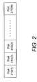
- FIG. 2 shows a switch 120 , in accordance with one embodiment.
- Switch 120 includes a plurality of ports 210 ( 1 ) to 210 (N), each of which connects a network device to a network.
- a port 210 connects service processor 110 via connection 115 to network 130 .
- Switch 120 via network 130 , may also route the data, usually in the form of packets, between devices.
- the device and switch 120 experience a negotiation process to determine the speed and/or the duplex at which the device operates in the network.
- switch 120 supports two networks of two speeds 10Base-T and 100Base-T.
- Switch 120 uses the data speed to assign a device, e.g., service processor 110 , to either the 10Base-T or the 100Base-T network. For example, if service processor 110 is to operate at the 10Base-T speed, then switch 120 assigns service processor 110 to the 10Base-T network. Similarly, if service processor 110 is to operate at the 100Base-T speed, then switch 120 assigns service processor 110 to the 100Base-T network. In one embodiment, once being assigned to a particular network of a particular speed, service processor 110 can only communicate with devices in the same network, but is not allowed to communicate with devices in a different network.
- Switch 120 sets the network speed that can be supported by both service processor 110 and switch 120 .
- switch 120 can support all speeds supported by service processor 110 .
- switch 120 includes an auto-negotiate option that sets the highest speed advertised by service processor 110 . As a result, if service processor 110 advertises that it can support up to 100Base-T, then switch 120 sets the speed to 100Base-T. Similarly, if service processor 110 advertises that it can support up to 1000Base-T, then switch 120 sets the speed to 1000Base-T, etc.
- Switch 120 uses the speed desired by service processor 110 when switch 120 is in a forced mode, i.e., switch 120 cannot invoke the auto-negotiate process. For example, if service processor 110 desires a 10Base-T or a 100Base-T, then switch 120 sets the speed to 10Base-T or 100Base-T, respectively. In one embodiment, when in the forced mode, switch 120 does not detect the duplex and defaults to half duplex. In an alternative embodiment, switch 120 may be configured to match the duplex set by service processor 110 . Consequently, if service processor 110 desires a half duplex or a full duplex, then switch 120 can be configured to half duplex or full duplex, respectively.
- Switch 120 is used as an example, other network controllers that connect a device to a network such as a wireless LAN switch is within the scope of the invention.
- FIG. 3 is a flowchart illustrating a method for configuring parameters for a device, e.g., service processor 110 , to be connected to network 130 .
- step 304 a user, via the control panel and the user interface of service processor 110 , enters a command to configure the network parameters for service processor 110 .
- step 308 from the choices provided from the user interface, the user enters the desired value for the parameter, e.g., 10Base-T, 100Base-T, full duplex, half duplex, non-negotiate, auto negotiate, etc.
- the user selects, non-negotiate, 10Base-T, and full duplex, and it is assumed that the values received from the user are different from those stored in the bootline of service processor 110 .
- step 312 service processor 110 updates the values stored in the bootline with the entered values.
- service processor 110 stops the network and writes appropriate values to appropriate registers, e.g., 10Base-T to the speed register, full duplex to the duplex register, etc.
- step 320 service processor 110 restarts the network with the network registers having the new parameter values.
- step 326 based on the new parameter values set in the appropriate registers, switch 120 via connection 115 and other hardware mechanism, determines whether service processor 110 desires a non-negotiate mode or an auto-negotiate mode.
- switch 120 based on the detected speed, assigns service processor 110 to the desired network, which, for illustration purposes, is a 10Base-T network.
- the desired network which, for illustration purposes, is a 10Base-T network.
- switch 120 in step 332 , sets to a default, e.g., of half duplex.
- a user manually sets the duplex to a value provided in step 308 .
- switch 120 may automatically set this value.
- step 334 service processor 110 freely communicates with other devices in the assigned 10Base-T network.
- step 326 service processor 110 desires the auto-negotiate mode
- switch 120 in step 340 , sets the speed to a highest speed supported by both service processor 110 and switch 120 .
- switch 120 in conjunction with the auto-negotiate mode that sets to the highest speed, also sets to the highest duplex supported by both service processor 110 and switch 120 .
- switch 120 sets the duplex to a value provided in step 308 , and, in step 334 , service processor 110 is free to communicate with devices to the assigned network.
- the user had choices to configure network parameters for service processor 110 , which is advantageous over other approaches.
- the user can control which network and/or which duplex for a device, e.g., service processor 110 , to operate. This is greatly useful when switch 120 does not allow for setting the network parameters.
- switch 120 forces service processor 110 to 10Base-T and half duplex.
- service processor 110 was set to operate at desired values, e.g., 10Base-T and full duplex, instead of half duplex.
- service processor 110 may be configured to, and thus tested with, various combinations of parameter, e.g., auto-negotiate, speed, duplex, etc.
- FIG. 4 is a block diagram showing a computer system 400 upon which embodiments of the invention may be implemented.
- computer system 400 may be implemented to operate as a system 100 , to perform functions in accordance with the techniques described above, etc.
- computer system 400 includes a central processing unit (CPU) 404 , random access memories (RAMs) 408 , read-only memories (ROMs) 412 , a storage device 416 , and a communication interface 420 , all of which are connected to a bus 424 .
- CPU central processing unit
- RAMs random access memories
- ROMs read-only memories
- CPU 404 controls logic, processes information, and coordinates activities within computer system 400 .
- CPU 404 executes instructions stored in RAMs 408 and ROMs 412 , by, for example, coordinating the movement of data from input device 428 to display device 432 .
- CPU 404 may include one or a plurality of processors.
- RAMs 408 temporarily store information and instructions to be executed by CPU 404 .
- Information in RAMs 408 may be obtained from input device 428 or generated by CPU 404 as part of the algorithmic processes required by the instructions that are executed by CPU 404 .
- ROMs 412 store information and instructions that, once written in a ROM chip, are read-only and are not modified or removed. In one embodiment, ROMs 412 store commands for configurations and initial operations of computer system 400 .
- Storage device 416 such as floppy disks, disk drives, or tape drives, durably stores information for use by computer system 400 .
- Communication interface 420 enables computer system 400 to interface with other computers or devices.
- Communication interface 420 may be, for example, a modem, an integrated services digital network (ISDN) card, a local area network (LAN) port, etc.
- ISDN integrated services digital network
- LAN local area network
- modems or ISDN cards provide data communications via telephone lines while a LAN port provides data communications via a LAN.
- Communication interface 420 may also allow wireless communications.
- Bus 424 can be any communication mechanism for communicating information for use by computer system 400 .
- bus 424 is a media for transferring data between CPU 404 , RAMs 408 , ROMs 412 , storage device 416 , communication interface 420 , etc.
- Computer system 400 is typically coupled to an input device 428 , a display device 432 , and a cursor control 436 .
- Input device 428 such as a keyboard including alphanumeric and other keys, communicates information and commands to CPU 404 .
- Display device 432 such as a cathode ray tube (CRT), displays information to users of computer system 400 .
- Cursor control 436 such as a mouse, a trackball, or cursor direction keys, communicates direction information and commands to CPU 404 and controls cursor movement on display device 432 .
- Computer system 400 may communicate with other computers or devices through one or more networks. For example, computer system 400 , using communication interface 420 , communicates through a network 440 to another computer 444 connected to a printer 448 , or through the world wide web 452 to a server 456 .
- the world wide web 452 is commonly referred to as the “Internet.”
- computer system 400 may access the Internet 452 via network 440 .
- Computer system 400 may be used to implement the techniques described above.
- CPU 404 performs the steps of the techniques by executing instructions brought to RAMs 408 .
- hard-wired circuitry may be used in place of or in combination with software instructions to implement the described techniques. Consequently, embodiments of the invention are not limited to any one or a combination of software, firmware, hardware, or circuitry.
- Computer-readable media may be, for example, a floppy disk, a hard disk, a zip-drive cartridge, a magnetic tape, or any other magnetic medium, a CD-ROM, a CD-RAM, a DVD-ROM, a DVD-RAM, or any other optical medium, paper-tape, punch-cards, or any other physical medium having patterns of holes, a RAM, a ROM, an EPROM, or any other memory chip or cartridge.
- Computer-readable media may also be coaxial cables, copper wire, fiber optics, acoustic or electromagnetic waves, capacitive or inductive coupling, etc.
- the instructions to be executed by CPU 404 are in the form of one or more software programs and are initially stored in a CD-ROM being interfaced with computer system 400 via bus 424 .
- Computer system 400 loads these instructions in RAMs 408 , executes some instructions, and sends some instructions via communication interface 420 , a modem, and a telephone line to a network, e.g. network 440 , the Internet 452 , etc.
- a remote computer receiving data through a network cable, executes the received instructions and sends the data to computer system 400 to be stored in storage device 416 .
Abstract
Description
Claims (16)
Priority Applications (1)
| Application Number | Priority Date | Filing Date | Title |
|---|---|---|---|
| US10/163,290 US7281056B1 (en) | 2002-06-04 | 2002-06-04 | Assigning a device to a network |
Applications Claiming Priority (1)
| Application Number | Priority Date | Filing Date | Title |
|---|---|---|---|
| US10/163,290 US7281056B1 (en) | 2002-06-04 | 2002-06-04 | Assigning a device to a network |
Publications (1)
| Publication Number | Publication Date |
|---|---|
| US7281056B1 true US7281056B1 (en) | 2007-10-09 |
Family
ID=38562242
Family Applications (1)
| Application Number | Title | Priority Date | Filing Date |
|---|---|---|---|
| US10/163,290 Expired - Lifetime US7281056B1 (en) | 2002-06-04 | 2002-06-04 | Assigning a device to a network |
Country Status (1)
| Country | Link |
|---|---|
| US (1) | US7281056B1 (en) |
Cited By (4)
| Publication number | Priority date | Publication date | Assignee | Title |
|---|---|---|---|---|
| US20060136706A1 (en) * | 2004-12-22 | 2006-06-22 | Montgomery Michael S | Product configuration during boot process |
| US20080005552A1 (en) * | 2006-06-13 | 2008-01-03 | Distefano John R | Safety Data Writes |
| JP2011044955A (en) * | 2009-08-21 | 2011-03-03 | Fujitsu Ltd | Setting change method by network manager equipment and program, control method and program of network equipment, network manager equipment, and network equipment |
| US8667105B1 (en) * | 2002-06-26 | 2014-03-04 | Apple Inc. | Systems and methods facilitating relocatability of devices between networks |
Citations (8)
| Publication number | Priority date | Publication date | Assignee | Title |
|---|---|---|---|---|
| US6335935B2 (en) * | 1998-07-08 | 2002-01-01 | Broadcom Corporation | Network switching architecture with fast filtering processor |
| US6553232B1 (en) * | 1997-01-03 | 2003-04-22 | Siemens Information & Communication Networks, Inc. | System and method for calendar-based cellular smart switching |
| US6629145B1 (en) * | 2000-03-01 | 2003-09-30 | Avaya Technology Corp. | System and method of network independent remote configuration of internet server appliance |
| US6658010B1 (en) * | 1996-07-25 | 2003-12-02 | Hybrid Networks, Inc. | High-speed internet access system |
| US6813268B1 (en) * | 1999-05-21 | 2004-11-02 | Broadcom Corporation | Stacked network switch configuration |
| US6813648B1 (en) * | 2001-07-02 | 2004-11-02 | Adaptec, Inc. | Method and apparatus for post boot-up domain validation |
| US6859825B1 (en) * | 1999-12-29 | 2005-02-22 | Advanced Micro Devices, Inc. | System and method enabling configuration of physical layer devices and corresponding link partners for communicating network data via a configuration source or auto-negotiation |
| US6901580B2 (en) * | 2001-06-22 | 2005-05-31 | Intel Corporation | Configuration parameter sequencing and sequencer |
-
2002
- 2002-06-04 US US10/163,290 patent/US7281056B1/en not_active Expired - Lifetime
Patent Citations (8)
| Publication number | Priority date | Publication date | Assignee | Title |
|---|---|---|---|---|
| US6658010B1 (en) * | 1996-07-25 | 2003-12-02 | Hybrid Networks, Inc. | High-speed internet access system |
| US6553232B1 (en) * | 1997-01-03 | 2003-04-22 | Siemens Information & Communication Networks, Inc. | System and method for calendar-based cellular smart switching |
| US6335935B2 (en) * | 1998-07-08 | 2002-01-01 | Broadcom Corporation | Network switching architecture with fast filtering processor |
| US6813268B1 (en) * | 1999-05-21 | 2004-11-02 | Broadcom Corporation | Stacked network switch configuration |
| US6859825B1 (en) * | 1999-12-29 | 2005-02-22 | Advanced Micro Devices, Inc. | System and method enabling configuration of physical layer devices and corresponding link partners for communicating network data via a configuration source or auto-negotiation |
| US6629145B1 (en) * | 2000-03-01 | 2003-09-30 | Avaya Technology Corp. | System and method of network independent remote configuration of internet server appliance |
| US6901580B2 (en) * | 2001-06-22 | 2005-05-31 | Intel Corporation | Configuration parameter sequencing and sequencer |
| US6813648B1 (en) * | 2001-07-02 | 2004-11-02 | Adaptec, Inc. | Method and apparatus for post boot-up domain validation |
Cited By (7)
| Publication number | Priority date | Publication date | Assignee | Title |
|---|---|---|---|---|
| US8667105B1 (en) * | 2002-06-26 | 2014-03-04 | Apple Inc. | Systems and methods facilitating relocatability of devices between networks |
| US8892715B2 (en) * | 2002-06-26 | 2014-11-18 | Apple Inc. | Systems and methods facilitating relocatability of devices between networks |
| US9832696B2 (en) | 2002-06-26 | 2017-11-28 | Apple Inc. | Systems and methods facilitating relocatability of devices between networks |
| US20060136706A1 (en) * | 2004-12-22 | 2006-06-22 | Montgomery Michael S | Product configuration during boot process |
| US20080005552A1 (en) * | 2006-06-13 | 2008-01-03 | Distefano John R | Safety Data Writes |
| US8380975B2 (en) * | 2006-06-13 | 2013-02-19 | Siemens Industry, Inc. | Safety data writes |
| JP2011044955A (en) * | 2009-08-21 | 2011-03-03 | Fujitsu Ltd | Setting change method by network manager equipment and program, control method and program of network equipment, network manager equipment, and network equipment |
Similar Documents
| Publication | Publication Date | Title |
|---|---|---|
| US7280547B2 (en) | Dynamic WAN port detection | |
| US6327613B1 (en) | Method and apparatus for sharing peripheral devices over a network | |
| TWI239160B (en) | Remote booting method and apparatus applied in WAN based on IP technique | |
| US8359384B2 (en) | Method, system, and apparatus for communicating with a computer management device | |
| US9398072B2 (en) | Virtual media systems, methods and devices | |
| US8015331B2 (en) | Multi-console workstations concurrently supporting multiple users | |
| US6314455B1 (en) | Data processing system and method for permitting a server to remotely initiate a client's boot block recovery | |
| US6704824B1 (en) | Universal serial bus adapter with automatic installation | |
| JP2683499B2 (en) | Communication of local area network-based applications over a switched network | |
| US8706839B2 (en) | Virtual serial port and protocol for use in serial-over-LAN communication | |
| US7234082B2 (en) | Apparatus of remote server console redirection | |
| CN101685431B (en) | Remote desktop control system using usb interface and method thereof | |
| US6918000B2 (en) | USB hub with soft select ports | |
| US20090089460A1 (en) | Storage device and storage device access control method | |
| US20030061320A1 (en) | Configuring a network parameter to a device | |
| US6959380B2 (en) | Seamless computer system remote control | |
| TWI467378B (en) | Method for selective suspension of network device | |
| JP2001117892A (en) | Multi-processor computer system for communication via internal bus and its communication method | |
| US6275851B1 (en) | Data processing system and method for remotely controlling modification of a client's initialization settings | |
| US20070155422A1 (en) | Method for controlling mobile data connection through USB Ethernet management of mobile station | |
| US7464133B1 (en) | Server/client system | |
| US7281056B1 (en) | Assigning a device to a network | |
| US9087031B2 (en) | Method and program for selective suspension of USB device | |
| US20030065864A1 (en) | System and method supporting remote data processing system management | |
| US6173321B1 (en) | Using a systems network architecture logical unit activation request unit as a dynamic configuration definition in a gateway |
Legal Events
| Date | Code | Title | Description |
|---|---|---|---|
| AS | Assignment |
Owner name: HEWLETT-PACKARD COMPANY, COLORADO Free format text: ASSIGNMENT OF ASSIGNORS INTEREST;ASSIGNORS:NOLAN, JOHN;DUISENBERG, KENNETH C.;REEL/FRAME:013152/0572 Effective date: 20020531 |
|
| AS | Assignment |
Owner name: HEWLETT-PACKARD DEVELOPMENT COMPANY, L.P., COLORAD Free format text: ASSIGNMENT OF ASSIGNORS INTEREST;ASSIGNOR:HEWLETT-PACKARD COMPANY;REEL/FRAME:013776/0928A Effective date: 20030131 Owner name: HEWLETT-PACKARD DEVELOPMENT COMPANY, L.P.,COLORADO Free format text: ASSIGNMENT OF ASSIGNORS INTEREST;ASSIGNOR:HEWLETT-PACKARD COMPANY;REEL/FRAME:013776/0928 Effective date: 20030131 Owner name: HEWLETT-PACKARD DEVELOPMENT COMPANY, L.P., COLORAD Free format text: ASSIGNMENT OF ASSIGNORS INTEREST;ASSIGNOR:HEWLETT-PACKARD COMPANY;REEL/FRAME:013776/0928 Effective date: 20030131 |
|
| STCF | Information on status: patent grant |
Free format text: PATENTED CASE |
|
| CC | Certificate of correction | ||
| FPAY | Fee payment |
Year of fee payment: 4 |
|
| FPAY | Fee payment |
Year of fee payment: 8 |
|
| AS | Assignment |
Owner name: HEWLETT PACKARD ENTERPRISE DEVELOPMENT LP, TEXAS Free format text: ASSIGNMENT OF ASSIGNORS INTEREST;ASSIGNOR:HEWLETT-PACKARD DEVELOPMENT COMPANY, L.P.;REEL/FRAME:037079/0001 Effective date: 20151027 |
|
| MAFP | Maintenance fee payment |
Free format text: PAYMENT OF MAINTENANCE FEE, 12TH YEAR, LARGE ENTITY (ORIGINAL EVENT CODE: M1553); ENTITY STATUS OF PATENT OWNER: LARGE ENTITY Year of fee payment: 12 |