US7286552B1 - Method and apparatus for providing quality of service across a switched backplane for multicast packets - Google Patents
Method and apparatus for providing quality of service across a switched backplane for multicast packets Download PDFInfo
- Publication number
- US7286552B1 US7286552B1 US10/205,822 US20582202A US7286552B1 US 7286552 B1 US7286552 B1 US 7286552B1 US 20582202 A US20582202 A US 20582202A US 7286552 B1 US7286552 B1 US 7286552B1
- Authority
- US
- United States
- Prior art keywords
- queue
- egress
- congested
- backplane
- egress queue
- Prior art date
- Legal status (The legal status is an assumption and is not a legal conclusion. Google has not performed a legal analysis and makes no representation as to the accuracy of the status listed.)
- Active, expires
Links
Images


Classifications
-
- H—ELECTRICITY
- H04—ELECTRIC COMMUNICATION TECHNIQUE
- H04L—TRANSMISSION OF DIGITAL INFORMATION, e.g. TELEGRAPHIC COMMUNICATION
- H04L47/00—Traffic control in data switching networks
- H04L47/10—Flow control; Congestion control
- H04L47/30—Flow control; Congestion control in combination with information about buffer occupancy at either end or at transit nodes
-
- H—ELECTRICITY
- H04—ELECTRIC COMMUNICATION TECHNIQUE
- H04L—TRANSMISSION OF DIGITAL INFORMATION, e.g. TELEGRAPHIC COMMUNICATION
- H04L12/00—Data switching networks
- H04L12/02—Details
- H04L12/16—Arrangements for providing special services to substations
- H04L12/18—Arrangements for providing special services to substations for broadcast or conference, e.g. multicast
- H04L12/1881—Arrangements for providing special services to substations for broadcast or conference, e.g. multicast with schedule organisation, e.g. priority, sequence management
-
- H—ELECTRICITY
- H04—ELECTRIC COMMUNICATION TECHNIQUE
- H04L—TRANSMISSION OF DIGITAL INFORMATION, e.g. TELEGRAPHIC COMMUNICATION
- H04L47/00—Traffic control in data switching networks
- H04L47/10—Flow control; Congestion control
-
- H—ELECTRICITY
- H04—ELECTRIC COMMUNICATION TECHNIQUE
- H04L—TRANSMISSION OF DIGITAL INFORMATION, e.g. TELEGRAPHIC COMMUNICATION
- H04L49/00—Packet switching elements
- H04L49/20—Support for services
- H04L49/201—Multicast operation; Broadcast operation
-
- H—ELECTRICITY
- H04—ELECTRIC COMMUNICATION TECHNIQUE
- H04L—TRANSMISSION OF DIGITAL INFORMATION, e.g. TELEGRAPHIC COMMUNICATION
- H04L49/00—Packet switching elements
- H04L49/50—Overload detection or protection within a single switching element
- H04L49/505—Corrective measures
-
- H—ELECTRICITY
- H04—ELECTRIC COMMUNICATION TECHNIQUE
- H04L—TRANSMISSION OF DIGITAL INFORMATION, e.g. TELEGRAPHIC COMMUNICATION
- H04L49/00—Packet switching elements
- H04L49/10—Packet switching elements characterised by the switching fabric construction
- H04L49/101—Packet switching elements characterised by the switching fabric construction using crossbar or matrix
Definitions
- the present invention relates to the field of computer networks and internetworking communications technologies.
- the present invention relates to providing quality of service in a network.
- QoS Quality of service
- VOI voice over internet
- a high-performance Internet router typically comprises a plurality of input/output cards (“blades” herein) that receive, buffer, and transmit data packets.
- blades input/output cards
- a central switched backplane also referred to as a crossbar switch
- multiple blades can communicate with each other simultaneously, enabling data packets to be sent from one blade to another across “backplane channels.”
- ingress queues receive the packets from other devices on the network
- egress queues transmitting the packets to other devices
- the ingress and egress queues are mapped to one another so that one or more of the ingress queues feed into one or more of the egress queues.
- the ingress queues may be capable of handling packets at a faster rate than the egress queues.
- the resulting congestion is typically localized at one or more of the egress queues on one of the blades, while the source of the congestion may be any of the ingress queues on the same blade or on one or more of the other blades.
- Conflicts can arise if more than one ingress queue wants to send a data packet to the same egress queue at the same time, or if the rate at which the ingress queue is sending packets exceeds the rate at which the egress queue can receive packets.
- FIG. 1 illustrates an example scenario of multiple ingress queues mapped to one egress queue and unfair dropping of packets from the ingress queues due to congestion.
- three ingress queues 110 with minimum sending rates of 5, 7, and 8 megabits per second (Mbps), respectively, are mapped to an egress queue that can only service a maximum of 20 Mbps.
- Mbps megabits per second
- TDM time-division multiplex
- the channel's available sending time is divided into intervals, where the first ingress queue sends its packets during the first interval, the second ingress queue sends its packets during the second interval, and the third ingress queue sends its packets during the third interval, and so forth.
- the TDM scheme is inefficient, as some intervals are wasted when held open even though the corresponding ingress queue has no packet to send.
- An alternative scheme to avoid dropping packets is to buffer the excess packets in the queues until there is an opportunity to send them without risk of being dropped, i.e., after the congestion has subsided and the channels are open.
- buffering the packets requires memory and memory is expensive.
- Yet another alternative is to use a backpressure mechanism, where the egress queue experiencing the congestion sends feedback to the ingress queue to reduce the rate at which it is sending packets.
- the backpressure mechanism works well when deployed in a single chip. However, when the egress queues and ingress queues reside on different blades within the router, or even on different chips within the blade, the ability to timely communicate the feedback to the ingress queue is reduced.
- the backpressure mechanism can result in an undesirable head-of-the-line blocking scenario.
- the head-of-the-line blocking scenario occurs when only one or some of the egress queues is congested, but the feedback to the single ingress queue causes all of the aggregated traffic to slow down, even traffic destined for the uncongested egress queues.
- a similar undesirable head-of-the-line blocking scenario occurs for multicast traffic, where the multicast traffic to all of the egress queues is slowed down, even though only one or some of the egress queues receiving the multicast traffic are experiencing congestion.
- a method is provided in which quality of service is enabled across a switched backplane using a messaging system.
- each blade in a router having a switched backplane is provided with one or more ingress queues buffering incoming traffic, one or more egress queues buffering outgoing traffic, and a queue manager.
- the egress queues include outer queues and backplane queues. Traffic on an outer queue is destined for another router, whereas traffic on a backplane queue is destined for another blade in the same router.
- the queue manager includes an ingress queue manager and an egress queue manager which each manage the traffic on their respective queues in accordance with the messaging system.
- the messaging system includes a congestion message and a resume message.
- the egress queue manager generates a congestion message when the traffic in an egress queue exceeds an upper queue threshold, and a resume message when the traffic in the congested egress queue falls below a lower queue threshold.
- the egress queue manager uses a queue timer in conjunction with the queue thresholds to repeat the generation of the congestion and resume messages to increase the robustness of the messaging system.
- the queue manager When an egress queue timer expires, the queue manager generates a congestion or resume message in accordance with the queue threshold.
- the congestion messages are propagated to the ingress queue manager on the local blade.
- the congestion message causes the ingress queue manager to reduce the rate at which packets are dequeued from the ingress queues that may be responsible for the congestion.
- the ingress queues that may be responsible for the congestion are those ingress queues mapped to the destination ports associated with the congested queue.
- the ingress queue manager reduces the rate at which packets are dequeued to no lower than the committed information rate for the router.
- the congestion message when the congested queue is a backplane queue, the congestion message causes the ingress queue manager to reduce the rate at which packets are dequeued from any ingress queue mapped to any port on the destination blade associated with the congested backplane queue.
- the congestion messages are propagated to the egress queue managers on each of the other blades in the router.
- An egress queue manager that receives a message from another blade further propagates the message to the ingress queue manager on its own blade, where the message causes the ingress queue manager to reduce the rate at which packets are dequeued from any of the ingress queues on that blade that may also be responsible for the congestion.
- the egress queue manager reduces the rate at which packets are enqueued to the backplane port mapped to congested backplane queue.
- each blade is further provided with congestion flags that indicate which of the backplane queues is congested both on the local blade and on the destination blades.
- the egress queue manager uses the congestion flags in conjunction with the queue thresholds and queue timers to aid in determining when to generate the resume messages to cause the ingress and egress queue managers to resume normal packet rates for the previously slowed ingress queues and backplane ports.
- the egress queue manager when a previously congested egress queue falls below the lower queue threshold, the egress queue manager generates a resume message and clears the congestion flag associated with the previously congested queue. Similarly to the congestion messages, the resume message is propagated to the ingress queue manager and to the egress queue managers on the other blades. However, when the egress queue in question is a backplane queue, the egress queue manager delays generating a resume message and clearing the congestion flag until the congestion flags indicate that all of the other egress queues mapped to the same destination blade are also not congested. In addition, the egress queue manager further delays resuming normal packet rates until the congestion flags indicate that all of the egress queues on other blades mapped to the same destination blade are also not congested.
- each blade is further provided with ingress queue flags which indicate which ingress queues are operating at reduced packet rates.
- the resume message causes the ingress queue manager to resume the normal packet rates for all ingress queues mapped to the backplane ports associated with the backplane queue.
- the resume message causes the ingress queue manager to resume the normal packet rates for all ingress queues mapped to the outer ports associated with the outer queue, but only after the ingress queue flags indicate that all of the other ingress queues mapped to those same outer ports have also resumed normal packet rates. This insures that the normal quality of service is not resumed prematurely, i.e., when other egress queues serving those same outer ports are still congested.
- the ingress queues may be designated as unicast queues or multicast queues.
- enabling quality of service through congestion control is managed by the egress queue managers in accordance with multicast scheduling flags.
- a multicast scheduling flag is associated with each egress queue capable of receiving a packet from a multicast queue.
- the egress queue manager refrains from enqueueing any marked multicast packets to the destination ports associated with the congested outer queue until the congestion subsides.
- the congested egress queue is a backplane queue
- the egress queue manager refrains from enqueuing any marked multicast packets to the destination ports on the destination blade associated with the congested backplane queue until the congestion subsides.
- FIG. 1 illustrates an example scenario of multiple ingress queues mapped to one egress queues and unfair dropping of packets from the ingress queues due to congestion;
- FIG. 2 is a block diagram illustrating a packet forwarding device incorporating a method and apparatus for enabling quality of service in accordance with one embodiment of the invention, and the operating environment in which certain aspects of the invention may be practiced;
- FIG. 3 is a block diagram illustrating certain additional aspects of the embodiment of the invention illustrated FIG. 2 ;
- FIGS. 4A-4D illustrate examples of queue mapping that may be employed using an embodiment of the invention illustrated in FIGS. 2-3 ;
- FIG. 5 illustrates the example scenario in FIG. 1 , in which certain aspects of a messaging system enabling quality of service may be practiced in accordance with one embodiment of the invention illustrated in FIGS. 2-3 ;
- FIG. 6 further illustrates the example scenario in FIGS. 1 and 5 , in which certain aspects of a messaging system enabling quality of service may be practiced in accordance with one embodiment of the invention illustrated in FIGS. 2-3 ;
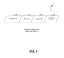
- FIG. 7 illustrates the a format of the congestion and resume messages in accordance with one embodiment of the invention illustrated FIGS. 2-6 ;
- FIGS. 8-15 are flow diagrams illustrating certain aspects of a method to be performed by a packet forwarding device incorporating a messaging system enabling quality of service in accordance with one embodiment of the invention illustrated in FIGS. 2-7 ;
- FIG. 16 illustrates one embodiment of a suitable computing environment in which certain aspects of the invention illustrated in FIGS. 2-15 may be practiced.
- FIG. 2 is a block diagram illustrating a generalized embodiment of a packet forwarding device incorporating a method and apparatus for enabling quality of service in accordance with one embodiment of the invention, and the operating environment in which certain aspects of the invention may be practiced.
- the packet forwarding device 100 is typically a high-performance Internet router providing layer-3 internetwork packet forwarding services for hosts connected to the Internet via a local area network (LAN).
- the router 100 may be comprised of several blades 102 connected to one another using a crossbar 104 , also referred to as a switched backplane.
- the router 100 is shown with four blades 102 , each comprising an egress queue manager 106 , an ingress queue manager 108 , each of which manage thousands of egress queues 112 and ingress queues 110 respectively, using egress queue flags 114 and ingress queue flags 116 .
- the egress queues 112 and ingress queues 110 are respectively connected to numerous ports 118 and 120 , which serve as the router's physical link to the rest of the network.
- a typical router 100 may have up to 16 such blades, each having a combined aggregate rate of 80 gigabits per second (Gbps). Of the 80 Gbps throughput per blade, 40 Gbps may be used to connect the blade to the backplane 104 , and the remaining 40 Gbps may be used to connect the blade to the rest of the network, depending on the needs of the particular applications that the router 100 is supporting. In one embodiment, each blade supports 8 output channels and a central processing unit CPU channel at 10 Gbps.
- FIG. 3 is a block diagram illustrating certain additional aspects of the embodiment of the invention illustrated FIG. 2 .
- the egress queue manager 106 and ingress queue manager 108 together with the queue thresholds 122 , queue timers 123 , egress queue flags 114 , ingress queue flags 116 , and messages 124 comprise a messaging system 101 to enable quality of service on router 100 having a switched backplane 104 , ingress queues 110 , egress queues 112 and ports 118 , 120 , and associated other components.
- the egress queues 112 comprise outer queues 112 A that are connected to outer ports 118 A, which connect the router to the rest of the network, and backplane queues 112 B that are connected to backplane ports 118 B, which connect the blade 102 to the backplane 104 and the other blades 102 in the router 100 using backplane subchannels 2 and 4 ( 128 ) ( 130 ).
- backplane queues 112 B that are connected to backplane ports 118 B, which connect the blade 102 to the backplane 104 and the other blades 102 in the router 100 using backplane subchannels 2 and 4 ( 128 ) ( 130 ).
- backplane queues 112 that are connected to outer ports 118 A, which connect the router to the rest of the network
- backplane queues 112 B that are connected to backplane ports 118 B, which connect the blade 102 to the backplane 104 and the other blades 102 in the router 100 using backplane subchannels 2 and 4 ( 128
- the egress queue manager 106 operates in conjunction with the queue thresholds 122 and the egress queue flags 114 to manage all of the scheduling and queuing of data packets to the outer ports 118 A and the backplane ports 118 B.
- the ingress queue manager 108 operates in conjunction with the ingress queue flags 116 and feedback from the egress queue manager 106 in the form of messages 124 to manage all of the scheduling and queueing of data packets in the ingress queues 110 .
- the queue thresholds 122 comprise values that indicate the upper and lower queue sizes, and may be configured to suit the needs of the network applications which the router 100 is supporting.
- the egress queue manager 106 When an egress queue 112 exceeds the upper queue threshold, the egress queue manager 106 generates congestion messages 124 to the ingress queue manager 108 to cause the ingress queues 110 responsible for causing the congestion to slow down the rates at which packets are dequeued to the congested egress queues 112 .
- the egress queue manager 106 sends the congestion messages 124 across the backplane to the other blades on the router 100 to cause the egress and ingress queue managers on those blades to take similar actions to cause the ingress queues responsible for causing the congestion to the backplane queue 112 B to slow down their packet rates.
- the congestion messages 124 are sent to the other blades using a separate control backplane (not shown) instead of the same backplane used by the data packets.
- the egress queue manager 106 further slows down the dequeuing of packets from the congested backplane queue 112 B, as well as from any other egress queue mapped to the same backplane port to which the congested backplane queue is mapped. In this way, the congestion is quickly brought under control, and the quality of service is enabled across the backplane switch 104 .
- the egress queue manager 106 determines that the egress queue 112 is no longer congested and generates resume messages 124 to the ingress queue manager 108 to resume normal packet rates on the ingress queues 110 whose rates were previously reduced in accordance with the values of the ingress queue flags 116 .
- the ingress queue flags 116 comprise stored values that indicate the state of congestion of outer egress queues 112 A. Specifically, since an ingress queue 110 may be mapped to many outer queues 112 A on the blade, the ingress queue flags 124 represent the state of congestion of all outer queues 112 A to which a particular ingress queue 110 is mapped.
- the ingress queue flags 126 for that ingress queue 110 comprise eight values, one for each mapped outer queue 112 A.
- the reduced packet rates on that ingress queue 110 are maintained. But when all of the values indicate that the mapped outer queues are no longer congested, then normal packet rates are resumed.
- the ingress queue flags 126 may be implemented as a bitmask, where each bit in the mask represents one ingress queue. It is understood by one of ordinary skill in the art that the ingress queue flags 126 may be implemented as a table or a database or other type of repository without departing from the scope of the present invention.
- the egress queue manager 106 resumes the normal rate of dequeuing packets from the previously congested queue in accordance with the values of the egress queue flags 114 .
- the egress queue flags 114 comprise stored values that indicate the state of congestion of the backplane queues 112 B on both the local and the other blades 102 .
- the egress queue flags 124 may be implemented as a bitmask. For example, in a router 100 having 16 blades, the bitmask comprises 16 bits, with one bit for each of the blades 102 .
- the fourth egress queue flag representing the state of backplane congestion to Blade 4
- the fourth egress queue flag may have a 1 in the 5 th and 9 th bits, and zeroes in the 2 nd and remaining bits.
- the bit values indicate that even though the local backplane queues on Blade 2 destined for Blade 4 are not congested, Blade 4 is nevertheless considered to be congested since the local egress queue manager 106 has received congestion notifications from the egress queue managers 106 on Blades 5 and 9 , indicating that their backplane queues destined for Blade 4 are congested.
- the local egress queue manager 106 resumes normal dequeuing of packets from the local backplane queues destined for Blade 4 only after all of the backplane queues of other blades destined for Blade 4 are also not congested. It is understood by one of ordinary skill in the art that the egress queue flags 124 may be implemented as a table or a database or other type of repository without departing from the scope of the present invention.
- the messaging system 101 provides for the possibility of lost messages 124 due to signal degradation or various other reasons. Lost messages can cause problems with unfairness, since the messaging system 101 might cause a reduction in the rate of dequeueing packets from some ingress and egress queues and not others.
- the egress queue manager 106 that generated the congestion message reduces the normal rate of dequeuing packets from the congested backplane queue, but some or all of the other egress queue managers on the other blades will not take similar action since they missed the message. Should this situation persist, then the local backplane queues managed by the egress queue manager 106 that generated the congestion message will be at a disadvantage.
- the messaging system 101 is already resilient to losses in messages related to backplane queues 112 B.
- the traffic for the subchannel to the destination blade causing the congestion e.g. Blade 4
- the traffic for the subchannel to the destination blade causing the congestion is exceeding its capacity, then eventually some other backplane queue on another blade will become congested, and the egress queue manager on that blade will send a new congestion message to all of the other blades. Assuming the new congestion message is not lost, then the situation will resolve on its own.
- the backplane queues whose packet rates were reduced will empty, including the backplane queue that originally caused the first congestion message to be generated, and normal operations will resume.
- the messaging system 101 further employs a queue timer 123 in conjunction with the queue thresholds 122 to trigger the generation of additional congestion and resume messages 124 at pre-determined intervals.
- the queue timer 123 for a particular egress queue 112 expires, the egress queue manager 106 will test the egress queue 112 for congestion in accordance with the queue thresholds 122 .
- the queue timer 123 is a very long cyclic timer that has each of the egress queues 112 positioned at a fixed slot, staggered across the entire clock duration. Every time the queue timer 123 reaches the appropriate trigger time for a particular egress queue 112 , the egress queue manager 106 will generate a message 124 for the particular egress queue 112 . When the queue 112 is still congested (i.e., the queue exceeds the queue threshold), then the egress queue manager 106 generates a congestion message; otherwise the egress queue manager 106 will generate a resume message.
- the above-described timeout mechanism may be employed on the outer queues 112 A, or the backplane queues 112 B, or both.
- the queue timer 123 may be employed to safeguard the reliability of messages 124 to the local ingress queue manager 108 on the same blade or across the backplane 104 to other egress queue managers 106 on other blades, the latter being more susceptible to loss than the former.
- the repeated generation of messages 124 to avoid problems with lost messages may introduce additional queuing problems with the messages 124 themselves, particularly when the messages 124 are destined for egress queue managers 106 on other blades and must traverse the backplane 104 or another separate control backplane reserved for the messages 124 .
- the messaging system 101 further prioritizes the messages 124 , with the congestion messages having a higher priority than the resume messages, and the queue length derived messages (i.e., those messages generated solely due to the egress queue exceeding or falling below the queue threshold 122 ) having a higher priority than the queue timer derived messages (i.e., those messages generated after the queue timer expired).
- the message system 101 further prioritizes the messages 124 , with the messages associated with backplane congestion on the backplane queues 112 B having a higher priority than those associated with congestion on the outer queues 112 A.
- Table 1 illustrates an example of the priority ranking of the messages 124 that may occur in messaging system 101 . It should be understood by one of ordinary skill in the art that other prioritization of the messages 124 may be employed without departing from the scope of the invention.
- a router 100 having 16 blades there may be 8 backplane queues 112 B for each of the 16 subchannels for each of 8 output channels, in addition to 128 outer queues 112 A, resulting in a total of 1152 egress queues 112 . It is understood by one of ordinary skill in the art, other numbers of egress queues 112 may be employed without departing from the scope of the present invention.
- the ingress queues 110 comprise unicast queues 110 A and multicast queues 110 B, which connect the blade 102 to the input ports 120 that receive the data packets from other devices on the network.
- the unicast queues 110 A handle unicast data packets that are sent to a single destination, whereas the multicast queues 110 B handle multicast packets that are sent to multiple destinations.
- each blade may support up to 4000 ingress queues 110 , each having a minimum and maximum bandwidth rate for each egress queue 1112 to which they are mapped. It is understood by one of ordinary skill in the art that other numbers of ingress queues 110 may be employed without departing from the scope of the present invention.
- FIGS. 4A-4D illustrate examples of queue mapping that may be employed using an embodiment of the invention illustrated in FIGS. 2-3 .
- Queue mapping is a significant aspect of enabling quality of service since a typical router may have more ingress queues than egress queues. Even if the number of egress queues exceeds the number of ingress queues, the egress queues are often equipped with much less buffer storage than the ingress queues. Thus, depending on the router, it may be preferable to exploit the buffering in the ingress queues 110 rather than risk exceeding the buffering in the egress queues 112 .
- FIG. 4C illustrates a one-to-many mapping 43 .
- an ingress queue 110 may be mapped to several outer queues 112 A.
- One-to-many mapping arises when the ingress rate is limited on a per-port basis and the incoming traffic of a port is aggregated into one or a few ingress queues.
- the quality of service controlled flows from a particular ingress queue may only be mapped to multiple egress queues when all of the egress queues in question are on the same output port. In this way, the unfair congestion control caused by a single ingress queue does not affect the traffic flows destined for other output ports.
- FIG. 4D illustrates the many-to-many mapping 44 , which is a combination of the one-to-many 43 and many-to-one 42 scenarios already described.
- the quality of service controlled flows from a particular ingress queue may only be mapped to multiple egress queues when all of the egress queues in question are on the same output port.
- FIG. 5 illustrates the example many-to-one mapping scenario described in FIGS. 1 and 4C , in which certain aspects of a messaging system 101 enabling quality of service may be practiced in accordance with one embodiment of the invention illustrated in FIGS. 2-3 .
- the messaging system 101 conveys to the ingress queues 110 the feedback, i.e., the messages 124 , generated by the egress queue manager 106 to reduce the rate at which the packets are dequeued from the responsible ingress queues 110 to the minimum rates designated for minimum quality of service on those queues.
- the ingress queue manager 110 reduces the rate no lower than the committed information rate for the router.
- FIG. 6 further illustrates the example scenario in FIGS. 1 , 4 C and 5 , in which certain aspects of a messaging system 101 enabling quality of service may be practiced in accordance with one embodiment of the invention illustrated in FIGS. 2-3 .
- the results of the feedback conveyed to the ingress queues 110 to slow down to the minimum rates reveals that only those ingress queues 110 responsible for the errant flows drop packets, and the egress queue 112 receiving the packets drops none.
- FIG. 7 illustrates the format of the congestion and resume messages 124 in accordance with one embodiment of the invention illustrated FIGS. 2-6 .
- Each message 124 comprises three different data fields that together uniquely identify one of the egress queues 112 in the router 100 .
- One data field is the blade identification 134 , the value of which is the number or other identifying information of the blade on which the egress queue resides.
- Another data field is the port identification 136 , the value of which is the number or other identifying information of the port to which the traffic flows on the egress queue 112 are destined.
- Yet another data field is the queue identification 138 , the value of which is the number or other identifying information of the egress queue 112 within the port and blade identified by blade identification 134 .
- queue number 1234 on Port 6 of Blade 2 can be uniquely distinguished from queue number 1234 on Port 7 of Blade 4 .
- a control data field 140 is further provided to indicate whether the message is a congestion message indicating that the egress queue size has exceeded the upper queue threshold, or a resume message indicating the egress queue size has fallen below the lower queue threshold. It should be noted that the order in which the data fields are illustrated is for convenience only, and may be otherwise ordered without departing from the scope of the present invention.
- FIGS. 8-14 the particular methods of the invention are described in terms of computer software with reference to a series of flowcharts.
- the methods to be performed by a computer constitute computer programs made up of computer-executable instructions. Describing the methods by reference to a flowchart enables one skilled in the art to develop such programs including such instructions to carry out the methods on suitably configured computers (the processor of the computer executing the instructions from computer-accessible media).
- the computer-executable instructions may be written in a computer programming language or may be embodied in firmware logic, or in hardware such as in an application specific integrated circuit (ASIC). If written in a programming language conforming to a recognized standard, such instructions can be executed on a variety of hardware platforms and for interface to a variety of operating systems.
- ASIC application specific integrated circuit
- egress queue ( 3 , 48 , 2 ) refers to queue Q 2 in port P 48 on blade B 3 .
- port P 48 is a backplane port mapped to subchannel 4
- the destination blade B′ for egress queue ( 3 , 48 , 2 ) is blade B′ 4 .
- the egress queue manager 106 further determines whether the port to which the traffic flows in the egress queue 112 are destined is a backplane port 118 B or an outer port 118 A.
- the egress queue 112 is a backplane queue 112 B. This implies that there is not enough bandwidth on the backplane 104 for the subchannel to the blade to which the backplane queue 112 B is destined (e.g. subchannel 4 to blade B′ 4 for port P 48 ).
- the egress queue manager 106 slows down the enqueuing of packets to the destination blade B′ to which the backplane queue 112 B is mapped to the minimum rate established for the quality of service policy for affected traffic flows.
- the egress queue manager 106 sends the congestion message 124 to all of the egress queue managers 106 on the other blades so that their egress queue managers 106 can take the same actions as the egress queue manager 106 on the local blade (see FIG. 9 for a description of the actions 200 B taken by the egress queue manager 106 upon receipt of the congestion message 124 ).
- FIG. 9 illustrates the actions 200 B taken by the egress queue manager 106 when receiving a congestion message 124 .
- the egress queue manager 106 receives the congestion message 124 that uniquely identifies the congested egress queue (B, P, Q).
- the egress queue manager 106 further determines whether the port P identified in the congested egress queue identifier (B, P, Q) is a backplane port 118 B or an outer port 118 A. When the port P is a backplane port 118 B, then the congested egress queue 112 is a backplane queue 112 B.
- the backplane 104 is congested for all of the traffic destined to the blade B′ that corresponds to the subchannel associated with the port P in the congested egress queue identifier (B, P, Q).
- the egress queue manager 106 takes the same actions taken by the egress queue manager that generated the congestion messate, i.e. at process block 208 the egress queue manager 106 slows down the dequeuing of packets destined for the corresponding blade B′ to the minimum rate established for the quality of service policy for the affected traffic flows.
- the actions taken in process block 208 may have the effect of congesting the local egress queues on the receiving blade since the egress queues may be dequeuing packets at a slower rate than they are receiving them.
- the egress queue manager 106 will determine when and if that occurs and generate and send a congestion message 124 to the local ingress queues accordingly, as described earlier with reference to FIG. 8 and actions 200 A.
- the egress queue manager 106 sets the egress queue flag 114 for the destination blade B′ that corresponds to the backplane port P identified in the congested egress queue identifier (B, P, Q) of the congestion message 124 .
- the egress queue manager 106 sets the nth bit of the bitmask that comprises the egress queue flags 114 , where the nth bit corresponds to the blade B identified in the congested egress queue identifier (B, P, Q), since blade B sent the congested message 124 .
- the egress queue manager 106 passes the received congestion message 124 to the ingress queue manager 108 so that the ingress queue manager 108 can take actions to slow down the ingress queues 110 that are responsible for sending packets to the congested queue identified in the congested queue message identifier (B, P, Q).
- FIG. 10 illustrates the actions 200 C taken by the ingress queue manager 108 when receiving a congestion message 124 .
- the ingress queue manager 108 receives the congestion message 124 that uniquely identifies the congested egress queue (B, P, Q).
- the ingress queue manager 108 further determines whether the port P identified in the congested message identifier (B, P, Q) is a backplane port 118 B or an outer port 118 A. When the port P is a backplane port 118 B, then the congested egress queue 112 is a backplane queue 112 B.
- the ingress queue manager 108 need reduce the rate at which packets are dequeued from only those local ingress queues 110 that are responsible for sending packets to the congested queue identified in the congested queue message identifier (B, P, Q).
- the local ingress queues 110 that are responsible for sending packets to the congested queue are determined by comparing a list of destinations corresponding to each of the ingress queues 110 to the destination of the queue identified in the congested queue message identifier (B, P, Q). Those ingress queues 110 with matching destination ports are the ones that may be responsible for the congestion.
- the list of destinations corresponding to each of the ingress queues 110 is provided in a queue map.
- the ingress queue manager 106 sets congestion flags for the affected ingress queues (i.e., those ingress queues whose packet rates were reduced) in the local ingress queue flags 116 .
- the egress queues 12 should only be congested for short periods of time.
- the egress queue managers 106 generate resume messages 124 when the queue depth of the congested egress queues fall below a predetermined lower threshold.
- FIG. 11 illustrates the actions 300 A taken by the egress queue manager 106 when generating a resume message 124 .
- the egress queue manager 106 determines that the congestion in the egress queue 112 has subsided by comparing the current depth of the egress queue in question to the lower threshold 122 previously established.
- the egress queue manager 106 further determines whether a congestion message 124 was previously sent for this egress queue 112 using the egress queue flags 124 . When no congestion message was previously sent, then no action is necessary 306 .
- the egress queue manager 106 when a congestion message 124 was sent, then the egress queue manager 106 generates a resume message to the ingress queue manager 108 to resume the normal QoS policies, (i.e., the normal packet sending rates) for the affected ingress queues 110 .
- the normal QoS policies i.e., the normal packet sending rates
- the egress queue manager 106 determines whether the port to which the traffic flows in the egress queue 112 are destined is a backplane port 118 B or an outer port 118 A. When the egress queue manager 106 determines that the port is an outer port 118 A, the egress queue manager 106 generates a resume message 124 that uniquely identifies the egress queue 112 in question by blade identification 134 , port identification 136 , and queue identification 138 , denoted as message identifier (B, P, Q).
- FIG. 12 illustrates further actions 300 B taken by the egress queue manager 106 when generating a resume message 124 .
- the egress queue manager 106 determines that the port is a backplane port 118 B, the egress queue manager 106 further determines at process block 314 whether other egress queues 112 are still congested whose destinations are on the same blade B′ that corresponds to the subchannel associated with the port P in the resume message identifier (B, P, Q), in accordance with the egress queue flags 114 previously set when the queues originally became congested.
- the egress queue manager 106 waits until the other congested egress queues are emptied, i.e. until the egress queue flags 114 for those other congested egress queues are cleared.
- the egress process manager 106 clears the local blade's flag in egress queue flags 114 denoting backplane channel congestion for the backplane blade B′.
- the egress queue manager 106 passes the resume message 124 to the ingress queue manager 108 on the local blade 102 (see FIG. 14 for a description of the actions 300 D taken by the ingress queue manager 108 upon receipt of the resume message 124 ).
- FIG. 13 illustrates actions 300 C taken by the egress queue manager 106 when receiving a resume message 124 from another blade.
- the egress queue manager 106 receives the resume message 124 that uniquely identifies the previously congested egress queue (B, P, Q).
- the egress queue manager 106 further determines whether the port P identified in the resume message identifier (B, P, Q) is a backplane port 118 B or an outer port 118 A.
- the congested egress queue 112 is a backplane queue 112 B. This implies that the backplane congestion to the destination Blade B′ corresponding to the backplane port P is subsiding.
- the egress queue manager 106 clears the Bth bit of the flag for the destination Blade B′, where the Bth bit corresponds to source Blade B identified in the resume egress queue identifier (B, P, Q) of the resume message 124 .
- the egress queue flags 124 must be checked to see whether the backplane congestion for all of the congested backplane queues on the other blades for this destination Blade B′ have subsided.
- the egress queue manager 106 determines whether backplane congestion in all of the source blades (i.e., all of the other blades in the router vis a vis the local blade) has subsided. For example, when the egress flags 114 are a bitmap, then at decision block 340 , the egress queue manager 106 determines whether all of the bits in the flag for destination blade B′ for all of the other blades are clear.
- the egress queue manager 106 waits at wait block 342 for the next resume message before taking any further action. However, when all of the backplane congestion has subsided, i.e., when all of the bits are clear, then at process block 344 , the egress queue manager 106 resumes normal rates of dequeuing packets from the egress queues 112 to the destination Blade B′.
- the egress queue manager 106 further passes the resume message 124 to the ingress queue manager 108 on the local blade.
- the port P is an outer port 118 A
- the egress queue manager 106 advances directly to process block 346 to pass the resume message 124 to the ingress queue manager 108 on the local blade (see FIG. 14 for a description of the actions 300 D taken by the ingress queue manager 108 upon receipt of the resume message 124 ).
- FIG. 14 illustrates the actions 300 D taken by the ingress queue manager 108 when receiving a resume message 124 .
- the ingress queue manager 108 receives from the egress queue manager 106 , the resume message 124 that uniquely identifies the previously congested egress queue (B, P, Q).
- the ingress queue manager 108 further determines whether the port P identified in the resume message identifier (B, P, Q) is a backplane port 118 B or an outer port 118 A. When the port P is a backplane port 118 B, then the previously congested egress queue 112 is a backplane queue 112 B.
- the ingress queue manager 108 determines the destination blade B′ that corresponds to the backplane port P identified in the congested egress queue identifier (B, P, Q) of the resume message 124 , and at process block 356 , the ingress queue manager 108 resumes normal rates of dequeuing packets from ingress queues 110 that are mapped to all destination ports P* on the corresponding destination blade B′.
- the ingress queue manager 108 When the port P is an outer port 118 A, then it is not necessary for the ingress queue manager 108 to determine the destination blade B′. Rather, at process block 358 , the ingress queue manager 108 need only identify the ingress queues 110 corresponding to the previously congested egress queue 112 and clear the ingress queue manager flags 116 accordingly. In one embodiment, the ingress queues 110 are identified using a queue map, which maps the ingress queues to the destination ports on the blade.
- the ingress queue manager first checks whether congestion on all of the egress queues to which the identified ingress queues can send packets (i.e., all of the egress queues to which the ingress queues in question are mapped) has now subsided. If not, the ingress queue manager 108 waits until receiving the next resume message 124 before taking any further action.
- the ingress queue manager 108 can resume normal rates when dequeueing packets from ingress queues 110 mapped to the previously congested egress queue identified in the resume message identifier (B, P, Q).
- FIGS. 8-14 pertain primarily to actions taken at the ingress and egress queue managers for unicast traffic.
- the ingress queues may be designated as unicast ingress queues or multicast ingress queues.
- the ingress queue managers do not alter or reduce the dequeueing of packets from the multicast ingress queues responsible for the congestion. Rather, quality of service for multicast traffic is enabled by actions taken at the egress queue managers in accordance with multicast scheduling flags. The actions taken depend on whether the congested egress queue is an outer queue or a backplane queue.
- the egress queue manager refrains from enqueueing multicast packets to the destination ports associated with the congested outer queue until the congestion subsides.
- the congested egress queue is a backplane queue
- the egress queue manager refrains from enqueuing multicast packets to the destination ports on the destination blade associated with the congested backplane queue until the congestion subsides.
- the ingress queue manager takes no action to reduce the responsible multicast ingress queue (or queues) because it is unfair to reduce the packet rates for an entire multicast stream when just one or even some of the multicast branches uses the congested outer queue.
- the congestion may be caused by both unicast and multicast packets.
- the unicast packets will be controlled as described in the foregoing FIGS. 8-14 .
- By handling the congestion in the egress queue manager as described in FIG. 15 only the multicast packets that are actually causing the congestion are affected.
- the ingress queue manager takes no action to reduce the responsible multicast ingress queue (or queues) because, again, it is unfair to reduce the packet rates for an entire multicast stream when just one or even some of the multicast branches uses the congested backplane queue. Again, by handling the congestion in the egress queue manager as described in FIG. 15 , only the multicast packets that are actually causing the congestion are affected.
- FIG. 15 illustrates the actions 400 taken by the egress queue manager 106 when receiving a congestion message 124 in the context of multicast traffic.
- a multicast scheduling flag 114 is associated with each egress queue capable of receiving a packet from a multicast queue, and may be set in advance by a network administrator or automatically upon the detection of multicast traffic. The multicast packets themselves will be marked as multicast packets in a manner known to one or ordinary skill in the art.
- the egress queue manager 106 receives a congestion message 124 that uniquely identifies a congested egress queue (B, P, Q) whose multicast scheduling flag 114 has been set.
- the congestion message 124 may have been generated by the egress queue manager 106 on the local blade B or another source blade in the router.
- the egress queue manager 106 further determines whether the port P identified in the congestion message identifier (B, P, Q) is a backplane port 118 B or an outer port 118 A.
- the port P is a backplane port 118 B
- the congested egress queue 112 is a backplane queue 112 B. This implies that the backplane 104 is congested for all of the traffic (multicast or unicast) destined to the destination blade B′ that corresponds to the subchannel associated with the port P in the egress queue identifier (B, P, Q).
- the egress queue manager 106 determines the destination blade B′ that corresponds to the backplane port P identified in the congested egress queue identifier (B, P, Q) of the congestion message 124 .
- the egress queue manager 106 reduces the rate of enqueuing marked multicast packets to the egress queues mapped to all destination ports P* on the corresponding destination blade B′. In this way, only the marked multicast packets that are actually contributing to the congestion are affected, and quality of service in enabled across the backplane switch for multicast ingress queues.
- the egress queue manager 106 reduces the rate of enqueueing marked multicast packets to the congested egress queue (B,P, Q) to the minimum rate.
- the egress queue manager 106 at processing block 414 passes the congestion message 124 to the local ingress queue manager 108 . In this way, only the marked multicast packets that are actually contributing to the congestion are affected, and quality of service in enabled for multicast ingress queues by the egress queue manager.
- FIG. 16 illustrates one embodiment of a suitable computing environment in which certain aspects of the invention illustrated in FIGS. 2-15 may be practiced.
- the method for a messaging system 101 may be implemented on a computer system 500 having components 501 - 506 , including a processor 501 , a memory 502 , an Input/Output device 503 , a data storage 504 , and a network interface 505 , coupled to each other via a bus 508 .
- the components perform their conventional functions known in the art and provide the means for implementing the messaging system 101 . Collectively, these components represent a broad category of hardware systems, including but not limited to general purpose computer systems and specialized packet forwarding devices.
- the memory component 502 may include one or more of random access memory (RAM), and nonvolatile storage devices (e.g., magnetic or optical disks) on which are stored instructions and data for use by processor 501 , including the instructions and data that comprise the ingress and egress queues 110 / 112 , the ingress and egress queue managers 108 / 106 , and the ingress and egress queue flags 116 / 114 , as well as the messages 124 , queue thresholds 122 and other components of the messaging system 101 .
- RAM random access memory
- nonvolatile storage devices e.g., magnetic or optical disks
- the network interface component 505 may include the input ports 120 , the outer ports 118 A, and the backplane ports 118 B, as well as the subchannels 130 across the crossbar/backplane 104 .
- the data storage component 504 may also represent the ingress and egress queues 110 / 112 , the ingress and egress queue flags 116 / 114 , the queue thresholds 122 , and any other storage areas such as packet buffers to the ingress and egress queues and used by the packet forwarding device 100 for forwarding network packets or messages.
- computer system 500 may be rearranged, and that certain implementations of the present invention may not require nor include all of the above components.
- additional components may be included in system 500 , such as additional processors (e.g., a digital signal processor), storage devices, memories, network/communication interfaces, etc.
- the method and apparatus for a messaging system 101 in accordance with one embodiment of the invention as discussed above may be implemented as a series of software routines executed by computer system 500 .
- the software routines may comprise a plurality or series of instructions, code sequences, configuration information, or other data to be accessed and/or executed by a processing system such as one or more of processor 501 .
- the series of instructions, code sequences, configuration information, or other data may be stored on a data storage 504 and transferred to memory 502 via bus 506 .
- the series of instructions, code sequences, configuration information, or other data can be stored a data storage 504 using any conventional computer-readable or machine-accessible storage medium, such as a diskette, CD-ROM, magnetic tape, DVD, ROM, etc. It is also to be appreciated that the series of instructions, code sequences, configuration information, or other data need not be stored locally, and could be stored on a propagated data signal received from a remote storage device, such as a server on a network, via a network/communication interface 505 . The instructions, code sequences, configuration information, or other data may be copied from the data storage 504 , such as mass storage, or from the propagated data signal into a memory 502 and accessed and executed by processor 501 .
- the present invention is implemented in discrete hardware or firmware.
- one or more application specific integrated circuits could be programmed with some or all of the above-described functions of the present invention.
- the functions of the egress queue manager 106 and its associated egress queues 112 may be implemented in one ASIC, and the ingress queue manager 108 and its associated ingress queues 110 on another ASIC communicatively coupled to the first ASIC.
Abstract
Description
| TABLE 1 | |
| MESSAGE | MESSAGE |
| PRIORITY | DESCRIPTION |
| (Highest) | Queue length derived |
| 1 | congestion message for |
| |
|
| 2 | Queue length derived |
| congestion message for | |
| queue | |
| 3 | Queue length derived resume |
| message for |
|
| 4 | Queue length derived resume |
| message for |
|
| 5 | Timer derived congestion |
| message for |
|
| 6 | Timer derived congestion |
| message for |
|
| 7 | Timer derived resume message |
| for |
|
| 8 | Timer derived resume message |
| (Lowest) | for outer queue |
Claims (11)
Priority Applications (2)
| Application Number | Priority Date | Filing Date | Title |
|---|---|---|---|
| US10/205,822 US7286552B1 (en) | 2002-07-26 | 2002-07-26 | Method and apparatus for providing quality of service across a switched backplane for multicast packets |
| US11/865,018 US8274974B1 (en) | 2002-07-26 | 2007-09-30 | Method and apparatus for providing quality of service across a switched backplane for multicast packets |
Applications Claiming Priority (1)
| Application Number | Priority Date | Filing Date | Title |
|---|---|---|---|
| US10/205,822 US7286552B1 (en) | 2002-07-26 | 2002-07-26 | Method and apparatus for providing quality of service across a switched backplane for multicast packets |
Related Child Applications (1)
| Application Number | Title | Priority Date | Filing Date |
|---|---|---|---|
| US11/865,018 Continuation US8274974B1 (en) | 2002-07-26 | 2007-09-30 | Method and apparatus for providing quality of service across a switched backplane for multicast packets |
Publications (1)
| Publication Number | Publication Date |
|---|---|
| US7286552B1 true US7286552B1 (en) | 2007-10-23 |
Family
ID=38607077
Family Applications (2)
| Application Number | Title | Priority Date | Filing Date |
|---|---|---|---|
| US10/205,822 Active 2025-08-31 US7286552B1 (en) | 2002-07-26 | 2002-07-26 | Method and apparatus for providing quality of service across a switched backplane for multicast packets |
| US11/865,018 Expired - Lifetime US8274974B1 (en) | 2002-07-26 | 2007-09-30 | Method and apparatus for providing quality of service across a switched backplane for multicast packets |
Family Applications After (1)
| Application Number | Title | Priority Date | Filing Date |
|---|---|---|---|
| US11/865,018 Expired - Lifetime US8274974B1 (en) | 2002-07-26 | 2007-09-30 | Method and apparatus for providing quality of service across a switched backplane for multicast packets |
Country Status (1)
| Country | Link |
|---|---|
| US (2) | US7286552B1 (en) |
Cited By (14)
| Publication number | Priority date | Publication date | Assignee | Title |
|---|---|---|---|---|
| US20050195845A1 (en) * | 2004-03-05 | 2005-09-08 | David Mayhew | Low cost implementation for a device utilizing look ahead congestion management |
| US20060039393A1 (en) * | 2004-08-18 | 2006-02-23 | Victor Firoiu | Traffic multiplexing using timestamping |
| US20070047535A1 (en) * | 2005-08-31 | 2007-03-01 | Intel Corporation | Switching device utilizing flow-control management |
| US20070094394A1 (en) * | 2005-10-26 | 2007-04-26 | Mona Singh | Methods, systems, and computer program products for transmission control of sensitive application-layer data |
| US20080144495A1 (en) * | 2006-12-04 | 2008-06-19 | Palathingal Frank | Early multilink traffic throttling for data communication node |
| US20080253289A1 (en) * | 2004-03-05 | 2008-10-16 | Xyratex Technology Limited | Method For Congestion Management of a Network, a Signalling Protocol, a Switch, an End Station and a Network |
| US20100118703A1 (en) * | 2004-06-04 | 2010-05-13 | David Mayhew | System and method to identify and communicate congested flows in a network fabric |
| US20110242973A1 (en) * | 2010-03-31 | 2011-10-06 | Alcatel-Lucent Usa, Incorporated | System and method for dynamically policing network traffic based on egress queue status |
| US20120033553A1 (en) * | 2009-03-31 | 2012-02-09 | Ben Strulo | Network flow termination |
| US8144588B1 (en) * | 2007-09-11 | 2012-03-27 | Juniper Networks, Inc. | Scalable resource management in distributed environment |
| US20140105004A1 (en) * | 2012-10-12 | 2014-04-17 | Rockwell Automation Technologies, Inc. | Hardware-Based Granular Traffic Storm Protection |
| US20160173383A1 (en) * | 2014-12-11 | 2016-06-16 | Futurewei Technologies, Inc. | Method and apparatus for priority flow and congestion control in ethernet network |
| US20160173375A1 (en) * | 2012-03-09 | 2016-06-16 | Ray W. Sanders | Apparatus and methods of routing with control vectors in a synchronized adaptive infrastructure (sain) network |
| US11159455B1 (en) * | 2018-12-28 | 2021-10-26 | Innovium, Inc. | Reducing power consumption in an electronic device |
Families Citing this family (2)
| Publication number | Priority date | Publication date | Assignee | Title |
|---|---|---|---|---|
| US11032206B2 (en) * | 2018-11-06 | 2021-06-08 | Mellanox Technologies Tlv Ltd. | Packet-content based WRED protection |
| US10986026B2 (en) * | 2019-06-11 | 2021-04-20 | Cisco Technology, Inc. | Proportional integral based shaper for lossless output buffer |
Citations (8)
| Publication number | Priority date | Publication date | Assignee | Title |
|---|---|---|---|---|
| US5633861A (en) * | 1994-12-19 | 1997-05-27 | Alcatel Data Networks Inc. | Traffic management and congestion control for packet-based networks |
| US20020034181A1 (en) * | 2000-09-20 | 2002-03-21 | Broadcom Corporation | Switch assembly having multiple blades in a chassis |
| US20030105903A1 (en) * | 2001-08-10 | 2003-06-05 | Garnett Paul J. | Load balancing |
| US6625121B1 (en) * | 1999-04-28 | 2003-09-23 | Cisco Technology, Inc. | Dynamically delisting and relisting multicast destinations in a network switching node |
| US6697368B2 (en) * | 2000-11-17 | 2004-02-24 | Foundry Networks, Inc. | High-performance network switch |
| US6772222B1 (en) * | 2000-04-07 | 2004-08-03 | International Business Machines Corporation | Multicast forwarding table processor |
| US6907001B1 (en) * | 1998-11-12 | 2005-06-14 | Hitachi, Ltd. | Packet switch for switching variable length packets in the form of ATM cells |
| US7103041B1 (en) * | 2000-06-30 | 2006-09-05 | Marconi Intellectual Property (Ringfence), Inc. | Optimization of number of transceivers used in a switch |
Family Cites Families (18)
| Publication number | Priority date | Publication date | Assignee | Title |
|---|---|---|---|---|
| US5425021A (en) | 1993-01-28 | 1995-06-13 | International Business Machines Corporation | Packet switching resource management within nodes |
| EP0712220A1 (en) | 1994-11-08 | 1996-05-15 | International Business Machines Corporation | Hop-by-hop flow control in an ATM network |
| US6031843A (en) | 1996-11-21 | 2000-02-29 | Alcatel Data Networks Inc. | Digital communications switching fabric |
| US5949784A (en) * | 1997-05-01 | 1999-09-07 | 3Com Corporation | Forwarding mechanism for multi-destination packets to minimize per packet scheduling overhead in a network forwarding engine |
| US5991297A (en) * | 1997-08-28 | 1999-11-23 | Ascend Communications | Independently sizable memory pages for a plurality of connection ID types in a network switch |
| US6118761A (en) | 1997-12-18 | 2000-09-12 | Advanced Micro Devices, Inc. | Apparatus and method for generating rate control frames in a workgroup switch based on traffic contribution from a network switch port |
| JP4022017B2 (en) | 1999-03-17 | 2007-12-12 | 富士通株式会社 | LAN relay device |
| US7027457B1 (en) | 1999-12-03 | 2006-04-11 | Agere Systems Inc. | Method and apparatus for providing differentiated Quality-of-Service guarantees in scalable packet switches |
| US6973032B1 (en) * | 2000-12-04 | 2005-12-06 | Cisco Technology, Inc. | Selective backpressure control for multistage switches |
| US6914883B2 (en) | 2000-12-28 | 2005-07-05 | Alcatel | QoS monitoring system and method for a high-speed DiffServ-capable network element |
| US7023840B2 (en) | 2001-02-17 | 2006-04-04 | Alcatel | Multiserver scheduling system and method for a fast switching element |
| US20040037223A1 (en) | 2001-02-28 | 2004-02-26 | David Harrison | Edge-to-edge traffic control for the internet |
| US7006438B2 (en) | 2001-05-31 | 2006-02-28 | Turin Networks | Distributed control of data flow in a network switch |
| US7151744B2 (en) | 2001-09-21 | 2006-12-19 | Slt Logic Llc | Multi-service queuing method and apparatus that provides exhaustive arbitration, load balancing, and support for rapid port failover |
| US6721310B2 (en) | 2001-11-02 | 2004-04-13 | Transwitch Corporation | Multiport non-blocking high capacity ATM and packet switch |
| US7145904B2 (en) | 2002-01-03 | 2006-12-05 | Integrated Device Technology, Inc. | Switch queue predictive protocol (SQPP) based packet switching technique |
| US6973082B2 (en) | 2002-02-01 | 2005-12-06 | Fujitsu Limited | Forwarding packets to aggregated links using distributed ingress card processing |
| US20050125514A1 (en) * | 2003-11-21 | 2005-06-09 | Intel Corporation, A Delaware Corporation | Dynamic resource allocation systems and methods |
-
2002
- 2002-07-26 US US10/205,822 patent/US7286552B1/en active Active
-
2007
- 2007-09-30 US US11/865,018 patent/US8274974B1/en not_active Expired - Lifetime
Patent Citations (8)
| Publication number | Priority date | Publication date | Assignee | Title |
|---|---|---|---|---|
| US5633861A (en) * | 1994-12-19 | 1997-05-27 | Alcatel Data Networks Inc. | Traffic management and congestion control for packet-based networks |
| US6907001B1 (en) * | 1998-11-12 | 2005-06-14 | Hitachi, Ltd. | Packet switch for switching variable length packets in the form of ATM cells |
| US6625121B1 (en) * | 1999-04-28 | 2003-09-23 | Cisco Technology, Inc. | Dynamically delisting and relisting multicast destinations in a network switching node |
| US6772222B1 (en) * | 2000-04-07 | 2004-08-03 | International Business Machines Corporation | Multicast forwarding table processor |
| US7103041B1 (en) * | 2000-06-30 | 2006-09-05 | Marconi Intellectual Property (Ringfence), Inc. | Optimization of number of transceivers used in a switch |
| US20020034181A1 (en) * | 2000-09-20 | 2002-03-21 | Broadcom Corporation | Switch assembly having multiple blades in a chassis |
| US6697368B2 (en) * | 2000-11-17 | 2004-02-24 | Foundry Networks, Inc. | High-performance network switch |
| US20030105903A1 (en) * | 2001-08-10 | 2003-06-05 | Garnett Paul J. | Load balancing |
Cited By (28)
| Publication number | Priority date | Publication date | Assignee | Title |
|---|---|---|---|---|
| US8531968B2 (en) | 2004-03-05 | 2013-09-10 | Jinsalas Solutions, Llc | Low cost implementation for a device utilizing look ahead congestion management |
| US8174978B2 (en) * | 2004-03-05 | 2012-05-08 | Xyratex Technology Limited | Method for congestion management of a network, a signalling protocol, a switch, an end station and a network |
| US20080253289A1 (en) * | 2004-03-05 | 2008-10-16 | Xyratex Technology Limited | Method For Congestion Management of a Network, a Signalling Protocol, a Switch, an End Station and a Network |
| US20050195845A1 (en) * | 2004-03-05 | 2005-09-08 | David Mayhew | Low cost implementation for a device utilizing look ahead congestion management |
| US7809007B2 (en) * | 2004-03-05 | 2010-10-05 | David Mayhew | Low cost implementation for a device utilizing look ahead congestion management |
| US20110044175A1 (en) * | 2004-03-05 | 2011-02-24 | David Mayhew | Low cost implementation for a device utilizing look ahead congestion management |
| US7957293B2 (en) | 2004-06-04 | 2011-06-07 | Jinsalas Solutions, Llc | System and method to identify and communicate congested flows in a network fabric |
| US20100118703A1 (en) * | 2004-06-04 | 2010-05-13 | David Mayhew | System and method to identify and communicate congested flows in a network fabric |
| US20060039393A1 (en) * | 2004-08-18 | 2006-02-23 | Victor Firoiu | Traffic multiplexing using timestamping |
| US8265091B2 (en) * | 2004-08-18 | 2012-09-11 | Avaya Inc. | Traffic multiplexing using timestamping |
| US7719982B2 (en) * | 2005-08-31 | 2010-05-18 | Intel Corporation | Switching device utilizing flow-control management |
| US20070047535A1 (en) * | 2005-08-31 | 2007-03-01 | Intel Corporation | Switching device utilizing flow-control management |
| US20070094394A1 (en) * | 2005-10-26 | 2007-04-26 | Mona Singh | Methods, systems, and computer program products for transmission control of sensitive application-layer data |
| US8301771B2 (en) * | 2005-10-26 | 2012-10-30 | Armstrong, Quinton Co. LLC | Methods, systems, and computer program products for transmission control of sensitive application-layer data |
| US20080144495A1 (en) * | 2006-12-04 | 2008-06-19 | Palathingal Frank | Early multilink traffic throttling for data communication node |
| US8144588B1 (en) * | 2007-09-11 | 2012-03-27 | Juniper Networks, Inc. | Scalable resource management in distributed environment |
| US20120033553A1 (en) * | 2009-03-31 | 2012-02-09 | Ben Strulo | Network flow termination |
| US8625426B2 (en) * | 2009-03-31 | 2014-01-07 | British Telecommunications Public Limited Company | Network flow termination |
| US20110242973A1 (en) * | 2010-03-31 | 2011-10-06 | Alcatel-Lucent Usa, Incorporated | System and method for dynamically policing network traffic based on egress queue status |
| US8913496B2 (en) * | 2010-03-31 | 2014-12-16 | Alcatel Lucent | System and method for dynamically policing network traffic based on egress queue status |
| US20160173375A1 (en) * | 2012-03-09 | 2016-06-16 | Ray W. Sanders | Apparatus and methods of routing with control vectors in a synchronized adaptive infrastructure (sain) network |
| US20180176131A1 (en) * | 2012-03-09 | 2018-06-21 | Ray W. Sanders | Apparatus and methods of routing with control vectors in a synchronized adaptive infrastructure (sain) network |
| US20140105004A1 (en) * | 2012-10-12 | 2014-04-17 | Rockwell Automation Technologies, Inc. | Hardware-Based Granular Traffic Storm Protection |
| US9374387B2 (en) * | 2012-10-12 | 2016-06-21 | Rockwell Automation Technologies, Inc. | Hardware-based granular traffic storm protection |
| US10003544B2 (en) * | 2014-12-11 | 2018-06-19 | Futurewei Technologies, Inc. | Method and apparatus for priority flow and congestion control in ethernet network |
| US20160173383A1 (en) * | 2014-12-11 | 2016-06-16 | Futurewei Technologies, Inc. | Method and apparatus for priority flow and congestion control in ethernet network |
| US11159455B1 (en) * | 2018-12-28 | 2021-10-26 | Innovium, Inc. | Reducing power consumption in an electronic device |
| US11171890B1 (en) | 2018-12-28 | 2021-11-09 | Innovium, Inc. | Reducing power consumption in an electronic device |
Also Published As
| Publication number | Publication date |
|---|---|
| US8274974B1 (en) | 2012-09-25 |
Similar Documents
| Publication | Publication Date | Title |
|---|---|---|
| US8274974B1 (en) | Method and apparatus for providing quality of service across a switched backplane for multicast packets | |
| US11588757B2 (en) | Traffic management in a network switching system with remote physical ports | |
| US7596627B2 (en) | Methods and apparatus for network congestion control | |
| US8467342B2 (en) | Flow and congestion control in switch architectures for multi-hop, memory efficient fabrics | |
| EP1810466B1 (en) | Directional and priority based flow control between nodes | |
| US6999416B2 (en) | Buffer management for support of quality-of-service guarantees and data flow control in data switching | |
| US8451852B2 (en) | Systems and methods for selectively performing explicit congestion notification | |
| US10868768B1 (en) | Multi-destination traffic handling optimizations in a network device | |
| US8144588B1 (en) | Scalable resource management in distributed environment | |
| US7408876B1 (en) | Method and apparatus for providing quality of service across a switched backplane between egress queue managers | |
| US9985910B2 (en) | Adaptive flow prioritization | |
| US10505851B1 (en) | Transmission burst control in a network device | |
| US10728156B2 (en) | Scalable, low latency, deep buffered switch architecture | |
| US7599292B1 (en) | Method and apparatus for providing quality of service across a switched backplane between egress and ingress queue managers | |
| US7830797B1 (en) | Preserving packet order for data flows when applying traffic shapers | |
| US20080212469A1 (en) | System and Method of Defense Against Denial of Service of Attacks | |
| US7203171B1 (en) | Ingress discard in output buffered switching devices | |
| CN108989233B (en) | Congestion management method and device | |
| US10608948B1 (en) | Enhanced congestion avoidance in network devices | |
| US7734808B1 (en) | End-to-end congestion control in a Fibre Channel network | |
| Minkenberg et al. | Speculative flow control for high-radix datacenter interconnect routers | |
| Alanazi et al. | Ml-ecn: Multi-level ecn marking for fair datacenter traffic forwarding | |
| WO2023207461A1 (en) | Congestion flow identification method and apparatus, device, and computer readable storage medium | |
| Luangsomboon et al. | Necessary and Sufficient Condition for Triggering ECN Before PFC in Shared Memory Switches |
Legal Events
| Date | Code | Title | Description |
|---|---|---|---|
| AS | Assignment |
Owner name: EXTREME NETWORKS, CALIFORNIA Free format text: ASSIGNMENT OF ASSIGNORS INTEREST;ASSIGNORS:GUPTA, RAJARSHI;CHUEH, JUSTIN;TANGIRALA, RAVI;AND OTHERS;REEL/FRAME:013398/0408;SIGNING DATES FROM 20020712 TO 20020723 |
|
| STCF | Information on status: patent grant |
Free format text: PATENTED CASE |
|
| FPAY | Fee payment |
Year of fee payment: 4 |
|
| AS | Assignment |
Owner name: CREDIT SUISSE AG, NEW YORK Free format text: SECURITY INTEREST;ASSIGNOR:ALCATEL-LUCENT USA INC.;REEL/FRAME:030510/0627 Effective date: 20130130 |
|
| FPAY | Fee payment |
Year of fee payment: 8 |
|
| AS | Assignment |
Owner name: SILICON VALLEY BANK, CALIFORNIA Free format text: SECURITY AGREEMENT;ASSIGNOR:EXTREME NETWORKS, INC.;REEL/FRAME:036189/0284 Effective date: 20150724 |
|
| AS | Assignment |
Owner name: SILICON VALLEY BANK, CALIFORNIA Free format text: AMENDED AND RESTATED PATENT AND TRADEMARK SECURITY AGREEMENT;ASSIGNOR:EXTREME NETWORKS, INC.;REEL/FRAME:040521/0762 Effective date: 20161028 |
|
| AS | Assignment |
Owner name: SILICON VALLEY BANK, CALIFORNIA Free format text: SECOND AMENDED AND RESTATED PATENT AND TRADEMARK SECURITY AGREEMENT;ASSIGNOR:EXTREME NETWORKS, INC.;REEL/FRAME:043200/0614 Effective date: 20170714 |
|
| AS | Assignment |
Owner name: SILICON VALLEY BANK, CALIFORNIA Free format text: THIRD AMENDED AND RESTATED PATENT AND TRADEMARK SECURITY AGREEMENT;ASSIGNOR:EXTREME NETWORKS, INC.;REEL/FRAME:044639/0300 Effective date: 20171027 |
|
| AS | Assignment |
Owner name: BANK OF MONTREAL, NEW YORK Free format text: SECURITY INTEREST;ASSIGNOR:EXTREME NETWORKS, INC.;REEL/FRAME:046050/0546 Effective date: 20180501 Owner name: EXTREME NETWORKS, INC., CALIFORNIA Free format text: RELEASE BY SECURED PARTY;ASSIGNOR:SILICON VALLEY BANK;REEL/FRAME:046051/0775 Effective date: 20180501 |
|
| MAFP | Maintenance fee payment |
Free format text: PAYMENT OF MAINTENANCE FEE, 12TH YEAR, LARGE ENTITY (ORIGINAL EVENT CODE: M1553); ENTITY STATUS OF PATENT OWNER: LARGE ENTITY Year of fee payment: 12 |
|
| AS | Assignment |
Owner name: BANK OF MONTREAL, NEW YORK Free format text: AMENDED SECURITY AGREEMENT;ASSIGNORS:EXTREME NETWORKS, INC.;AEROHIVE NETWORKS, INC.;REEL/FRAME:064782/0971 Effective date: 20230818 |