US7289554B2 - Method and apparatus for channel equalization and cyclostationary interference rejection for ADSL-DMT modems - Google Patents
Method and apparatus for channel equalization and cyclostationary interference rejection for ADSL-DMT modems Download PDFInfo
- Publication number
- US7289554B2 US7289554B2 US10/618,678 US61867803A US7289554B2 US 7289554 B2 US7289554 B2 US 7289554B2 US 61867803 A US61867803 A US 61867803A US 7289554 B2 US7289554 B2 US 7289554B2
- Authority
- US
- United States
- Prior art keywords
- signal
- crosstalk
- frequency
- equalizer
- dmt
- Prior art date
- Legal status (The legal status is an assumption and is not a legal conclusion. Google has not performed a legal analysis and makes no representation as to the accuracy of the status listed.)
- Expired - Fee Related, expires
Links
Images


Classifications
-
- H—ELECTRICITY
- H04—ELECTRIC COMMUNICATION TECHNIQUE
- H04B—TRANSMISSION
- H04B3/00—Line transmission systems
- H04B3/02—Details
- H04B3/04—Control of transmission; Equalising
- H04B3/14—Control of transmission; Equalising characterised by the equalising network used
- H04B3/141—Control of transmission; Equalising characterised by the equalising network used using multiequalisers, e.g. bump, cosine, Bode
-
- H—ELECTRICITY
- H04—ELECTRIC COMMUNICATION TECHNIQUE
- H04B—TRANSMISSION
- H04B3/00—Line transmission systems
- H04B3/02—Details
- H04B3/46—Monitoring; Testing
- H04B3/487—Testing crosstalk effects
-
- H—ELECTRICITY
- H04—ELECTRIC COMMUNICATION TECHNIQUE
- H04M—TELEPHONIC COMMUNICATION
- H04M3/00—Automatic or semi-automatic exchanges
- H04M3/22—Arrangements for supervision, monitoring or testing
- H04M3/26—Arrangements for supervision, monitoring or testing with means for applying test signals or for measuring
- H04M3/34—Testing for cross-talk
Definitions
- the present invention relates generally to ADSL-DMT modulation and in particular a method and apparatus for reducing or canceling crosstalk disturbances to ADSL-DMT modems within environments exhibiting ISDN interference.
- ADSL Integrated Services digital Network
- VDSL for high speed digital transmission over short distances
- HDSL high speed digital transmission over short distances
- SDSL with symmetric transmission speeds
- ADSL with asymmetric uplink and downlink transmission speeds
- ADSL essentially operates by formatting signals using various Time Domain Equalization techniques to send packets over copper wire at high data rates.
- ADSL is considered advantageous for its ability to provide very high data rates in the downstream (i.e., from service provider to the user) direction by sacrificing speed in the upstream direction. Consequently, end user costs are minimized by providing higher speeds in the most commonly used direction.
- ITU-T International Telecommunications Union, Telecommunications Standardization Section
- ITU-T Recommendation G.992.1 “Asymmetric Digital Subscriber Line (ADSL) Transceivers”, also known as full rate ADSL (G.dmt) which describes three types of system operation modes, Annex A, Annex B and Annex C.
- Annex A describes the specific requirements for an ADSL system operating in the frequency band above the conventional frequency band employed in the POTS system.
- Annex B describes the specific requirements for an ADSL system operating in the frequency band above the conventional frequency band employed by ISDN lines as defined in ITU-T recommendation G.961 appendices I and II.
- Annex C describes the specific requirements for an ADSL system operating in the same cable as ISDN as defined in ITU-T recommendation G.961 appendix III.
- Annex A and B are primarily used in North America and Europe, whereas Annex C (ADSL above POTS) co-existing with TCM-ISDN (Time Compression Multiplexed (TCM) ISDN—a type of “ping-pong” time division transmission) is implemented primarily in Japan.
- TCM-ISDN Time Compression Multiplexed (TCM) ISDN—a type of “ping-pong” time division transmission
- a second, more recently proposed ADSL standard is the G.992.2 or ‘G.lite’ standard, further described in ITU-T Recommendation G.992.2—“Splitterless Asymmetric Digital Subscriber Line (ADSL) Transceivers”, which comprise Annex A (FDM ADSL above POTS) mostly implemented in North America, Annex B (ADSL above ISDN) mostly implemented in Europe and Annex C (ADSL above POTS, co-existing with TCM-ISDN) implemented mostly in Japan which is also bodily incorporated by reference herein.
- the G.lite standard is a variant of the G.992.1 standard, with modifications directed primarily to work in a splitterless environment (i.e., without a splitter at the remote user end to separate the voice traffic from the digital data traffic).
- ADSL is made available in two modulation schemes known as Discrete Multitone (DMT) and Carrierless Amplitude and Phase (CAP).
- DMT Discrete Multitone
- CAP Carrierless Amplitude and Phase
- An asymmetric model such as ADSL complements the residential profile of Internet use: Masses of multi-media and text is transferred downstream, and undemanding levels of traffic make their way upstream.
- the present application is directed primarily to the DMT mode of modulation, wherein DMT slices available frequencies into 256 channels of 4.3125 KHz each, within a bandwidth range of 30 KHz to 1104 KHz.
- DMT slices available frequencies into 256 channels of 4.3125 KHz each, within a bandwidth range of 30 KHz to 1104 KHz.
- ISDN signals either co-transmitted in the same wire or provided in close proximity to the ADSL DMT signals can create a significant source of interference.
- ISDN uses a baseband modulation of different baud rates, such as, for example, 80 KHz for Annex B and 320 KHz for Annex C.
- the interference signal presents some statistical properties that can be used to successfully mitigate or eliminate completely the effects of the interference onto the ADSL transmission. These properties originate from the cyclostationary nature of the interference: i.e. interferers and cross-talk statistics are periodic with period equal to some time interval related to the baud rate of the modulated interference signal.
- cyclostationary signal is defined as a signal having periodically time-varying second order statistics (i.e. periodic autocorrelation), for example, if a signal x is cyclostationary with a cyclic frequency ⁇ , then there is non-zero correlation between the signal x and the same signal x, shifted in frequency by ⁇ .
- periodic autocorrelation i.e. periodic autocorrelation
- FIG. 1 there is shown a graphical representation of a spectrum of a typical ISDN interferer as depicted in ADSL, Annex B.
- the property of cyclostationarity of the signal can be interpreted from FIG. 1 , where each side-lobe of the modulated signal is a filtered replica of the main (base-band) lobe i.e., a strong correlation exists between each side-lobe of the transmitted spectrum.
- a shaping filter at the transmitter preserves significant energy in the secondary lobes, making it possible to detect strong correlation between adjacent frequency bands in the signal received on the line.
- Baud-modulated signals such as ISDN, HDSL, SDSL (to name a few) which are used in data communication exhibits cyclostationary property by design, but unlike ISDN, the others do not exhibit a property of a strong correlation of each side lobes of the transmitted spectrum.
- This property is inherent to the transmission of a flow of statistically independent data symbols, chosen among a given symbol set, each symbol is characterized by a given phase and amplitude and is stationary over a well-specified baud period, determined by the transmitter's modulation rate.
- the spectrum of such a statistically independent modulated data symbol flow can be seen as repetitive with a frequency identical to the baud rate used for the modulation.
- the periodicity of the spectrum is evidenced by the intrinsic cyclostationary property of such baud-modulated signals.
- the repetition of the spectrum at multiple of the baud rate means that adjacent frequency bands will be correlated even after filtering is used at the transmitter.
- filtering may preserve the energy of the secondary frequency bands, leaving a strong correlation.
- filtering will only leave a small fraction of the energy from the secondary frequency bands in an effort to band-limit the transmitted signals, therefore leaving a small “excess bandwidth” from which correlation still can be seen but with a lesser amplitude.
- NEXT cross-talk from existing TCM-ISDN is the major performance-limiting impairment for the ADSL DMT transmission. From the property of cyclostationarity of the TCM-ISDN interferer to the ADSL-DMT signal, it is a major factor contributing to crosstalk interference in Annex C environment.
- the ADSL DMT signal is transmitted on the same twisted pair as an already existing ISDN link. As a result, the two signals are partially overlapping channels.
- Crosstalk is an electrical energy radiating from bundles of wire converging at a service provider's CO that produce an inconvenient disturbance known as Near-End Crosstalk (NEXT) or Far-End Crosstalk (FEXT).
- NEXT Near-End Crosstalk
- FEXT Far-End Crosstalk
- FEXT is characterized by the disturbing pair's (in this case, the TCM-ISDN signal) source being distant from the disturbed pair's (in this case the ADSL signal) receiver.
- the disturbing signal propagates down the disturbing pair, crosstalk into the disturbed pair and propagates the rest of the distance along the disturbed pair into the disturbed pair's receiver.
- An object of the present invention is to provide a method and apparatus for reducing or eliminating near-end crosstalk (NEXT) and far-end crosstalk (FEXT) interference on digital subscriber line (DSL) systems from integrated services digital network (ISDN) systems that co-exist within the same binder or in adjacent binders, or operate on the same twisted pair.
- NNEXT near-end crosstalk
- FXT far-end crosstalk
- ISDN integrated services digital network
- One embodiment of the present invention is directed to a method and apparatus for a combined equalizer/cyclostationary crosstalk canceller that achieves equalization and cyclostationary crosstalk removal;
- the combined equalizer/cyclostationary crosstalk canceller and method consists of frequency shifters represented by modulators at multiple of the interferer baud rates, followed by adaptive filters, followed by decimators in some situations, before a summation or recombination of the signals is performed
- the number of shifters, length of the respective adaptive filters, the rate at which these filters operate (which may differ from one filter to another) can vary, rendering the use of the decimators optional.
- Another embodiment of the present invention provides a first alternative structure for conserving the higher sampling rates up until the recombination, followed by a possible down-sampling. Keeping a high sampling rate may avoid aliasing effects, that may have occurred if downsampling were performed before the recombination of the signals.
- Another embodiment of the invention is a method and apparatus operating with or without decimators, but which incorporate filters in some of the respective frequency shifted paths, such filters may be fixed in that their implementation is to isolate the desired signal components of the interferer only, and such filters may be selected from a group of filters consisting of low-pass, high-pass or band pass, and fixed one given that the interferer is known.
- Alternative structures arises from multiple embodiments that may result from having the fixed filters placed upstream of the adaptive filters in the frequency-shifted paths, one or more fixed filters placed upstream of the demodulators, all paths including the main path having fixed filters placed upstream of the adaptive filters.
- Yet another embodiment of the present invention is a method and apparatus of having the fixed filters placed downstream from the adaptive filters.
- FIG. 1 is a graphical representation illustrating a conventional one-sided spectrum density of an ISDN interferer having a baud rate of 80 KHz.
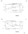
- FIG. 2( a ) is a graphical representation illustrating a TCM-ISDN downstream signal creating a NEXT on an upstream ADSL-DMT signal and a FEXT on a downstream ADSL-DMT signal
- FIG. 2( b ) is a graphical representation illustrating a TCM-ISDN upstream signal creating a NEXT on a downstream ADSL-DMT signal and a FEXT on an upstream ADSL-DMT signal.
- FIG. 3 is a simplified block diagram illustrating one embodiment of a cyclostationary equalizer structure and noise canceller for a Multicarrier system such as DMT.
- FIG. 4 is a simplified block diagram illustrating an alternative embodiment of a cyclostationary equalizer structure and noise canceller optimized to avoid aliasing.
- FIG. 5 is a simplified block diagram illustrating an alternative cyclostationary equalizer structure and noise canceller having fixed filters placed upstream from adaptive filters in accordance with an embodiment of the present invention.
- FIG. 6 is a simplified block diagram illustrating an alternative cyclostationary equalizer structure and noise canceller having fixed filters placed downstream from adaptive filters in accordance with an embodiment of the present invention.
- FIG. 7 is a simplified block diagram illustrating an alternative cyclostationary equalizer structure and noise canceller having one fixed filter placed upstream from demodulators in accordance with an embodiment of the present invention.
- FIG. 8 is a simplified block diagram illustrating an alternative cyclostationary equalizer structure and noise canceller having multiple fixed filters placed upstream from demodulators in accordance with an embodiment of the present invention.
- FIG. 9 is a simplified block diagram illustrating an alternative cyclostationary equalizer structure and noise canceller having fixed filters placed upstream from adaptive filters including a main path in accordance with an embodiment of the present invention.
- FIG. 10 is a simplified block diagram illustrating a structure of a time domain training of a cyclostationary TEQ, further illustrating a physical equalizer W and a target impulse response B.
- FIG. 11 is a graphical representation showing a typical bandwidth utilization of an ADSL DMT modem operating according to Annex B, without any ISDN noise canceller according to an embodiment of the present invention.
- FIG. 12 is a graphical representation showing a potential bandwidth utilization of an ADSL-DMT modem operating according to Annex B, with any ISDN noise canceller.
- FIG. 13 is a graphical representation showing a received ADSL-DMT downstream spectrum at channel output, with ISDN noise signal.
- FIG. 14 is a graphical representation showing a frequency shift operation on the received DMT plus the ISDN signal.
- FIG. 15 is a graphical representation showing a filtering operation of one of the TEQ branches.
- FIG. 16 is a graphical representation showing a result of combining the individual TEQ branches before presenting the output to the detector.
- FIG. 17( a ) is a graphical representation showing the W o equalizer match filtering the ADSL-DMT signal and rejecting the ISDN signal.
- FIG. 17( b ) is a graphical representation showing a shifted spectrum of 80 KHz of the ADSL-DMT signal and the ISDN signal filtered by the W 1 equalizer.
- FIG. 17( c ) is a graphical representation showing a shifted spectrum of 160 KHz of the ADSL-DMT signal and the ISDN signal filtered by the W 2 equalizer.
- FIG. 17( d ) is a graphical representation showing a first two ISDN in-band lobes being suppressed to a level below other noise levels.
- FIG. 18 is a simplified block diagram illustrating one embodiment of an equalizer structure for equalizing the channel and a separate cyclostationary noise canceller for a Multicarrier system such as DMT.
- FIG. 19 is a simplified block diagram illustrating an equalizer structure and a separate cyclostationary noise canceller with a one-tap filter in the main path in accordance with an embodiment of the present invention.
- FIG. 20 is a simplified block diagram illustrating another embodiment of a cyclostationary noise canceller training structure.
- FIG. 21 is a simplified block diagram illustrating a cyclostationary stand-alone noise canceller structure for a Multicarrier system such as DMT in accordance with one embodiment of the present invention.
- FIG. 22 is a simplified block diagram illustrating another embodiment of a cyclostationary canceller and equalizer training structure of the present invention.
- FIG. 23 is a simplified block diagram illustrating another embodiment of a cyclostationary canceller and equalizer training structure of the present invention.
- FIG. 24 is a simplified block diagram illustrating a combined cyclostationary canceller and equalizer training structure adapted for the training of the whole structure in accordance with one embodiment of the present invention.
- FIG. 25 is a simplified block diagram illustrating another embodiment of a combined cyclostationary canceller and equalizer training structure optimized for the training of the whole structure.
- FIG. 26 is a simplified block diagram illustrating a mathematical representation of a frequency shifter structure showing a complex operation.
- FIG. 27 is a simplified block diagram illustrating a mathematical representation of a frequency shifter structure showing a complex operation where only the real part is utilized.
- FIG. 28 is a simplified block diagram illustrating a mathematical representation of a frequency shifter structure showing a complex operation where both the real and imaginary parts are utilized.
- FIG. 29 is a simplified block diagram illustrating a reduced mathematical representation of a frequency shifter structure operation where only a single multiplication with a sine wave is performed.
- FIG. 30 is a simplified block diagram illustrating a cyclostationary equalizer structure and noise canceller having simple demodulation using a cosine or a sine in accordance with one embodiment of the present invention.
- One embodiment of the present invention is directed to a method and apparatus that significantly reduces the NEXT and FEXT interferences due to the presence of ISDN signals in the same bundle of twisted pair wires as an ADSL-DMT signal as recommended ITU-T G.992.1 Annex B and Annex C.
- FIG. 3 there is shown a simplified block diagram 300 illustrating a method and apparatus comprising the steps of receiving a signal 304 , that consists of the desired ADSL-DMT signal as well as the interfering ISDN signal from a channel.
- the received signal is demodulated with demodulators 312 , 314 and frequency-shifted by the baud rate of the interfering ISDN signal by frequency shifters 316 and 318 .
- the original signal is passed onto a time domain equalizer 306 , and the replicas of the received signal are passed to parallel time-domain equalizers 308 and 310 to remove the interference and preserve the desired signal.
- the output of the parallel time-domain equalizers are individually downsampled at downsamplers 320 , 322 and 324 in order to reduce the sampling rate.
- the downsampled signals are then added together at combiner 326 , where the frequency shifted side lobes of the ISDN interferer signal cancels each other in the parts of the spectrum shared with the ADSL DMT signal.
- the desired signal 328 is then passed onto other parts of the receiver, such as FFT and slicer for further processing.
- FIG. 4 there is shown a second embodiment of the present invention.
- the illustrated first alternative structure 300 conserves the higher sampling rates up until the recombination. Keeping a high sampling rate may avoid aliasing effects, that may have occurred if downsampling were performed before the recombination of the signals.
- a block diagram 400 is shown with one downsampler 422 , used after the recombination at 420 , in order to reduce the sampling rate before the signal is passed onto the detector for further processing.
- FIG. 5 there is shown a third embodiment of the present invention 500 , wherein downsamplers are not incorporated in the receiver structure.
- a plurality of filters 514 , 516 are incorporated in the respective frequency shifted paths.
- Such filters 514 , 516 may be fixed in that their implementation is to isolate the desired signal components off from the interferer.
- the filters 514 , 516 are selected from a group of filters consisting of low-pass, high-pass or band pass, and a fixed filter in the event that the interferer is known.
- the alternative embodiment disclosed teaches a method and apparatus of having the fixed filters 514 , 516 placed upstream from the adaptive filters 520 , 522 , in order to isolate the desired signal components 526 from the interferer.
- FIG. 6 there is shown a fourth embodiment 600 of the present invention.
- the embodiment of FIG. 6 is similar to that shown in FIG. 5 in that downsamplers are not provided, but which incorporate filters 620 , 622 in some of the respective frequency shifted paths.
- the fixed filters 620 , 622 are placed downstream from the adaptive filters 616 , 618 as shown in FIG. 6 .
- Another embodiment of the invention is a method and apparatus 700 , operating without downsamplers, but which incorporate the use of filters in the respective frequency shifted paths, such filters may be fixed in that their implementation is to isolate the desired signal components of the interferer only, such filters are selected from a group of filters consisting of low-pass, high-pass or band pass, and fixed one (given that the interferer is known).
- the alternative embodiment disclosed teaches a method and apparatus of having one fixed filter 706 , operating in one of the frequency-shifted paths and placed upstream from the demodulator 708 , in order to isolate the desired signal components from the overall signal and reject the interferer and by using only one filter and not utilizing any downsamplers, the receiver components are minimized, thereby reducing the size of the receiver as shown in FIG. 7 .
- FIG. 8 Another embodiment of the invention and in reference to FIG. 8 , there is shown a method and apparatus 800 , operating without downsamplers, but which incorporate filters in some of the respective frequency shifted paths, such filters may be fixed in that their implementation is to isolate the desired signal components of the interferer only, such filters are selected from a group of filters consisting of low-pass, high-pass or band pass, and fixed one (given that the interferer is known).
- the alternative embodiment is similar to the embodiment of FIG.
- filters 917 , 916 , and 918 are placed in the path of the main received signal as well as the respective frequency shifted paths, such filters may be fixed in that their implementation is to isolate the desired signal components of the interferer only, such filters are selected from a group of filters consisting of low-pass, high-pass or band pass, and fixed one when the interfering signal is known.
- filters 917 , 916 , and 918 are placed in the path of the main received signal as well as the respective frequency shifted paths, such filters may be fixed in that their implementation is to isolate the desired signal components of the interferer only, such filters are selected from a group of filters consisting of low-pass, high-pass or band pass, and fixed one when the interfering signal is known.
- FIG. 10 a method and apparatus of training the crosstalk canceller and equalizer of the present invention is disclosed herein.
- the desired signal and denoted by 1002 is transmitted through an unknown channel 1004 , that distorts the desired signal, the distorted signal is combined with background noise 1006 , by combiner 1008 , producing a received signal 1010 , and filtered by adaptive filters 1020 , 1022 and 1024 . Then the output of the filters is transmitted to respective downsamplers 1026 , 1028 and 1030 to produce filtered outputs.
- an adaptive algorithm is employed.
- a replica of the desired signal 1032 is locally generated at the receiver, and transmitted to a number of target filters 1044 , 1046 and 1048 .
- Error FIGS. 1056 , 1058 and 1060 are computed from the difference of the outputs of equalizers 1020 , 1022 , 1024 and impulse response target filters 1044 , 1046 and 1048 .
- the computed errors are then used to derive and compute both sets of equalizer coefficients (W 0 , W 1 , . . . W M ⁇ 1 ) and target impulse response coefficients (B 0 , B 1 , . . . . B M ⁇ 1 ); these error figures bare then used jointly or separately to derive the adaptive coefficients close to their optimum values with conventional adaptive algorithms such LMS, RLS, or constant modulus algorithm (CMA).
- LMS equalizer coefficients
- RLS constant modulus algorithm
- a method and apparatus 1800 of a crosstalk canceller in which an independent structure is located at the front of the receive section of a transceiver, where the equalization of the channel is not ensured by the crosstalk canceller 1814 , 1816 and 1818 , but rather by a subsequent Time Domain Equalizer (TEQ) structure 1824 . It is a separated channel, one for equalization and another for interference rejection apparatus and method.
- the equalizer's operation shown FIG. 18 is independent of the crosstalk remover.
- the role of the crosstalk canceller is to “clean up” the useful signal from in-band crosstalk before further processing.
- the training and optimization of the crosstalk canceller part can be done with or without the presence of the useful signal (in this case the DMT signal).
- the output signal 1822 in FIG. 18 is minimized, and as expected the crosstalk canceller operates in such a manner that it will cancel the interference by itself, across the whole spectrum represented in FIG. 1 , as desired.
- the spectral components present in each of the side-lobes of the interference signal may be used to completely cancel the other spectral components of the other side-lobes of the interferer.
- the filters 1814 , 1816 and 1818 constituting the crosstalk canceller may yield an undesirable effect on the useful signal, which will also propagate through the crosstalk canceller structure.
- Such undesirable effects may be (a) distortion in the direct path through filter 1814 , in FIG. 18 , and (b) folding the useful signal upon itself, creating a self-interference through the secondary frequency shifted paths and recombination at the canceller output.
- a simple delay 1914 is implemented in place of the filter 1814 in FIG. 18 in the direct path during training.
- Such an embodiment of the current invention prevents the primary path of the useful signal from being distorted. It can easily be obtained by constraining the filter 1814 in FIG. 18 to a single tap filter during training and steady-state operation.
- one exemplary embodiment of the present invention is to incorporate a training sequence that operates in the presence of both the useful signal and the interferer, such a method is illustrated in FIG. 20 , where the useful signal 2002 is transmitted through the channel, the channel represented by a simple delay 2004 for ease of understanding, at the same time, a replica of the useful signal 2002 , represented by 2028 in FIG. 20 which is noiseless is applied with a delay 2030 . At the output of the channel, a cyclostationary interference is added.
- the replica of the known training sequence 2028 is locally generated at the receiver (knowing the same sequence 2002 is being transmitted during a given moment of the start-up sequence), and then is used to perform the training of the crosstalk canceller.
- the optimization may not take place by minimizing the output of the crosstalk canceller itself, rather the optimization is achieved by minimizing the difference between the output of the canceller 2026 and a replica of the input noiseless sequence 2028 applied with a delay 2030 .
- the object of the embodiment is to have at the output of the crosstalk canceller a signal, which is close to or identical to the noiseless form 2002 .
- the crosstalk canceller removes the cyclostationary interference without affecting the useful signal.
- the error denoted by e 0 may be used to adapt the crosstalk canceller during the training sequence.
- the presence of the TEQ is not necessary, the channel being a pure delay does not introduce distortion to the useful signal. Hence, the TEQ need not undo any distortion.
- a TEQ 2230 will be necessary, and can possibly be placed downstream from the crosstalk cancellers 2220 , 2222 , and 2224 .
- an embodiment of the current invention is to place an additional filter 2236 for the training phase. Its presence is necessary since the useful signal 2202 to which it is desired to have the crosstalk's output resemble as closely as possible, suffers attenuation and distortion through the unknown channel 2204 . After proper convergence, it is expected that the filter 2236 would become a replica of the unknown channel 2204 .
- the filter 2236 could also be devised independently through proper channel estimation, before the training of the crosstalk cancellers 2220 , 2222 , and 2224 .
- both convergence of the filter 2236 and the crosstalk cancellers 2220 , 2222 , and 2224 can be achieved jointly in an adaptive manner.
- the objective of the training of the crosstalk cancellers 2220 , 2222 , and 2224 remains identical as in the manner outlined earlier, to ensure that its output resembles as closely as possible the known noiseless sequence 2232 applied to filter 2236 , which is expected to approach a replica of 2204 .
- the cancellers 2220 , 2222 , and 2224 In order for the crosstalk canceller's 2220 , 2222 , and 2224 output to be similar to a noiseless output of the channel 2204 , the cancellers 2220 , 2222 , and 2224 has to remove most of the interferer disturbance. Once that is achieved, the output of the crosstalk canceller 2228 can then be fed to the TEQ 2230 for channel equalization.
- the time domain equalizer, TEQ 2330 is trained after a successful training of the crosstalk cancellers 2320 , 2322 , and 2324 in the same manner depicted in FIG. 22 with which a classical TEQ would be trained in DMT.
- the TEQ is trained, such that its output matches as closely as possible the output of a so-called target filter 2336 of a specified length (Cyclic prefix length) fed with a replica of the noiseless known training sequence 2332 .
- the crosstalk cancellers 2320 , 2322 , and 2324 frozen with their optimum coefficients during the TEQ training, removing all cyclostationary disturber, without affecting the useful signal.
- the TEQ training therefore takes place as if there were no disturber.
- the optimization of the TEQ is done such that the combined channel C(n)/TEQ impulse response does not exceed the target impulse response of target filter 2336 , corresponding to the cyclic prefix length of a DMT system.
- ISI inter-symbol interference
- ICI Inter-Channel Interference
- the crosstalk canceller propagates the receive signal (useful and interference) in it's direct path.
- the TEQ 2330 then equalizes the noiseless, useful signal to the cyclic prefix length. It is an independent equalizer and crosstalk canceller structure. However, the crosstalk canceller has been trained in the presence of the useful signal, in order not to degrade it.
- a target filter 2434 is introduced into the structure and the TEQ filter is incorporated in the direct path of the crosstalk canceller as filter 2420 , so that the training of the crosstalk canceller is done jointly with the one of the TEQ.
- the filter coefficients are derived such that the combination of the output of the TEQ filter with the output of the crosstalk canceller matches as close as possible in a minimum mean square error sense, the output of the target filter 2434 of a cyclic prefix length fed by a replica of the noiseless transmitted sequence 2430 .
- two objectives of the filter structure maybe achieved, equalizing the useful signal to the cyclic prefix length and rejecting the cyclostationary interference.
- the filters tend to filter not only the side-lobes of the interference signal in order to cancel it in the main branch, as they would have in a separate crosstalk TEQ structure, but to some extent, some energy of the useful signal is let through in the same manner.
- some energy of the useful signal is let through the secondary paths, it is needed to ensure that the corresponding target impulse response of the combined channel and secondary paths be shorter than the cyclic prefix length, otherwise, the undesirable effect will be to create ISI and ICI through the secondary frequency shifted branches, similar to the one that would be created if the B 0 target impulse response length were exceeded in the main path.
- a series of target impulse responses filters 2542 , 2544 , and 2546 with frequency shifts, which will be used to constrain the respective combined channel 2504 and the filters 2520 , 2522 and 2524 below the cyclic prefix length is included in the structure.
- undesirable ISI and ICI effects are limited, when the useful signal energy propagates through the secondary paths.
- the error signals e 0 , e 1 , . . . e M ⁇ 1 can be used individually or in any combination to adapt the various filters 2520 , 2522 and 2524 and target filters 2542 , 2544 , and 2546 .
Abstract
Description
Claims (28)
Priority Applications (1)
| Application Number | Priority Date | Filing Date | Title |
|---|---|---|---|
| US10/618,678 US7289554B2 (en) | 2003-07-15 | 2003-07-15 | Method and apparatus for channel equalization and cyclostationary interference rejection for ADSL-DMT modems |
Applications Claiming Priority (1)
| Application Number | Priority Date | Filing Date | Title |
|---|---|---|---|
| US10/618,678 US7289554B2 (en) | 2003-07-15 | 2003-07-15 | Method and apparatus for channel equalization and cyclostationary interference rejection for ADSL-DMT modems |
Publications (2)
| Publication Number | Publication Date |
|---|---|
| US20050013353A1 US20050013353A1 (en) | 2005-01-20 |
| US7289554B2 true US7289554B2 (en) | 2007-10-30 |
Family
ID=34062446
Family Applications (1)
| Application Number | Title | Priority Date | Filing Date |
|---|---|---|---|
| US10/618,678 Expired - Fee Related US7289554B2 (en) | 2003-07-15 | 2003-07-15 | Method and apparatus for channel equalization and cyclostationary interference rejection for ADSL-DMT modems |
Country Status (1)
| Country | Link |
|---|---|
| US (1) | US7289554B2 (en) |
Cited By (8)
| Publication number | Priority date | Publication date | Assignee | Title |
|---|---|---|---|---|
| US20110058468A1 (en) * | 2009-09-08 | 2011-03-10 | Singh Shailendra K | Method and apparatus for crosstalk cancellation during SELT testing |
| US8737188B1 (en) | 2012-01-11 | 2014-05-27 | Audience, Inc. | Crosstalk cancellation systems and methods |
| US9437180B2 (en) | 2010-01-26 | 2016-09-06 | Knowles Electronics, Llc | Adaptive noise reduction using level cues |
| US9502048B2 (en) | 2010-04-19 | 2016-11-22 | Knowles Electronics, Llc | Adaptively reducing noise to limit speech distortion |
| US9536540B2 (en) | 2013-07-19 | 2017-01-03 | Knowles Electronics, Llc | Speech signal separation and synthesis based on auditory scene analysis and speech modeling |
| US9640194B1 (en) | 2012-10-04 | 2017-05-02 | Knowles Electronics, Llc | Noise suppression for speech processing based on machine-learning mask estimation |
| US9799330B2 (en) | 2014-08-28 | 2017-10-24 | Knowles Electronics, Llc | Multi-sourced noise suppression |
| US9830899B1 (en) | 2006-05-25 | 2017-11-28 | Knowles Electronics, Llc | Adaptive noise cancellation |
Families Citing this family (10)
| Publication number | Priority date | Publication date | Assignee | Title |
|---|---|---|---|---|
| CN100414886C (en) * | 2005-09-30 | 2008-08-27 | 华为技术有限公司 | Method and apparatus of determining working scene of DSL transceiver |
| CN101197592B (en) | 2006-12-07 | 2011-09-14 | 华为技术有限公司 | Far-end cross talk counteracting method and device, signal transmission device and signal processing system |
| CN101197798B (en) * | 2006-12-07 | 2011-11-02 | 华为技术有限公司 | Signal processing system, chip, circumscribed card, filtering and transmitting/receiving device and method |
| CN101202552B (en) * | 2006-12-15 | 2012-01-25 | 华为技术有限公司 | Crossfire counteract apparatus, signal processing system and crossfire counteract method |
| TWI331861B (en) * | 2007-01-24 | 2010-10-11 | Realtek Semiconductor Corp | Null symbol detecting device and method |
| EP1976121A1 (en) * | 2007-03-31 | 2008-10-01 | Sony Deutschland Gmbh | Digital filter |
| US9154186B2 (en) * | 2012-12-04 | 2015-10-06 | Schlumberger Technology Corporation | Toolstring communication in cable telemetry |
| CN105099970B (en) | 2014-04-24 | 2018-08-14 | 富士通株式会社 | Adaptive equalizer, adaptive equilibrium method and receiver |
| JP2018129618A (en) * | 2017-02-07 | 2018-08-16 | 富士通株式会社 | Receiving device and receiving method |
| US11695445B2 (en) | 2020-08-06 | 2023-07-04 | Samsung Electronics Co., Ltd. | Equalizer assisted polynomial based linearity enhancement and self-interference canceler |
Citations (8)
| Publication number | Priority date | Publication date | Assignee | Title |
|---|---|---|---|---|
| US5566167A (en) * | 1995-01-04 | 1996-10-15 | Lucent Technologies Inc. | Subband echo canceler |
| US5859914A (en) * | 1996-07-23 | 1999-01-12 | Nec Corporation | Acoustic echo canceler |
| US5991311A (en) | 1997-10-25 | 1999-11-23 | Centillium Technology | Time-multiplexed transmission on digital-subscriber lines synchronized to existing TCM-ISDN for reduced cross-talk |
| US6266347B1 (en) | 1998-12-08 | 2001-07-24 | Globespan, Inc. | System and method for modifying symbol duration for the efficient transmission of information in a time duplex noise environment |
| US6393051B1 (en) | 1998-06-30 | 2002-05-21 | Fujitsu Limited | Digital subscriber line communicating system and a transceiver in the system |
| US6944289B2 (en) * | 2002-10-01 | 2005-09-13 | Motorola, Inc. | Delay insertion for echo cancellation, with echo supression, in a communication network |
| US6999504B1 (en) * | 2000-11-21 | 2006-02-14 | Globespanvirata, Inc. | System and method for canceling crosstalk |
| US6999517B1 (en) * | 2000-06-07 | 2006-02-14 | Sehlumberger Technology Corporation | Method and apparatus for transmission of data on multiple propagation modes with far-end cross-talk cancellation |
-
2003
- 2003-07-15 US US10/618,678 patent/US7289554B2/en not_active Expired - Fee Related
Patent Citations (8)
| Publication number | Priority date | Publication date | Assignee | Title |
|---|---|---|---|---|
| US5566167A (en) * | 1995-01-04 | 1996-10-15 | Lucent Technologies Inc. | Subband echo canceler |
| US5859914A (en) * | 1996-07-23 | 1999-01-12 | Nec Corporation | Acoustic echo canceler |
| US5991311A (en) | 1997-10-25 | 1999-11-23 | Centillium Technology | Time-multiplexed transmission on digital-subscriber lines synchronized to existing TCM-ISDN for reduced cross-talk |
| US6393051B1 (en) | 1998-06-30 | 2002-05-21 | Fujitsu Limited | Digital subscriber line communicating system and a transceiver in the system |
| US6266347B1 (en) | 1998-12-08 | 2001-07-24 | Globespan, Inc. | System and method for modifying symbol duration for the efficient transmission of information in a time duplex noise environment |
| US6999517B1 (en) * | 2000-06-07 | 2006-02-14 | Sehlumberger Technology Corporation | Method and apparatus for transmission of data on multiple propagation modes with far-end cross-talk cancellation |
| US6999504B1 (en) * | 2000-11-21 | 2006-02-14 | Globespanvirata, Inc. | System and method for canceling crosstalk |
| US6944289B2 (en) * | 2002-10-01 | 2005-09-13 | Motorola, Inc. | Delay insertion for echo cancellation, with echo supression, in a communication network |
Non-Patent Citations (1)
| Title |
|---|
| Koen Vanbleu, Geert Ysebaert, Marc Moonen, Piet Vandaele; "Combined Equalization and Alien Crosstalk Cancellation in ADSL Receivers"; Proc. 3<SUP>rd </SUP>IEEE Benelux Signal Processing Symposium (SPS-2002), Belgium, Mar. 21-22, 2002; vanbleu,ysebaert,moonen@esat.kuleuven.ac.be; piet.vandaele@alcatel.be. |
Cited By (9)
| Publication number | Priority date | Publication date | Assignee | Title |
|---|---|---|---|---|
| US9830899B1 (en) | 2006-05-25 | 2017-11-28 | Knowles Electronics, Llc | Adaptive noise cancellation |
| US20110058468A1 (en) * | 2009-09-08 | 2011-03-10 | Singh Shailendra K | Method and apparatus for crosstalk cancellation during SELT testing |
| US8767521B2 (en) | 2009-09-08 | 2014-07-01 | Ikanos Communications Inc. | Method and apparatus for crosstalk cancellation during SELT testing |
| US9437180B2 (en) | 2010-01-26 | 2016-09-06 | Knowles Electronics, Llc | Adaptive noise reduction using level cues |
| US9502048B2 (en) | 2010-04-19 | 2016-11-22 | Knowles Electronics, Llc | Adaptively reducing noise to limit speech distortion |
| US8737188B1 (en) | 2012-01-11 | 2014-05-27 | Audience, Inc. | Crosstalk cancellation systems and methods |
| US9640194B1 (en) | 2012-10-04 | 2017-05-02 | Knowles Electronics, Llc | Noise suppression for speech processing based on machine-learning mask estimation |
| US9536540B2 (en) | 2013-07-19 | 2017-01-03 | Knowles Electronics, Llc | Speech signal separation and synthesis based on auditory scene analysis and speech modeling |
| US9799330B2 (en) | 2014-08-28 | 2017-10-24 | Knowles Electronics, Llc | Multi-sourced noise suppression |
Also Published As
| Publication number | Publication date |
|---|---|
| US20050013353A1 (en) | 2005-01-20 |
Similar Documents
| Publication | Publication Date | Title |
|---|---|---|
| US7289554B2 (en) | Method and apparatus for channel equalization and cyclostationary interference rejection for ADSL-DMT modems | |
| US6266367B1 (en) | Combined echo canceller and time domain equalizer | |
| US7020212B1 (en) | Method and system for a multiple dimensional adaptive frequency domain noise canceler for DMT transceivers | |
| EP0933897B1 (en) | Reduction of interference in duplex discrete multitone communications systems | |
| US7577084B2 (en) | ISDN crosstalk cancellation in a DSL system | |
| EP1043875B1 (en) | Receiver for discrete multitone modulated signals having window function | |
| US8265215B1 (en) | Method and system for determining symbol boundary timing in a multicarrier data transmission system | |
| US6628704B1 (en) | Equalizer training for ADSL transceivers under TCM-ISDN crosstalk environment | |
| US6377683B1 (en) | Low complexity frequency domain echo canceller for DMT transceivers | |
| US8144807B2 (en) | Crosstalk cancellation in digital subscriber line communications | |
| Cioffi et al. | Very-high-speed digital subscriber lines | |
| US6404806B1 (en) | Method and apparatus for time-domain equalization in FDM-based discrete multi-tone modems | |
| JP2007195218A (en) | Digital radio frequency interference canceller | |
| US7978591B2 (en) | Mitigation of interference and crosstalk in communications systems | |
| Vandendorpe et al. | Fractionally spaced linear and decision-feedback detectors for transmultiplexers | |
| US7817730B2 (en) | Training sequence for symbol boundary detection in a multicarrier data transmission system | |
| US6658049B1 (en) | xDSL repeater system and method | |
| US7035326B1 (en) | Method and apparatus for initializing modem communications | |
| US20060203896A1 (en) | Semi-digital duplexing | |
| US8908489B2 (en) | Method and device for data processing and communication system comprising such device | |
| WO2006121073A1 (en) | Multiplex transmission device, and multiplex transmission method | |
| US6781965B1 (en) | Method and apparatus for echo cancellation updates in a multicarrier transceiver system | |
| US7274736B2 (en) | Multiple path equalization for multicarrier systems | |
| KR100512172B1 (en) | Asymmetric digital subscriber line system | |
| Khan et al. | Channel equalization for Discrete Wavelet Multitone transceiver in wireline channels |
Legal Events
| Date | Code | Title | Description |
|---|---|---|---|
| AS | Assignment |
Owner name: GLOBESPAN VIRATA INC, NEW JERSEY Free format text: ASSIGNMENT OF ASSIGNORS INTEREST;ASSIGNOR:ALLOIN, LAURENT FRANCIS;REEL/FRAME:014284/0549 Effective date: 20030707 |
|
| AS | Assignment |
Owner name: CONEXANT, INC.,NEW JERSEY Free format text: CHANGE OF NAME;ASSIGNOR:GLOBESPANVIRATA, INC.;REEL/FRAME:018471/0286 Effective date: 20040528 Owner name: CONEXANT, INC., NEW JERSEY Free format text: CHANGE OF NAME;ASSIGNOR:GLOBESPANVIRATA, INC.;REEL/FRAME:018471/0286 Effective date: 20040528 |
|
| AS | Assignment |
Owner name: BANK OF NEW YORK TRUST COMPANY, N.A., THE,ILLINOIS Free format text: SECURITY AGREEMENT;ASSIGNOR:BROOKTREE BROADBAND HOLDING, INC.;REEL/FRAME:018573/0337 Effective date: 20061113 Owner name: BANK OF NEW YORK TRUST COMPANY, N.A., THE, ILLINOI Free format text: SECURITY AGREEMENT;ASSIGNOR:BROOKTREE BROADBAND HOLDING, INC.;REEL/FRAME:018573/0337 Effective date: 20061113 |
|
| AS | Assignment |
Owner name: BROOKTREE BROADBAND HOLDING, INC.,CALIFORNIA Free format text: ASSIGNMENT OF ASSIGNORS INTEREST;ASSIGNOR:GLOBESPANVIRATA, INC.;REEL/FRAME:018826/0939 Effective date: 20040228 Owner name: BROOKTREE BROADBAND HOLDING, INC., CALIFORNIA Free format text: ASSIGNMENT OF ASSIGNORS INTEREST;ASSIGNOR:GLOBESPANVIRATA, INC.;REEL/FRAME:018826/0939 Effective date: 20040228 |
|
| STCF | Information on status: patent grant |
Free format text: PATENTED CASE |
|
| AS | Assignment |
Owner name: BROOKTREE BROADBAND HOLDING, INC, CALIFORNIA Free format text: RELEASE BY SECURED PARTY;ASSIGNOR:THE BANK OF NEW YORK MELLON TRUST COMPANY, N.A.;REEL/FRAME:023148/0566 Effective date: 20090821 Owner name: BROOKTREE BROADBAND HOLDING, INC,CALIFORNIA Free format text: RELEASE BY SECURED PARTY;ASSIGNOR:THE BANK OF NEW YORK MELLON TRUST COMPANY, N.A.;REEL/FRAME:023148/0566 Effective date: 20090821 |
|
| AS | Assignment |
Owner name: IKANOS COMMUNICATIONS, INC., CALIFORNIA Free format text: ASSIGNMENT OF ASSIGNORS INTEREST;ASSIGNORS:CONEXANT SYSTEMS, INC.;CONEXANT, INC.;BROOKTREE BROADBAND HOLDING INC.;REEL/FRAME:023163/0723 Effective date: 20090824 Owner name: IKANOS COMMUNICATIONS, INC.,CALIFORNIA Free format text: ASSIGNMENT OF ASSIGNORS INTEREST;ASSIGNORS:CONEXANT SYSTEMS, INC.;CONEXANT, INC.;BROOKTREE BROADBAND HOLDING INC.;REEL/FRAME:023163/0723 Effective date: 20090824 |
|
| FPAY | Fee payment |
Year of fee payment: 4 |
|
| FPAY | Fee payment |
Year of fee payment: 8 |
|
| AS | Assignment |
Owner name: ALCATEL-LUCENT USA, INC., NEW JERSEY Free format text: NOTICE OF GRANT OF SECURITY INTEREST IN PATENTS;ASSIGNOR:IKANOS COMMUNICATIONS, INC.;REEL/FRAME:035581/0710 Effective date: 20150430 |
|
| AS | Assignment |
Owner name: SILICON VALLEY BANK, CALIFORNIA Free format text: SECURITY INTEREST;ASSIGNOR:IKANOS COMMUNICATIONS, INC.;REEL/FRAME:035874/0351 Effective date: 20150602 |
|
| AS | Assignment |
Owner name: IKANOS COMMUNICATIONS, INC., CALIFORNIA Free format text: RELEASE BY SECURED PARTY;ASSIGNOR:ALCATEL-LUCENT USA, INC.;REEL/FRAME:036732/0876 Effective date: 20150929 Owner name: IKANOS COMMUNICATIONS, INC., CALIFORNIA Free format text: RELEASE BY SECURED PARTY;ASSIGNOR:SILICON VALLEY BANK;REEL/FRAME:036733/0031 Effective date: 20150930 |
|
| FEPP | Fee payment procedure |
Free format text: MAINTENANCE FEE REMINDER MAILED (ORIGINAL EVENT CODE: REM.); ENTITY STATUS OF PATENT OWNER: LARGE ENTITY |
|
| LAPS | Lapse for failure to pay maintenance fees |
Free format text: PATENT EXPIRED FOR FAILURE TO PAY MAINTENANCE FEES (ORIGINAL EVENT CODE: EXP.); ENTITY STATUS OF PATENT OWNER: LARGE ENTITY |
|
| STCH | Information on status: patent discontinuation |
Free format text: PATENT EXPIRED DUE TO NONPAYMENT OF MAINTENANCE FEES UNDER 37 CFR 1.362 |
|
| FP | Lapsed due to failure to pay maintenance fee |
Effective date: 20191030 |