US7307655B1 - Method and apparatus for displaying a synthesized image viewed from a virtual point of view - Google Patents
Method and apparatus for displaying a synthesized image viewed from a virtual point of view Download PDFInfo
- Publication number
- US7307655B1 US7307655B1 US09/744,787 US74478799A US7307655B1 US 7307655 B1 US7307655 B1 US 7307655B1 US 74478799 A US74478799 A US 74478799A US 7307655 B1 US7307655 B1 US 7307655B1
- Authority
- US
- United States
- Prior art keywords
- camera
- image
- vehicle
- point
- space
- Prior art date
- Legal status (The legal status is an assumption and is not a legal conclusion. Google has not performed a legal analysis and makes no representation as to the accuracy of the status listed.)
- Expired - Lifetime
Links
Images


Classifications
-
- G—PHYSICS
- G06—COMPUTING; CALCULATING OR COUNTING
- G06T—IMAGE DATA PROCESSING OR GENERATION, IN GENERAL
- G06T15/00—3D [Three Dimensional] image rendering
- G06T15/10—Geometric effects
- G06T15/20—Perspective computation
-
- G—PHYSICS
- G06—COMPUTING; CALCULATING OR COUNTING
- G06T—IMAGE DATA PROCESSING OR GENERATION, IN GENERAL
- G06T15/00—3D [Three Dimensional] image rendering
- G06T15/10—Geometric effects
-
- G—PHYSICS
- G06—COMPUTING; CALCULATING OR COUNTING
- G06V—IMAGE OR VIDEO RECOGNITION OR UNDERSTANDING
- G06V20/00—Scenes; Scene-specific elements
- G06V20/50—Context or environment of the image
- G06V20/56—Context or environment of the image exterior to a vehicle by using sensors mounted on the vehicle
Definitions
- the present invention relates to an apparatus and a method for displaying a synthesized single image composed of a plurality of images shot by plural cameras, instead of displaying the images independently, so that the overall situation of the area shot by said plural cameras can be intuitionally understood, and for example, to a monitoring apparatus in a shop or a vehicle's surroundings monitoring apparatus, etc. for the assistance of the safety confirmation during the driving of a vehicle.
- a prior art general monitoring apparatus is generally configured so that a monitoring objective part in a shop and the like is shot by a camera or plural cameras and that the image(s) is displayed on a monitor screen.
- the same number of monitor screens as the number of said cameras are generally prepared.
- the images of said plural cameras are integrated into a single image using a separator and the like, the camera images are sequentially switched, or another method is used.
- a manager needs to consider the continuity between the independently displayed images during the monitoring of the image of each camera in such a prior art apparatus.
- Japanese Laid-Open Patent Publication No. Hei 10-164566 discloses a monitoring apparatus in which a plurality of cameras are installed so that the images thereof overlap at the edge parts and in which the images of the plurality of cameras are integrated and displayed into a single image by superposing said overlapping parts, thereby resolving said problem of continuity.
- FIG. 1 Another example of the application of a monitoring apparatus is the case of the installation on a vehicle.
- a monitoring apparatus in which a camera is installed for monitoring the surroundings of a vehicle and the image acquired by said camera is displayed on a TV monitor installed near the driver's seat.
- An apparatus is known in which a place, such as the rear side of the vehicle, unseen to the driver with the own eyes or a mirror is shot by said camera and displayed on said monitor.
- many are used on a vehicle, such as a large truck and a van (one-box wagon), having a narrow field of view seen with the eyes and a mirror.
- FIG. 69 shows a prior art example in which monitoring cameras are installed on a vehicle.
- the example of FIG. 69 is a method in which the images of four monitoring cameras (C 1 -C 4 ) mounted on the body of the vehicle are synthesized into a single image through a separating adapter and the images are separately displayed on a TV monitor (D 1 -D 4 ).
- an invention is made so that the right and left of the image is reversed in order that the positional relation of the objects viewed in the image becomes the same as viewed in a mirror.
- an invention is made so that each camera is turned by manual operation by the driver thereby permitting to obtain the image of the desired place.
- a monitoring apparatus mentioned above is disclosed, for example, in Japanese Laid-Open Patent Publication No. Hei 5-310078, and so on.
- the apparatus cannot treat, for example, a request by the manager to watch an integrated image viewed from a desired point of view depending on the situation, because the apparatus does not calculate the spatial position of an object shot by the camera.
- the same problem occurs in a monitoring apparatus installed on a vehicle. That is, in a prior art monitoring apparatus such as the above-mentioned example, the images input from respective cameras are displayed independently of each other. Accordingly, for example, in case of using said displayed images as assistance during the parking of a vehicle in a parking space, said images merely serve to provide a view otherwise unseen. That is, the only effect is to reduce the area unseen to the driver in comparison with the conventional case by visual inspection and a mirror.
- a wide-angle lens is generally used in order to overcome the narrowness of the field.
- the image from the wide-angle lens does not provide the detail in a specific part.
- the overall situation of the surroundings of the vehicle is easily understood because of the wideness of the field of the wide-angle lens.
- the image of the camera still depends on the position on the body of a vehicle where the camera is installed, and accordingly, it is not possible to obtain a virtual image viewed from a position where the camera is not installed. That is, the only effect of using the camera equipped with the wide-angle lens is to reduce the number of the cameras.
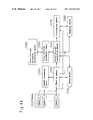
- FIG. 70 is a block diagram showing an embodiment of the prior art apparatus for monitoring the surroundings of a vehicle.
- the images input from cameras 1 -N 2201 into an image converting section 2202 are converted into another coordinates by a conversion, and synthesized into a single image by an image displaying section 2203 . It is then displayed on a TV monitor 2204 installed at the driver's seat.
- an invention is possible in which the displayed position of the vehicle in question is shifted from the center of the screen or the like, depending on gear position, vehicle speed, and winker operation in order to widen the area of interest of the surroundings of the vehicle, and the like.
- the viewed image of the objects outside of the road surface is cut out and pasted into a synthesized image.
- the cutting-out of the objects outside of the road surface is one of the difficult problems in the field of image recognition, and hence difficult to realize practically.
- an object of the present invention is to compose a single image showing what objects are present near the vehicle in the all surroundings of the vehicle, as realistically and understandably as possible, thereby displaying it to the driver.
- the present invention further provides a method for easily obtaining camera parameters, such as the attachment position and the attachment angle of the camera, and also an apparatus and a method for detecting and correcting the shift of said camera parameters due to vibration, temperature and the like, if it occurs during the running.
- the present invention is an image generating apparatus comprising: a camera or a plurality of cameras; space reconstructing means for mapping the input image from said camera, into a predetermined space model of a predetermined three-dimensional space; point-of-view converting means for synthesizing an image viewed from an arbitrary virtual point of view in said predetermined three-dimensional space by referencing to said space data mapped by said space reconstructing means; and displaying means for displaying the image converted by said point-of-view converting means.
- the basic configuration of the present invention is characterized by comprising: image inputting means of inputting an image or images from a camera or a plurality of cameras installed on a vehicle; a camera parameter table for storing the camera parameters indicating the characteristics of said camera or cameras; space model generating means of generating a space model in a coordinate system with the reference on the vehicle; mapping means of mapping the image input from said camera, into said space model; point-of-view converting means of setting a point of view and synthesizing a single image viewed from said point of view using the data converting means.
- the space model generating means generates a model previously set properly or a model set depending on the distance of an obstacle in the surroundings of the vehicle sensed by an obstacle sensing means.
- the mapping means maps, into said space model, the image of the surroundings of the vehicle input by the image inputting means from the camera installed on the vehicle.
- the point-of-view converting means composes a single image viewed from a predetermined point of view using the mapped image, and the displaying means displays it.
- the crew of the vehicle can cause displaying the image viewed from a desired point of view.
- the basic configuration of the present invention is characterized by comprising: image inputting means of inputting an image or images from a camera or a plurality of cameras installed on a vehicle; a camera parameter table for storing the camera parameters indicating the characteristics of said camera or cameras; road-surface characteristics detecting means of detecting the characteristics on the road surface as the situation of the surroundings of the vehicle; space model generating means of generating a space model corresponding to the process result of said road-surface characteristics detecting means in a coordinate system with the reference on the vehicle; mapping means of mapping the image input from said camera, into said space model; point-of-view converting means of setting a point of view and synthesizing a single image viewed from said point of view using the data generated by said mapping means; and displaying means of displaying the image converted by said point-of-view converting means.
- the first applied configuration of the present invention is characterized by further comprising: movement direction detecting means for detecting the movement direction of said vehicle; and movement distance detecting means for detecting the movement distance of the vehicle in a unit time; and wherein said apparatus successively corrects said space model depending on the present position of the characteristics on the road surface obtained from the process results of said movement direction detecting means and said movement distance detecting means.
- the second applied configuration of the present invention is characterized by comprising characteristics correcting means for correcting the process result while displaying the process result of said road-surface characteristics detecting means on said displaying means.
- the road-surface characteristics detecting means detects the characteristics, such as a white line, on the road surface, and the space model generating means generates a space model correspondingly to said detected characteristics.
- the mapping means maps, into said space model, the image of the surroundings of the vehicle input by the image inputting means from the camera installed on the vehicle. Then, the point-of-view converting means composes a single image viewed from a predetermined point of view using the mapped image, and the displaying means displays it. Since the positional relation between the vehicle and the road surface characteristics changes as the vehicle moves, the space model is corrected in response to the change, and an image is synthesized using the corrected space model and then displayed.
- the present invention is characterized by comprising: image inputting means of inputting an image or images from a camera or a plurality of cameras installed on a vehicle; a camera parameter table for storing the camera parameters indicating the characteristics of said camera or cameras; mapping means of mapping the image input from said camera, into a space model generated by modeling the surroundings of said vehicle; point-of-view converting means of synthesizing a single image viewed from a desired virtual point of view using the data generated by said mapping means; camera parameter correcting means of correcting the parameters of said camera or cameras for each camera independently; and displaying means of displaying the image converted by said point-of-view converting means.
- Said point-of-view converting means is characterized by switching said virtual point of view according to the time of process or the time of normal operation of said camera parameter correcting means.
- Said point-of-view converting means makes said virtual point of view consistent with the camera parameter of any of said cameras on a vehicle in the time of process of said camera parameter correcting means.
- Said point-of-view converting means makes said virtual point of view consistent with the yet-corrected camera parameter of the camera being under the correction, in the time of process of said camera parameter correcting means.
- the direction of the operation of changing the direction of the point of view is set to be reverse to the direction of said point of view, in said point-of-view converting means.
- Said displaying means displays a mark indicating a boundary, in superposition on the synthesized image in the boundary part where respective images contact when displaying the image from each camera.
- the present invention is characterized by comprising: image inputting means of inputting an image or images from a camera or a plurality of cameras installed on a vehicle; a camera parameter table for storing the camera parameters indicating the characteristics of said camera or cameras; mapping means of mapping the image input from said camera, into a space model generated by modeling the surroundings of the vehicle; a point-of-view parameter table for storing the point-of-view parameters including at least the position and the orientation; point-of-view converting means of synthesizing an image viewed from a desired virtual point of view using the result of the mapping process by said mapping means; point-of-view parameter correcting means of correcting the parameters of said virtual point of view; and displaying means of displaying the image converted by said point-of-view converting means.
- the present invention is characterized by said set of the point-of-view parameters being distinguished so as to correspond to any one of the cameras installed on the vehicle and stored in said point-of-view parameter table.
- the direction of operation is set to be reverse to the actual alteration of point-of-view parameter at least for the operations in orientation, position, and rotation among the operations of changing said virtual-point-of-view parameter in said point-of-view parameter correcting means.
- Said point-of-view parameter correcting means corrects said virtual-point-of-view parameter, a fixed tentative virtual point of view is provided, and the progress of the correction of the virtual point of view being under the correction is successively displayed as a synthesized image viewed from said tentative virtual point of view.
- Said displaying means displays a mark indicating a boundary, in superposition on the synthesized image in the boundary part where respective images contact when displaying the image from each camera.
- the present invention is characterized by comprising a mapping table for retaining the pixel correspondence relation between the camera input image and the synthesized image, whereby said correspondence relation obtained in the processes by said mapping means and said point-of-view converting means is stored in said mapping table.
- mapping table correcting means of re-calculating said mapping table using the point-of-view parameters altered in the process by the point-of-view parameter correcting means.
- FIG. 1 is a block diagram showing an example of the basic configuration of an image generating apparatus in accordance with the present invention (Claim 1 ).
- FIG. 2 is a block diagram showing an example of the configuration of an image generating apparatus in accordance with the combination of the present inventions of Claims 8 , 9 and 12 [sic; 8 , 9 and 12 ].
- FIG. 3 is a block diagram showing an example of the configuration of an image generating apparatus in accordance with the present invention (Claim 14 ).
- FIG. 4 is a block diagram showing an example of the configuration of an image generating apparatus in accordance with the present invention (Claim 17 ).
- FIG. 5 is a block diagram showing an example of the configuration of an image generating apparatus in accordance with the present invention (Claim 18 ).
- FIG. 6 is a block diagram showing an image generating apparatus as the integration of FIGS. 1 to 5 .
- FIG. 7 is a conceptual diagram showing an example of the mounting of a camera onto a vehicle.
- FIG. 8 is a conceptual diagram representing the correspondence relation between a point of the U-V coordinate system being set on the plane including an image shot by a camera and a point of the three-dimensional space coordinate system.
- FIG. 9 is a diagram showing the data stored in a camera parameter table 103 , in the form of a table.
- FIG. 10 is a diagram showing an example of a temperature correction table 111 , in the form of a table.
- FIG. 11 is a diagram showing an example of a camera parameter table 103 renewed using a temperature degree [sic; temperature] correction table, in the form of a table.
- FIG. 12 is a diagram showing an example of the description of a space data buffer 105 for storing space data, in the form of a table.
- FIG. 13 is a conceptual diagram of the positional relation between the characteristic points on the road surface and the vehicle, viewed from above.
- FIG. 15 is a conceptual diagram showing an image of the road surface including said characteristic points, shot by the car-carried camera 2 of FIG. 13 .
- FIG. 16 is a conceptual diagram of the positional relation between characteristic points A, B, C on the road surface and the vehicle, viewed from above.
- FIG. 17 is a conceptual diagram showing an image of the road surface including said characteristic points A, B, shot by the car-carried camera 1 of FIG. 16 .
- FIG. 18 is a conceptual diagram showing an image of the road surface including said characteristic points B, C, shot by the car-carried camera 2 of FIG. 16 .
- FIG. 19 is a conceptual diagram showing the situation of the synthesizing of an image viewed from a virtual camera, by point-of-view converting means 106 in accordance with the present invention using the images shot by the car-carried cameras 1 and 2 of FIG. 16 .
- FIG. 20 shows:
- FIG. 21 shows:
- (c) a conceptual diagram showing the situation that the rectangle patterns irradiated onto the road surface are shot by a camera.
- FIG. 23 is a flow chart showing the procedure of the process in space data converting means 114 .
- FIG. 24 is a conceptual diagram used for the assistance of the description of space data converting means 114 .
- FIG. 26 is a flow chart showing the flow of the overall process of an image generating apparatus in accordance with the present invention.
- FIG. 27 shows:
- FIGS. 28( a ) to 28 ( d ) are conceptual diagrams showing a space model in a bird's eye view.
- FIG. 29 is a conceptual diagram representing the correspondence relation between a point in the U-V coordinate system being set in the plane including an image shot by a camera and a point in the three-dimensional space coordinate system.
- FIG. 30 is a flow chart showing the procedure of the mapping process in mapping means 104 A.
- FIG. 31 is a conceptual diagram showing a method of setting a screen plane in the three-dimensional space depending on the distance between a vehicle and an obstacle existing in the surroundings of the vehicle.
- FIG. 32 is a flow chart showing the flow of the overall process of an image generating apparatus in accordance with the present invention.
- FIG. 33 shows:
- FIG. 34 shows:
- FIGS. 35( a ) to 35 ( d ) are diagrams showing an example of the process of extracting a characteristic point by road-surface characteristics detecting means 103 B.
- FIG. 36 is a flow chart showing the flow of the process of extracting a characteristic point.
- FIG. 37 is a flow chart showing the procedure of the process of calculating the position of a characteristic point as the vehicle moves, in an apparatus for monitoring the surroundings of a vehicle in accordance with the present invention (Claim 41 ).
- FIG. 38 is a diagram showing the process in characteristics position calculating means.
- FIG. 39 is a conceptual diagram showing the situation that a characteristics correcting process is displayed on displaying means 107 B.
- FIG. 40 is a flow chart showing the flow of the process in a characteristics correcting process.
- FIG. 41 is a flow chart showing the flow of the overall process of an apparatus for monitoring the surroundings of a vehicle in accordance with the present invention.
- FIG. 42 is a block diagram showing an example of the configuration of an image generating apparatus in accordance with the present invention (Claim 45 ).
- FIG. 43 shows:
- FIG. 44 is a conceptual diagram showing the three-dimensional space coordinate system based on a vehicle.
- FIG. 45 is a diagram showing the data stored in a camera parameter table 102 C, in the form of a table.
- FIG. 46 is a diagram showing the data stored in a point-of-view parameter table, in the form of a table.
- FIG. 47 is a conceptual diagram representing the correspondence relation between a point in the U-V coordinate system being set in the plane including an image shot by a camera and a point in the three-dimensional space coordinate system.
- FIG. 48 is a conceptual diagram showing an example of the configuration of an operating section for correcting a camera parameter by camera parameter correcting means 106 C.
- FIG. 49 is a block diagram showing an example of the configuration of an art relevant to an image generating apparatus in accordance with the present invention.
- FIG. 50 is a conceptual diagram showing a mapping table 108 C, in the form of a table.
- FIG. 51 is a flow chart showing the flow of the process of correcting a camera parameter.
- FIGS. 52( a ) and 52 ( b ) are conceptual diagrams showing an example of a display screen during the correction of a camera parameter.
- FIGS. 53( a ) and 53 ( b ) are conceptual diagrams showing a display screen during the time without the correction of a camera parameter (that is, normal state).
- FIG. 54 is a block diagram showing an example of the basic configuration of an image generating apparatus in accordance with the present invention (Claim 51 ).
- FIG. 55 is a block diagram showing an example of the basic configuration of an image generating apparatus in accordance with the present invention (Claim 54 ).
- FIG. 56 is a conceptual diagram showing the case that the guide data is generated using a point source of light.
- FIG. 57 is a conceptual diagram showing the case that the guide data is generated using an edge line of a body of a vehicle.
- FIG. 58 is a conceptual diagram showing the situation that the calibration is performed by using the guide data using a point source of light.
- FIG. 59 is a conceptual diagram showing the situation that the calibration is performed by using the guide data using an edge line.
- FIG. 60 is a block diagram showing an example of the configuration of an image generating apparatus in accordance with the present invention (Claim 55 ).
- FIG. 61 is a diagram showing the data stored in a point-of-view parameter table 108 D, in the form of a table.
- FIG. 62 is a conceptual diagram showing the situation that the image from a car-carried camera is converted to an image viewed from a virtual point of view.
- FIG. 63 is a conceptual diagram showing an example of the configuration of an operating section for correcting a point-of-view parameter by point-of-view parameter correcting means 106 D.
- FIG. 64 is a block diagram showing an example of the configuration of an art relevant to an image generating apparatus in accordance with the present invention.
- FIG. 65 shows:
- FIGS. 66( a ) to 66 ( c ) are conceptual diagrams showing a method of altering a mapping table 109 D.
- FIG. 67 is a flow chart showing the flow of the process of correcting a point-of-view parameter.
- FIGS. 68( a ) to 68 ( c ) are conceptual diagrams showing the process of correcting a point-of-view parameter.
- FIG. 69 is a block diagram showing an example of the configuration of a prior art image generating apparatus.
- FIG. 70 is a block diagram showing an example of the configuration of a prior art apparatus for monitoring the surroundings of a vehicle.
- the basic configuration of the present invention is characterized by comprising: a camera or a plurality of cameras; a camera parameter table for storing the camera parameters indicating the characteristics of said camera or cameras; space reconstructing means of mapping the image input from said camera, into a space model of three-dimensional space depending on said camera parameters thereby generating space data; a space data buffer for temporarily storing the space data generated by said space reconstructing means; point-of-view converting means of synthesizing an image viewed from an arbitrary point of view by referencing to said space data; and displaying means of displaying the image converted by said point-of-view converting means.
- a first application configuration of an image generating apparatus in accordance with the present invention is characterized by comprising calibrating means for obtaining the camera parameters indicating the camera characteristics by an input or a calculation.
- a second application configuration of an image generating apparatus in accordance with the present invention is characterized by comprising: characteristic point generating means of generating, within the field of view of the camera, a plurality of points the three-dimensional coordinates of which are identifiable; and characteristic point extracting means of extracting those characteristic points.
- a third application configuration of an image generating apparatus in accordance with the present invention is characterized by comprising a temperature sensor and a temperature correction table.
- a fourth application configuration of an image generating apparatus in accordance with the present invention is characterized by comprising: movement direction detecting means of detecting the direction of the movement of a vehicle; movement distance detecting means of detecting the distance of the movement of the vehicle in a unit time; and space data converting means of converting the space data stored in said space data buffer using the direction and the distance of the movement of the vehicle.
- a fifth application configuration of an image generating apparatus in accordance with the present invention is characterized by comprising: camera correction indicating means of indicating a camera calibration to the driver when detecting a situation requiring the calibration of the camera; and correction history recording means of recording the date, time, and running distance when the camera calibration was performed.
- An image generating method of the present invention is characterized by comprising: a space reconstructing step of reconstructing the space data in which each pixel constituting the image input from a camera is corresponded to a point of the three-dimensional space depending on the camera parameters indicating the camera characteristics; and a point-of-view converting step of synthesizing an image viewed from an arbitrary point of view by referencing to said space data.
- a first application configuration of an image generating method in accordance with the present invention is characterized by comprising a calibrating step for obtaining the camera parameters indicating said camera characteristics by an input or a calculation and for correcting said camera parameters depending on the temperature when necessary.
- a second application configuration of an image generating method in accordance with the present invention is characterized by comprising a characteristic point extracting step of extracting a plurality of characteristic points necessary for the calculation of said camera parameters in said calibrating means.
- a third application configuration of an image generating method in accordance with the present invention is characterized by comprising a characteristic point generating step of generating, within the field of view of the camera, a plurality of points the three-dimensional coordinates of which are identifiable.
- a fourth application configuration of an image generating method in accordance with the present invention is characterized by comprising: a movement direction detecting step of detecting the direction of the movement of a vehicle; a movement distance detecting step of detecting the distance of the movement of the vehicle in a unit time; and a space data converting step of converting said space data using the direction of the movement of the vehicle detected in said movement direction detecting step and the distance of the movement of the vehicle detected in said movement distance detecting means.
- a fifth application configuration of an image generating method in accordance with the present invention is characterized by comprising: a camera correction indicating step of indicating a camera calibration to the driver when detecting a situation requiring the calibration of the camera; and a correction history recording step of recording the date, time, and running distance when the camera calibration was performed.
- An image generating apparatus of the present invention (an example of Claim 1 ) performs the procedure consisting of the following three steps, thereby composing the respective fields of view of plural cameras installed, thereby synthesizing a single image.
- the space reconstructing means calculates the correspondence relation between each pixel constituting the image obtained from a camera and a point in the three-dimensional coordinate system, thereby generating the space data. Said calculation is performed for all the pixels of the images obtained by the cameras.
- the point-of-view converting means indicates a desired point of view. That is, it indicates from what position, in what angle, and in what magnification in said three-dimensional coordinate system the image is required to view.
- the point-of-view converting means also reproduces the image viewed from said point of view using said space data, and the displaying means displays it.
- the characteristic point generating means generates a plurality of points the three-dimensional coordinates of which are identifiable, in the surroundings of a body of a vehicle and the like.
- the characteristic point extracting means extracts those characteristic points, thereby automatically obtaining the camera parameters indicating the characteristics of each camera.
- An image generating apparatus of the present invention (an example of Claim 14 ) comprises a temperature sensor and a temperature correction table, thereby correcting the slight lens distortion which occurs due to the rise or fall of the temperature, thereby optimizing the lens.
- An image generating apparatus of the present invention provides a method of viewing the image of a part which is a dead angle of a camera, as an example of the application of the image generating apparatus to a vehicle. That is, the movement direction and the movement distance of the vehicle are detected, and the previously acquired image is converted into an image viewed from the present position using a calculation formula obtained from the detection result. More specifically, the space data of a place which was seen previously but is unseen presently is supplied by converting, through the space data converting means, the space data of the image of said place previously shot which is stored as space data in the space data buffer.
- An image generating apparatus of the present invention detects a situation requiring a camera calibration or the correction of camera parameters indicating the camera characteristics, and informs it to the driver.
- the present embodiment is described below with reference to the drawings.
- the present embodiment is described for an image generating apparatus in which cameras are provided for monitoring the surroundings of a vehicle and the image acquired by the cameras is displayed on a TV monitor installed near the driver's seat.
- FIG. 1 is a block diagram showing an example of the basic configuration of an image generating apparatus in accordance with the present invention (Claim 1 ).
- An image generating apparatus in accordance with the present invention comprises: a plurality of cameras 101 attached for grasping the situation of a monitoring objective region; a camera parameter table 103 for storing the camera parameters indicating the characteristics of said cameras; space reconstructing means 104 of generating space data in which the image input from said camera is mapped into a space model of three-dimensional space depending on said camera parameters; a space data buffer 105 of temporarily storing the space data generated by said space reconstructing means 104 ; point-of-view converting means 106 of synthesizing an image viewed from an arbitrary point of view by referencing to the space data; and displaying means 107 of displaying the image converted by said point-of-view converting means 106 .
- FIG. 2 is a block diagram showing an example of the configuration of an image generating apparatus in accordance with the combination of the present inventions described in Claims 8 , 9 and 12 .
- the image generating apparatus shown in FIG. 1 further comprises: calibrating means 102 of obtaining the camera parameters indicating said camera characteristics, such as a camera attachment position, a camera attachment angle, a camera lens distortion correction value, and a camera lens focal length, by an input or a calculation; characteristic point generating means 109 of generating, within the field of view of said camera, a plurality of points the three-dimensional coordinates of which are identifiable; and characteristic point extracting means 108 of extracting those characteristic points; thereby permitting to easily obtain the camera parameters indicating the characteristics of each camera.
- calibrating means 102 of obtaining the camera parameters indicating said camera characteristics such as a camera attachment position, a camera attachment angle, a camera lens distortion correction value, and a camera lens focal length
- FIG. 3 is a block diagram showing an example of the configuration of an image generating apparatus in accordance with the present invention (an example of Claim 14 ).
- the image generating apparatus shown in FIG. 1 further comprises a temperature sensor 110 and a temperature correction table 111 , thereby permitting to correct the slight lens distortion which occurs due to the rise or fall of the temperature, thereby optimizing the lens.
- the detail of a method of correcting the lens distortion due to the temperature by the calibrating means 102 is described later.
- FIG. 4 is a block diagram showing an example of the configuration of an image generating apparatus in accordance with the present invention (an example of Claim 17 ).
- FIG. 4 is an example of the configuration of an image generating apparatus as an example of the application to a vehicle.
- the image generating apparatus shown in FIG. 1 further comprises: movement direction detecting means 112 of detecting the direction of the movement of a vehicle; movement distance detecting means 113 of detecting the distance of the movement of the vehicle in a unit time; and space data converting means 114 of converting the space data stored in said space data buffer using the direction and the distance of the movement of the vehicle.
- the space data of a place which was seen previously but is unseen presently can be supplied by converting, through the space data converting means 114 constituting the present invention, the space data of the previously seen image which is stored as space data in the space data buffer 105 .
- the detail of a method of supplying is described later.
- FIG. 5 is a block diagram showing an example of the configuration of an image generating apparatus in accordance with the present invention (an example of Claim 18 ) as an example of the application to a vehicle.
- the image generating apparatus shown in FIG. 1 further comprises: camera correction indicating means 116 of indicating a camera calibration to the driver when detecting a situation requiring the calibration of the camera; and correction history recording means 115 of recording the date, time, and running distance when the camera calibration was performed. Using these means, a situation requiring a camera calibration or the correction of camera parameters indicating the camera characteristics is detected and informed to the driver.
- FIG. 6 is a block diagram showing an image generating apparatus as the integration of FIGS. 1 to 5 .
- This is an example of a combination of the image generating apparatuses of FIGS. 1 to 5 , and permits the utilizing of the integrated effects obtained by respective configurations.
- an example of the operation of an image generating apparatus in accordance with the present invention will be described with reference to the configuration example of this FIG. 6 .
- the camera is a TV camera for shooting an image of a space to be monitored, such as the surroundings of a vehicle.
- the camera used has preferably a large angle of field in order to obtain a large field of view.
- FIG. 7 is a conceptual diagram showing an example of the attaching of a camera onto a vehicle.
- FIG. 7 shows an example in which six cameras are installed on the roof of a vehicle so as to overviewing the surroundings from the vehicle.
- the attachment position onto the vehicle is a boundary portion between the roof and the side surface or between the roof and the rear surface as shown in the example of FIG. 7 , a wide field of view is obtained and a smaller number of cameras will do.
- the calibrating means 102 in accordance with the present invention performs camera calibration.
- the camera calibration is the process of determining and correcting the camera parameters indicating said camera characteristics, such as a camera attachment position and a camera attachment angle in the real three-dimensional world, a camera lens distortion correction value, and a camera lens focal length, for each camera installed in the real three-dimensional world.
- the camera parameter table 103 in accordance with the present invention is a table for storing the camera parameters obtained by the calibrating means 102 (the detail of the process is described later).
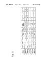
- FIG. 9 is a diagram showing the data stored in the camera parameter table 103 , in the form of a table.
- the contents described in FIG. 9 is as follows, in the sequence starting from the left column of the table. As shown below, the items in the second to the ninth columns in this table show an example of the camera parameters.
- the parameters of a virtual camera are described in the eighth line of the camera parameter table 103 of FIG. 9 .
- the contents indicates that the virtual camera is located at a coordinates (0, y1, 0), that the orientation is 0 degree relative to the Y-Z plane and ⁇ 20 degrees relative to the X-Z plane, that the focal length is f, and that the lens distortion coefficients ⁇ 1 and ⁇ 2 are both zero.
- the virtual camera is a concept introduced in the present invention.
- a prior art image generating apparatus can display only an image obtained by an actually installed camera
- an image generating apparatus in accordance with the present invention permits to obtain an image viewed from the virtual camera located arbitrarily, by calculation using the space reconstructing means 104 and the point-of-view converting means 106 described later in detail. A method of this calculation is also described later in detail.
- the calibrating means 102 in accordance with the present invention performs camera calibration. That is the determination of said camera parameters.
- the methods of the determination include a method in which all the data is manually input directly using an inputting device such as a key board and a mouse, a method in which some of the calibration data is obtained by calculation, and the like.
- the camera parameters are the parameters indicating said camera characteristics, such as a camera attachment position and a camera attachment angle in a reference coordinate system, a camera lens distortion correction value, and a camera lens focal length.
- said parameters can be obtained approximately by calculation.
- a plurality of sets of the points where the correspondence relation between the point in the image shot by the camera and the position of that point within the three-dimensional space coordinate system is established are necessary.
- the minimum number of the required sets depends on the calculation method used. For example, a method of obtaining the camera parameters used in the example of FIG.
- the present invention discloses a method for generating a set of said correspondence relation, thereby obtaining some of the camera parameters by calculation using the set. This method is described later.
- the performing of the lens distortion correction on the camera input image using said lens distortion coefficients needs a lot of calculation, and hence is not suitable for a real-time process.
- the data is retained in a format such as the temperature correction table 111 in accordance with the present invention.
- the calibrating means 102 performs the correction by referencing to the data in said table when a change in the lens distortion occurs due to the rise or fall of the temperature.
- the calibrating means 102 in accordance with the present invention (an example of Claim 14 ) successively observes the temperature value of the temperature sensor 110 of each camera, and renews the contents of the camera parameter table 103 when necessary.
- a temperature sensor 110 is correspondingly attached to each camera as shown in FIG. 3 .
- the temperature sensed by the temperature sensor 110 is assumed to be approximately equal to the lens temperature of the camera.
- FIG. 11 shows an example of a camera parameter table 103 rewritten using the temperature correction table 111 of the example of FIG. 10 .
- the cameras 1 and 2 alone are in a temperature of 40 degrees or higher because of being irradiated by direct sun light and the like. The others keep a temperature from 0 degree less than 40 degrees.
- the camera parameters of the cameras 1 and 2 are changed by the temperature correction process for a temperature of 40 degrees or higher as follows:
- the lenses of all the installed cameras have the same temperature correction characteristics.
- the lenses having the different characteristics are installed.
- the proper table can be used for each camera of the objective of the temperature correction.
- the material of the lenses of said cameras may be made of plastics other than glass, the plastics normally undergoes a vigorous distortion due to the temperature change. However, the problem can be treated by the above-mentioned correction.
- the space reconstructing means 104 in accordance with the present invention generates the space data in which each pixel constituting the image input from a camera is corresponded to a point of the three-dimensional space depending on the camera parameters calculated by the calibrating means 102 . That is, the space reconstructing means 104 calculates where in the three-dimensional space each object included in the image shot by a camera exists, and stores the space data as the calculation result into the space data buffer 105 .
- each pixel constituting the image shot by a camera is expressed by the coordinates on the U-V plane including the CCD imaging plane.
- a calculation formula is necessary which establishes the correspondence of a point of the U-V plane including the image shot by the camera into a point of the world coordinate system.
- FIG. 8 is a conceptual diagram representing an example of the correspondence relation between a point of the U-V coordinate system being set on a plane (plane of view hereafter) including the image shot by a camera and a point of the three-dimensional space coordinate system.
- the correspondence relation is established by the following procedure.
- the above-mentioned two equations can determine the coordinates, in the plane-of-view coordinate system, of each pixel of the image projected onto the plane of view.
- Equation (3) holds among Pe (Xe, Ye, Ze), Pw (Xw, Yw, Zw), (tx, ty, tz), ⁇ , and ⁇ .
- the above-mentioned unknown parameters can be determined by having at least two sets of the points where the correspondence relation between the pixel Pv (u, v) on the plane of view and the coordinates Pw (Xw, Yw, Zw) in the world coordinate system is known.
- the measurement of the coordinates of each set the correspondence relation in which is known contains a positional shift in most cases, which causes an error in the calculation result.
- a method normally used is to solve the simultaneous equations constructed by the measurement of a large number of the sets, by the method of least squares.
- the present process 3. is unnecessary to perform when the camera parameters are previously known.
- the space data in accordance with the present invention is the data in which the correspondence is established by such calculation formulas.
- FIG. 12 shows an example of the description of the space data buffer 105 for storing the space data, in the form of a table.
- the space data buffer 105 stores the correspondence data between a point of a camera image and a point within the space.
- a piece of the space data is described in each line except for the first line.
- Each line, which is the information constituting each space data, includes the following contents.
- V coordinate of the point in the plane-of-view coordinate system including said image
- R color component quantized, for example, in 0-255 gradations
- each of the independent data is stored in the space data buffer 105 .
- An example of this case is the point C of FIGS. 13 to 15 .
- the point C is observed by the two cameras of FIG. 13 , the camera 1 and the camera 2 .
- the information of the correspondence of each pixel of the image shot by each camera into a point of the world coordinate system is stored into the space data buffer 105 in the form of the space data.
- Equation (4) corresponds to the inverse transformation of Equations (1), (2), and (3) described above in detail.
- the Pv (u, v) is calculated using said three equations.
- arbitrary and desired values can be specified for the camera parameters of the camera “tx, ty, tz, ⁇ , ⁇ , and f.” This indicates that the camera can be placed at a desired point of view and at a desired angle. In that case, there occurs a problem how to represent the color of each pixel on the screen projecting the image viewed from the camera placed at said arbitrary point of view.
- 19 is a conceptual diagram showing the situation of the synthesizing of an image viewed from a virtual camera, by point-of-view converting means 106 in accordance with the present invention using the images shot by the car-carried cameras 1 and 2 of FIG. 16 .
- the space data converting means 114 in accordance with the present invention is means necessary when the image generating apparatus described in Claim 1 of the present invention is applied to a vehicle.
- a simple method to resolve the problem is to install a camera also in a lower part of the body of the vehicle.
- the addition of the camera needs an extra cost.
- Said space data converting means 114 of the present invention resolves the problem without the addition of a camera in a lower part of the body of the vehicle or the like. The solution depends on an assumption that the vehicle moves.
- FIG. 23 is a flow chart showing the procedure of the process in space data converting means 114 .
- FIG. 24 is a conceptual diagram used for the assistance of the description of space data converting means 114 .
- FIG. 24 shows the relation between the vehicle positions and the vehicle directions at the starting time (t 1 hereafter) and at the ending time (t 2 hereafter) of a predetermined time duration during the vehicle movement. The procedure of synthesizing the image of the part in a dead angle from the camera is described below with reference to FIGS. 23 and 24 .
- ( 1401 ) Detect the movement distance of the vehicle in a predetermined time duration.
- the movement distance is defined by the straight distance between the vehicle positions at time t 1 and at time t 2 . That is the distance between O 1 and O 2 in FIG. 24 .
- the movement distance from O 1 to O 2 is represented by a vector (t′x, 0, t′z) as shown in FIG. 24 .
- the method used for the detection of the movement distance is, for example, a method by counting the number of revolutions of the wheel.
- the movement direction is defined by the amount of the change which is the difference of the direction of the vehicle at time t 2 from the direction of the vehicle at time t 1 .
- the amount of the change in the direction is represented by the angle ⁇ between the Z1 axis and the Z2 axis as shown in FIG. 24 .
- the method used for the detection of the movement direction is, for example, to measure the rotation angle of the steering wheel or the like.
- Equation (5) for converting the space data acquired at t 1 into the space data at t 2 using the movement distance and the movement direction of the vehicle during the time duration from time t 1 to time t 2 .
- Equation (5) it is assumed that there is perfectly no change in the vertical component in the vehicle movement during the time duration from time t 1 to time t 2 , that is, the road surface is flat.
- Equation (5) convert the space data generated at time t 1 into the space data at time t 2 . Since the generated space data does not need the information which camera is used for viewing, the data in the fifth to the seventh columns in the table of FIG. 12 may be left blank. That is, among the space data at time t 1 , only the first to the fourth columns in the table of FIG. 12 are rewritten, and the data in the eighth to the eleventh columns are used intact.
- a problem is that the overflow in the limited space data buffer 105 will occur some time when the past space data is successively added to the present space data as described above. Since each space data in the space data buffer 105 in accordance with the present invention has the information of the time of the generation of the data, the data prior to a predetermined past time back from the present may be deleted to resolve the problem.
- the characteristic point generating means 109 in accordance with the present invention generates, within the field of view of a camera, a plurality of points the three-dimensional coordinates of which are identifiable.
- the characteristic point extracting means 108 extracts said generated characteristic points.
- FIG. 21 is a conceptual diagram showing an embodiment of the characteristic point generating means 109 , characteristic points, and the characteristic point extracting means 108 .
- FIG. 21( a ) is an embodiment in which a pattern light irradiating apparatus as characteristic point generating means 109 is attached on top of a side of the body of a vehicle.
- rectangle patterns are irradiated in the form of a grid on the road surface as a plane in the world coordinate system, in the surroundings of the vehicle.
- FIG. 21( b ) is an example of the situation that a plurality of the pattern light irradiating apparatuses are attached on top of the body of a vehicle thereby irradiating the pattern light onto the road surface, viewed from top of the vehicle.
- FIG. 21( c ) is an example of the situation that the rectangle pattern light irradiated onto the road surface by such a method is shot by a camera. Certain points, such as the corners and the center of a rectangle generated by the pattern light irradiation, representing the characteristics can be used as the characteristic points.
- the PI- 1 to PI- 8 are the examples of a characteristic point. It is possible to set so that the coordinates of said characteristic points are known in the world coordinate system. Further, the coordinate positions of these characteristic points are also known in the plane-of-view coordinate system, and hence the correspondence relation between the world coordinate system and the plane-of-view coordinate system is established. Accordingly, using the above-mentioned Equations (1), (2), and (3), the calibrating means 102 can calculates the camera parameters tx, ty, tz, ⁇ , ⁇ , and f.
- the correction indicating means in accordance with the present invention is means necessary when the image generating apparatus described in Claim 1 of the present invention is applied to a vehicle.
- the correction indicating means detects a situation requiring the calibration of the camera, and indicates the camera calibration to the driver when the camera calibration is necessary.
- the correction history recording means 115 in accordance with the present invention records the date, time, and running distance when the camera calibration was performed, as the data necessary to detect the situation requiring the camera calibration.
- the camera parameters may be input manually, or calculated by the calibrating means 102 using the result of the extraction of characteristic points by the characteristic point extracting means 108 after the characteristic point generating means 109 in accordance with the present invention generates the characteristic points in the surroundings of the body of the vehicle.
- the space data converting means 114 converts said space data depending on the movement distance and the movement direction of the vehicle.
- the space data buffer 105 is blank, the present process is omitted.
- the space reconstructing means 104 generates the space data in which each pixel constituting the images shot in 5. is corresponded to a point of the world coordinate system.
- the space data of which coordinates in the world coordinate system coincides are present among the space data converted in 4 [sic; 4 ]. by the space data converting means 114 , said converted space data is disposed. That is, only the latest data shot by the camera is retained among the space data of a specific point in the world coordinate system. The data prior to that time and the data of which time has been elapsed in a certain extent are deleted.
- the method is to project the image obtained by a camera of which the attachment position and the attachment angle of which are previously known onto the road surface as an example of a plane constituting a part of the three-dimensional space.
- a camera of which the attachment position and the attachment angle of which are previously known onto the road surface as an example of a plane constituting a part of the three-dimensional space.
- FIG. 27( b ) is a block diagram showing an example of the configuration of an image generating apparatus in accordance with the present invention.
- the configuration is the image generating apparatus shown in FIG. 27( a ) further added obstacle detecting means 108 A for measuring at least the distance to an obstacle existing in the surroundings of the vehicle, as the situation of the surroundings of the vehicle.
- the performing of the lens distortion correction on the camera input image using said lens distortion coefficients needs a lot of calculation, and hence is not suitable for a real-time-process.
- Plane 3 a plane vertical to the road surface (Plane 1 ) on the left side relative to the direction of the traveling of the vehicle
- Plane 4 a plane vertical to the road surface (Plane 1 ) on the rear side
- Plane 5 a plane vertical to the road surface (Plane 1 ) on the right side relative to the direction of the traveling of the vehicle
- Planes 2 to 5 is set without any gap, and hence the image shot by a car-carried camera is mapped any of Planes 1 to 5 .
- the necessary distance from the vehicle and the necessary height can be determined depending on the angle of field and the place of installation of the car-carried camera.
- the space model uses a curved surface of a bowl shape.
- the vehicle is located on the part corresponding to the bottom of the bowl in the space model of the bowl shape.
- the image shot by the car-carried camera is mapped onto the inner surface of the bowl.
- the models of a bowl shape include a sphere, a parabola of revolution, a catenary of revolution, and the like.
- a space model expressed by few equations permitting a fast calculation of the mapping.
- the model of FIG. 28( c ) shows a space model composed of the combination of the plane and the curved surface described below.
- Plane the plane of the road surface (in contact with the wheels)
- Curved surface a wall of cylindrical or elliptic-cylindrical shape placed on said plane so as to surround the vehicle
- the shape of the curved surface and the necessary distance from the vehicle can be determined depending on the angle of field and the place of installation of the car-carried camera.
- Such a space model having a wall in the surroundings of the vehicle so as to surround the vehicle has the following effect. That is, when the camera image is mapped onto the road surface assuming that all the objects in the image are located on the road surface, there has been a problem that an object having a height above the road surface is substantially deformed.
- the vehicle is surrounded by a plane or a curved surface vertical or substantially vertical to the road surface. By setting these surfaces not too far from the vehicle, the object having a height component is mapped onto these surfaces, permitting to reduce the distortion. Further, because of the small distortion in the mapping, the discrepancy in the junction part of the images by two cameras is expected to be small.
- FIG. 29 is a diagram used for the assistance of the description of the mapping of a car-carried camera image onto a surface constituting the space model by converting the coordinates of a point in the U-v coordinate system being set in the plane (called the plane of view hereafter) including the image into the coordinates of a point of the world coordinate system.
- the above-mentioned two equations can determine the coordinates, in the plane-of-view coordinate system, of each pixel of the image projected onto the plane of view.
- Equation (8) holds among Pe (Xe, Ye, Ze), Pw (Xw, Yw, Zw), (tx, ty, tz), and the above-mentioned rotation matrix.
- a pixel Pv (u, v) on the plane of view can be converted to the coordinates Pw (Xw, Yw, Zw) in the world coordinate system.
- each pixel constituting the image shot by the car-carried camera is generally represented by the coordinates on a plane including the image plane.
- the process in the following procedure is performed for all the pixels of the input image.
- FIG. 30 is a flow chart showing the procedure of the mapping process. The contents of the process of the mapping is described below with reference to FIG. 30 .
- the point-of-view converting means 105 A [sic; 105 A] in accordance with the present invention composes an image shot by a camera installed at an arbitrary point of view from the result of the mapping of the car-carried camera image into the space data by the mapping means 104 A [sic; 104 A].
- the outline of the method is to perform the reversed process of the process carried out by the mapping means 104 A [sic; 104 A].
- the car-carried distance sensor can utilize laser light, ultrasonic wave, a stereo optical system, a camera focusing system (the distance from the camera to said object is calculated from the focal length when focused on the objective), and the like.
- the laser light, the ultrasonic wave, or the like is used as the distance sensor 107 A
- a large number of the apparatuses are desirably attached the periphery of the vehicle.
- the stereo optical system or the camera focusing system it may be installed in addition to the car-carried camera, however, use of a part of the car-carried camera permits to reduce the cost.
- the distance from the vehicle in question to an obstacle can be set to be 50 cm to 1 m, from experience.
- the condition to remove the screen plane the following conditions can be used solely or in combination.
- the camera parameter table 102 B is a table for storing the camera parameters. The contents thereof is as described above.
- FIGS. 34( a ) and 34 ( b ) are conceptual diagrams showing a space model in accordance with the present invention.
- an apparatus for monitoring the surroundings of a vehicle in accordance with the present invention composes: movement direction detecting means 109 B for detecting the movement direction of the vehicle; and the movement distance detecting means 108 B for detecting the movement distance of the vehicle in a unit time; and uses the process results of the movement direction detecting means 109 B and the movement distance detecting means 108 B thereby to calculate the present position of said characteristics on the road surface.
- Process 903 Formulate above-mentioned Equation (5) for converting the coordinates of the characteristic point acquired at t 1 into the coordinates of the characteristic point at t 2 using the movement distance and the movement direction of the vehicle during the time duration from time t 1 to time t 2 .
- Equation (5) it is assumed that there is perfectly no change in the vertical component in the vehicle movement during the time duration from time t 1 to time t 2 , that is, the road surface is flat.
- the x1, y1, and z1 represent the coordinates of a point in the X1-Y1-Z1 world coordinate system (the origin O 1 ) based on the vehicle at time t 1
- the x2, y2, and z2 represent the coordinates of said point in the X2-Y2-Z2 world coordinate system (the origin O 2 ) based on the body of the vehicle at time t 2
- the x2, y2, and z2 are the result of the calculation of substituting x1, y1, and z1 into the right hand side of Equation (5).
- Process 904 Using Equation (5), convert the coordinates of the characteristic point synthesized at time t 1 into the coordinates of the characteristic point at time t 2 .
- the characteristics correcting means 110 B While displaying the process result of the road-surface characteristics detecting means 103 B on the displaying means 107 B, the characteristics correcting means 110 B indicates the correction of the characteristics to the crew of the vehicle. The crew corrects the characteristics position on the road surface according to the indication.
- FIG. 39 is a conceptual diagram showing the situation that the characteristics correcting process is displayed on displaying means 107 B.
- FIG. 40 is a flow chart showing the flow of the process in the characteristics correcting process. The procedure of the process of the characteristics correcting means 110 B is described below with reference to these figures.
- Process 1201 Display the present position of the characteristic point on the displaying means 107 B.
- the example of FIG. 39 shows the situation that each image shot by the car-carried camera and the space model are superposed and displayed in a perspectively projected image from above downwardly.
- Process 1202 Specify a characteristic point the position of which is shifted.
- characteristic points 2 and 4 are the shifted points and hence specified.
- the specifying when the displaying apparatus is equipped, for example, with a touch panel, the specification of the place is easily performed by touching the displaying screen with the finger.
- FIG. 41 is a flow chart showing the flow of the overall process of the apparatus for monitoring the surroundings of a vehicle in accordance with the present invention.
- the configuration of FIG. 33( c ) is assumed as the example of the configuration of the apparatus for monitoring the surroundings of a vehicle.
- Process 1301 In order for the present apparatus to operate normally, correct camera parameters for each car-carried camera are previously input into the camera parameter table 102 B.
- Process 1302 Extract a characteristic point on the road surface from the image shot by the car-carried camera.
- Process 1303 Calculate the three-dimensional coordinates of the characteristic point using the within-image coordinates of the extracted characteristic point and the camera parameters.
- the present position of the coordinates of the characteristic point is calculated using the detection result of the movement direction and the movement distance of the vehicle.
- Process 1304 The car-carried camera shots the image of the surroundings of the vehicle.
- Process 1305 The space model generating means 104 B generates a space model based on the image shot in Process 4.
- a Process 1306 The mapping means 105 B maps the image from the car-carried camera into the space model.
- Process 1307 Compose an image viewed from a point of view specified by the driver, by referencing to the image mapped into the space model.
- Process 1308 Display the image synthesized in Process 1307 .
- Process 1310 When shifted, interrupt for the characteristic point correction and perform the process of the characteristic point correction. When the characteristic point correction is unnecessary, return to Process 1303 and repeat the processes. For example, the above-mentioned Processes 1302 to 1309 [sic; 1309 ] are repeated during the driver is trying to park the vehicle in a parking space, and the present processes are terminated on completion of parking.
- the situation of the surroundings of a vehicle in accordance with the present invention includes the condition of the parked vehicles as well as the above-mentioned characteristics on the road surface.
- the space model is generated correspondingly to the condition of the parked vehicles.
- an image viewed from an arbitrary point of view is synthesized using the images from a limited number of cameras.
- a universal space model generated using the characteristics on the road surface obtained from the camera image is introduce instead of a simple plane model.
- the height component is converted to the depth component in the direction of the line of sight, there has been a problem that an object having a height above the road surface is projected onto the road surface with large distortion.
- using the space model in accordance with the present invention even an object having a height is mapped into the space with reduced distortion.
- the discrepancy in the overlap of the images generated by the mapping of said object into the space model is substantially improved in comparison with the plane model, whereby the quality of the image synthesized by the point-of-view conversion is improved.
- the situation of the surroundings is more easily recognizable for the driver with said synthesized image, thereby permitting a suitable driving operation.
- said space model has a simple configuration thereby permitting to reduce the cost of the apparatus.
- An apparatus for image generating apparatus in accordance with the present embodiment has, as the basic configuration, the configuration comprising: a plurality of cameras 101 C attached for grasping the situation of the surroundings of a vehicle; a camera parameter table 102 C for storing the camera parameters indicating the characteristics of cameras 101 C; mapping means 104 C for mapping the images input from the cameras 101 C, into a space model 103 C generated by modeling the situation of the surroundings of the vehicle; point-of-view converting means 105 C for synthesizing a single image viewed from a desired virtual point of view using the data generated by the mapping means 104 C; camera parameter correcting means 106 C for correcting the parameters of the cameras 101 C independently for each camera; and displaying means 107 C for displaying the image converted by the point-of-view converting means 105 C.
- the camera 101 C is a TV camera for shooting an image of a space to be monitored, such as the surroundings of a vehicle.
- FIG. 43( a ) is a conceptual diagram showing an example of three cameras installed on a vehicle.
- the position of the attachment onto the vehicle is a boundary portion between the roof and a side surface or between the roof and the rear surface as shown in FIG. 43( a ) and when the camera used has preferably a large angle of field, a wide field of view is obtained and a smaller number of cameras will do.
- the camera directing backward is installed in each of the right and left door mirror sections and the image from the camera is displayed on a monitor installed in the vehicle, the camera serves as the door mirror. Accordingly, the door mirror can be removed from the vehicle, thereby permitting a car design of excellence in aesthetics as well as aerodynamics.
- the camera parameter table 102 C is a table for storing the camera parameters. The detail thereof is as described above.
- FIG. 44 is a conceptual diagram showing the three-dimensional space coordinate system based on the vehicle.
- a three-dimensional space coordinate system as an example of the three-dimensional space coordinate system is defined by:
- FIG. 46 shows the data stored in a point-of-view parameter table 102 C in the form of a table.
- the items in the second to the tenth [sic; tenth] columns, from left to right, of the contents describe in FIG. 46 show an example of the point-of-view parameters.
- the contents indicates that the virtual point of view is located at a coordinates (0, 0, z2), that the orientation is 0 degree relative to the Y-Z plane, ⁇ 90 degrees relative to the X-Z plane, and no rotation around the optical axis, that the focal length is f 2 , and that the lens distortion coefficients ⁇ 1 and ⁇ 2 are both zero.
- Process 1204 On completion of the correction of the camera in question, write the corrected camera parameters into the camera parameter table 102 C.
- FIG. 60 is a block diagram showing an example of the configuration of an image generating apparatus in accordance with the present invention (an example of Claim 55 ).
- An apparatus for monitoring the surroundings of a vehicle in accordance with the present embodiment has, as the basic configuration, the configuration comprising: a plurality of cameras 101 D attached for grasping the situation of the surroundings of a vehicle; a camera parameter table 102 D for storing the camera parameters indicating the characteristics of cameras 101 D; mapping means 104 D for mapping the images input from the cameras 101 D, into a space model 103 D generated by modeling the situation of the surroundings of the vehicle; a point-of-view parameter table 108 D for storing the point-of-view parameters including at least position and direction; point-of-view converting means 105 D for synthesizing a single image viewed from a desired virtual point of view using the data generated by the mapping means 104 D; point-of-view parameter correcting means 106 D for correcting the parameters of said virtual point of view; and displaying means 107 D for junctioning and displaying the image converted by the point-of-view converting means 105 D.
- the camera 101 D is a TV camera for shooting an image of a space to be monitored, such as the surroundings of a vehicle.
- the camera is attached on the vehicle as shown in FIG. 43 .
- the camera parameter table 102 D is a table for storing the camera parameters.
- the camera parameter is as described above.
- the point-of-view converting means 105 D permits to convert an image shot by the car-carried camera into an image viewed from a desired virtual point of view.
- the image viewed from the virtual point of view is an image which is to be seen if a camera is placed at a desired place and at a desired orientation.
- the point-of-view parameters of the virtual point of view can be expressed by the same camera parameters as described above.
- FIG. 61 is a diagram showing the data stored in the point-of-view parameter table 108 D, in the form of a table.
- the point-of-view parameter table 108 D in the form of a table.
- three sets of the point-of-view parameters are stored, and each set corresponds to each of three car-carried cameras in one-to-one correspondence.
- the image shot by the camera 1 is converted to an image viewed from the virtual point of view 1 by the point-of-view conversion
- the image shot by the camera 2 is converted to an image viewed from the virtual point of view 2 by the point-of-view conversion.
- the space model 103 D is a three-dimensional model where the mapping means 104 D maps the image from the camera into the three-dimensional space coordinate system.
- the model used is, for example, a model consisting of a plane, a curved surface, or a plane and a curved surface.
- a plane model of the road surface is used as an example of the simplest space model 103 D. The method of mapping the image by the car-carried camera into said plane model is described below.
- mapping means 104 C Before the description of the mapping process by the mapping means 104 C, the method for converting the plane-of-view coordinates to the world coordinates is necessary to describe, however, this is the same as described above with regard to FIG. 47 .
- each pixel constituting the image shot by the car-carried camera is generally represented by the coordinates on a plane including the image plane. The detail thereof has been described above in FIG. 47 [sic; FIG. 47 ].
- the point-of-view converting means 105 D composes an image shot by a camera installed at an arbitrary virtual point of view from the result of the mapping of the car-carried camera image into the space data 103 D by the mapping means 104 D.
- the outline of the method has been described above with regard to the point-of-view converting means 105 A.
- FIG. 62 is a conceptual diagram showing the situation that each pixel constituting the input image from a car-carried camera is mapped onto a plane of the space model 103 D by the mapping means 104 D and that an image shot by a camera installed at the virtual point of view is synthesized from the result mapped onto the plane.
- the apparatus comprises:
- the operation of changing the orientation, the position, and the rotation of the virtual point of view is intuitively understandable for the operator when the contents of the operation agrees with the behavior of the image of the operation result.
- the operation direction of the operation of changing the orientation, the position, and the rotation of the virtual point of view is set reverse to the actual change direction of the point-of-view parameters, as is described in Claim 57 of the present invention:
- the direction of the line of sight is moved in the reversed direction of the movement of rod of the joystick 1003 D in the same amount instead that the direction of the moving of the direction of the line of sight is set in the same direction as the movement of rod of the joystick 1003 D.
- the moved state is written into the point-of-view parameter table 102 D, as the altered direction of the line of sight.
- the point-of-view parameter is then set to a value in which the direction of the line of sight is tilted to left by 10 degrees relatively to the current line of sight.
- a conceptual diagram showing a mapping table 109 D in the form of a table has the same contents as FIG. 50 , and hence the detail is omitted.
- the table is composed of the same number of the cells as the number of the pixels of the screen displayed by the displaying means 107 D.
- FIG. 65( a ) is a block diagram showing an example of the configuration of an art relevant to an image generating apparatus in accordance with the present invention.
- FIG. 65( b ) is a conceptual diagram showing an example of a car-carried camera synthesized image before the point-of-view parameter correction.
- FIG. 65( c ) is a conceptual diagram showing an example of a car-carried camera synthesized image after the point-of-view parameter correction.
- the present image generating apparatus has the configuration, in addition to the previous apparatus, further comprising: mapping table correcting means 110 D for re-calculating said mapping table using the point-of-view parameter altered by the process of the point-of-view parameter correcting means; and a buffer 111 D for temporarily storing the data being under the process of the mapping table correcting means 110 D.
- the mapping table correcting means 110 D can alter the contents of the above-mentioned mapping table without performing the complicated calculation of Equation (8), by reflecting the correction result of the point-of-view parameter into Equation (8).
- the method of altering the mapping table is described below sequentially.
- FIGS. 66( a ) to 66 ( c ) are conceptual diagrams used for the assistance of the description of the method of altering the mapping table.
- a gray parallelogram indicates the image plane before the virtual-point-of-view correction
- a white parallelogram indicates the image plane after the virtual-point-of-view correction.
- the configuration of the operating section for the correction of the virtual-point-of-view parameters is assumed to be as shown in FIG. 63 .
- Process 1 Prepare previously the buffer 111 D for temporarily storing the alteration result of the mapping table.
- the cell in which the camera number of the cell coincides with the number of the car-carried camera corresponding to the virtual point of view which is the objective of the correction but in which the correction of the coordinates 1 is not performed is concluded to be out side of the field of view from the virtual point of view in which the correction has been performed.
- coordinate values of the region outside of the display area of the displaying means are written in.
- the displaying means can display a color, such as black, indicating the out-field when undisplayable coordinates are input.
- FIG. 67 is a flow chart showing the flow of the process of correcting the point-of-view parameters in the image generating apparatus of the present invention.
- FIGS. 68( a ) to 68 ( c ) are conceptual diagrams used for the assistance of the description of the process of correcting the point-of-view parameters.
- an image viewed from an arbitrary virtual point of view is synthesized using the images from a limited number of cameras.
- the position and the orientation of the camera are shifted due to vibration and the like during the running of the vehicle, the work to align the shifted image with the other image has been difficult in the prior art because of the prior art uses the method such that the shift is restored by the fine adjustment of the camera itself.
- the image having a shift can be solely corrected by the point-of-view parameter correcting means while watching the image viewed from the virtual point of view as if a camera placed at the point of view is adjusted.
- the corrected state of the movement and the orientation of the point-of-view position are fed back successively as an image. Accordingly, the worker of the correction can obtain the optimal image by checking the display image successively. Therefore, the work of the alignment of the images becomes substantially easy in comparison with the prior art, and a small shift does not require the adjustment of the camera parameters using a large apparatus.
- the camera parameters such as the orientation and the position, of the point of view being virtually set are corrected instead of correcting the orientation of an actual camera.
- the mechanism for changing the orientation of the camera becomes unnecessary, whereby the cost of the apparatus can be reduced.
- An image generating apparatus of the present invention is applicable in the fields of the monitoring of the surroundings of a vehicle, the monitoring of the inside of a shop, and the like, and capable of easily synthesizing a synthesized image having the feeling as if actually viewed from a virtual point of view, using the images shot by respective cameras.
- the apparatus has a feature that a shift in the direction of a camera can be easily corrected in the image.
Abstract
Description
- 101 Camera
- 102 Calibrating means
- 103 Camera parameter table
- 104 Space reconstructing means
- 105 Space data buffer
- 106 Point-of-view converting means
- 107 Displaying means
- 108 Characteristic point extracting means
- 109 Characteristic point generating means
- 110 Temperature sensor
- 111 Temperature correction table
- 112 Movement direction detecting means
- 113 Movement distance detecting means
- 114 Space data converting means
- 115 Correction history recording means
- 116 Camera correction indicating means
- 101A Camera
- 102A Camera parameter table
- 103A Space model generating means
- 104A Mapping means
- 105A Point-of-view converting means
- 106A Displaying means
- 107A Distance sensor
- 108A Obstacle detecting means
- 101B Camera
- 102B Camera parameter table
- 103B Road-surface characteristics detecting means
- 104B Space model generating means
- 105B Mapping means
- 106B Point-of-view converting means
- 107B Displaying means
- 108B Movement distance detecting means
- 109B Movement direction detecting means
- 110B Characteristics correcting means
- 101C Camera
- 102C Camera parameter table
- 103C Space model
- 104C Mapping means
- 105C Point-of-view converting means
- 106C Camera parameter correcting means
- 107C Displaying means
- 108C Mapping table
- 901C Camera selection button
- 902C Parallel displacement button
- 903C Joystick
- 904C Zoom button
- 101D Camera
- 102D Camera parameter table
- 103D Space model
- 104D Mapping means
- 105D Point-of-view converting means
- 106D Point-of-view parameter correcting means
- 107D Displaying means
- 108D Point-of-view parameter table
- 109D Mapping table
- 110D Mapping table correcting means
- 111D Buffer
- 1001D Camera selection button
- 1002D Parallel displacement button
- 1003D Joystick
- 1004D Zoom button
-
- X axis which is the straight line on the road surface just below the rear surface of the vehicle, parallel to the rear surface,
- Y axis which is the axis extending vertically form the road surface in the center of the rear surface of the vehicle, and
- Z axis which is a straight line on the road surface, perpendicular to the rear surface, through the center of the rear surface of the vehicle.
The orientation of the camera in this coordinate system is expressed using α and β defined as follows. - α is the angle relative to the Y-Z plane, and
- β is the angle relative to the X-Z plane.
The three-dimensional space coordinate system, the world coordinate system, and simply, the three-dimensional space hereafter refer to the three-dimensional space coordinate system defined above, unless otherwise mentioned.
-
- lens focal length (the second column in the table),
- lens distortion coefficient κ1 (the third column in the table), and
- lens distortion coefficient κ2 (the fourth column in the table)
due to the temperature. More specific contents shown in the table is as follows.
-
- Add df1 to the present lens focal length.
- Add κ11 to the present lens distortion coefficient.
-
- Add df2 to the present lens focal length.
- Add κ12 to the present lens distortion coefficient.
- Add κ22 to the present lens distortion coefficient.
-
- The lens focal lengths are increased by df1.
- The lens distortion coefficients κ1 are increased by κ12.
- The lens distortion coefficients κ2 [sic; κ2] are increased by κ22.
Since the above-mentioned virtual camera can be assumed to have an ideal lens without any change in focal length and lens distortion due to the temperature, it is not an objective of the correction process.
Now, the correspondence between a pixel Pv (u, v) on the plane of view and the coordinates Pw (Xw, Yw, Zw) in the world coordinate system has been established by Equations (1), (2), and (3).
-
- to mix all the colors in the same ratio,
- to acquire the color having the highest, the lowest, or the middle lightness, and
- to acquire the color having the highest, the lowest, or the middle saturation.
This rotation matrix can be easily obtained by obtaining the rotation matrix around each of the X, Y, and Z axes based on the orientation parameters in the camera parameter table 102A and by making the composition of them.
-
- to mix, in the same ratio, the color already mapped and the color to be mapped,
- to use the color having the higher, the lower, or the middle lightness between the color already mapped and the color to be mapped, and
- to use the color having the higher, the lower, or the middle saturation between the color already mapped and the color to be mapped.
-
- 2-1. Obtain (px0, py0, pz0) from the previously known coordinate values of the
distance sensor 107A. - 2-2. Obtain (px1, py1, pz1) from both the previously known direction (dx, dy, dz) of the
distance sensor 107A and the distance dc to the obstacle. - 2-3. Set the plane (Equation (15)) having the normal vector (dx, dy, dz) and passing through the point (px1, py1, pz1) as the screen plane.
dx(x−px1)+dy(y−py1)+dz(z−pz1)=0 Equation 15
- 2-1. Obtain (px0, py0, pz0) from the previously known coordinate values of the
-
- The distance to the obstacle has become larger than a predetermined distance.
- The driver has initialized the image generating apparatus by any method.
-
- Y coordinate of the characteristic point is estimated from the histogram in the scan in the vertical direction
- X coordinate of the characteristic point is estimated from the histogram in the scan in the horizontal direction
Process 703: Perform the edge extracting process on the image shot by the car-carried camera, then, perform the straight line extracting process on the result of the edge extraction, and estimate a intersecting point or a end point of the obtained straight lines as a characteristic point.FIG. 35( c) shows an example of the process. The edge extraction can be performed, for example, by Sobel operator, and the straight line extraction can be performed, for example, by Hough transformation.
-
- X axis which is the straight line on the road surface just below the rear surface of the vehicle, parallel to the rear surface,
- Y axis which is the axis extending vertically from the road surface in the center of the rear surface of the vehicle, and
- Z axis which is a straight line on the road surface, perpendicular to the rear surface, through the center of the rear surface of the vehicle.
-
- α is the angle relative to the Y-Z plane,
- β is the angle relative to the X-Z plane, and
- γ is the rotation angle around the optical axis of the camera
-
- it may be replaced with a color, such as black, identifiable as a part without an object, or
- the color of the point in question may be interpolated or extrapolated from the periphery points having a mapped color.
-
-
camera selection buttons 901C for selecting a camera to be corrected; - zoom buttons (forward and backward) 904C for moving forward and backward in the direction of the optical axis of the camera;
- parallel displacement buttons (up, down, right, and left) 902C for displacing the camera in parallel to a direction perpendicular to the optical axis of the camera; and
- a
joystick 903C for changing the orientation of the camera and for correcting the rotation around the optical axis of the camera; wherein- (a) the three-dimensional position of the camera can be changed by operating the zoom button 904C and the parallel displacement button 902C, and
- (b) the rotation angle of the camera can be changed by the
joystick 903C, wherein - the following information of the camera parameters is corrected along with the above-mentioned operations (a) and (b):
-
-
- angle β relative to the X-Z plane, among the camera orientation
- rotation angle γ around the optical axis of the camera.
-
- the number of the columns of the table is the horizontal number of the pixels of the display screen; and that
- the number of the lines of the table is the vertical number of the pixels of the display screen.
Each pixel has the data of: - camera number; and
- pixel coordinates of the image shot by said camera. For example, the top left cell of
FIG. 50 indicates the top left or (0, 0) part of the display screen. In response to the data contents (1, 10, 10) stored in said cell, the mapping means 104C performs the process of “displaying the data of the pixel (10, 10) of the image shot by the first camera onto the (0, 0) of the display screen.”
-
- point-of-view selection buttons 1001 for selecting a virtual point of view to be corrected;
- zoom buttons (forward and backward) 1004 for moving forward and backward on the center axis of the line of sight from the virtual point of view;
- parallel displacement buttons (up, down, right, and left relative to an image plane) 1002 for displacing the virtual point of view in parallel to a direction perpendicular to the line of sight from the point of view; and
- a joystick 1003D for changing the direction of the line of sight from the virtual point of view and for correcting the rotation around the direction of the line of sight from the virtual point of view; wherein
- (a) the three-dimensional position of the virtual point of view can be changed by operating the zoom button 1004D and the parallel displacement button 1002D, and
- (b) the direction of the line of sight from the virtual point of view can be changed by the joystick 1003D, wherein
- the following information of the virtual-point-of-view parameters in question is corrected and overwritten on the point-of-view parameter table 108D along with the above-mentioned operations (a) and (b):
- (a) X, Y, and Z coordinates of the virtual-point-of-view position in the three-dimensional space coordinate system
- (b) angle α relative to the Y-Z plane, among the direction of the line of sight from the virtual point of view
- angle β relative to the X-Z plane, among the direction of the line of sight from the virtual point of view
- rotation angle β around the center axis of the line of sight from the virtual point of view.
P 1:(u 1 ,v 1)→P′ 1:(u′ 1 ,v′ 1)=(u 1 =du,v 1 −dv) Equation 10
P 4: (u,v 4)→P′ 4:(u′ 4 ,v′ 4)=(k·u 4 ,k·u 4) Equation 14
Process 3: Alter the mapping table by referring to the
Claims (61)
Applications Claiming Priority (6)
| Application Number | Priority Date | Filing Date | Title |
|---|---|---|---|
| JP21726198 | 1998-07-31 | ||
| JP28623398 | 1998-10-08 | ||
| JP31740798 | 1998-11-09 | ||
| JP31739398 | 1998-11-09 | ||
| JP32470198 | 1998-11-16 | ||
| PCT/JP1999/004061 WO2000007373A1 (en) | 1998-07-31 | 1999-07-29 | Method and apparatus for displaying image |
Publications (1)
| Publication Number | Publication Date |
|---|---|
| US7307655B1 true US7307655B1 (en) | 2007-12-11 |
Family
ID=27529636
Family Applications (1)
| Application Number | Title | Priority Date | Filing Date |
|---|---|---|---|
| US09/744,787 Expired - Lifetime US7307655B1 (en) | 1998-07-31 | 1999-07-29 | Method and apparatus for displaying a synthesized image viewed from a virtual point of view |
Country Status (4)
| Country | Link |
|---|---|
| US (1) | US7307655B1 (en) |
| EP (4) | EP2259220A3 (en) |
| JP (1) | JP3286306B2 (en) |
| WO (1) | WO2000007373A1 (en) |
Cited By (177)
| Publication number | Priority date | Publication date | Assignee | Title |
|---|---|---|---|---|
| US20050082462A1 (en) * | 2003-10-20 | 2005-04-21 | Nissan Motor Co., Ltd. | Image pickup device |
| US20060203092A1 (en) * | 2000-04-28 | 2006-09-14 | Matsushita Electric Industrial Co., Ltd. | Image processor and monitoring system |
| US20060265442A1 (en) * | 2003-10-01 | 2006-11-23 | Saju Palayur | Method and system for controlling a user interface a corresponding device and software devices for implementing the method |
| US20070041659A1 (en) * | 2005-02-15 | 2007-02-22 | Kunio Nobori | Surroundings monitoring apparatus and surroundings monitoring method |
| US20070057816A1 (en) * | 2005-09-12 | 2007-03-15 | Aisin Aw Co., Ltd. | Parking assist method and parking assist apparatus |
| US20070070197A1 (en) * | 2005-09-28 | 2007-03-29 | Nissan Motor Co., Ltd. | Vehicle periphery video providing apparatus and method |
| US20070081262A1 (en) * | 2005-10-07 | 2007-04-12 | Nissan Motor Co., Ltd. | Blind spot image display apparatus and method thereof for vehicle |
| US20070120656A1 (en) * | 2004-04-27 | 2007-05-31 | Tomoya Nakanishi | Vehicle surrounding display device |
| US20070132863A1 (en) * | 2005-12-14 | 2007-06-14 | Sony Corporation | Image taking apparatus, image processing method, and image processing program |
| US20070165108A1 (en) * | 2005-11-30 | 2007-07-19 | Mizuki Yuasa | Vehicle Surrounding Image Display Device |
| US20070247525A1 (en) * | 2004-06-01 | 2007-10-25 | L-3 Comminications Corporation | Video Flashlight/Vision Alert |
| US20080012866A1 (en) * | 2006-07-16 | 2008-01-17 | The Jim Henson Company | System and method of producing an animated performance utilizing multiple cameras |
| US20080043113A1 (en) * | 2006-08-21 | 2008-02-21 | Sanyo Electric Co., Ltd. | Image processor and visual field support device |
| US20080162004A1 (en) * | 2006-12-27 | 2008-07-03 | Price Robert J | Machine control system and method |
| US20080291275A1 (en) * | 2005-10-12 | 2008-11-27 | Valeo Etudes Electroniques | Video Data Processor Device for a Motor Vehicle |
| US20090092334A1 (en) * | 2003-08-09 | 2009-04-09 | Doubleshot, Inc. | Birds eye view virtual imaging for real time composited wide field of view |
| US20090102950A1 (en) * | 2003-05-02 | 2009-04-23 | Yavuz Ahiska | Multiple-View Processing in Wide-Angle Video Camera |
| US20090141148A1 (en) * | 2007-12-04 | 2009-06-04 | Kosuke Imamura | Distortion-corrected image generation unit and distortion-corrected image generation method |
| US20090194008A1 (en) * | 2008-01-24 | 2009-08-06 | Brother Kogyo Kabushiki Kaisha | Sewing machine and computer-readable medium storing control program executable on sewing machine |
| US20090201361A1 (en) * | 2008-02-08 | 2009-08-13 | Google Inc. | Panoramic Camera With Multiple Image Sensors Using Timed Shutters |
| US20100013927A1 (en) * | 2008-04-11 | 2010-01-21 | Nearmap Pty Ltd. | Systems and Methods of Capturing Large Area Images in Detail Including Cascaded Cameras and/or Calibration Features |
| US20100054580A1 (en) * | 2004-03-11 | 2010-03-04 | Olympus Corporation | Image generation device, image generation method, and image generation program |
| EP2192552A1 (en) | 2008-11-28 | 2010-06-02 | Fujitsu Limited | Image processing apparatus, image processing method, and recording medium |
| US20100165104A1 (en) * | 2006-03-27 | 2010-07-01 | Sanyo Electric Co., Ltd. | Drive Assistance Device |
| US20100201810A1 (en) * | 2007-10-19 | 2010-08-12 | Kabushiki Kaisha Toyota Jidoshokki | Image display apparatus and image display method |
| US20100214412A1 (en) * | 2007-10-16 | 2010-08-26 | Daimler Ag | Method for calibrating an assembly using at least one omnidirectional camera and an optical display unit |
| US20100245607A1 (en) * | 2009-03-31 | 2010-09-30 | Fujitsu Limited | Video processing apparatus |
| US20100245573A1 (en) * | 2009-03-25 | 2010-09-30 | Fujitsu Limited | Image processing method and image processing apparatus |
| US20100259371A1 (en) * | 2009-04-10 | 2010-10-14 | Jui-Hung Wu | Bird-View Parking Aid Apparatus with Ultrasonic Obstacle Marking and Method of Maneuvering the same |
| US20100271481A1 (en) * | 2009-04-23 | 2010-10-28 | Sanyo Electric Co., Ltd. | Maneuver Assisting Apparatus |
| US20110001826A1 (en) * | 2008-03-19 | 2011-01-06 | Sanyo Electric Co., Ltd. | Image processing device and method, driving support system, and vehicle |
| US20110013021A1 (en) * | 2008-03-19 | 2011-01-20 | Sanyo Electric Co., Ltd. | Image processing device and method, driving support system, and vehicle |
| US20110032357A1 (en) * | 2008-05-29 | 2011-02-10 | Fujitsu Limited | Vehicle image processing apparatus and vehicle image processing method |
| EP2295277A1 (en) | 2009-09-15 | 2011-03-16 | Delphi Technologies, Inc. | Vehicle operator control input assistance |
| US7912283B1 (en) * | 2007-10-31 | 2011-03-22 | The United States Of America As Represented By The Secretary Of The Air Force | Image enhancement using object profiling |
| US7920959B1 (en) * | 2005-05-01 | 2011-04-05 | Christopher Reed Williams | Method and apparatus for estimating the velocity vector of multiple vehicles on non-level and curved roads using a single camera |
| US20110096956A1 (en) * | 2008-06-12 | 2011-04-28 | Honda Motor Co., Ltd. | Vehicle periphery monitoring device |
| US20110187816A1 (en) * | 2008-11-05 | 2011-08-04 | Fujitsu Limited | Camera angle computing device and camera angle computing method |
| US20110227916A1 (en) * | 2005-03-10 | 2011-09-22 | Nintendo Co., Ltd. | Storage medium storing game program and game apparatus |
| US20110234802A1 (en) * | 2010-03-25 | 2011-09-29 | Fujitsu Ten Limited | On-vehicle lighting apparatus |
| US20120069187A1 (en) * | 2009-05-29 | 2012-03-22 | Fujitsu Ten Limited | Image generating apparatus and image display system |
| US20120069153A1 (en) * | 2009-05-25 | 2012-03-22 | Panasonic Corporation | Device for monitoring area around vehicle |
| US20120105642A1 (en) * | 2009-06-29 | 2012-05-03 | Panasonic Corporation | Vehicle-mounted video display device |
| CN102469291A (en) * | 2010-11-05 | 2012-05-23 | 屈世虎 | Video call system and method |
| WO2012075250A1 (en) * | 2010-12-01 | 2012-06-07 | Magna Electronics Inc. | System and method of establishing a multi-camera image using pixel remapping |
| US20120188267A1 (en) * | 2010-06-08 | 2012-07-26 | Panasonic Corporation | Method of generating inverse conversion table, program for generating inverse conversion table, image conversion device, image conversion method, and image conversion program |
| US8238695B1 (en) * | 2005-12-15 | 2012-08-07 | Grandeye, Ltd. | Data reduction techniques for processing wide-angle video |
| US20120262580A1 (en) * | 2011-04-14 | 2012-10-18 | Klaus Huebner | Vehicle Surround View System |
| CN102792684A (en) * | 2010-04-12 | 2012-11-21 | 住友重机械工业株式会社 | Image generation device and operation support system |
| CN102792685A (en) * | 2010-04-12 | 2012-11-21 | 住友重机械工业株式会社 | Processing target image generation device, processing target image generation method, and operation support system |
| CN102792334A (en) * | 2010-04-12 | 2012-11-21 | 住友重机械工业株式会社 | Image generation device and operation support system |
| WO2012171138A1 (en) * | 2011-06-14 | 2012-12-20 | Metrologic Instruments, Inc. | Camera registration and video integration in 3-d geometry model |
| US20130011020A1 (en) * | 2011-07-06 | 2013-01-10 | Morpho, Inc. | Image processing device, image processing method and storage medium |
| WO2013016409A1 (en) * | 2011-07-26 | 2013-01-31 | Magna Electronics Inc. | Vision system for vehicle |
| US20130033495A1 (en) * | 2010-04-12 | 2013-02-07 | Sumitomo Heavy Industries, Ltd. | Image generation device and operation support system |
| US20130033602A1 (en) * | 2011-08-05 | 2013-02-07 | Harman Becker Automotive Systems Gmbh | Surround View System |
| US20130050401A1 (en) * | 2009-09-04 | 2013-02-28 | Breitblick Gmbh | Portable wide-angle video recording system |
| US20130208081A1 (en) * | 2012-02-13 | 2013-08-15 | Omnivision Technologies, Inc. | Method for combining images |
| DE102012203171A1 (en) * | 2012-02-29 | 2013-08-29 | Bayerische Motoren Werke Aktiengesellschaft | Method for processing image data of images captured by cameras arranged on e.g. car, involves determining image data onto surface of environment model based on preset position of virtual camera and environment model image data |
| CN103303198A (en) * | 2012-03-07 | 2013-09-18 | 株式会社电装 | Vehicle circumference monitor device |
| US20130253796A1 (en) * | 2012-03-26 | 2013-09-26 | Robert Bosch Gmbh | Multi-surface model-based tracking |
| US20130293683A1 (en) * | 2012-05-03 | 2013-11-07 | Harman International (Shanghai) Management Co., Ltd. | System and method of interactively controlling a virtual camera |
| US20140055487A1 (en) * | 2012-08-21 | 2014-02-27 | Fujitsu Ten Limited | Image generator |
| US8675068B2 (en) | 2008-04-11 | 2014-03-18 | Nearmap Australia Pty Ltd | Systems and methods of capturing large area images in detail including cascaded cameras and/or calibration features |
| EP2711895A2 (en) | 2012-09-24 | 2014-03-26 | Clarion Co., Ltd. | Calibration method and apparatus for in-vehicle camera |
| JP2014085925A (en) * | 2012-10-25 | 2014-05-12 | Fujitsu Ltd | Image processing apparatus, method, and program |
| US20140139640A1 (en) * | 2011-07-29 | 2014-05-22 | Fujitsu Limited | Image processing apparatus, image processing method, and computer-readable recording medium |
| US8768583B2 (en) | 2012-03-29 | 2014-07-01 | Harnischfeger Technologies, Inc. | Collision detection and mitigation systems and methods for a shovel |
| US8773534B2 (en) | 2009-04-13 | 2014-07-08 | Fujitsu Limited | Image processing apparatus, medium recording image processing program, and image processing method |
| US20140204201A1 (en) * | 2013-01-21 | 2014-07-24 | Devin L. Norman | External Vehicle Projection System |
| US20140233808A1 (en) * | 2013-02-15 | 2014-08-21 | Gordon Peckover | Method of measuring road markings |
| US8872889B2 (en) | 2010-01-14 | 2014-10-28 | Innovmetric Logiciels Inc. | Synchronization of the orientation of a 3D measurement device and the orientation of an intelligent guidance device |
| US20140347450A1 (en) * | 2011-11-30 | 2014-11-27 | Imagenext Co., Ltd. | Method and apparatus for creating 3d image of vehicle surroundings |
| US20140375812A1 (en) * | 2011-10-14 | 2014-12-25 | Robert Bosch Gmbh | Method for representing a vehicle's surrounding environment |
| US8934017B2 (en) | 2011-06-01 | 2015-01-13 | Honeywell International Inc. | System and method for automatic camera placement |
| US20150016680A1 (en) * | 2012-04-13 | 2015-01-15 | Lightcraft Technology, Llc | Hybrid precision tracking |
| US20150022669A1 (en) * | 2013-07-17 | 2015-01-22 | Microsoft Corporation | Real-time registration of a stereo depth camera array |
| US8947533B2 (en) | 2010-01-22 | 2015-02-03 | Fujitsu Ten Limited | Parameter determining device, parameter determining system, parameter determining method, and recording medium |
| US20150070498A1 (en) * | 2013-09-06 | 2015-03-12 | Caterpillar Inc. | Image Display System |
| TWI484449B (en) * | 2012-07-03 | 2015-05-11 | ||
| US9030561B2 (en) | 2010-06-29 | 2015-05-12 | Clarion Co., Ltd. | Image calibration method and image calibration device |
| US20150170520A1 (en) * | 2013-11-29 | 2015-06-18 | Hyundai Mobis Co., Ltd. | Parking guide line device and displaying method |
| US9064293B2 (en) | 2010-06-15 | 2015-06-23 | Mitsubishi Electric Corporation | Vehicle surroundings monitoring device |
| US20150178884A1 (en) * | 2013-12-19 | 2015-06-25 | Kay-Ulrich Scholl | Bowl-shaped imaging system |
| US20150175161A1 (en) * | 2002-04-09 | 2015-06-25 | Intelligent Technologies International, Inc. | Exterior Monitoring for Vehicles |
| DE102013226632A1 (en) * | 2013-12-19 | 2015-06-25 | Conti Temic Microelectronic Gmbh | Camera system and method for operating a camera system |
| US20150197900A1 (en) * | 2012-11-08 | 2015-07-16 | Sumitomo Heavy Industries, Ltd. | Image generating apparatus for paving machine and operation support system for paving machine |
| US9098751B2 (en) | 2011-07-27 | 2015-08-04 | Gentex Corporation | System and method for periodic lane marker identification and tracking |
| US20150242694A1 (en) * | 2012-09-14 | 2015-08-27 | Honda Motor Co., Ltd. | Object identifier |
| US20150249822A1 (en) * | 2012-10-01 | 2015-09-03 | Bodybarista Aps | Method of calibrating a camera |
| US9143670B1 (en) * | 2012-07-20 | 2015-09-22 | COPsync, Inc. | Video capture system including two independent image sensors |
| US20150343976A1 (en) * | 2012-12-24 | 2015-12-03 | Doosan Infracore Co., Ltd. | Sensing device and method of construction equipment |
| US20160035110A1 (en) * | 2013-04-24 | 2016-02-04 | Sumitomo Heavy Industries, Ltd. | Processing-target image creating device, processing-target image creating method, and operation assisting system |
| WO2016037014A1 (en) * | 2014-09-03 | 2016-03-10 | Nextvr Inc. | Methods and apparatus for capturing, streaming and/or playing back content |
| US9315192B1 (en) * | 2013-09-30 | 2016-04-19 | Google Inc. | Methods and systems for pedestrian avoidance using LIDAR |
| WO2013086249A3 (en) * | 2011-12-09 | 2016-05-19 | Magna Electronics, Inc. | Vehicle vision system with customized display |
| US9361687B2 (en) | 2011-06-13 | 2016-06-07 | Alpine Electronics, Inc. | Apparatus and method for detecting posture of camera mounted on vehicle |
| US9386302B2 (en) * | 2014-05-21 | 2016-07-05 | GM Global Technology Operations LLC | Automatic calibration of extrinsic and intrinsic camera parameters for surround-view camera system |
| US20160193983A1 (en) * | 2013-10-11 | 2016-07-07 | Fujitsu Ten Limited | Image display device, image display system, image display method and program |
| US9387804B2 (en) * | 2014-01-03 | 2016-07-12 | Hyundai Mobis Co., Ltd. | Image distortion compensating apparatus and operating method thereof |
| EP2464113A4 (en) * | 2009-08-03 | 2016-11-16 | Aisin Seiki | Vehicle peripheral image generation device |
| CN106204521A (en) * | 2015-06-01 | 2016-12-07 | 东芝阿尔派·汽车技术有限公司 | Eye view image generating means |
| DE10296593B4 (en) * | 2001-03-28 | 2017-02-02 | Panasonic Intellectual Property Management Co., Ltd. | Driving support device |
| EP3132974A1 (en) * | 2015-08-20 | 2017-02-22 | LG Electronics Inc. | Display apparatus and vehicle including the same |
| US20170109940A1 (en) * | 2015-10-14 | 2017-04-20 | Qualcomm Incorporated | Systems and methods for producing an image visualization |
| US9902341B2 (en) | 2014-02-26 | 2018-02-27 | Kyocera Corporation | Image processing apparatus and image processing method including area setting and perspective conversion |
| US20180067488A1 (en) * | 2016-09-08 | 2018-03-08 | Mentor Graphics Corporation | Situational awareness determination based on an annotated environmental model |
| CN107852483A (en) * | 2015-08-04 | 2018-03-27 | 株式会社电装 | The devices and methods therefor of assistant images is prompted to driver |
| US10046700B2 (en) | 2012-05-22 | 2018-08-14 | Mitsubishi Electric Corporation | Image processing device |
| US10127463B2 (en) | 2014-11-21 | 2018-11-13 | Magna Electronics Inc. | Vehicle vision system with multiple cameras |
| US10187590B2 (en) | 2015-10-27 | 2019-01-22 | Magna Electronics Inc. | Multi-camera vehicle vision system with image gap fill |
| US20190026924A1 (en) * | 2016-01-15 | 2019-01-24 | Nokia Technologies Oy | Method and Apparatus for Calibration of a Multi-Camera System |
| US20190088006A1 (en) * | 2017-09-15 | 2019-03-21 | Aisin Seiki Kabushiki Kaisha | Image processing device |
| US10308179B2 (en) | 2015-10-30 | 2019-06-04 | Conti Temic Microelectronic Gmbh | Device and method for providing a vehicle surround view |
| US10313584B2 (en) * | 2017-01-04 | 2019-06-04 | Texas Instruments Incorporated | Rear-stitched view panorama for rear-view visualization |
| US10326979B2 (en) | 2016-05-23 | 2019-06-18 | Microsoft Technology Licensing, Llc | Imaging system comprising real-time image registration |
| US10339662B2 (en) | 2016-05-23 | 2019-07-02 | Microsoft Technology Licensing, Llc | Registering cameras with virtual fiducials |
| US10373378B2 (en) | 2015-06-26 | 2019-08-06 | Paccar Inc | Augmented reality system for vehicle blind spot prevention |
| US10384605B1 (en) | 2018-09-04 | 2019-08-20 | Ford Global Technologies, Llc | Methods and apparatus to facilitate pedestrian detection during remote-controlled maneuvers |
| US10442355B2 (en) | 2014-09-17 | 2019-10-15 | Intel Corporation | Object visualization in bowl-shaped imaging systems |
| US10452076B2 (en) | 2017-01-04 | 2019-10-22 | Magna Electronics Inc. | Vehicle vision system with adjustable computation and data compression |
| US10484665B2 (en) | 2017-04-20 | 2019-11-19 | Panasonic Intellectual Property Management Co., Ltd. | Camera parameter set calculation method, recording medium, and camera parameter set calculation apparatus |
| US10493981B2 (en) | 2018-04-09 | 2019-12-03 | Ford Global Technologies, Llc | Input signal management for vehicle park-assist |
| US10507868B2 (en) | 2018-02-22 | 2019-12-17 | Ford Global Technologies, Llc | Tire pressure monitoring for vehicle park-assist |
| CN110619807A (en) * | 2018-06-20 | 2019-12-27 | 北京京东尚科信息技术有限公司 | Method and device for generating global thermodynamic diagram |
| US10529233B1 (en) | 2018-09-24 | 2020-01-07 | Ford Global Technologies Llc | Vehicle and method for detecting a parking space via a drone |
| US10562452B2 (en) | 2010-04-19 | 2020-02-18 | SMR Patents S.à.r.l. | Rear-view mirror simulation |
| US10580304B2 (en) | 2017-10-02 | 2020-03-03 | Ford Global Technologies, Llc | Accelerometer-based external sound monitoring for voice controlled autonomous parking |
| US10578676B2 (en) | 2017-11-28 | 2020-03-03 | Ford Global Technologies, Llc | Vehicle monitoring of mobile device state-of-charge |
| US10583830B2 (en) | 2018-01-02 | 2020-03-10 | Ford Global Technologies, Llc | Mobile device tethering for a remote parking assist system of a vehicle |
| US10585430B2 (en) | 2017-06-16 | 2020-03-10 | Ford Global Technologies, Llc | Remote park-assist authentication for vehicles |
| US10585431B2 (en) | 2018-01-02 | 2020-03-10 | Ford Global Technologies, Llc | Mobile device tethering for a remote parking assist system of a vehicle |
| US10627811B2 (en) | 2017-11-07 | 2020-04-21 | Ford Global Technologies, Llc | Audio alerts for remote park-assist tethering |
| US10628687B1 (en) | 2018-10-12 | 2020-04-21 | Ford Global Technologies, Llc | Parking spot identification for vehicle park-assist |
| US20200137379A1 (en) * | 2017-06-27 | 2020-04-30 | Sony Corporation | Image processing device, image processing method, and program |
| US10645365B2 (en) | 2017-05-01 | 2020-05-05 | Panasonic Intellectual Property Management Co., Ltd. | Camera parameter set calculation apparatus, camera parameter set calculation method, and recording medium |
| US10659677B2 (en) | 2017-07-21 | 2020-05-19 | Panasonic Intellectual Property Managment Co., Ltd. | Camera parameter set calculation apparatus, camera parameter set calculation method, and recording medium |
| US10684627B2 (en) | 2018-02-06 | 2020-06-16 | Ford Global Technologies, Llc | Accelerometer-based external sound monitoring for position aware autonomous parking |
| US10683034B2 (en) * | 2017-06-06 | 2020-06-16 | Ford Global Technologies, Llc | Vehicle remote parking systems and methods |
| US10683004B2 (en) | 2018-04-09 | 2020-06-16 | Ford Global Technologies, Llc | Input signal management for vehicle park-assist |
| US10684773B2 (en) | 2018-01-03 | 2020-06-16 | Ford Global Technologies, Llc | Mobile device interface for trailer backup-assist |
| US10688918B2 (en) | 2018-01-02 | 2020-06-23 | Ford Global Technologies, Llc | Mobile device tethering for a remote parking assist system of a vehicle |
| US10703299B2 (en) | 2010-04-19 | 2020-07-07 | SMR Patents S.à.r.l. | Rear view mirror simulation |
| US10706292B2 (en) | 2016-03-07 | 2020-07-07 | Denso Corporation | Information processing apparatus and program |
| US10717432B2 (en) | 2018-09-13 | 2020-07-21 | Ford Global Technologies, Llc | Park-assist based on vehicle door open positions |
| US10732622B2 (en) | 2018-04-05 | 2020-08-04 | Ford Global Technologies, Llc | Advanced user interaction features for remote park assist |
| US10737690B2 (en) | 2018-01-02 | 2020-08-11 | Ford Global Technologies, Llc | Mobile device tethering for a remote parking assist system of a vehicle |
| US10737624B2 (en) | 2017-03-24 | 2020-08-11 | Toyota Jidosha Kabushiki Kaisha | Viewing device for vehicle |
| US10747218B2 (en) | 2018-01-12 | 2020-08-18 | Ford Global Technologies, Llc | Mobile device tethering for remote parking assist |
| US10759417B2 (en) | 2018-04-09 | 2020-09-01 | Ford Global Technologies, Llc | Input signal management for vehicle park-assist |
| US10775781B2 (en) | 2017-06-16 | 2020-09-15 | Ford Global Technologies, Llc | Interface verification for vehicle remote park-assist |
| US10793144B2 (en) | 2018-04-09 | 2020-10-06 | Ford Global Technologies, Llc | Vehicle remote park-assist communication counters |
| US10814864B2 (en) | 2018-01-02 | 2020-10-27 | Ford Global Technologies, Llc | Mobile device tethering for a remote parking assist system of a vehicle |
| US10821972B2 (en) | 2018-09-13 | 2020-11-03 | Ford Global Technologies, Llc | Vehicle remote parking assist systems and methods |
| US10875452B2 (en) | 2016-01-12 | 2020-12-29 | Denso Corporation | Driving assistance device and driving assistance method |
| CN112208438A (en) * | 2019-07-10 | 2021-01-12 | 中华汽车工业股份有限公司 | Driving auxiliary image generation method and system |
| US10908603B2 (en) | 2018-10-08 | 2021-02-02 | Ford Global Technologies, Llc | Methods and apparatus to facilitate remote-controlled maneuvers |
| US10917748B2 (en) | 2018-01-25 | 2021-02-09 | Ford Global Technologies, Llc | Mobile device tethering for vehicle systems based on variable time-of-flight and dead reckoning |
| US10967851B2 (en) | 2018-09-24 | 2021-04-06 | Ford Global Technologies, Llc | Vehicle system and method for setting variable virtual boundary |
| US10974717B2 (en) | 2018-01-02 | 2021-04-13 | Ford Global Technologies, I.LC | Mobile device tethering for a remote parking assist system of a vehicle |
| US11056001B2 (en) | 2016-06-07 | 2021-07-06 | Panasonic Intellectual Property Management Co., Ltd. | Image generating apparatus, image generating method, and recording medium |
| US11082684B2 (en) * | 2017-08-25 | 2021-08-03 | Socionext Inc. | Information processing apparatus and recording medium |
| US11097723B2 (en) | 2018-10-17 | 2021-08-24 | Ford Global Technologies, Llc | User interfaces for vehicle remote park assist |
| US11137754B2 (en) | 2018-10-24 | 2021-10-05 | Ford Global Technologies, Llc | Intermittent delay mitigation for remote vehicle operation |
| US11138702B2 (en) * | 2018-12-17 | 2021-10-05 | Canon Kabushiki Kaisha | Information processing apparatus, information processing method and non-transitory computer readable storage medium |
| US11148661B2 (en) | 2018-01-02 | 2021-10-19 | Ford Global Technologies, Llc | Mobile device tethering for a remote parking assist system of a vehicle |
| US11169517B2 (en) | 2019-04-01 | 2021-11-09 | Ford Global Technologies, Llc | Initiation of vehicle remote park-assist with key fob |
| US11188070B2 (en) | 2018-02-19 | 2021-11-30 | Ford Global Technologies, Llc | Mitigating key fob unavailability for remote parking assist systems |
| US11195415B2 (en) * | 2017-10-13 | 2021-12-07 | Waymo Llc | Lane change notification |
| US11195344B2 (en) | 2019-03-15 | 2021-12-07 | Ford Global Technologies, Llc | High phone BLE or CPU burden detection and notification |
| US11227429B2 (en) * | 2018-06-11 | 2022-01-18 | Canon Kabushiki Kaisha | Image processing apparatus, method and storage medium for generating a virtual viewpoint with reduced image data |
| US11275368B2 (en) | 2019-04-01 | 2022-03-15 | Ford Global Technologies, Llc | Key fobs for vehicle remote park-assist |
| US11282392B2 (en) * | 2018-02-16 | 2022-03-22 | Renault S.A.S | Method for monitoring an environment of a parked motor vehicle comprising an asynchronous camera |
| EP4016459A1 (en) * | 2020-12-17 | 2022-06-22 | 6 River Systems, LLC | Systems and methods for calibrating sensors of autonomous vehicles |
| US20220203894A1 (en) * | 2020-12-28 | 2022-06-30 | Samsung Electro-Mechanics Co., Ltd. | Vehicle svm system including tilt camera |
| US11394926B2 (en) | 2016-08-12 | 2022-07-19 | Denso Corporation | Periphery monitoring apparatus |
| US11789442B2 (en) | 2019-02-07 | 2023-10-17 | Ford Global Technologies, Llc | Anomalous input detection |
Families Citing this family (122)
| Publication number | Priority date | Publication date | Assignee | Title |
|---|---|---|---|---|
| US6822563B2 (en) | 1997-09-22 | 2004-11-23 | Donnelly Corporation | Vehicle imaging system with accessory control |
| US6891563B2 (en) | 1996-05-22 | 2005-05-10 | Donnelly Corporation | Vehicular vision system |
| JP3655119B2 (en) * | 1999-03-09 | 2005-06-02 | 株式会社東芝 | Status information providing apparatus and method |
| DE10037128A1 (en) * | 1999-09-13 | 2001-05-03 | Volkswagen Ag | Method and device for inspecting a vehicle driving path uses a camera linked to a lens or a lens system with electrically adjustable or panning devices for altering focal length and viewing direction of the camera's current position. |
| JP3624769B2 (en) * | 1999-09-30 | 2005-03-02 | 株式会社豊田自動織機 | Image conversion device for vehicle rear monitoring device |
| US6542840B2 (en) | 2000-01-27 | 2003-04-01 | Matsushita Electric Industrial Co., Ltd. | Calibration system, target apparatus and calibration method |
| JP4439668B2 (en) * | 2000-03-31 | 2010-03-24 | パナソニック株式会社 | Image synthesizer |
| DE60105684T2 (en) | 2000-04-05 | 2005-02-10 | Matsushita Electric Industrial Co., Ltd., Kadoma | System and method for driver assistance |
| JP3606816B2 (en) * | 2000-04-05 | 2005-01-05 | 松下電器産業株式会社 | Driving assistance device |
| JP3552212B2 (en) * | 2000-05-24 | 2004-08-11 | 松下電器産業株式会社 | Drawing equipment |
| JP4537537B2 (en) * | 2000-05-25 | 2010-09-01 | パナソニック株式会社 | Driving assistance device |
| JP2001334869A (en) * | 2000-05-25 | 2001-12-04 | Matsushita Electric Ind Co Ltd | Driving support system |
| JP3599639B2 (en) | 2000-05-26 | 2004-12-08 | 松下電器産業株式会社 | Image processing device |
| JP4433575B2 (en) * | 2000-06-16 | 2010-03-17 | 株式会社豊田中央研究所 | In-vehicle imaging device |
| JP3830025B2 (en) * | 2000-06-30 | 2006-10-04 | 松下電器産業株式会社 | Drawing device |
| JP3625059B2 (en) * | 2000-06-30 | 2005-03-02 | 松下電器産業株式会社 | Drawing device |
| EP1168248A3 (en) | 2000-06-30 | 2003-12-10 | Matsushita Electric Industrial Co., Ltd. | Rendering device |
| JP3269056B2 (en) * | 2000-07-04 | 2002-03-25 | 松下電器産業株式会社 | Monitoring system |
| JP4156181B2 (en) * | 2000-07-12 | 2008-09-24 | 日産自動車株式会社 | Parking assistance device |
| JP3372944B2 (en) * | 2000-07-19 | 2003-02-04 | 松下電器産業株式会社 | Monitoring system |
| JP3753681B2 (en) * | 2000-07-19 | 2006-03-08 | 松下電器産業株式会社 | Monitoring system |
| US7266219B2 (en) | 2000-07-19 | 2007-09-04 | Matsushita Electric Industrial Co., Ltd. | Monitoring system |
| JP4505968B2 (en) * | 2000-09-14 | 2010-07-21 | 日産自動車株式会社 | Self-vehicle position detecting device and self-vehicle position detecting method during parking |
| JP2002117496A (en) * | 2000-10-12 | 2002-04-19 | Matsushita Electric Ind Co Ltd | On-vehicle rear confirmation support device and on- vehicle navigation device |
| JP3695319B2 (en) * | 2000-11-30 | 2005-09-14 | トヨタ自動車株式会社 | Vehicle periphery monitoring device |
| JP2002262156A (en) * | 2000-12-26 | 2002-09-13 | Matsushita Electric Ind Co Ltd | Camera, camera system and image processing method |
| JP3645196B2 (en) * | 2001-02-09 | 2005-05-11 | 松下電器産業株式会社 | Image synthesizer |
| JP5083443B2 (en) * | 2001-03-28 | 2012-11-28 | パナソニック株式会社 | Driving support device and method, and arithmetic device |
| JP3297040B1 (en) * | 2001-04-24 | 2002-07-02 | 松下電器産業株式会社 | Image composing and displaying method of vehicle-mounted camera and apparatus therefor |
| JP2002316602A (en) * | 2001-04-24 | 2002-10-29 | Matsushita Electric Ind Co Ltd | Pickup image displaying method of onboard camera, and device therefor |
| JP4006959B2 (en) * | 2001-04-28 | 2007-11-14 | 節男 黒木 | Vehicle equipped with a visual camera |
| JP4860835B2 (en) * | 2001-06-11 | 2012-01-25 | クラリオン株式会社 | Panorama image display method and panorama image display apparatus |
| JP4156214B2 (en) * | 2001-06-13 | 2008-09-24 | 株式会社デンソー | Vehicle periphery image processing apparatus and recording medium |
| JP4512293B2 (en) | 2001-06-18 | 2010-07-28 | パナソニック株式会社 | Monitoring system and monitoring method |
| JP4071463B2 (en) * | 2001-07-16 | 2008-04-02 | 株式会社デンソー | Vehicle periphery image processing apparatus |
| US7697027B2 (en) | 2001-07-31 | 2010-04-13 | Donnelly Corporation | Vehicular video system |
| JP4786076B2 (en) * | 2001-08-09 | 2011-10-05 | パナソニック株式会社 | Driving support display device |
| JPWO2003034738A1 (en) | 2001-10-10 | 2005-02-10 | 松下電器産業株式会社 | Image processing device |
| JP4593070B2 (en) * | 2001-12-12 | 2010-12-08 | 株式会社エクォス・リサーチ | Image processing apparatus for vehicle |
| JP4021685B2 (en) | 2002-03-04 | 2007-12-12 | 松下電器産業株式会社 | Image composition converter |
| ES2391556T3 (en) | 2002-05-03 | 2012-11-27 | Donnelly Corporation | Object detection system for vehicles |
| WO2004008744A1 (en) * | 2002-07-12 | 2004-01-22 | Iwane Laboratories, Ltd. | Road and other flat object video plan-view developing image processing method, reverse developing image conversion processing method, plan-view developing image processing device, and reverse developing image conversion processing device |
| JP3670647B2 (en) * | 2003-01-14 | 2005-07-13 | 松下電器産業株式会社 | Image processing device |
| JP4256702B2 (en) * | 2003-03-20 | 2009-04-22 | クラリオン株式会社 | Image display method, image display apparatus, and image processing apparatus |
| JP2005242606A (en) * | 2004-02-26 | 2005-09-08 | Olympus Corp | Image generation system, image generation program and image generation method |
| JP2005258792A (en) * | 2004-03-11 | 2005-09-22 | Olympus Corp | Apparatus, method and program for generating image |
| JP2005269010A (en) * | 2004-03-17 | 2005-09-29 | Olympus Corp | Image creating device, program and method |
| US7526103B2 (en) | 2004-04-15 | 2009-04-28 | Donnelly Corporation | Imaging system for vehicle |
| KR20070043726A (en) * | 2004-06-01 | 2007-04-25 | 앨-쓰리 커뮤니케이션즈 코포레이션 | Video flashlight/vision alert |
| JP2006026790A (en) * | 2004-07-15 | 2006-02-02 | Fanuc Ltd | Teaching model production device |
| JP2006050263A (en) * | 2004-08-04 | 2006-02-16 | Olympus Corp | Image generation method and device |
| JP2006054662A (en) * | 2004-08-11 | 2006-02-23 | Mitsubishi Electric Corp | Drive support device |
| JP2006119843A (en) * | 2004-10-20 | 2006-05-11 | Olympus Corp | Image forming method, and apparatus thereof |
| US7720580B2 (en) | 2004-12-23 | 2010-05-18 | Donnelly Corporation | Object detection system for vehicle |
| JP4601505B2 (en) * | 2005-07-20 | 2010-12-22 | アルパイン株式会社 | Top-view image generation apparatus and top-view image display method |
| JP4677847B2 (en) * | 2005-08-01 | 2011-04-27 | 日産自動車株式会社 | Vehicle surrounding monitoring apparatus and vehicle surrounding monitoring method |
| JP2007174113A (en) * | 2005-12-20 | 2007-07-05 | Sumitomo Electric Ind Ltd | Obstacle detection system and obstacle detection method |
| JP2007180803A (en) * | 2005-12-27 | 2007-07-12 | Aisin Aw Co Ltd | Method and device for supporting driving |
| WO2007129582A1 (en) * | 2006-05-09 | 2007-11-15 | Nissan Motor Co., Ltd. | Vehicle circumferential image providing device and vehicle circumferential image providing method |
| JP4812510B2 (en) | 2006-05-17 | 2011-11-09 | アルパイン株式会社 | Vehicle peripheral image generation apparatus and photometric adjustment method for imaging apparatus |
| JP4910529B2 (en) * | 2006-07-14 | 2012-04-04 | 住友電気工業株式会社 | Obstacle detection system and obstacle detection method |
| WO2008024639A2 (en) | 2006-08-11 | 2008-02-28 | Donnelly Corporation | Automatic headlamp control system |
| JP4257356B2 (en) | 2006-09-26 | 2009-04-22 | 株式会社日立製作所 | Image generating apparatus and image generating method |
| JP4642723B2 (en) | 2006-09-26 | 2011-03-02 | クラリオン株式会社 | Image generating apparatus and image generating method |
| JP2007102798A (en) * | 2006-10-11 | 2007-04-19 | Denso Corp | Vehicle circumference monitoring system |
| JP4862774B2 (en) * | 2006-12-20 | 2012-01-25 | アイシン・エィ・ダブリュ株式会社 | Driving support method and driving support device |
| US20100007734A1 (en) * | 2007-01-16 | 2010-01-14 | Pioneer Corporation | Vehicular image processing device, and vehicular image processing program |
| WO2008087709A1 (en) * | 2007-01-16 | 2008-07-24 | Pioneer Corporation | Image processing device for vehicle, imaging device for vehicle, image processing program for vehicle, and image adjusting method for vehicle |
| JP4928956B2 (en) * | 2007-01-18 | 2012-05-09 | 三洋電機株式会社 | Overhead image providing device, vehicle, and overhead image providing method |
| US8017898B2 (en) | 2007-08-17 | 2011-09-13 | Magna Electronics Inc. | Vehicular imaging system in an automatic headlamp control system |
| JP5053043B2 (en) * | 2007-11-09 | 2012-10-17 | アルパイン株式会社 | Vehicle peripheral image generation device and vehicle peripheral image distortion correction method |
| EP2107503A1 (en) | 2008-03-31 | 2009-10-07 | Harman Becker Automotive Systems GmbH | Method and device for generating a real time environment model for vehicles |
| JP2009294109A (en) * | 2008-06-05 | 2009-12-17 | Fujitsu Ltd | Calibration apparatus |
| FR2936479B1 (en) * | 2008-09-30 | 2010-10-15 | Dav | CONTROL METHOD AND DRIVING ASSISTANCE SYSTEM THEREFOR |
| EP2179892A1 (en) * | 2008-10-24 | 2010-04-28 | Magna Electronics Europe GmbH & Co. KG | Method for automatic calibration of a virtual camera |
| JP5405809B2 (en) * | 2008-12-04 | 2014-02-05 | アルパイン株式会社 | Vehicle periphery monitoring device and camera position / posture determination method |
| JP5190712B2 (en) | 2009-03-24 | 2013-04-24 | アイシン精機株式会社 | Obstacle detection device |
| JP5324310B2 (en) * | 2009-05-14 | 2013-10-23 | 富士通テン株式会社 | In-vehicle illumination device, image processing device, and image display system |
| KR101302944B1 (en) * | 2009-11-04 | 2013-09-06 | 주식회사 만도 | Method and Apparatus for Recognizing Vehicle |
| JP5503259B2 (en) | 2009-11-16 | 2014-05-28 | 富士通テン株式会社 | In-vehicle illumination device, image processing device, and image display system |
| JP5299231B2 (en) * | 2009-11-17 | 2013-09-25 | 富士通株式会社 | Calibration device |
| JP5552892B2 (en) * | 2010-05-13 | 2014-07-16 | 富士通株式会社 | Image processing apparatus and image processing program |
| JP5523954B2 (en) * | 2010-06-30 | 2014-06-18 | 富士通テン株式会社 | Image display system |
| JP5549436B2 (en) * | 2010-07-06 | 2014-07-16 | 日産自動車株式会社 | Vehicle monitoring device |
| JP2012065225A (en) * | 2010-09-17 | 2012-03-29 | Panasonic Corp | In-vehicle image processing apparatus, periphery monitoring apparatus, and vehicle |
| US20130250070A1 (en) * | 2010-12-01 | 2013-09-26 | Konica Minolta, Inc. | Image synthesis device |
| US9357208B2 (en) | 2011-04-25 | 2016-05-31 | Magna Electronics Inc. | Method and system for dynamically calibrating vehicular cameras |
| US9834153B2 (en) | 2011-04-25 | 2017-12-05 | Magna Electronics Inc. | Method and system for dynamically calibrating vehicular cameras |
| WO2013008623A1 (en) * | 2011-07-12 | 2013-01-17 | 日産自動車株式会社 | Vehicle monitoring device, vehicle monitoring system, terminal device, and vehicle monitoring method |
| WO2013019707A1 (en) | 2011-08-01 | 2013-02-07 | Magna Electronics Inc. | Vehicle camera alignment system |
| JP5750344B2 (en) * | 2011-09-16 | 2015-07-22 | 日立建機株式会社 | Ambient monitoring device for work equipment |
| DE112012003931T5 (en) | 2011-09-21 | 2014-07-10 | Magna Electronics, Inc. | Image processing system for a motor vehicle with image data transmission and power supply via a coaxial cable |
| US9491451B2 (en) | 2011-11-15 | 2016-11-08 | Magna Electronics Inc. | Calibration system and method for vehicular surround vision system |
| WO2013081985A1 (en) | 2011-11-28 | 2013-06-06 | Magna Electronics, Inc. | Vision system for vehicle |
| US10457209B2 (en) | 2012-02-22 | 2019-10-29 | Magna Electronics Inc. | Vehicle vision system with multi-paned view |
| JP5891880B2 (en) * | 2012-03-19 | 2016-03-23 | 株式会社日本自動車部品総合研究所 | In-vehicle image display device |
| JP6029306B2 (en) | 2012-03-29 | 2016-11-24 | 住友建機株式会社 | Perimeter monitoring equipment for work machines |
| JP2013211707A (en) * | 2012-03-30 | 2013-10-10 | Clarion Co Ltd | Camera calibration device |
| JP6011624B2 (en) | 2012-08-30 | 2016-10-19 | 富士通株式会社 | Image processing apparatus, image processing method, and program |
| US9723272B2 (en) | 2012-10-05 | 2017-08-01 | Magna Electronics Inc. | Multi-camera image stitching calibration system |
| US9743002B2 (en) | 2012-11-19 | 2017-08-22 | Magna Electronics Inc. | Vehicle vision system with enhanced display functions |
| US10179543B2 (en) | 2013-02-27 | 2019-01-15 | Magna Electronics Inc. | Multi-camera dynamic top view vision system |
| US9688200B2 (en) | 2013-03-04 | 2017-06-27 | Magna Electronics Inc. | Calibration system and method for multi-camera vision system |
| US9563951B2 (en) | 2013-05-21 | 2017-02-07 | Magna Electronics Inc. | Vehicle vision system with targetless camera calibration |
| US9205776B2 (en) | 2013-05-21 | 2015-12-08 | Magna Electronics Inc. | Vehicle vision system using kinematic model of vehicle motion |
| KR101670847B1 (en) * | 2014-04-04 | 2016-11-09 | 주식회사 와이즈오토모티브 | Apparatus and method for peripheral image generation of vehicle |
| KR101543159B1 (en) * | 2014-05-02 | 2015-08-10 | 현대자동차주식회사 | System for adjusting image using camera and Method thereof |
| US9916660B2 (en) | 2015-01-16 | 2018-03-13 | Magna Electronics Inc. | Vehicle vision system with calibration algorithm |
| DE102015205507B3 (en) * | 2015-03-26 | 2016-09-29 | Zf Friedrichshafen Ag | Rundsichtsystem for a vehicle |
| JP2016201585A (en) * | 2015-04-07 | 2016-12-01 | 株式会社ソシオネクスト | Image processing apparatus and image processing apparatus control method |
| US10946799B2 (en) | 2015-04-21 | 2021-03-16 | Magna Electronics Inc. | Vehicle vision system with overlay calibration |
| KR101559739B1 (en) * | 2015-06-11 | 2015-10-15 | 주식회사 미래엔에스 | System for merging virtual modeling and image data of cameras |
| JP6555195B2 (en) | 2016-06-13 | 2019-08-07 | 株式会社デンソー | Image generation device |
| CN109937158B (en) * | 2016-12-27 | 2022-03-22 | 金泰克斯公司 | Rearview system with eye tracking |
| US10744941B2 (en) | 2017-10-12 | 2020-08-18 | Magna Electronics Inc. | Vehicle vision system with bird's eye view display |
| CN109978753B (en) * | 2017-12-28 | 2023-09-26 | 北京京东尚科信息技术有限公司 | Method and device for drawing panoramic thermodynamic diagram |
| DE102018102051B4 (en) * | 2018-01-30 | 2021-09-02 | Bayerische Motoren Werke Aktiengesellschaft | Method for displaying an area around a motor vehicle with an image window in an image, computer program product and display system |
| JP7021001B2 (en) * | 2018-05-25 | 2022-02-16 | アルパイン株式会社 | Image processing device and image processing method |
| JP6785480B2 (en) * | 2019-01-28 | 2020-11-18 | パナソニックIpマネジメント株式会社 | Image synthesizer and control method |
| JP2021103481A (en) | 2019-12-25 | 2021-07-15 | パナソニックIpマネジメント株式会社 | Driving support device, driving support method and program |
| US11661722B2 (en) | 2020-11-19 | 2023-05-30 | Deere & Company | System and method for customized visualization of the surroundings of self-propelled work vehicles |
| CN117098693A (en) * | 2021-04-07 | 2023-11-21 | 石通瑞吉股份有限公司 | Vehicle display including offset camera view |
Citations (24)
| Publication number | Priority date | Publication date | Assignee | Title |
|---|---|---|---|---|
| US4926346A (en) * | 1985-12-27 | 1990-05-15 | Aisin-Warner Kabushiki Kaisha | Road image input system for vehicle control |
| JPH03166534A (en) | 1989-11-25 | 1991-07-18 | Seikosha Co Ltd | Range-finding device for camera |
| US5410346A (en) * | 1992-03-23 | 1995-04-25 | Fuji Jukogyo Kabushiki Kaisha | System for monitoring condition outside vehicle using imaged picture by a plurality of television cameras |
| US5424952A (en) * | 1993-03-26 | 1995-06-13 | Mitsubishi Denki Kabushiki Kaisha | Vehicle-surroundings monitoring apparatus |
| US5473364A (en) * | 1994-06-03 | 1995-12-05 | David Sarnoff Research Center, Inc. | Video technique for indicating moving objects from a movable platform |
| US5517412A (en) * | 1993-09-17 | 1996-05-14 | Honda Giken Kogyo Kabushiki Kaisha | Self-navigating vehicle equipped with lane boundary recognition system |
| US5530420A (en) * | 1993-12-27 | 1996-06-25 | Fuji Jukogyo Kabushiki Kaisha | Running guide apparatus for vehicle capable of keeping safety at passing through narrow path and the method thereof |
| US5535144A (en) * | 1993-03-24 | 1996-07-09 | Fuji Jukogyo Kabushiki Kaisha | Distance detection method and system using a stereoscopical imaging apparatus |
| US5587938A (en) | 1993-09-29 | 1996-12-24 | Robert Bosch Gmbh | Method and device for maneuvering a motor vehicle out of a parking space |
| JPH09114979A (en) | 1995-10-18 | 1997-05-02 | Nippon Telegr & Teleph Corp <Ntt> | Camera system |
| US5638116A (en) * | 1993-09-08 | 1997-06-10 | Sumitomo Electric Industries, Ltd. | Object recognition apparatus and method |
| US5647019A (en) | 1992-05-29 | 1997-07-08 | Fuji Electric Co., Ltd. | Method of identifying a position of object in camera image |
| US5692061A (en) | 1994-02-23 | 1997-11-25 | Matsushita Electric Works, Ltd. | Method of utilizing a two-dimensional image for detecting the position, posture, and shape of a three-dimensional objective |
| JPH09305796A (en) | 1996-05-16 | 1997-11-28 | Canon Inc | Image information processor |
| JPH1040499A (en) | 1996-07-24 | 1998-02-13 | Honda Motor Co Ltd | Outside recognizing device for vehicle |
| EP0841648A2 (en) | 1992-09-30 | 1998-05-13 | Hitachi, Ltd. | Vehicle driving support system and vehicle therewith |
| JPH10124704A (en) | 1996-08-30 | 1998-05-15 | Sanyo Electric Co Ltd | Device for preparing stereoscopic model and method therefor and medium for recording program for preparing stereoscopic model |
| JPH10244891A (en) | 1997-03-07 | 1998-09-14 | Nissan Motor Co Ltd | Parking auxiliary device |
| JPH10264841A (en) | 1997-03-25 | 1998-10-06 | Nissan Motor Co Ltd | Parking guiding device |
| US5915033A (en) * | 1996-09-26 | 1999-06-22 | Fuji Electric Co., Ltd. | Method for correcting detected distance values |
| US5929784A (en) * | 1994-02-17 | 1999-07-27 | Fuji Electric Co., Ltd. | Device for determining distance between vehicles |
| US5994701A (en) * | 1996-10-15 | 1999-11-30 | Nippon Avonics Co., Ltd. | Infrared sensor device with temperature correction function |
| US6169572B1 (en) * | 1996-06-06 | 2001-01-02 | Fuji Jukogyo Kabushiki Kaisha | Object recognizing apparatus for vehicle and the method thereof |
| US6396535B1 (en) * | 1999-02-16 | 2002-05-28 | Mitsubishi Electric Research Laboratories, Inc. | Situation awareness system |
Family Cites Families (9)
| Publication number | Priority date | Publication date | Assignee | Title |
|---|---|---|---|---|
| JPS58110334A (en) * | 1981-12-23 | 1983-06-30 | Hino Motors Ltd | Road-surface visual-range indicator |
| JPH0399952A (en) | 1989-09-12 | 1991-04-25 | Nissan Motor Co Ltd | Surrounding situation monitor for vehicle |
| JPH05310078A (en) | 1992-05-07 | 1993-11-22 | Clarion Co Ltd | Vehicle safety checking device and camera used therein |
| KR940017747A (en) * | 1992-12-29 | 1994-07-27 | 에프. 제이. 스미트 | Image processing device |
| US5670935A (en) * | 1993-02-26 | 1997-09-23 | Donnelly Corporation | Rearview vision system for vehicle including panoramic view |
| JP3381351B2 (en) | 1993-12-24 | 2003-02-24 | 日産自動車株式会社 | Ambient situation display device for vehicles |
| US5729471A (en) * | 1995-03-31 | 1998-03-17 | The Regents Of The University Of California | Machine dynamic selection of one video camera/image of a scene from multiple video cameras/images of the scene in accordance with a particular perspective on the scene, an object in the scene, or an event in the scene |
| JPH11509064A (en) * | 1995-07-10 | 1999-08-03 | サーノフ コーポレイション | Methods and systems for representing and combining images |
| JPH10164566A (en) | 1996-11-28 | 1998-06-19 | Aiphone Co Ltd | Multi-ceiling camera device |
-
1999
- 1999-07-29 EP EP10008892A patent/EP2259220A3/en not_active Withdrawn
- 1999-07-29 US US09/744,787 patent/US7307655B1/en not_active Expired - Lifetime
- 1999-07-29 EP EP10012829A patent/EP2309453A3/en not_active Withdrawn
- 1999-07-29 JP JP2000563072A patent/JP3286306B2/en not_active Expired - Lifetime
- 1999-07-29 EP EP99933145A patent/EP1115250B1/en not_active Expired - Lifetime
- 1999-07-29 WO PCT/JP1999/004061 patent/WO2000007373A1/en active Application Filing
- 1999-07-29 EP EP10011659A patent/EP2267656A3/en not_active Withdrawn
Patent Citations (24)
| Publication number | Priority date | Publication date | Assignee | Title |
|---|---|---|---|---|
| US4926346A (en) * | 1985-12-27 | 1990-05-15 | Aisin-Warner Kabushiki Kaisha | Road image input system for vehicle control |
| JPH03166534A (en) | 1989-11-25 | 1991-07-18 | Seikosha Co Ltd | Range-finding device for camera |
| US5410346A (en) * | 1992-03-23 | 1995-04-25 | Fuji Jukogyo Kabushiki Kaisha | System for monitoring condition outside vehicle using imaged picture by a plurality of television cameras |
| US5647019A (en) | 1992-05-29 | 1997-07-08 | Fuji Electric Co., Ltd. | Method of identifying a position of object in camera image |
| EP0841648A2 (en) | 1992-09-30 | 1998-05-13 | Hitachi, Ltd. | Vehicle driving support system and vehicle therewith |
| US5535144A (en) * | 1993-03-24 | 1996-07-09 | Fuji Jukogyo Kabushiki Kaisha | Distance detection method and system using a stereoscopical imaging apparatus |
| US5424952A (en) * | 1993-03-26 | 1995-06-13 | Mitsubishi Denki Kabushiki Kaisha | Vehicle-surroundings monitoring apparatus |
| US5638116A (en) * | 1993-09-08 | 1997-06-10 | Sumitomo Electric Industries, Ltd. | Object recognition apparatus and method |
| US5517412A (en) * | 1993-09-17 | 1996-05-14 | Honda Giken Kogyo Kabushiki Kaisha | Self-navigating vehicle equipped with lane boundary recognition system |
| US5587938A (en) | 1993-09-29 | 1996-12-24 | Robert Bosch Gmbh | Method and device for maneuvering a motor vehicle out of a parking space |
| US5530420A (en) * | 1993-12-27 | 1996-06-25 | Fuji Jukogyo Kabushiki Kaisha | Running guide apparatus for vehicle capable of keeping safety at passing through narrow path and the method thereof |
| US5929784A (en) * | 1994-02-17 | 1999-07-27 | Fuji Electric Co., Ltd. | Device for determining distance between vehicles |
| US5692061A (en) | 1994-02-23 | 1997-11-25 | Matsushita Electric Works, Ltd. | Method of utilizing a two-dimensional image for detecting the position, posture, and shape of a three-dimensional objective |
| US5473364A (en) * | 1994-06-03 | 1995-12-05 | David Sarnoff Research Center, Inc. | Video technique for indicating moving objects from a movable platform |
| JPH09114979A (en) | 1995-10-18 | 1997-05-02 | Nippon Telegr & Teleph Corp <Ntt> | Camera system |
| JPH09305796A (en) | 1996-05-16 | 1997-11-28 | Canon Inc | Image information processor |
| US6169572B1 (en) * | 1996-06-06 | 2001-01-02 | Fuji Jukogyo Kabushiki Kaisha | Object recognizing apparatus for vehicle and the method thereof |
| JPH1040499A (en) | 1996-07-24 | 1998-02-13 | Honda Motor Co Ltd | Outside recognizing device for vehicle |
| JPH10124704A (en) | 1996-08-30 | 1998-05-15 | Sanyo Electric Co Ltd | Device for preparing stereoscopic model and method therefor and medium for recording program for preparing stereoscopic model |
| US5915033A (en) * | 1996-09-26 | 1999-06-22 | Fuji Electric Co., Ltd. | Method for correcting detected distance values |
| US5994701A (en) * | 1996-10-15 | 1999-11-30 | Nippon Avonics Co., Ltd. | Infrared sensor device with temperature correction function |
| JPH10244891A (en) | 1997-03-07 | 1998-09-14 | Nissan Motor Co Ltd | Parking auxiliary device |
| JPH10264841A (en) | 1997-03-25 | 1998-10-06 | Nissan Motor Co Ltd | Parking guiding device |
| US6396535B1 (en) * | 1999-02-16 | 2002-05-28 | Mitsubishi Electric Research Laboratories, Inc. | Situation awareness system |
Non-Patent Citations (4)
| Title |
|---|
| English translation of Form PCT/ISA/210. |
| European Search Report corresponding to application EP 99 97 0064, dated Aug. 18, 2005. |
| European Search Report corresponding to application No. EP 99-93-3145 dated Jan. 31, 2005. |
| International Search Report corresponding to application No. PCT/JP99/04061 dated Oct. 26, 1999. |
Cited By (294)
| Publication number | Priority date | Publication date | Assignee | Title |
|---|---|---|---|---|
| US20060203092A1 (en) * | 2000-04-28 | 2006-09-14 | Matsushita Electric Industrial Co., Ltd. | Image processor and monitoring system |
| DE10296593B4 (en) * | 2001-03-28 | 2017-02-02 | Panasonic Intellectual Property Management Co., Ltd. | Driving support device |
| US9428186B2 (en) * | 2002-04-09 | 2016-08-30 | Intelligent Technologies International, Inc. | Exterior monitoring for vehicles |
| US20150175161A1 (en) * | 2002-04-09 | 2015-06-25 | Intelligent Technologies International, Inc. | Exterior Monitoring for Vehicles |
| US8243135B2 (en) * | 2003-05-02 | 2012-08-14 | Grandeye, Ltd. | Multiple-view processing in wide-angle video camera |
| US20090102950A1 (en) * | 2003-05-02 | 2009-04-23 | Yavuz Ahiska | Multiple-View Processing in Wide-Angle Video Camera |
| US8295644B2 (en) * | 2003-08-09 | 2012-10-23 | Doubleshot, Inc. | Birds eye view virtual imaging for real time composited wide field of view |
| US20130169675A1 (en) * | 2003-08-09 | 2013-07-04 | Alan Shulman | Birds eye view virtual imaging for real time composited wide field of view |
| US20090092334A1 (en) * | 2003-08-09 | 2009-04-09 | Doubleshot, Inc. | Birds eye view virtual imaging for real time composited wide field of view |
| US20060265442A1 (en) * | 2003-10-01 | 2006-11-23 | Saju Palayur | Method and system for controlling a user interface a corresponding device and software devices for implementing the method |
| US20050082462A1 (en) * | 2003-10-20 | 2005-04-21 | Nissan Motor Co., Ltd. | Image pickup device |
| US20100054580A1 (en) * | 2004-03-11 | 2010-03-04 | Olympus Corporation | Image generation device, image generation method, and image generation program |
| US7369041B2 (en) * | 2004-04-27 | 2008-05-06 | Matsushita Electric Industrial Co., Ltd. | Vehicle surrounding display device |
| US20070120656A1 (en) * | 2004-04-27 | 2007-05-31 | Tomoya Nakanishi | Vehicle surrounding display device |
| US8063936B2 (en) | 2004-06-01 | 2011-11-22 | L-3 Communications Corporation | Modular immersive surveillance processing system and method |
| US20070247525A1 (en) * | 2004-06-01 | 2007-10-25 | L-3 Comminications Corporation | Video Flashlight/Vision Alert |
| US20070041659A1 (en) * | 2005-02-15 | 2007-02-22 | Kunio Nobori | Surroundings monitoring apparatus and surroundings monitoring method |
| US8139114B2 (en) * | 2005-02-15 | 2012-03-20 | Panasonic Corporation | Surroundings monitoring apparatus and surroundings monitoring method for reducing distortion caused by camera position displacement |
| US20110227916A1 (en) * | 2005-03-10 | 2011-09-22 | Nintendo Co., Ltd. | Storage medium storing game program and game apparatus |
| US8836639B2 (en) * | 2005-03-10 | 2014-09-16 | Nintendo Co., Ltd. | Storage medium storing game program and game apparatus |
| US9849383B2 (en) * | 2005-03-10 | 2017-12-26 | Nintendo Co., Ltd. | Storage medium storing game program and game apparatus |
| US20140349759A1 (en) * | 2005-03-10 | 2014-11-27 | Nintendo Co., Ltd. | Storage medium storing game program and game apparatus |
| US7920959B1 (en) * | 2005-05-01 | 2011-04-05 | Christopher Reed Williams | Method and apparatus for estimating the velocity vector of multiple vehicles on non-level and curved roads using a single camera |
| US20070057816A1 (en) * | 2005-09-12 | 2007-03-15 | Aisin Aw Co., Ltd. | Parking assist method and parking assist apparatus |
| US8174576B2 (en) | 2005-09-28 | 2012-05-08 | Nissan Motor Co., Ltd. | Vehicle periphery video providing apparatus and method |
| US20070070197A1 (en) * | 2005-09-28 | 2007-03-29 | Nissan Motor Co., Ltd. | Vehicle periphery video providing apparatus and method |
| US8345095B2 (en) * | 2005-10-07 | 2013-01-01 | Nissan Motor Co., Ltd. | Blind spot image display apparatus and method thereof for vehicle |
| US20070081262A1 (en) * | 2005-10-07 | 2007-04-12 | Nissan Motor Co., Ltd. | Blind spot image display apparatus and method thereof for vehicle |
| US20080291275A1 (en) * | 2005-10-12 | 2008-11-27 | Valeo Etudes Electroniques | Video Data Processor Device for a Motor Vehicle |
| US20070165108A1 (en) * | 2005-11-30 | 2007-07-19 | Mizuki Yuasa | Vehicle Surrounding Image Display Device |
| US8018490B2 (en) * | 2005-11-30 | 2011-09-13 | Alpine Electronics, Inc. | Vehicle surrounding image display device |
| US7764309B2 (en) * | 2005-12-14 | 2010-07-27 | Sony Corporation | Image taking apparatus, image processing method, and image processing program for connecting into a single image a plurality of images taken by a plurality of imaging units disposed such that viewpoints coincide with each other |
| US20070132863A1 (en) * | 2005-12-14 | 2007-06-14 | Sony Corporation | Image taking apparatus, image processing method, and image processing program |
| US8238695B1 (en) * | 2005-12-15 | 2012-08-07 | Grandeye, Ltd. | Data reduction techniques for processing wide-angle video |
| US9308862B2 (en) * | 2006-03-27 | 2016-04-12 | Panasonic Intellectual Property Management Co., Ltd. | Drive assistance device |
| US20100165104A1 (en) * | 2006-03-27 | 2010-07-01 | Sanyo Electric Co., Ltd. | Drive Assistance Device |
| US20130100141A1 (en) * | 2006-07-16 | 2013-04-25 | Jim Henson Company, Inc. | System and method of producing an animated performance utilizing multiple cameras |
| US20080012866A1 (en) * | 2006-07-16 | 2008-01-17 | The Jim Henson Company | System and method of producing an animated performance utilizing multiple cameras |
| US8633933B2 (en) * | 2006-07-16 | 2014-01-21 | The Jim Henson Company | System and method of producing an animated performance utilizing multiple cameras |
| US8339402B2 (en) * | 2006-07-16 | 2012-12-25 | The Jim Henson Company | System and method of producing an animated performance utilizing multiple cameras |
| US20080043113A1 (en) * | 2006-08-21 | 2008-02-21 | Sanyo Electric Co., Ltd. | Image processor and visual field support device |
| US7728879B2 (en) * | 2006-08-21 | 2010-06-01 | Sanyo Electric Co., Ltd. | Image processor and visual field support device |
| US7865285B2 (en) * | 2006-12-27 | 2011-01-04 | Caterpillar Inc | Machine control system and method |
| US20080162004A1 (en) * | 2006-12-27 | 2008-07-03 | Price Robert J | Machine control system and method |
| US20100214412A1 (en) * | 2007-10-16 | 2010-08-26 | Daimler Ag | Method for calibrating an assembly using at least one omnidirectional camera and an optical display unit |
| US8599258B2 (en) | 2007-10-16 | 2013-12-03 | Daimler Ag | Method for calibrating an assembly using at least one omnidirectional camera and an optical display unit |
| US20100201810A1 (en) * | 2007-10-19 | 2010-08-12 | Kabushiki Kaisha Toyota Jidoshokki | Image display apparatus and image display method |
| US7912283B1 (en) * | 2007-10-31 | 2011-03-22 | The United States Of America As Represented By The Secretary Of The Air Force | Image enhancement using object profiling |
| US20090141148A1 (en) * | 2007-12-04 | 2009-06-04 | Kosuke Imamura | Distortion-corrected image generation unit and distortion-corrected image generation method |
| US7965325B2 (en) | 2007-12-04 | 2011-06-21 | Alpine Electronics, Inc. | Distortion-corrected image generation unit and distortion-corrected image generation method |
| US8267024B2 (en) | 2008-01-24 | 2012-09-18 | Brother Kogyo Kabushiki Kaisha | Sewing machine and computer-readable medium storing control program executable on sewing machine |
| US20090194008A1 (en) * | 2008-01-24 | 2009-08-06 | Brother Kogyo Kabushiki Kaisha | Sewing machine and computer-readable medium storing control program executable on sewing machine |
| US10397476B2 (en) | 2008-02-08 | 2019-08-27 | Google Llc | Panoramic camera with multiple image sensors using timed shutters |
| US10666865B2 (en) | 2008-02-08 | 2020-05-26 | Google Llc | Panoramic camera with multiple image sensors using timed shutters |
| US9794479B2 (en) | 2008-02-08 | 2017-10-17 | Google Inc. | Panoramic camera with multiple image sensors using timed shutters |
| US20090201361A1 (en) * | 2008-02-08 | 2009-08-13 | Google Inc. | Panoramic Camera With Multiple Image Sensors Using Timed Shutters |
| US8493436B2 (en) * | 2008-02-08 | 2013-07-23 | Google Inc. | Panoramic camera with multiple image sensors using timed shutters |
| US20110013021A1 (en) * | 2008-03-19 | 2011-01-20 | Sanyo Electric Co., Ltd. | Image processing device and method, driving support system, and vehicle |
| US20110001826A1 (en) * | 2008-03-19 | 2011-01-06 | Sanyo Electric Co., Ltd. | Image processing device and method, driving support system, and vehicle |
| US8675068B2 (en) | 2008-04-11 | 2014-03-18 | Nearmap Australia Pty Ltd | Systems and methods of capturing large area images in detail including cascaded cameras and/or calibration features |
| US20100013927A1 (en) * | 2008-04-11 | 2010-01-21 | Nearmap Pty Ltd. | Systems and Methods of Capturing Large Area Images in Detail Including Cascaded Cameras and/or Calibration Features |
| US8497905B2 (en) | 2008-04-11 | 2013-07-30 | nearmap australia pty ltd. | Systems and methods of capturing large area images in detail including cascaded cameras and/or calibration features |
| US10358235B2 (en) | 2008-04-11 | 2019-07-23 | Nearmap Australia Pty Ltd | Method and system for creating a photomap using a dual-resolution camera system |
| US10358234B2 (en) | 2008-04-11 | 2019-07-23 | Nearmap Australia Pty Ltd | Systems and methods of capturing large area images in detail including cascaded cameras and/or calibration features |
| US20110032357A1 (en) * | 2008-05-29 | 2011-02-10 | Fujitsu Limited | Vehicle image processing apparatus and vehicle image processing method |
| US9840199B2 (en) * | 2008-05-29 | 2017-12-12 | Fujitsu Limited | Vehicle image processing apparatus and vehicle image processing method |
| US9475430B2 (en) * | 2008-05-29 | 2016-10-25 | Fujitsu Limited | Vehicle image processing apparatus and vehicle image processing method |
| US9403483B2 (en) | 2008-05-29 | 2016-08-02 | Fujitsu Limited | Vehicle image processing apparatus and vehicle image processing method |
| US20110096956A1 (en) * | 2008-06-12 | 2011-04-28 | Honda Motor Co., Ltd. | Vehicle periphery monitoring device |
| US8189868B2 (en) * | 2008-06-12 | 2012-05-29 | Honda Motor Co., Ltd. | Vehicle periphery monitoring device |
| US8537199B2 (en) | 2008-11-05 | 2013-09-17 | Fujitsu Limited | Camera calibration device and method by computing coordinates of jigs in a vehicle system |
| US20110187816A1 (en) * | 2008-11-05 | 2011-08-04 | Fujitsu Limited | Camera angle computing device and camera angle computing method |
| US20100134325A1 (en) * | 2008-11-28 | 2010-06-03 | Fujisu Limited | Image processing apparatus, image processing method, and recording medium |
| US8319618B2 (en) | 2008-11-28 | 2012-11-27 | Fujitsu Limited | Image processing apparatus, image processing method, and recording medium |
| EP2192552A1 (en) | 2008-11-28 | 2010-06-02 | Fujitsu Limited | Image processing apparatus, image processing method, and recording medium |
| US20100245573A1 (en) * | 2009-03-25 | 2010-09-30 | Fujitsu Limited | Image processing method and image processing apparatus |
| US8576285B2 (en) | 2009-03-25 | 2013-11-05 | Fujitsu Limited | In-vehicle image processing method and image processing apparatus |
| US8736665B2 (en) * | 2009-03-31 | 2014-05-27 | Fujitsu Limited | Video processing apparatus |
| US20100245607A1 (en) * | 2009-03-31 | 2010-09-30 | Fujitsu Limited | Video processing apparatus |
| US20100259371A1 (en) * | 2009-04-10 | 2010-10-14 | Jui-Hung Wu | Bird-View Parking Aid Apparatus with Ultrasonic Obstacle Marking and Method of Maneuvering the same |
| US8773534B2 (en) | 2009-04-13 | 2014-07-08 | Fujitsu Limited | Image processing apparatus, medium recording image processing program, and image processing method |
| US20100271481A1 (en) * | 2009-04-23 | 2010-10-28 | Sanyo Electric Co., Ltd. | Maneuver Assisting Apparatus |
| US20120069153A1 (en) * | 2009-05-25 | 2012-03-22 | Panasonic Corporation | Device for monitoring area around vehicle |
| US20120069187A1 (en) * | 2009-05-29 | 2012-03-22 | Fujitsu Ten Limited | Image generating apparatus and image display system |
| US8941737B2 (en) * | 2009-05-29 | 2015-01-27 | Fujitsu Ten Limited | Image generating apparatus and image display system |
| US20120105642A1 (en) * | 2009-06-29 | 2012-05-03 | Panasonic Corporation | Vehicle-mounted video display device |
| EP2464113A4 (en) * | 2009-08-03 | 2016-11-16 | Aisin Seiki | Vehicle peripheral image generation device |
| US20130050401A1 (en) * | 2009-09-04 | 2013-02-28 | Breitblick Gmbh | Portable wide-angle video recording system |
| EP2295277A1 (en) | 2009-09-15 | 2011-03-16 | Delphi Technologies, Inc. | Vehicle operator control input assistance |
| US8872889B2 (en) | 2010-01-14 | 2014-10-28 | Innovmetric Logiciels Inc. | Synchronization of the orientation of a 3D measurement device and the orientation of an intelligent guidance device |
| US8947533B2 (en) | 2010-01-22 | 2015-02-03 | Fujitsu Ten Limited | Parameter determining device, parameter determining system, parameter determining method, and recording medium |
| US20110234802A1 (en) * | 2010-03-25 | 2011-09-29 | Fujitsu Ten Limited | On-vehicle lighting apparatus |
| US8848981B2 (en) * | 2010-04-12 | 2014-09-30 | Sumitomo Heavy Industries, Ltd. | Processing-target image generation device, processing-target image generation method and operation support system |
| EP2560140A4 (en) * | 2010-04-12 | 2017-03-15 | Sumitomo Heavy Industries, LTD. | Image generation device and operation support system |
| US20160189420A1 (en) * | 2010-04-12 | 2016-06-30 | Sumitomo Heavy Industries, Ltd. | Image generation device and operation support system |
| CN102792685A (en) * | 2010-04-12 | 2012-11-21 | 住友重机械工业株式会社 | Processing target image generation device, processing target image generation method, and operation support system |
| CN102792334A (en) * | 2010-04-12 | 2012-11-21 | 住友重机械工业株式会社 | Image generation device and operation support system |
| US9233643B2 (en) * | 2010-04-12 | 2016-01-12 | Sumitomo Heavy Industries, Ltd. | Image generation device and operation support system |
| US9881412B2 (en) * | 2010-04-12 | 2018-01-30 | Sumitomo Heavy Industries, Ltd. | Image generation device and operation support system |
| CN102792684B (en) * | 2010-04-12 | 2015-06-03 | 住友重机械工业株式会社 | Image generation device and operation support system |
| US20130033495A1 (en) * | 2010-04-12 | 2013-02-07 | Sumitomo Heavy Industries, Ltd. | Image generation device and operation support system |
| KR101407806B1 (en) * | 2010-04-12 | 2014-06-17 | 스미도모쥬기가이고교 가부시키가이샤 | Image generation device and operation support system |
| KR101418664B1 (en) * | 2010-04-12 | 2014-07-15 | 스미도모쥬기가이고교 가부시키가이샤 | Image generation device and operation support system |
| US20130034269A1 (en) * | 2010-04-12 | 2013-02-07 | Kiyota Yoshihisa | Processing-target image generation device, processing-target image generation method and operation support system |
| US20130033493A1 (en) * | 2010-04-12 | 2013-02-07 | Sumitomo Heavy Industries, Ltd. | Image generation device and operation support system |
| CN102792685B (en) * | 2010-04-12 | 2015-06-17 | 住友重机械工业株式会社 | Processing target image generation device, processing target image generation method, and operation support system |
| CN102792684A (en) * | 2010-04-12 | 2012-11-21 | 住友重机械工业株式会社 | Image generation device and operation support system |
| US8593454B2 (en) | 2010-04-12 | 2013-11-26 | Sumitomo Heavy Industries, Ltd | Image generation device and operation support system |
| US10800329B2 (en) | 2010-04-19 | 2020-10-13 | SMR Patents S.à.r.l. | Rear view mirror simulation |
| US10562452B2 (en) | 2010-04-19 | 2020-02-18 | SMR Patents S.à.r.l. | Rear-view mirror simulation |
| US10703299B2 (en) | 2010-04-19 | 2020-07-07 | SMR Patents S.à.r.l. | Rear view mirror simulation |
| US20120188267A1 (en) * | 2010-06-08 | 2012-07-26 | Panasonic Corporation | Method of generating inverse conversion table, program for generating inverse conversion table, image conversion device, image conversion method, and image conversion program |
| US9064293B2 (en) | 2010-06-15 | 2015-06-23 | Mitsubishi Electric Corporation | Vehicle surroundings monitoring device |
| US9030561B2 (en) | 2010-06-29 | 2015-05-12 | Clarion Co., Ltd. | Image calibration method and image calibration device |
| CN102469291A (en) * | 2010-11-05 | 2012-05-23 | 屈世虎 | Video call system and method |
| US9900522B2 (en) * | 2010-12-01 | 2018-02-20 | Magna Electronics Inc. | System and method of establishing a multi-camera image using pixel remapping |
| US11553140B2 (en) | 2010-12-01 | 2023-01-10 | Magna Electronics Inc. | Vehicular vision system with multiple cameras |
| US10868974B2 (en) | 2010-12-01 | 2020-12-15 | Magna Electronics Inc. | Method for determining alignment of vehicular cameras |
| US20130250114A1 (en) * | 2010-12-01 | 2013-09-26 | Magna Electronics Inc. | System and method of establishing a multi-camera image using pixel remapping |
| WO2012075250A1 (en) * | 2010-12-01 | 2012-06-07 | Magna Electronics Inc. | System and method of establishing a multi-camera image using pixel remapping |
| US9679359B2 (en) * | 2011-04-14 | 2017-06-13 | Harman Becker Automotive Systems Gmbh | Vehicle surround view system |
| US20120262580A1 (en) * | 2011-04-14 | 2012-10-18 | Klaus Huebner | Vehicle Surround View System |
| US8934017B2 (en) | 2011-06-01 | 2015-01-13 | Honeywell International Inc. | System and method for automatic camera placement |
| US9361687B2 (en) | 2011-06-13 | 2016-06-07 | Alpine Electronics, Inc. | Apparatus and method for detecting posture of camera mounted on vehicle |
| WO2012171138A1 (en) * | 2011-06-14 | 2012-12-20 | Metrologic Instruments, Inc. | Camera registration and video integration in 3-d geometry model |
| US20130011020A1 (en) * | 2011-07-06 | 2013-01-10 | Morpho, Inc. | Image processing device, image processing method and storage medium |
| US8831376B2 (en) * | 2011-07-06 | 2014-09-09 | Morpho, Inc. | Image processing device, image processing method and storage medium |
| US8976280B2 (en) | 2011-07-06 | 2015-03-10 | Morpho, Inc. | Distortion estimating image processing device, method, and non-transitory storage medium |
| WO2013016409A1 (en) * | 2011-07-26 | 2013-01-31 | Magna Electronics Inc. | Vision system for vehicle |
| US11285873B2 (en) * | 2011-07-26 | 2022-03-29 | Magna Electronics Inc. | Method for generating surround view images derived from image data captured by cameras of a vehicular surround view vision system |
| US10793067B2 (en) * | 2011-07-26 | 2020-10-06 | Magna Electronics Inc. | Imaging system for vehicle |
| US20140152778A1 (en) * | 2011-07-26 | 2014-06-05 | Magna Electronics Inc. | Imaging system for vehicle |
| US9098751B2 (en) | 2011-07-27 | 2015-08-04 | Gentex Corporation | System and method for periodic lane marker identification and tracking |
| US9836657B2 (en) | 2011-07-27 | 2017-12-05 | Gentex Corporation | System and method for periodic lane marker identification and tracking |
| US20140139640A1 (en) * | 2011-07-29 | 2014-05-22 | Fujitsu Limited | Image processing apparatus, image processing method, and computer-readable recording medium |
| US9591280B2 (en) * | 2011-07-29 | 2017-03-07 | Fujitsu Limited | Image processing apparatus, image processing method, and computer-readable recording medium |
| US10076997B2 (en) * | 2011-08-05 | 2018-09-18 | Harman Becker Automotive Systems Gmbh | Surround view system |
| US20130033602A1 (en) * | 2011-08-05 | 2013-02-07 | Harman Becker Automotive Systems Gmbh | Surround View System |
| US20140375812A1 (en) * | 2011-10-14 | 2014-12-25 | Robert Bosch Gmbh | Method for representing a vehicle's surrounding environment |
| US9508189B2 (en) * | 2011-11-30 | 2016-11-29 | Kss-Imagenext Co., Ltd. | Method and apparatus for creating 3D image of vehicle surroundings |
| US20140347450A1 (en) * | 2011-11-30 | 2014-11-27 | Imagenext Co., Ltd. | Method and apparatus for creating 3d image of vehicle surroundings |
| WO2013086249A3 (en) * | 2011-12-09 | 2016-05-19 | Magna Electronics, Inc. | Vehicle vision system with customized display |
| US10129518B2 (en) | 2011-12-09 | 2018-11-13 | Magna Electronics Inc. | Vehicle vision system with customized display |
| US10542244B2 (en) | 2011-12-09 | 2020-01-21 | Magna Electronics Inc. | Vehicle vision system with customized display |
| US11082678B2 (en) | 2011-12-09 | 2021-08-03 | Magna Electronics Inc. | Vehicular vision system with customized display |
| US11689703B2 (en) | 2011-12-09 | 2023-06-27 | Magna Electronics Inc. | Vehicular vision system with customized display |
| US9762880B2 (en) | 2011-12-09 | 2017-09-12 | Magna Electronics Inc. | Vehicle vision system with customized display |
| US20130208081A1 (en) * | 2012-02-13 | 2013-08-15 | Omnivision Technologies, Inc. | Method for combining images |
| US9600863B2 (en) * | 2012-02-13 | 2017-03-21 | Omnivision Technologies, Inc. | Method for combining images |
| DE102012203171A1 (en) * | 2012-02-29 | 2013-08-29 | Bayerische Motoren Werke Aktiengesellschaft | Method for processing image data of images captured by cameras arranged on e.g. car, involves determining image data onto surface of environment model based on preset position of virtual camera and environment model image data |
| CN103303198A (en) * | 2012-03-07 | 2013-09-18 | 株式会社电装 | Vehicle circumference monitor device |
| US20130253796A1 (en) * | 2012-03-26 | 2013-09-26 | Robert Bosch Gmbh | Multi-surface model-based tracking |
| US9466215B2 (en) * | 2012-03-26 | 2016-10-11 | Robert Bosch Gmbh | Multi-surface model-based tracking |
| US9598836B2 (en) | 2012-03-29 | 2017-03-21 | Harnischfeger Technologies, Inc. | Overhead view system for a shovel |
| US9115482B2 (en) | 2012-03-29 | 2015-08-25 | Harnischfeger Technologies, Inc. | Collision detection and mitigation systems and methods for a shovel |
| US8768583B2 (en) | 2012-03-29 | 2014-07-01 | Harnischfeger Technologies, Inc. | Collision detection and mitigation systems and methods for a shovel |
| US20150016680A1 (en) * | 2012-04-13 | 2015-01-15 | Lightcraft Technology, Llc | Hybrid precision tracking |
| US9171379B2 (en) * | 2012-04-13 | 2015-10-27 | Lightcraft Technology Llc | Hybrid precision tracking |
| US20130293683A1 (en) * | 2012-05-03 | 2013-11-07 | Harman International (Shanghai) Management Co., Ltd. | System and method of interactively controlling a virtual camera |
| US10046700B2 (en) | 2012-05-22 | 2018-08-14 | Mitsubishi Electric Corporation | Image processing device |
| TWI484449B (en) * | 2012-07-03 | 2015-05-11 | ||
| US9143670B1 (en) * | 2012-07-20 | 2015-09-22 | COPsync, Inc. | Video capture system including two independent image sensors |
| US9538060B1 (en) | 2012-07-20 | 2017-01-03 | COPsync Inc. | Video capture system including two independent image sensors |
| US9493120B2 (en) * | 2012-08-21 | 2016-11-15 | Fujitsu Ten Limited | Image generator |
| US20140055487A1 (en) * | 2012-08-21 | 2014-02-27 | Fujitsu Ten Limited | Image generator |
| US20150242694A1 (en) * | 2012-09-14 | 2015-08-27 | Honda Motor Co., Ltd. | Object identifier |
| US9292751B2 (en) * | 2012-09-14 | 2016-03-22 | Honda Motor Co., Ltd. | Object identifier |
| EP2711895A2 (en) | 2012-09-24 | 2014-03-26 | Clarion Co., Ltd. | Calibration method and apparatus for in-vehicle camera |
| US20140085469A1 (en) * | 2012-09-24 | 2014-03-27 | Clarion Co., Ltd. | Calibration Method and Apparatus for In-Vehicle Camera |
| US9667955B2 (en) * | 2012-10-01 | 2017-05-30 | Bodybarista Aps | Method of calibrating a camera |
| US10506225B2 (en) * | 2012-10-01 | 2019-12-10 | Bodybarista Aps | Method of calibrating a camera |
| US20150249822A1 (en) * | 2012-10-01 | 2015-09-03 | Bodybarista Aps | Method of calibrating a camera |
| US9633266B2 (en) | 2012-10-25 | 2017-04-25 | Fujitsu Limited | Image processing apparatus and method that synthesizes an all-round image of a vehicle's surroundings |
| JP2014085925A (en) * | 2012-10-25 | 2014-05-12 | Fujitsu Ltd | Image processing apparatus, method, and program |
| US9478061B2 (en) | 2012-10-25 | 2016-10-25 | Fujitsu Limited | Image processing apparatus and method that synthesizes an all-round image of a vehicle's surroundings |
| US9255364B2 (en) * | 2012-11-08 | 2016-02-09 | Sumitomo Heavy Industries, Ltd. | Image generating apparatus for paving machine and operation support system for paving machine |
| US20150197900A1 (en) * | 2012-11-08 | 2015-07-16 | Sumitomo Heavy Industries, Ltd. | Image generating apparatus for paving machine and operation support system for paving machine |
| US20150343976A1 (en) * | 2012-12-24 | 2015-12-03 | Doosan Infracore Co., Ltd. | Sensing device and method of construction equipment |
| US9598036B2 (en) * | 2012-12-24 | 2017-03-21 | Doosan Infracore Co., Ltd. | Sensing device and method of construction equipment |
| US20140204201A1 (en) * | 2013-01-21 | 2014-07-24 | Devin L. Norman | External Vehicle Projection System |
| US9232200B2 (en) * | 2013-01-21 | 2016-01-05 | Devin L. Norman | External vehicle projection system |
| US9349056B2 (en) * | 2013-02-15 | 2016-05-24 | Gordon Peckover | Method of measuring road markings |
| US20140233808A1 (en) * | 2013-02-15 | 2014-08-21 | Gordon Peckover | Method of measuring road markings |
| US20160035110A1 (en) * | 2013-04-24 | 2016-02-04 | Sumitomo Heavy Industries, Ltd. | Processing-target image creating device, processing-target image creating method, and operation assisting system |
| US10621743B2 (en) * | 2013-04-24 | 2020-04-14 | Sumitomo Heavy Industries, Ltd. | Processing-target image creating device, processing-target image creating method, and operation assisting system |
| US20150022669A1 (en) * | 2013-07-17 | 2015-01-22 | Microsoft Corporation | Real-time registration of a stereo depth camera array |
| US9210417B2 (en) * | 2013-07-17 | 2015-12-08 | Microsoft Technology Licensing, Llc | Real-time registration of a stereo depth camera array |
| US20150070498A1 (en) * | 2013-09-06 | 2015-03-12 | Caterpillar Inc. | Image Display System |
| US9315192B1 (en) * | 2013-09-30 | 2016-04-19 | Google Inc. | Methods and systems for pedestrian avoidance using LIDAR |
| US10857974B2 (en) * | 2013-10-11 | 2020-12-08 | Fujitsu Ten Limited | Image display device, image display system, image display method and program |
| US20160193983A1 (en) * | 2013-10-11 | 2016-07-07 | Fujitsu Ten Limited | Image display device, image display system, image display method and program |
| US11643047B2 (en) | 2013-10-11 | 2023-05-09 | Fujitsu Ten Limited | Image display device, image display system, image display method and program |
| US9978281B2 (en) * | 2013-11-29 | 2018-05-22 | Hyundai Mobis Co., Ltd. | Parking guide line device and displaying method |
| US20150170520A1 (en) * | 2013-11-29 | 2015-06-18 | Hyundai Mobis Co., Ltd. | Parking guide line device and displaying method |
| US10210597B2 (en) * | 2013-12-19 | 2019-02-19 | Intel Corporation | Bowl-shaped imaging system |
| US20150178884A1 (en) * | 2013-12-19 | 2015-06-25 | Kay-Ulrich Scholl | Bowl-shaped imaging system |
| DE102013226632A1 (en) * | 2013-12-19 | 2015-06-25 | Conti Temic Microelectronic Gmbh | Camera system and method for operating a camera system |
| US9387804B2 (en) * | 2014-01-03 | 2016-07-12 | Hyundai Mobis Co., Ltd. | Image distortion compensating apparatus and operating method thereof |
| US9902341B2 (en) | 2014-02-26 | 2018-02-27 | Kyocera Corporation | Image processing apparatus and image processing method including area setting and perspective conversion |
| US9386302B2 (en) * | 2014-05-21 | 2016-07-05 | GM Global Technology Operations LLC | Automatic calibration of extrinsic and intrinsic camera parameters for surround-view camera system |
| WO2016037014A1 (en) * | 2014-09-03 | 2016-03-10 | Nextvr Inc. | Methods and apparatus for capturing, streaming and/or playing back content |
| US10397543B2 (en) | 2014-09-03 | 2019-08-27 | Nextvr Inc. | Methods and apparatus for capturing, streaming and/or playing back content |
| US11122251B2 (en) | 2014-09-03 | 2021-09-14 | Apple Inc. | Methods and apparatus for receiving and/or playing back content |
| US10442355B2 (en) | 2014-09-17 | 2019-10-15 | Intel Corporation | Object visualization in bowl-shaped imaging systems |
| US10354155B2 (en) | 2014-11-21 | 2019-07-16 | Manga Electronics Inc. | Vehicle vision system with multiple cameras |
| US10127463B2 (en) | 2014-11-21 | 2018-11-13 | Magna Electronics Inc. | Vehicle vision system with multiple cameras |
| CN106204521A (en) * | 2015-06-01 | 2016-12-07 | 东芝阿尔派·汽车技术有限公司 | Eye view image generating means |
| US9852494B2 (en) * | 2015-06-01 | 2017-12-26 | Toshiba Alpine Automotive Technology Corporation | Overhead image generation apparatus |
| US10909765B2 (en) | 2015-06-26 | 2021-02-02 | Paccar Inc | Augmented reality system for vehicle blind spot prevention |
| US10373378B2 (en) | 2015-06-26 | 2019-08-06 | Paccar Inc | Augmented reality system for vehicle blind spot prevention |
| CN107852483B (en) * | 2015-08-04 | 2020-02-07 | 株式会社电装 | Device and method for prompting auxiliary image to driver |
| US10464484B2 (en) * | 2015-08-04 | 2019-11-05 | Denso Corporation | Apparatus for presenting support images to a driver and method thereof |
| CN107852483A (en) * | 2015-08-04 | 2018-03-27 | 株式会社电装 | The devices and methods therefor of assistant images is prompted to driver |
| US10200656B2 (en) * | 2015-08-20 | 2019-02-05 | Lg Electronics Inc. | Display apparatus and vehicle including the same |
| EP3132974A1 (en) * | 2015-08-20 | 2017-02-22 | LG Electronics Inc. | Display apparatus and vehicle including the same |
| CN106467060A (en) * | 2015-08-20 | 2017-03-01 | Lg电子株式会社 | Display device and the vehicle including this display device |
| CN106467060B (en) * | 2015-08-20 | 2019-04-23 | Lg电子株式会社 | Display device and vehicle including the display device |
| US10262466B2 (en) * | 2015-10-14 | 2019-04-16 | Qualcomm Incorporated | Systems and methods for adjusting a combined image visualization based on depth information |
| US20170109940A1 (en) * | 2015-10-14 | 2017-04-20 | Qualcomm Incorporated | Systems and methods for producing an image visualization |
| US10187590B2 (en) | 2015-10-27 | 2019-01-22 | Magna Electronics Inc. | Multi-camera vehicle vision system with image gap fill |
| US11910123B2 (en) | 2015-10-27 | 2024-02-20 | Magna Electronics Inc. | System for processing image data for display using backward projection |
| US10308179B2 (en) | 2015-10-30 | 2019-06-04 | Conti Temic Microelectronic Gmbh | Device and method for providing a vehicle surround view |
| US10875452B2 (en) | 2016-01-12 | 2020-12-29 | Denso Corporation | Driving assistance device and driving assistance method |
| US20190026924A1 (en) * | 2016-01-15 | 2019-01-24 | Nokia Technologies Oy | Method and Apparatus for Calibration of a Multi-Camera System |
| US10706292B2 (en) | 2016-03-07 | 2020-07-07 | Denso Corporation | Information processing apparatus and program |
| US10326979B2 (en) | 2016-05-23 | 2019-06-18 | Microsoft Technology Licensing, Llc | Imaging system comprising real-time image registration |
| US10339662B2 (en) | 2016-05-23 | 2019-07-02 | Microsoft Technology Licensing, Llc | Registering cameras with virtual fiducials |
| US11183067B2 (en) | 2016-06-07 | 2021-11-23 | Panasonic Intellectual Property Management Co., Ltd. | Image generating apparatus, image generating method, and recording medium |
| US11056001B2 (en) | 2016-06-07 | 2021-07-06 | Panasonic Intellectual Property Management Co., Ltd. | Image generating apparatus, image generating method, and recording medium |
| US11615709B2 (en) | 2016-06-07 | 2023-03-28 | Panasonic Intellectual Property Management Co., Ltd. | Image generating apparatus, image generating method, and recording medium |
| US11948462B2 (en) | 2016-06-07 | 2024-04-02 | Panasonic Intellectual Property Management Co., Ltd. | Image generating apparatus, image generating method, and recording medium |
| US11394926B2 (en) | 2016-08-12 | 2022-07-19 | Denso Corporation | Periphery monitoring apparatus |
| US10678240B2 (en) * | 2016-09-08 | 2020-06-09 | Mentor Graphics Corporation | Sensor modification based on an annotated environmental model |
| US20180067488A1 (en) * | 2016-09-08 | 2018-03-08 | Mentor Graphics Corporation | Situational awareness determination based on an annotated environmental model |
| US11102405B2 (en) | 2017-01-04 | 2021-08-24 | Texas Instmments Incorporated | Rear-stitched view panorama for rear-view visualization |
| US10674079B2 (en) | 2017-01-04 | 2020-06-02 | Texas Instruments Incorporated | Rear-stitched view panorama for rear-view visualization |
| US10313584B2 (en) * | 2017-01-04 | 2019-06-04 | Texas Instruments Incorporated | Rear-stitched view panorama for rear-view visualization |
| US10452076B2 (en) | 2017-01-04 | 2019-10-22 | Magna Electronics Inc. | Vehicle vision system with adjustable computation and data compression |
| US10737624B2 (en) | 2017-03-24 | 2020-08-11 | Toyota Jidosha Kabushiki Kaisha | Viewing device for vehicle |
| US10484665B2 (en) | 2017-04-20 | 2019-11-19 | Panasonic Intellectual Property Management Co., Ltd. | Camera parameter set calculation method, recording medium, and camera parameter set calculation apparatus |
| US10645365B2 (en) | 2017-05-01 | 2020-05-05 | Panasonic Intellectual Property Management Co., Ltd. | Camera parameter set calculation apparatus, camera parameter set calculation method, and recording medium |
| US10683034B2 (en) * | 2017-06-06 | 2020-06-16 | Ford Global Technologies, Llc | Vehicle remote parking systems and methods |
| US10585430B2 (en) | 2017-06-16 | 2020-03-10 | Ford Global Technologies, Llc | Remote park-assist authentication for vehicles |
| US10775781B2 (en) | 2017-06-16 | 2020-09-15 | Ford Global Technologies, Llc | Interface verification for vehicle remote park-assist |
| US11044463B2 (en) * | 2017-06-27 | 2021-06-22 | Sony Corporation | Image processing device and image processing method |
| US20200137379A1 (en) * | 2017-06-27 | 2020-04-30 | Sony Corporation | Image processing device, image processing method, and program |
| US10659677B2 (en) | 2017-07-21 | 2020-05-19 | Panasonic Intellectual Property Managment Co., Ltd. | Camera parameter set calculation apparatus, camera parameter set calculation method, and recording medium |
| US11082684B2 (en) * | 2017-08-25 | 2021-08-03 | Socionext Inc. | Information processing apparatus and recording medium |
| US10540807B2 (en) * | 2017-09-15 | 2020-01-21 | Aisin Seiki Kabushiki Kaisha | Image processing device |
| US20190088006A1 (en) * | 2017-09-15 | 2019-03-21 | Aisin Seiki Kabushiki Kaisha | Image processing device |
| US10580304B2 (en) | 2017-10-02 | 2020-03-03 | Ford Global Technologies, Llc | Accelerometer-based external sound monitoring for voice controlled autonomous parking |
| US11195415B2 (en) * | 2017-10-13 | 2021-12-07 | Waymo Llc | Lane change notification |
| US11837093B2 (en) * | 2017-10-13 | 2023-12-05 | Waymo Llc | Lane change notification |
| US20220122457A1 (en) * | 2017-10-13 | 2022-04-21 | Waymo Llc | Lane change notification |
| US10627811B2 (en) | 2017-11-07 | 2020-04-21 | Ford Global Technologies, Llc | Audio alerts for remote park-assist tethering |
| US10578676B2 (en) | 2017-11-28 | 2020-03-03 | Ford Global Technologies, Llc | Vehicle monitoring of mobile device state-of-charge |
| US10737690B2 (en) | 2018-01-02 | 2020-08-11 | Ford Global Technologies, Llc | Mobile device tethering for a remote parking assist system of a vehicle |
| US10583830B2 (en) | 2018-01-02 | 2020-03-10 | Ford Global Technologies, Llc | Mobile device tethering for a remote parking assist system of a vehicle |
| US11148661B2 (en) | 2018-01-02 | 2021-10-19 | Ford Global Technologies, Llc | Mobile device tethering for a remote parking assist system of a vehicle |
| US10814864B2 (en) | 2018-01-02 | 2020-10-27 | Ford Global Technologies, Llc | Mobile device tethering for a remote parking assist system of a vehicle |
| US10974717B2 (en) | 2018-01-02 | 2021-04-13 | Ford Global Technologies, I.LC | Mobile device tethering for a remote parking assist system of a vehicle |
| US10585431B2 (en) | 2018-01-02 | 2020-03-10 | Ford Global Technologies, Llc | Mobile device tethering for a remote parking assist system of a vehicle |
| US10688918B2 (en) | 2018-01-02 | 2020-06-23 | Ford Global Technologies, Llc | Mobile device tethering for a remote parking assist system of a vehicle |
| US10684773B2 (en) | 2018-01-03 | 2020-06-16 | Ford Global Technologies, Llc | Mobile device interface for trailer backup-assist |
| US10747218B2 (en) | 2018-01-12 | 2020-08-18 | Ford Global Technologies, Llc | Mobile device tethering for remote parking assist |
| US10917748B2 (en) | 2018-01-25 | 2021-02-09 | Ford Global Technologies, Llc | Mobile device tethering for vehicle systems based on variable time-of-flight and dead reckoning |
| US10684627B2 (en) | 2018-02-06 | 2020-06-16 | Ford Global Technologies, Llc | Accelerometer-based external sound monitoring for position aware autonomous parking |
| US11282392B2 (en) * | 2018-02-16 | 2022-03-22 | Renault S.A.S | Method for monitoring an environment of a parked motor vehicle comprising an asynchronous camera |
| US11188070B2 (en) | 2018-02-19 | 2021-11-30 | Ford Global Technologies, Llc | Mitigating key fob unavailability for remote parking assist systems |
| US10507868B2 (en) | 2018-02-22 | 2019-12-17 | Ford Global Technologies, Llc | Tire pressure monitoring for vehicle park-assist |
| US10732622B2 (en) | 2018-04-05 | 2020-08-04 | Ford Global Technologies, Llc | Advanced user interaction features for remote park assist |
| US10759417B2 (en) | 2018-04-09 | 2020-09-01 | Ford Global Technologies, Llc | Input signal management for vehicle park-assist |
| US10793144B2 (en) | 2018-04-09 | 2020-10-06 | Ford Global Technologies, Llc | Vehicle remote park-assist communication counters |
| US10493981B2 (en) | 2018-04-09 | 2019-12-03 | Ford Global Technologies, Llc | Input signal management for vehicle park-assist |
| US10683004B2 (en) | 2018-04-09 | 2020-06-16 | Ford Global Technologies, Llc | Input signal management for vehicle park-assist |
| US11227429B2 (en) * | 2018-06-11 | 2022-01-18 | Canon Kabushiki Kaisha | Image processing apparatus, method and storage medium for generating a virtual viewpoint with reduced image data |
| CN110619807A (en) * | 2018-06-20 | 2019-12-27 | 北京京东尚科信息技术有限公司 | Method and device for generating global thermodynamic diagram |
| US10384605B1 (en) | 2018-09-04 | 2019-08-20 | Ford Global Technologies, Llc | Methods and apparatus to facilitate pedestrian detection during remote-controlled maneuvers |
| US10821972B2 (en) | 2018-09-13 | 2020-11-03 | Ford Global Technologies, Llc | Vehicle remote parking assist systems and methods |
| US10717432B2 (en) | 2018-09-13 | 2020-07-21 | Ford Global Technologies, Llc | Park-assist based on vehicle door open positions |
| US10967851B2 (en) | 2018-09-24 | 2021-04-06 | Ford Global Technologies, Llc | Vehicle system and method for setting variable virtual boundary |
| US10529233B1 (en) | 2018-09-24 | 2020-01-07 | Ford Global Technologies Llc | Vehicle and method for detecting a parking space via a drone |
| US10908603B2 (en) | 2018-10-08 | 2021-02-02 | Ford Global Technologies, Llc | Methods and apparatus to facilitate remote-controlled maneuvers |
| US10628687B1 (en) | 2018-10-12 | 2020-04-21 | Ford Global Technologies, Llc | Parking spot identification for vehicle park-assist |
| US11097723B2 (en) | 2018-10-17 | 2021-08-24 | Ford Global Technologies, Llc | User interfaces for vehicle remote park assist |
| US11137754B2 (en) | 2018-10-24 | 2021-10-05 | Ford Global Technologies, Llc | Intermittent delay mitigation for remote vehicle operation |
| US11138702B2 (en) * | 2018-12-17 | 2021-10-05 | Canon Kabushiki Kaisha | Information processing apparatus, information processing method and non-transitory computer readable storage medium |
| US11789442B2 (en) | 2019-02-07 | 2023-10-17 | Ford Global Technologies, Llc | Anomalous input detection |
| US11195344B2 (en) | 2019-03-15 | 2021-12-07 | Ford Global Technologies, Llc | High phone BLE or CPU burden detection and notification |
| US11169517B2 (en) | 2019-04-01 | 2021-11-09 | Ford Global Technologies, Llc | Initiation of vehicle remote park-assist with key fob |
| US11275368B2 (en) | 2019-04-01 | 2022-03-15 | Ford Global Technologies, Llc | Key fobs for vehicle remote park-assist |
| CN112208438A (en) * | 2019-07-10 | 2021-01-12 | 中华汽车工业股份有限公司 | Driving auxiliary image generation method and system |
| EP4016459A1 (en) * | 2020-12-17 | 2022-06-22 | 6 River Systems, LLC | Systems and methods for calibrating sensors of autonomous vehicles |
| US20220203894A1 (en) * | 2020-12-28 | 2022-06-30 | Samsung Electro-Mechanics Co., Ltd. | Vehicle svm system including tilt camera |
Also Published As
| Publication number | Publication date |
|---|---|
| EP1115250A4 (en) | 2005-06-22 |
| WO2000007373A1 (en) | 2000-02-10 |
| EP2267656A3 (en) | 2012-09-26 |
| EP1115250B1 (en) | 2012-06-06 |
| JP3286306B2 (en) | 2002-05-27 |
| EP2309453A3 (en) | 2012-09-26 |
| EP2259220A3 (en) | 2012-09-26 |
| EP2309453A2 (en) | 2011-04-13 |
| EP2259220A2 (en) | 2010-12-08 |
| EP1115250A1 (en) | 2001-07-11 |
| EP2267656A2 (en) | 2010-12-29 |
Similar Documents
| Publication | Publication Date | Title |
|---|---|---|
| US7307655B1 (en) | Method and apparatus for displaying a synthesized image viewed from a virtual point of view | |
| JP2002135765A (en) | Camera calibration instruction device and camera calibration device | |
| EP1462762B1 (en) | Circumstance monitoring device of a vehicle | |
| JP3300334B2 (en) | Image processing device and monitoring system | |
| US9858639B2 (en) | Imaging surface modeling for camera modeling and virtual view synthesis | |
| EP1179958B1 (en) | Image processing device and monitoring system | |
| JP5341789B2 (en) | Parameter acquisition apparatus, parameter acquisition system, parameter acquisition method, and program | |
| JP4593070B2 (en) | Image processing apparatus for vehicle | |
| JP3606853B2 (en) | Vehicle ambient condition display device | |
| US20100054580A1 (en) | Image generation device, image generation method, and image generation program | |
| WO2009119110A1 (en) | Blind spot display device | |
| KR100494540B1 (en) | System, method and program for perspective projection image creation, and recording medium storing the same program | |
| KR20040000303A (en) | Method and apparatus for displaying pickup image of camera installed in vehicle | |
| JP2008048266A (en) | On-vehicle image processor and viewpoint change information generating method | |
| WO2005084027A1 (en) | Image generation device, image generation program, and image generation method | |
| JP2006268076A (en) | Driving assistance system | |
| JP3301421B2 (en) | Vehicle surrounding situation presentation device | |
| JP2004240480A (en) | Operation support device | |
| JP6151535B2 (en) | Parameter acquisition apparatus, parameter acquisition method and program | |
| JP4626400B2 (en) | Overhead image display device and overhead image display method | |
| JP2010287029A (en) | Periphery display device | |
| JP2005269010A (en) | Image creating device, program and method | |
| JP2020513701A (en) | 3D surround view system | |
| JP7074546B2 (en) | Image processing equipment and methods | |
| EP1403139B1 (en) | Movable body circumstance monitoring apparatus |
Legal Events
| Date | Code | Title | Description |
|---|---|---|---|
| AS | Assignment |
Owner name: MATSUSHITA ELECTRIC INDUSTRIAL CO., LTD., JAPAN Free format text: ASSIGNMENT OF ASSIGNORS INTEREST;ASSIGNORS:OKAMOTO, SHUSAKU;NAKAGAWA, MASSANICHI;NOBORI, KUNIO;AND OTHERS;REEL/FRAME:011545/0826 Effective date: 20001225 |
|
| STCF | Information on status: patent grant |
Free format text: PATENTED CASE |
|
| FEPP | Fee payment procedure |
Free format text: PAYOR NUMBER ASSIGNED (ORIGINAL EVENT CODE: ASPN); ENTITY STATUS OF PATENT OWNER: LARGE ENTITY |
|
| CC | Certificate of correction | ||
| FPAY | Fee payment |
Year of fee payment: 4 |
|
| FEPP | Fee payment procedure |
Free format text: PAYOR NUMBER ASSIGNED (ORIGINAL EVENT CODE: ASPN); ENTITY STATUS OF PATENT OWNER: LARGE ENTITY Free format text: PAYER NUMBER DE-ASSIGNED (ORIGINAL EVENT CODE: RMPN); ENTITY STATUS OF PATENT OWNER: LARGE ENTITY |
|
| FPAY | Fee payment |
Year of fee payment: 8 |
|
| MAFP | Maintenance fee payment |
Free format text: PAYMENT OF MAINTENANCE FEE, 12TH YEAR, LARGE ENTITY (ORIGINAL EVENT CODE: M1553); ENTITY STATUS OF PATENT OWNER: LARGE ENTITY Year of fee payment: 12 |