US7313113B1 - Dynamic transmit power configuration system for wireless network environments - Google Patents
Dynamic transmit power configuration system for wireless network environments Download PDFInfo
- Publication number
- US7313113B1 US7313113B1 US10/407,372 US40737203A US7313113B1 US 7313113 B1 US7313113 B1 US 7313113B1 US 40737203 A US40737203 A US 40737203A US 7313113 B1 US7313113 B1 US 7313113B1
- Authority
- US
- United States
- Prior art keywords
- coverage
- access
- wireless
- access elements
- elements
- Prior art date
- Legal status (The legal status is an assumption and is not a legal conclusion. Google has not performed a legal analysis and makes no representation as to the accuracy of the status listed.)
- Active, expires
Links
Images


Classifications
-
- H—ELECTRICITY
- H04—ELECTRIC COMMUNICATION TECHNIQUE
- H04W—WIRELESS COMMUNICATION NETWORKS
- H04W52/00—Power management, e.g. TPC [Transmission Power Control], power saving or power classes
- H04W52/04—TPC
- H04W52/30—TPC using constraints in the total amount of available transmission power
- H04W52/34—TPC management, i.e. sharing limited amount of power among users or channels or data types, e.g. cell loading
-
- H—ELECTRICITY
- H04—ELECTRIC COMMUNICATION TECHNIQUE
- H04B—TRANSMISSION
- H04B17/00—Monitoring; Testing
- H04B17/30—Monitoring; Testing of propagation channels
- H04B17/309—Measuring or estimating channel quality parameters
- H04B17/318—Received signal strength
-
- H—ELECTRICITY
- H04—ELECTRIC COMMUNICATION TECHNIQUE
- H04W—WIRELESS COMMUNICATION NETWORKS
- H04W52/00—Power management, e.g. TPC [Transmission Power Control], power saving or power classes
- H04W52/04—TPC
- H04W52/18—TPC being performed according to specific parameters
- H04W52/24—TPC being performed according to specific parameters using SIR [Signal to Interference Ratio] or other wireless path parameters
- H04W52/245—TPC being performed according to specific parameters using SIR [Signal to Interference Ratio] or other wireless path parameters taking into account received signal strength
-
- H—ELECTRICITY
- H04—ELECTRIC COMMUNICATION TECHNIQUE
- H04W—WIRELESS COMMUNICATION NETWORKS
- H04W24/00—Supervisory, monitoring or testing arrangements
-
- H—ELECTRICITY
- H04—ELECTRIC COMMUNICATION TECHNIQUE
- H04W—WIRELESS COMMUNICATION NETWORKS
- H04W48/00—Access restriction; Network selection; Access point selection
- H04W48/16—Discovering, processing access restriction or access information
-
- H—ELECTRICITY
- H04—ELECTRIC COMMUNICATION TECHNIQUE
- H04W—WIRELESS COMMUNICATION NETWORKS
- H04W88/00—Devices specially adapted for wireless communication networks, e.g. terminals, base stations or access point devices
- H04W88/08—Access point devices
Definitions
- the present invention relates to wireless computer networks and, more particularly, to methods, apparatuses and systems facilitating configuration of transmit power in a wireless network environment comprising a plurality of wireless access points.
- WLAN wireless LAN
- prior art processes such as site surveys, typically involve a human tester roaming throughout the wireless network environment with specialized equipment, such as a WLAN tester, that sweeps the wireless coverage area and stores the resulting data for analysis of one or more attributes of the wireless network deployment, such as the coverage provided by each access point, and the signal-to-noise ratios associated with the coverage area of a given access point.
- site surveys typically involve a human tester roaming throughout the wireless network environment with specialized equipment, such as a WLAN tester, that sweeps the wireless coverage area and stores the resulting data for analysis of one or more attributes of the wireless network deployment, such as the coverage provided by each access point, and the signal-to-noise ratios associated with the coverage area of a given access point.
- site surveys are time consuming and expensive.
- the analysis of the wireless network environment is performed with data gathered at a single point in time and, therefore, is not responsive to periodic or subsequent changes associated with the wireless network environment (such as deployment of new access points, or intermittent sources of RF interference, etc.).
- CSMA/CD Carrier Sense Multiple Access with Collision Detection
- WLAN Ethernet LAN
- CSMA/CA Carrier Sense Multiple Access with Collision Avoidance
- the transmitting wireless station will wait an additional random period of time. If there still is no activity, the wireless station transmits the data. If the packet is received intact, the receiving station will send an ACK frame that, once received by the original sender, completes the transmission. If the ACK command is not received in a predetermined period of time, the data packet will be resent under the assumption that the original packet experienced a collision.
- CSMA/CA also handles other interference and radio-wave related problems effectively, but creates considerable overhead. Accordingly, the presence of access points operating on the same or overlapping channels within the vicinity of each other can affect the performance of the enterprise's wireless network.
- WLAN networks Given the collision avoidance mechanisms employed in 802.11 -compliant wireless networks and the limited number of non-overlapping frequency channels, management and monitoring of the wireless network airspace (for example, to ensure that wireless access points do not interfere with one another) are critical to the performance of the wireless network environment.
- the administrative or management functionality associated with WLAN networks generally lacks an integrated and/or automated means of adjusting transmit power of access points to optimize WLAN performance.
- Hand-held scanners, AP startup scans, or full-time scanning devices are the current methods of obtaining data relating to radio coverage within a wireless network environment. Accordingly, many WLANs do not perform at optimum speed due to overlapping coverage areas and channel interference.
- the present invention provides methods, apparatuses and systems facilitating the configuration of transmit power and coverage areas corresponding to access points in a wireless network environment.
- the present invention in one embodiment facilitates the dynamic configuration of coverage boundaries across a plurality of access points, improving the performance of the wireless network environment.
- FIG. 1 is a functional block diagram illustrating a computer network environment including a wireless network system according to an embodiment of the present invention.
- FIGS. 2A and 2B are functional block diagrams illustrating wireless network systems according to other embodiments of the present invention.
- FIG. 3 illustrates a typical layout of access elements in the 2.4 GHz band using three non-overlapping channels, where the channels assigned to each access element have been optimized in some manner.
- FIG. 4 is a flow chart diagram providing a method for computing a set of transmit power levels for a plurality of access elements in a wireless network environment.
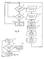
- FIG. 5 is a flow chart diagram setting forth an alternative method for computing transmit power levels.
- FIGS. 6A and 6B are flow chart diagrams illustrating methods that facilitate the computation of transmit power levels for a plurality of access elements, taking location information into account.
- FIG. 7 is a functional block diagram illustrating the functional elements associated with the coverage hole detection mechanism according to an embodiment of the present invention and the packet flow across these functional elements.
- FIGS. 8A , 8 B and 8 C are flow charts illustrating methods, according to embodiments of the present invention, directed to the collection and analysis of coverage data.
- FIG. 1 illustrates a computer network environment including dynamic transmit power configuration functionality according to an embodiment of the present invention.
- the computer network environment depicted in FIG. 1 includes access elements 12 , 13 , 14 , 15 deployed across wide area network 50 comprising a plurality of local area network segments 10 .
- the present invention further includes coverage analyzer 21 to receive coverage data from access elements 12 , 13 , 14 , 15 and process the coverage data to compute transmit power levels for the access elements to optimize the performance of the wireless network environment, as described below.
- the access elements are operative to establish wireless connections with remote client elements, such as remote client elements 16 , 18 , 20 and 22 .
- the access elements can operate to bridge wireless traffic between the remote client elements and a wired computer network such as wide area network (WAN) 50 , and/or act as hubs to route data between remote client elements within their respective coverage areas.
- WAN wide area network
- the access elements in one embodiment, are operative to dynamically recognize new users/remote client elements and wirelessly communicate with one to a plurality of remote client elements.
- the access elements in one embodiment, each include a radio frequency transmitter/receiver unit or an infrared transmitter receiver unit, or both. However, any suitable means of wireless communication can be used.
- the access elements can operate in connection with any suitable wireless communications protocol, including 802.11a and 802.11b.
- the access elements feature a coverage scanning mode, according to which the access elements monitor their respective coverage areas for wireless traffic associated with neighboring access elements and clients and record data associated with the signal associated with the wireless traffic, such as signal strength.
- the coverage data can be transmitted to a central management device, such as the coverage analyzer 21 ( FIG. 1 ) or central control element 24 (see description below and FIGS. 2A and 2B ) for processing.
- the access elements operate in a normal access point mode bridging wireless traffic between WAN 50 and the remote client elements and/or acting as a hub between remote wireless clients.
- the access elements switch to a coverage scanning mode according to which they each monitor for wireless traffic for a coverage scanning period.
- the coverage scanning interval and/or the scanning period can be configurable parameters allowing network administrators to specify the scanning behavior of each access element individually or as a group. For example, a typical coverage scanning period may span 50-60 milliseconds, while a typical interval between scans (scanning interval) may be ten to fifteen seconds.
- the access elements can either just disappear (from the perspective of the remote client elements) for the scan period, or use the mechanism in 802.11 for “contention-free periods” to halt the transmissions of the mobile stations before going off channel to perform the scan.
- the access elements each include a scanning daemon that, when invoked at each scanning interval, switches operation of the access element to coverage scan mode.
- the scanning daemon monitors for wireless traffic on a given frequency channel and records scan data characterizing any packets detected on the channel.
- the scanning daemon in one embodiment, monitors wireless traffic on a given channel and then switches to another frequency channel.
- the scanning daemon can operate in a variety of manners during the scanning period. For example, the scanning daemon can monitor for wireless traffic on a single frequency channel for the entire scanning period and switch to another frequency channel in a subsequent scanning period. Alternatively, the scanning daemon can scan a plurality of frequency channels during a given scan period.
- the scanning daemon can be configured to transmit the coverage scan data directly to a central repository, such as coverage analyzer 21 , or store it locally for later transmission in response to a request from the coverage analyzer 21 .
- 802.11 wireless network environments feature a number of different frame or packet types and sub-types, such as management frames (e.g., association requests and responses), control frames (e.g., request-to-send frames, and acknowledgments), and data frames. Every 802.11 frame includes a frame control field that allows for resolution of frame type, as well as whether the frame is sourced from a client or an access element. In addition, 802.11 frames also include the MAC addresses of the source and destination stations.
- management frames e.g., association requests and responses
- control frames e.g., request-to-send frames, and acknowledgments
- data frames e.g., data frames.
- Every 802.11 frame includes a frame control field that allows for resolution of frame type, as well as whether the frame is sourced from a client or an access element.
- 802.11 frames also include the MAC addresses of the source and destination stations.
- Certain 802.11 frames also include the Service Set Identifier (SSID) associated with the access point or element, such as beacon frames, probe responses and association requests.
- the scanning daemon is configured to record data only for frames transmitted by other access elements.
- the scanning daemon can be configured to record data for detected beacon frames, probe responses, authentication responses, and data frames transmitted by access elements.
- the scanning daemon can parse the information in the detected packets and construct a table or other data structure including one or more scan data fields.
- the coverage scan data fields can include MAC address, SSID, frequency channel and any other information available from 802.11 frame headers, as well as an indicator of the strength of the detected signal associated with the packet (see below).
- the scanning daemon can record information on all packets detected during a scan, or summarize the information to eliminate redundant information.
- the access elements include functionality allowing for detection of the strength of the received signals.
- the IEEE 802.11 standard defines a mechanism by which RF energy is to be measured by the circuitry (e.g., chip set) on a wireless network adapter or interface card.
- the 802.11 protocol specifies an optional parameter, the receive signal strength indicator (RSSI). This parameter is a measure by the PHY sub-layer of the energy observed at the antenna used to receive the current packet. RSSI is measured between the beginning of the start frame delimiter (SFD) and the end of the PLCP header error check (HEC). This numeric value is an integer with an allowable range of 0-255 (a 1-byte value).
- each vendor's 802.11-compliant adapter has a specific maximum RSSI value (“RSSI_Max”). Therefore, the RF energy level reported by a particular vendor's wireless network adapter will range between 0 and RSSI_Max. Resolving a given RSSI value reported by a given vendor's chip set to an actual power value (dBm) can be accomplished by reference to a conversion table. In addition, some wireless networking chip sets actually report received signal strength in dBm units, rather than or in addition to RSSI.
- the access elements 12 , 14 include the detected signal strength value associated with a packet in the coverage scan table. In one embodiment, the scan data fields can also include a time stamp indicating when the packet was detected.
- Coverage analyzer 21 is a network device that receives coverage scan data from the access elements and processes the coverage scan data, in one embodiment, to compute an optimal set of transmit power levels for the access elements.
- the functionality of coverage analyzer 21 can be incorporated into a wireless network management platform or appliance. As discussed below, the functionality of coverage analyzer may also be incorporated into one or more central control elements 24 , 26 as discussed more fully below.
- coverage analyzer 21 includes an access point table storing information relating to known access elements.
- the access point table includes an access element identifier field, and a current transmit power field.
- the access element identifier is the MAC address corresponding to a given access element, while the service set identifier is the SSID contained in certain management frames, such as beacon frames, probe response frames, and association request frames.
- the access point table can be manually configured by a network administrator with knowledge of the MAC address and the SSID of the access elements. In another embodiment, the access point table can be automatically populated using layer 2 and/or layer 3 discover mechanisms.
- the access elements can be configured to automatically transmit the coverage scan data to coverage analyzer 21 after each coverage scan. In another embodiment, the access elements can store the coverage scan data and transmit them in response to a request from coverage analyzer 21 .
- coverage analyzer 21 can be configured to execute the coverage analysis functionality at regular, configurable intervals, or on demand. In one embodiment, coverage analyzer 21 maintains, for each access element, a separate table or other data structure for the received coverage scan data. In one embodiment, coverage analyzer 21 can summarize the coverage scan data, for example, by averaging the detected signal strength values associated with packets transmitted from a given access element.
- FIG. 2A illustrates a computer network environment including an alternative wireless network system architecture.
- the coverage detection and configuration functionality according to the present invention can be implemented within the context of a hierarchical wireless network infrastructure.
- U.S. patent application Ser. No. 10/155,938 discloses a wireless network system having a hierarchical architecture for the management of multiple access elements by a central control element.
- FIG. 10/155,938 discloses a wireless network system having a hierarchical architecture for the management of multiple access elements by a central control element.
- FIG. 2A illustrates a hierarchical wireless networking system according to an embodiment of the present invention, including the following components: access elements 12 - 15 for wireless communication with remote client elements 16 , 18 , 20 , 22 , central control elements 24 , 26 , and means for communication between the access elements and the central control elements, typically direct line access 28 , 30 , but potentially a wireless backbone, fiber or other reliable link.
- access elements 12 , 14 are directly connected to LAN 10 or a virtual local area network (VLAN) for communication with central control element 24 .
- VLAN virtual local area network
- the access elements 12 - 15 are coupled via communication means using a wireless local area network (WLAN) protocol (e.g., IEEE 802.11a, 802.11b, etc.) to the client remote elements 16 , 18 , 20 , 22 .
- WLAN wireless local area network
- the communications means 28 , 30 between the access elements 12 , 14 and the central control element 24 is typically an Ethernet network, but it could be anything else which is appropriate to the environment.
- the access elements 12 , 14 and the central control element 24 tunnel network traffic associated with corresponding remote client elements 16 , 18 ; 20 , 22 via direct access lines 28 and 30 , respectively.
- the access elements 12 , 14 and central control element 24 may tunnel wireless traffic over a LAN or virtual LAN.
- Central control element 24 is also operative to bridge the network traffic between the remote client elements 16 , 18 ; 20 , 22 transmitted through the tunnel with corresponding access elements 12 , 14 .
- central control element 24 operates to perform link layer management functions, such as authentication and association on behalf of access elements 12 , 14 .
- the central control element 24 provides processing to dynamically configure a wireless Local Area Network of a system according to the invention while the access elements 12 , 14 provide the acknowledgement of communications with the client remote elements 16 , 18 , 20 , 22 .
- the central control element 24 may for example process the wireless LAN network management messages, load control, channel control, and handoff.
- the network management messages are authentication requests of the client wireless access elements 12 , 14 and association requests of the client wireless access elements 12 , 14 .
- the network management messages are passed on from the client remote elements 16 , 18 ; 20 , 22 via the access elements 12 , 14 , such as authentication requests and authorization requests, whereas the access elements 12 , 14 provide immediate acknowledgment of the communication of those messages without conventional processing thereof.
- the central control element 24 may for example process physical layer information.
- the central control element 24 may for example process information collected at the access elements 12 , 14 on channel characteristic, propagation, and interference or noise.
- Central control element 26 and associated access elements 13 , 15 operate in a similar or identical manner.
- the central control elements 24 , 26 may each incorporate the functionality of coverage analyzer 21 (see above) to receive coverage scan data from the access elements to which they are associated and process the coverage scan data to compute an transmit power levels for the access elements.
- central control element 24 may be connected to a set of access elements installed on one floor of an enterprise facility, while central control element 26 may be operably connected to a set of access elements installed on a different floor of the facility.
- Access elements 12 - 15 are configured, as discussed above, to switch to a scan mode for a scanning period at regular scanning intervals, and transmit coverage scan data to the corresponding central control elements.
- the central control elements 24 , 26 are configured to automatically discover the access elements to which they are connected by various layer 2 and 3 discovery mechanisms, and populate the access point table.
- Central control elements 24 , 26 in one embodiment, act independently with respect to each other; that is, for deployments where there is no overlap in coverage areas among the access elements 12 - 15 , central control elements 24 , 26 need not share access element information. However, in other deployments where there is coverage overlap, sharing of coverage scan and configuration information may be desirable.
- one of central control elements 24 , 26 can be configured to perform the coverage analysis and configuration functionality described herein on behalf of the entire system.
- central control elements 24 , 26 can be configured to automatically discover each other over LAN 10 or WAN 50 using layer 2 and/or layer 3 discovery mechanisms as well.
- the central control elements 24 , 26 can also be manually configured with knowledge of each other. Since access elements 13 , 15 may be detected during a scan by either access elements 12 or 14 , the central control elements exchange access point table information. In the example of FIG. 2A , central control element 24 would provide to central control element 26 the MAC addresses and SSIDs associated with access elements 12 , 14 .
- central control element 26 would provide to central control element 24 the MAC addresses and SSIDs associated with access element 13 , 15 .
- Each central control element 24 , 26 adds the information to the access point tables to allow for proper identification of the access elements. Such exchanges of information can be performed at periodic intervals or in response to updates to the access point table.
- central control element 24 (as well as other central control elements not shown) can communicate with access elements 12 , 14 over local area network segment 10 .
- central control element 24 may also communicate with access element 15 over WAN 50 .
- Suitable VLAN protocols include the IEEE 802.1Q (VLAN tagging) protocol or any other protocol allowing for a logic or virtual link layer connection between the central control element and the access elements.
- wireless traffic associated with remote client elements 16 , 18 ; 20 , 22 can be tunneled between the central control element 24 and the access elements 12 , 14 .
- access elements 12 , 14 can operate to directly bridge network traffic between remote client elements 16 , 18 ; 20 , 22 and WAN 50 , while tunneling network management messages, such as authentication and association requests from remote client elements to central control element 24 as discussed above.
- the access elements can be configured to broadcast management packets at periodic intervals on all available frequency channels for detection by neighboring access elements.
- each access element can be configured with knowledge of neighboring access elements and address such packets directly to them. This configuration ensures that coverage data exists for access elements that would otherwise be inactive.
- the access elements, detecting the broadcasted packets can be configured to store the MAC address of the broadcasting access element, the signal strength associated with the packet, and optionally a time stamp.
- the access elements need not go “off channel” to monitor for wireless traffic associated with its neighboring access elements, and can instead receive the packets in a normal access point mode configuration.
- the packets can be sent to a broadcast address or multicast address, where no knowledge of the other access elements is necessary.
- the dynamic transmit power functionality can operate in a variety of manners to achieve different objectives. As discussed below, the dynamic transmit power functionality can operate with or without location information for the access elements. In addition, the dynamic transmit power functionality can operate to minimize the coverage overlap of access points on the same channel, or minimize the converge overlap of access points regardless of channel. Still further, the dynamic transmit power functionality, according to one embodiment of the present invention, operates in conjunction with coverage hole detection functionality, described below, to prevent the transmit power of an access element from being reduced where client data indicates that the signal strength of the access element is below a desired performance level.
- the access elements include functionality allowing for detection of the strength of the signal received from client remote elements and neighboring access elements. Other attributes of the signal can be used in combination with received signal strength or as an alternative. For example, the detected Signal-to-Noise Ratio (SNR) during packet transmission can be used in determining the existence of coverage holes in the wireless network environment. Again, many chip sets include functionality and corresponding APIs to allow for a determination of SNRs associated with packets received from client remote elements.
- access elements 12 , 14 include the detected signal strength and/or SNR value associated with a packet in the physical layer information (PHY) field of the encapsulated 802.11 packet, as described in U.S. patent application Ser. No. 10/155,938.
- PHY physical layer information
- FIG. 7 is a functional block diagram illustrating the functional elements associated with the coverage hole detection mechanism according to an embodiment of the present invention.
- central control element 24 includes coverage analysis module 80 , stats collector 84 , database 86 and packet controller 82 .
- Packet flow controller 82 routes the data frames to and from the remote wireless clients through the access elements, and handles other tasks associated with operation of the wireless network environment, such as authentication and association (see above).
- stats collector 84 maintains one or more statistics characterizing various aspects of the wireless network environment based on an examination of the information contained in the packets traversing central control element 24 .
- Coverage analysis module 80 in one embodiment, is operative to periodically store the statistic(s) maintained by stats collector 84 in database 86 in association with a time stamp. Coverage analysis module 80 is further operative to analyze the data over a configurable time interval to detect a coverage hole associated with a given access element.
- FIG. 7 also shows the packet flow path according to an embodiment of the present invention.
- stats collector 84 maintains a histogram of signal strength on a per-access-element basis based on the signal strength information (e.g., SNR, RSSI, dBm) contained in the packet headers traversing central control element 24 .
- the received signal strength (dBm) of a packet received by an access element is recorded in a corresponding histogram having a range of ⁇ 100 dBm to ⁇ 10 dBm in increments of 1 dB bins.
- the exact range and number of bins may depend on the physical properties of the wireless network protocol and are also matters of engineering choice.
- stats collector 84 maintains other statistics associated with the signal strength histogram for each access element, such as number of samples, number of unique MAC addresses, etc.
- coverage analysis module 80 is operative to store the statistics in association with a time stamp in database 86 and reset the statistic values maintained by stats collector 84 .
- the received signal strength values maintained by stats collector 84 reflect the strength of the signal transmitted from the remote client element to the access element.
- the histogram can be shifted by the equation below to obtain an estimate of the signal strength of the access elements 12 , 14 relative to the remote client elements:
- ClientHistogram(x) RadioHistogram(x)+RadioEIRP ⁇ ClientEIRP), where RadioHistgram(x) is a histogram of signal strength maintained by stats collector 84 for a given access element, RadioEIRP is the transmit power (dBm) of the access element, ClientEIRP is the average transmit power (dBm) of the remote client elements, as detected by the packets traversing central control element 24 .
- the client transmit power, ClientEIRP is obtained by scanning the MAC addresses of the remote client elements against a table or other database that contains the transmit powers associated with different wireless adapters by vendor as identified by the first N bits of the MAC address.
- stats collector 84 is operative to perform the conversion as part of the statistics collection process. For example, stats collector 84 may be operative to poll the device/transmit power table using the MAC address of the remote client element to determine the ClientEIRP value and then estimate the signal strength of the access element based on the RadioEIRP, ClientEIRP and the received signal strength indicator.
- coverage analysis module 80 applies a filter to the histogram, RadioHistogram, before estimating the Client Histogram.
- RadioHistogram a filter to the histogram
- other embodiments of the present invention can use the RadioHistogram values, rather than estimating the Client Histogram.
- coverage analysis module 80 determines whether the level of coverage reflected by the histogram meets a minimum coverage profile configured by a network administrator.
- the minimum coverage profile specifies what percentage of the histogram samples should be above a specified threshold level (e.g., received signal strength, SNR, etc.). For example, a network administrator may specify that 95% of the estimated client samples should be above ⁇ 70 dBm.
- results of the analysis described above are stored and used in computing transmit powers for the access elements as described below, can be used in a variety of ways.
- coverage analysis as to each access element is based on a configurable percentage of mobile stations below a configurable threshold signal strength level, as opposed to the sample-based methodology discussed above.
- Stats collector 84 maintains, for each access element, a list of identifiers (e.g., MAC addresses) of the remote client elements that have established wireless connections.
- Stats collector 84 as to each mobile station identifier in the list, maintains the detect signal strength values associated with each packet corresponding to the remote client elements.
- FIG. 8A illustrates a method directed to the collection of signal strength data on a packet-by-packet basis for each mobile station. As FIG.
- stats collector 84 when it receives a data packet ( 402 ), determines whether the packet is associated with a new mobile station ( 404 ) and, if so, creates a new mobile station entry including the MAC address or other identifier corresponding to the mobile station ( 406 ).
- Stats collector 84 then records the signal strength value contained in the encapsulating packet header in associated with the corresponding mobile station identifier ( 408 ).
- a separate process scans the list of mobile station identifiers and deletes the entries where no activity has been detected after a threshold period of time as to that access element.
- stats collector 84 maintains the signal strength values for each packet traversing it for an averaging interval or window, at which point the coverage analysis module 80 polls the stats collector 84 for the collected data and then filters the signal strengths over the averaging interval.
- coverage analysis module 80 at a configurable averaging interval or window (e.g., 1 minute, etc.) ( 412 ), computes the average signal strength from the values collected during examination of each packet by stats collector 84 ( 422 ).
- coverage analysis module 80 stores the computer values in a persistent data store in association with a time stamp. As FIG. 8B shows, coverage analysis module 80 performs this computation for each access element ( 418 ) and each mobile station ( 420 ). In one embodiment, coverage analysis module 80 resets the counts maintained by stats collector 84 as it traverses the mobile stations ( 424 ).
- FIG. 8B also shows, stats collector 84 , at a configurable analysis interval (e.g., 3 minutes) ( 414 ), then analyzes the filtered coverage data ( 416 ).
- FIG. 8C illustrates a method, according to an embodiment of the present invention, directed to the analysis of coverage data.
- Coverage analysis module 80 as to each access element ( 430 ), first determines whether a minimum number of mobile stations have established wireless connections with the access element ( 432 ). If so, coverage analysis module 80 computes the average signal strength over the analysis interval for each mobile station ( 434 ). If a configurable threshold percentage of mobile stations associated with an average signal strength is less than a threshold level ( 436 ), coverage analysis module 80 , in one embodiment, sets a flag in a data structure associated with the access element ( 438 ).
- a configurable threshold percentage of mobile stations associated with an average signal strength is less than a threshold level ( 436 ).
- the signal strength histograms can be maintained at access elements 12 , 14 and retrieved on a periodic basis by central control element 24 via Simple Network Management Protocols (SNMP) or other query methods.
- SNMP Simple Network Management Protocol
- the connections between central control element 24 and the access elements 12 , 14 need not be through direct access lines 28 , 30 respectively.
- a variety of system architectures are possible.
- central control element 24 and the access elements can communicate over a Local Area Network, or over a VLAN in a Wide Area Network (WAN).
- WAN Wide Area Network
- central control element 24 and the access elements associated therewith can be deployed across a Wide Area Network, such as the Internet.
- central control element 24 bridges the wireless traffic between the remote client elements and network 50 .
- the access elements 12 , 14 bridge the wireless traffic between the remote client elements and network 50 .
- the present invention can also be applied to WLAN architectures beyond the hierarchical WLAN architecture described above.
- the coverage analysis functionality described herein can be implemented within the context of a single, autonomous access point, which can be configured to communicate with a central management platform via SNMP or other protocols.
- FIG. 3 illustrates a typical layout of access elements in the 2.4 GHz band using three non-overlapping channels, where the channels assigned to each access element have been optimized in some manner.
- the access elements are spaced relative to each other in the x, y and z axis dimensions, such as deployments in separate floors or levels 98 , 99 of an office building.
- the dynamic transmit power functionality is configured to minimize the coverage overlap of access elements on the same channel. It checks for neighboring access elements on the same channel whose signals are detected above a given threshold. In one embodiment, this algorithm works in conjunction with coverage hole detection functionality to ensure that a reduction in power will not adversely affect the performance of a given access element (see below).
- the dynamic transmit power functionality detects the coverage overlap between access elements that have the same channel assignment and reduces the power of each overlapping access element by an equal amount to achieve a desired intersection at a given coverage threshold level (e.g., ⁇ 85 dBm) between the access elements. In one embodiment, however, before lowering the transmit power, a coverage analyzer ensures that there are no coverage holes associated with the access elements on which power is to be reduced.
- a coverage threshold level e.g., ⁇ 85 dBm
- the dynamic transmit power functionality has access to a database including the signal strength values corresponding to neighboring access elements as detected by each access element.
- the database maintains a list or table for each access element of the detected access element(s) and a signal strength value associated with each detected access element.
- coverage analyzer 21 sorts each list or table by largest coverage overlap (i.e., signal strength value).
- coverage analyzer 21 assembles a two-dimensional matrix including the detected signal strengths among the access elements.
- the signal strength values in the coverage matrix can be the average signal strength values corresponding to the packets transmitted by the access elements.
- FIG. 4 illustrates a method directed to minimizing the coverage overlaps of access elements operating on the same channel.
- a group may be all access elements associated with a given central control element 24 , or all access elements in a given physical location, such as a floor of a building.
- coverage analyzer 21 for each access element (AP i ) ( 102 ), compares the signal strength detected by the access element from all other access elements (AP j ) in the matrix ( 104 ) against a coverage threshold. For example, in one embodiment, coverage analyzer 21 determines whether the signal strength, S ij , detected by AP i is greater than a coverage threshold of ⁇ 85 dBm ( 106 ). As FIG. 4 illustrates, coverage analyzer 21 also determines whether AP i and AP j operate on the same channel ( 108 ) and whether a coverage hole has been detected as to AP i ( 110 ).
- coverage analyzer 21 then reduces the transmit power, or generates an instruction to reduce the transmit power, for AP i and AP j ( 114 , 118 ), if the transmit power for AP i and/or AP j have not already been reduced during this analysis loop ( 112 , 116 ).
- coverage analyzer 21 reduces the transmit power of AP i and AP j each by 10 dB.
- the coverage threshold as well as the amount by which the transmit powers are reduced, can be fully parameterized and configurable by a network administrator. Coverage analyzer 21 repeats this process for all access elements until the entire matrix has been traversed.
- FIG. 3 illustrates that the goal of the method described above to ensure that the coverage areas of access elements do not overlap neighboring access elements assigned the same channel.
- the benefit of adjusting the transmit power only on access elements on the same channel is that the intervening access elements provide coverage between the overlapping access elements and buffer to account for the difference between the pathloss exponent between access elements and the pathloss exponent between access elements and remote client elements.
- the intervening access elements provide coverage between the overlapping access elements and buffer to account for the difference between the pathloss exponent between access elements and the pathloss exponent between access elements and remote client elements.
- other transmit power configuration schemes are possible.
- FIG. 5 illustrates a method directed to minimize the coverage overlap at a given threshold level between all access elements without regard to assigned channels. Rather, as FIG. 5 illustrates, coverage analyzer 21 can be configured to lower the transmit power of an access element where it overlaps above a threshold number coverage areas associated with other access elements. As with the method illustrated in FIG. 4 , coverage analyzer 21 traverses an i ⁇ j matrix of signal strengths detected by the access elements. Accordingly, coverage analyzer 21 , for each access element (AP i ) ( 202 ), first determines whether a coverage hole has been detected as to that access element ( 204 ).
- coverage analyzer 21 For each access element AP j ( 206 ), coverage analyzer 21 compares the strength of the signal S ji , transmitted by AP i as detected by AP j ( 208 ), and increments a counter, OverlapCount, if Sji exceeds a coverage threshold (e.g., ⁇ 85 dBm) ( 210 ). If the OverlapCount exceeds a threshold value ( 212 ), coverage analyzer 21 reduces the transmit power of AP i ( 214 ). Coverage analyzer 21 repeats this process until all access elements in the matrix have been traversed.
- a coverage threshold e.g., ⁇ 85 dBm
- the dynamic transmit power functionality may also take location information into account.
- the access point table includes positional coordinates of each access element and further includes a z-axis dimension such as floor height or level, which can be configured by a network administrator or determined automatically through known components, such as a Global Positioning System (GPS) receiver.
- GPS Global Positioning System
- coverage analyzer 21 first calculates the coverage overlaps relative to all quadrants for each access element, and then adjusts the transmit power for any access element where there is overlap in all for quadrants.
- coverage analyzer 21 computes the pathloss exponent, ExpPLij, between access element AP i and all neighboring access elements AP j ( 308 , 310 ).
- a pathloss exponent between access element AP i and a remote client element can be estimated ( 312 ).
- the estimated client pathloss exponent is derived by multiplying the pathloss exponent between access elements, ExpPL ij , by a factor, as illustrated in Equation (2).
- coverage analyzer 21 calculates the coverage overlaps in all quadrants relative to each access element, and adjusts the transmit power where there is overlap in all quadrants.
- coverage analyzer computes, for each access element (AP i ) ( 320 ), the coverage threshold overlap between all neighboring access elements (AP j ) in each quadrant relative to each quadrant ( 322 , 324 , 326 ). Equation (3) illustrates how coverage overlap can be computed according to one embodiment of the present invention.
- O ijq d ij ⁇ ( R iq +R jq ) (3)
- the overlap in a given quadrant q between two access elements i and j is the difference between the distance, d ij , between the access elements and the sum of their coverage radii, R, at the threshold power level.
- a negative value indicates no coverage overlap.
- coverage analyzer 21 determines the lowest computed coverage overlap from the values computed for a given access element ( 328 ) and adjusts the transmit power of the access element, AP i , if the minimum computed coverage overlap is a positive value (indicating coverage overlap) ( 330 ). In one embodiment, coverage analyzer 21 adjusts the transmit power of the access element, AP i , if the minimum coverage overlap is greater than a threshold value. Coverage analyzer 21 repeats this process for all desired access elements.
Abstract
Description
-
- BSNRadioHistFil(x)=. . .
- The RSSI histogram struct:
- typedef struct {
- int NumberOfSamples;
- int NumberOfUniqueMACIDs;
- time TimeOfFirstSample;
- time TimeOfLastSample;
- int RadioHistogram[100];
- int ClientHistogram[100];
- }
ClientHistogram(x)=RadioHistogram(x)+RadioEIRP−ClientEIRP),
where RadioHistgram(x) is a histogram of signal strength maintained by
From the pathloss exponent between access elements APi and APj, a pathloss exponent between access element APi and a remote client element can be estimated (312). In one embodiment, the estimated client pathloss exponent is derived by multiplying the pathloss exponent between access elements, ExpPLij, by a factor, as illustrated in Equation (2).
ExpClientij=ExpPLij*Factor (2)
The multiplication factor above can be a configurable parameter and/or experimentally determined by comparing signal strengths detected between access elements with concurrent monitoring of the signal strength of access elements with wireless network testing equipment. With the estimated client pathloss exponent, ExpClientij,
O ijq =d ij−(R iq +R jq) (3)
The overlap in a given quadrant q between two access elements i and j is the difference between the distance, dij, between the access elements and the sum of their coverage radii, R, at the threshold power level. A negative value indicates no coverage overlap.
Claims (14)
Priority Applications (2)
| Application Number | Priority Date | Filing Date | Title |
|---|---|---|---|
| US10/407,372 US7313113B1 (en) | 2003-04-04 | 2003-04-04 | Dynamic transmit power configuration system for wireless network environments |
| US11/937,235 US7489661B2 (en) | 2003-04-04 | 2007-11-08 | Dynamic transmit power configuration system for wireless network environments |
Applications Claiming Priority (1)
| Application Number | Priority Date | Filing Date | Title |
|---|---|---|---|
| US10/407,372 US7313113B1 (en) | 2003-04-04 | 2003-04-04 | Dynamic transmit power configuration system for wireless network environments |
Related Child Applications (1)
| Application Number | Title | Priority Date | Filing Date |
|---|---|---|---|
| US11/937,235 Continuation US7489661B2 (en) | 2003-04-04 | 2007-11-08 | Dynamic transmit power configuration system for wireless network environments |
Publications (1)
| Publication Number | Publication Date |
|---|---|
| US7313113B1 true US7313113B1 (en) | 2007-12-25 |
Family
ID=38863322
Family Applications (2)
| Application Number | Title | Priority Date | Filing Date |
|---|---|---|---|
| US10/407,372 Active 2026-01-25 US7313113B1 (en) | 2003-04-04 | 2003-04-04 | Dynamic transmit power configuration system for wireless network environments |
| US11/937,235 Active US7489661B2 (en) | 2003-04-04 | 2007-11-08 | Dynamic transmit power configuration system for wireless network environments |
Family Applications After (1)
| Application Number | Title | Priority Date | Filing Date |
|---|---|---|---|
| US11/937,235 Active US7489661B2 (en) | 2003-04-04 | 2007-11-08 | Dynamic transmit power configuration system for wireless network environments |
Country Status (1)
| Country | Link |
|---|---|
| US (2) | US7313113B1 (en) |
Cited By (42)
| Publication number | Priority date | Publication date | Assignee | Title |
|---|---|---|---|---|
| US20050213579A1 (en) * | 2004-03-23 | 2005-09-29 | Iyer Pradeep J | System and method for centralized station management |
| US20060105759A1 (en) * | 2004-10-20 | 2006-05-18 | Alcatel | Management server for determining perceived quality of service maps in a mobile communication network |
| US20060198312A1 (en) * | 2005-02-01 | 2006-09-07 | Schondelmayer Adam H | Network diagnostic systems and methods for altering the format and bandwidth of network messages |
| US20060200711A1 (en) * | 2005-02-01 | 2006-09-07 | Schondelmayer Adam H | Network diagnostic systems and methods for processing network messages |
| US20060198319A1 (en) * | 2005-02-01 | 2006-09-07 | Schondelmayer Adam H | Network diagnostic systems and methods for aggregated links |
| US20060223545A1 (en) * | 2005-03-31 | 2006-10-05 | Borst Simon C | Power load balancing in cellular networks |
| US20060264178A1 (en) * | 2005-05-20 | 2006-11-23 | Noble Gayle L | Wireless diagnostic systems |
| US20070026887A1 (en) * | 2005-07-27 | 2007-02-01 | Mitsubishi Denki Kabushiki Kaisha | Method for transferring information related to at least a mobile terminal in a mobile telecommunication network |
| US20070038880A1 (en) * | 2005-08-15 | 2007-02-15 | Noble Gayle L | Network diagnostic systems and methods for accessing storage devices |
| US20070061442A1 (en) * | 2004-01-14 | 2007-03-15 | Kan Siew L | System and method for planning a wireless computer network using network performance contour overlays |
| US20070211696A1 (en) * | 2006-03-13 | 2007-09-13 | Finisar Corporation | Method of generating network traffic |
| US20070223403A1 (en) * | 2004-07-01 | 2007-09-27 | Anders Furuskar | Power Control In a Communication Network and Method |
| US20070253395A1 (en) * | 2004-02-05 | 2007-11-01 | James Graves | Wireless network detector |
| US20080075103A1 (en) * | 2005-05-20 | 2008-03-27 | Finisar Corporation | Diagnostic device |
| US20080173561A1 (en) * | 2007-01-19 | 2008-07-24 | Jackson W Shaun | Portable electronic devices and carrying cases with built-in network detectors |
| US20080186917A1 (en) * | 2007-02-02 | 2008-08-07 | Microsoft Corporation | Decoupling scanning from handoff for reduced delay over wireless LAN |
| US7489661B2 (en) * | 2003-04-04 | 2009-02-10 | Cisco Systems, Inc. | Dynamic transmit power configuration system for wireless network environments |
| US20090052350A1 (en) * | 2007-08-09 | 2009-02-26 | Nortel Networks Limited | Auto-discovery and management of base station neighbors in wireless networks |
| US7539169B1 (en) | 2003-06-30 | 2009-05-26 | Cisco Systems, Inc. | Directed association mechanism in wireless network environments |
| US7596376B2 (en) | 2005-02-18 | 2009-09-29 | Cisco Technology, Inc. | Methods, apparatuses and systems facilitating client handoffs in wireless network systems |
| KR100933135B1 (en) | 2008-02-28 | 2009-12-21 | 주식회사 케이티 | Method and system for compensating failure of indoor base station |
| US20100091746A1 (en) * | 2008-10-14 | 2010-04-15 | Aihua Edward Li | COVERAGE-HOLE DETECTION and SELF HEALING |
| US7805140B2 (en) | 2005-02-18 | 2010-09-28 | Cisco Technology, Inc. | Pre-emptive roaming mechanism allowing for enhanced QoS in wireless network environments |
| WO2010115467A1 (en) * | 2009-04-09 | 2010-10-14 | Telefonaktiebolaget Lm Ericsson (Publ) | Splitter with adaptive power distribution |
| WO2010115468A1 (en) * | 2009-04-09 | 2010-10-14 | Telefonaktiebolaget Lm Ericsson (Publ) | Filter for an indoor cellular system |
| US7821986B2 (en) | 2006-05-31 | 2010-10-26 | Cisco Technology, Inc. | WLAN infrastructure provided directions and roaming |
| US7899057B2 (en) | 2006-04-28 | 2011-03-01 | Jds Uniphase Corporation | Systems for ordering network packets |
| KR101023566B1 (en) * | 2009-05-12 | 2011-03-21 | 주식회사 케이티 | Method and apparatus for managing base transceiver station |
| US20110222434A1 (en) * | 2010-03-10 | 2011-09-15 | Fujitsu Limited | Method and Apparatus for Deploying a Wireless Network |
| US20110223960A1 (en) * | 2010-03-10 | 2011-09-15 | Fujitsu Limited | System and Method for Implementing Power Distribution |
| US8107822B2 (en) | 2005-05-20 | 2012-01-31 | Finisar Corporation | Protocols for out-of-band communication |
| US20120087267A1 (en) * | 2010-10-06 | 2012-04-12 | John Peter Norair | Method and Apparatus for Adaptive Searching of Distributed Datasets |
| US8213333B2 (en) | 2006-07-12 | 2012-07-03 | Chip Greel | Identifying and resolving problems in wireless device configurations |
| US20130107697A1 (en) * | 2011-11-01 | 2013-05-02 | Av Tech Corporation | Network Connection System of Network Electronic Device and Method to Solve Terminal Device Unable to Reach Electronic Device Caused by Router Not Supporting NAT Loopback |
| US8457038B1 (en) * | 2010-10-27 | 2013-06-04 | Sprint Communications Company L.P. | Velocity based handoff determination in wireless communication system |
| US8526821B2 (en) | 2006-12-29 | 2013-09-03 | Finisar Corporation | Transceivers for testing networks and adapting to device changes |
| US20140024403A1 (en) * | 2012-07-23 | 2014-01-23 | Huawei Device Co., Ltd | Channel switching method, apparatus, and system |
| US9137716B1 (en) | 2013-12-27 | 2015-09-15 | Sprint Communications Company L.P. | Mobility based frequency band selection in wireless communication systems |
| US20150288534A1 (en) * | 2010-12-17 | 2015-10-08 | Texas Instruments Incorporated | Carrier sense multiple access (csma) protocols for power line communications (plc) |
| US20160219444A1 (en) * | 2015-01-27 | 2016-07-28 | Kathrein-Werke Kg | System and Method for Analysis Of Blocking Interferers |
| US9432848B2 (en) | 2004-03-23 | 2016-08-30 | Aruba Networks, Inc. | Band steering for multi-band wireless clients |
| EP3576448A4 (en) * | 2017-01-27 | 2020-11-11 | Nippon Telegraph And Telephone Corporation | Wireless communication system and wireless communication method |
Families Citing this family (12)
| Publication number | Priority date | Publication date | Assignee | Title |
|---|---|---|---|---|
| US7925266B1 (en) * | 2006-06-15 | 2011-04-12 | Nextel Communications Inc. | Method for selecting wireless transmission site locations |
| US8301913B2 (en) * | 2009-02-16 | 2012-10-30 | Broadcom Corporation | System and method for dynamic power provisioning for a wireless access point |
| US9003205B2 (en) * | 2009-03-31 | 2015-04-07 | Symbol Technologies, Inc. | Method to lower the operating cost of wireless network by enforcing low power infrastructure operation |
| US8699392B2 (en) | 2010-10-26 | 2014-04-15 | Motorola Solutions, Inc. | Method and apparatus for conserving access point power usage during low network usage intervals |
| GB2487222B (en) * | 2011-01-14 | 2015-02-25 | Fujitsu Ltd | Coverage hole compensation in a cellular wireless network |
| US9279878B2 (en) | 2012-03-27 | 2016-03-08 | Microsoft Technology Licensing, Llc | Locating a mobile device |
| US8862067B2 (en) * | 2012-03-27 | 2014-10-14 | Microsoft Corporation | Proximate beacon identification |
| US9612121B2 (en) | 2012-12-06 | 2017-04-04 | Microsoft Technology Licensing, Llc | Locating position within enclosure |
| US11228925B2 (en) | 2015-07-01 | 2022-01-18 | Comcast Cable Communications, Llc | Providing utilization information for intelligent selection of operating parameters of a wireless access point |
| US9961576B2 (en) | 2015-10-15 | 2018-05-01 | Comcast Cable Communications, Llc | Wi-Fi radio health score |
| US11405800B2 (en) * | 2018-07-17 | 2022-08-02 | Jio Platforms Limited | System and method for 3D propagation modelling for planning of a radio network |
| CN112449361B (en) * | 2019-09-02 | 2022-10-18 | 华为技术有限公司 | Detection method, device and system |
Citations (39)
| Publication number | Priority date | Publication date | Assignee | Title |
|---|---|---|---|---|
| US5491692A (en) | 1991-06-14 | 1996-02-13 | Digital Equipment International Limited | Hybrid units for a communication network |
| US5684860A (en) * | 1992-12-01 | 1997-11-04 | Milani; Carlo | Apparatus for automatically distributing calls between users and a fleet of mobile stations through a central station |
| US5940384A (en) * | 1995-03-13 | 1999-08-17 | Airnet Communications Corporation | Wideband wireless base station making use of time division multiple access bus having selectable number of time slots and frame synchronization to support different modulation standards |
| US6097956A (en) * | 1997-10-24 | 2000-08-01 | Nortel Networks Corporation | Accurate calculation of the probability of outage for the CDMA reverse link |
| US6104928A (en) * | 1997-10-07 | 2000-08-15 | Nortel Dasa Network System Gmbh & Co. Kg | Dual network integration scheme |
| US6140964A (en) | 1996-03-22 | 2000-10-31 | Matsushita Electric Industrial Co., Ltd. | Wireless communication system and method and system for detection of position of radio mobile station |
| US6167274A (en) | 1997-06-03 | 2000-12-26 | At&T Wireless Svcs. Inc. | Method for locating a mobile station |
| US6208629B1 (en) * | 1996-04-30 | 2001-03-27 | 3Com Corporation | Method and apparatus for assigning spectrum of a local area network |
| US6223028B1 (en) * | 1997-03-17 | 2001-04-24 | Nortel Networks Ltd | Enhanced method and system for programming a mobile telephone over the air within a mobile telephone communication network |
| US6240077B1 (en) * | 1998-07-09 | 2001-05-29 | Golden Gate Tele Systems Inc. | Dynamic wireless multiplexing — switching hub for providing two-way communications with subscriber units |
| US6243413B1 (en) * | 1998-04-03 | 2001-06-05 | International Business Machines Corporation | Modular home-networking communication system and method using disparate communication channels |
| US6286038B1 (en) | 1998-08-03 | 2001-09-04 | Nortel Networks Limited | Method and apparatus for remotely configuring a network device |
| US6338140B1 (en) | 1998-07-27 | 2002-01-08 | Iridium Llc | Method and system for validating subscriber identities in a communications network |
| US6473038B2 (en) | 2001-01-05 | 2002-10-29 | Motorola, Inc. | Method and apparatus for location estimation |
| US20020168958A1 (en) | 2001-05-14 | 2002-11-14 | International Business Machines Corporation | System and method for providing personal and emergency service hailing in wireless network |
| US20020188723A1 (en) | 2001-05-11 | 2002-12-12 | Koninklijke Philips Electronics N.V. | Dynamic frequency selection scheme for IEEE 802.11 WLANs |
| US20020194384A1 (en) | 2000-10-30 | 2002-12-19 | Joerg Habetha | Ad hov networks comprinsing a plurlity of terminals for determining terminals as controllers of sub-networks |
| US20030023746A1 (en) * | 2001-07-26 | 2003-01-30 | Koninklijke Philips Electronics N.V. | Method for reliable and efficient support of congestion control in nack-based protocols |
| US20030117985A1 (en) | 2001-12-26 | 2003-06-26 | International Business Machines Corporation | Network security system, computer, access point recognizing method, access point checking method, program, storage medium, and wireless lan device |
| US20030188006A1 (en) | 2002-03-28 | 2003-10-02 | Bard Steven R. | Wireless LAN with dynamic channel access management |
| US20030198208A1 (en) * | 2002-04-19 | 2003-10-23 | Koos William M. | Data network having a wireless local area network with a packet hopping wireless backbone |
| US20030224787A1 (en) | 2001-11-28 | 2003-12-04 | Gandolfo Pierre T. | System and method of communication between multiple point-coordinated wireless networks |
| US6664925B1 (en) | 2002-05-02 | 2003-12-16 | Microsoft Corporation | Method and system for determining the location of a mobile computer |
| US20040111607A1 (en) | 2002-12-06 | 2004-06-10 | International Business Machines Corporation | Method and system for configuring highly available online certificate status protocol responders |
| US6754488B1 (en) | 2002-03-01 | 2004-06-22 | Networks Associates Technologies, Inc. | System and method for detecting and locating access points in a wireless network |
| US6760318B1 (en) * | 2002-01-11 | 2004-07-06 | Airflow Networks | Receiver diversity in a communication system |
| US6760671B1 (en) * | 2002-04-09 | 2004-07-06 | Cisco Technology, Inc. | Method and apparatus of low power energy detection for a WLAN |
| US6788658B1 (en) * | 2002-01-11 | 2004-09-07 | Airflow Networks | Wireless communication system architecture having split MAC layer |
| US6799047B1 (en) | 1999-02-25 | 2004-09-28 | Microsoft Corporation | Locating and tracking a user in a wireless network through environmentally profiled data |
| US20040203910A1 (en) | 2002-12-31 | 2004-10-14 | International Business Machines Corporation | Spatial boundary admission control for wireless networks |
| US6810428B1 (en) | 1997-06-06 | 2004-10-26 | Iwics Inc. | Method of operation of a multi-station network |
| US6917819B2 (en) | 2001-12-31 | 2005-07-12 | Samsung Electronics Co., Ltd. | System and method for providing a subscriber database using group services in a telecommunication system |
| US6925070B2 (en) | 2000-07-31 | 2005-08-02 | Ipr Licensing, Inc. | Time-slotted data packets with a preamble |
| US6990428B1 (en) | 2003-07-28 | 2006-01-24 | Cisco Technology, Inc. | Radiolocation using path loss data |
| US7068644B1 (en) | 2000-02-28 | 2006-06-27 | Sprint Spectrum L.P. | Wireless access gateway to packet switched network |
| US7085576B2 (en) * | 2002-12-30 | 2006-08-01 | Motorola, Inc. | Method and apparatus for providing streaming information to a wireless mobile wireless device |
| US7099669B2 (en) * | 1997-12-23 | 2006-08-29 | Cingular Wireless Ii, Llc | Method and system for optimizing performance of a mobile communications system |
| US7133909B2 (en) | 2001-01-12 | 2006-11-07 | Microsoft Corporation | Systems and methods for locating mobile computer users in a wireless network |
| US7161914B2 (en) * | 2002-04-11 | 2007-01-09 | Ntt Docomo, Inc. | Context aware application level triggering mechanism for pre-authentication, service adaptation, pre-caching and handover in a heterogeneous network environment |
Family Cites Families (67)
| Publication number | Priority date | Publication date | Assignee | Title |
|---|---|---|---|---|
| US4398063A (en) | 1980-10-24 | 1983-08-09 | Hass Ronald J | Mobile telephone interoffice handoff limiting method and apparatus |
| SE9302140L (en) | 1993-06-21 | 1994-08-29 | Televerket | Procedure for locating mobile stations in digital telecommunications networks |
| CA2129200C (en) * | 1994-07-29 | 1999-08-10 | Murray C. Baker | Access point switching for mobile wireless network node |
| KR100303633B1 (en) | 1996-03-05 | 2001-09-24 | 가부시키가이샤 로가스 | System for detecting positional information |
| US6249252B1 (en) | 1996-09-09 | 2001-06-19 | Tracbeam Llc | Wireless location using multiple location estimators |
| US6112095A (en) | 1997-01-08 | 2000-08-29 | Us Wireless Corporation | Signature matching for location determination in wireless communication systems |
| CN1249885A (en) | 1997-03-11 | 2000-04-05 | 洛克斯股份有限公司 | Field intensity distribution generator |
| WO1999008909A1 (en) | 1997-08-20 | 1999-02-25 | Locus Corporation | Positioning system and mobile communication device |
| US6115605A (en) | 1997-08-29 | 2000-09-05 | Ppm, Inc. | Communication system and device using dynamic receiver addressing |
| US6212391B1 (en) | 1997-12-01 | 2001-04-03 | Motorola, Inc. | Method for positioning gsm mobile station |
| US6414634B1 (en) | 1997-12-04 | 2002-07-02 | Lucent Technologies Inc. | Detecting the geographical location of wireless units |
| JPH11205845A (en) | 1998-01-14 | 1999-07-30 | Locus:Kk | Position specifying system |
| US6097596A (en) * | 1998-02-12 | 2000-08-01 | International Business Machines Corporation | Portable computer rotational heat pipe heat transfer |
| US6081229A (en) | 1998-03-17 | 2000-06-27 | Qualcomm Incorporated | System and method for determining the position of a wireless CDMA transceiver |
| US7025209B2 (en) | 1998-05-29 | 2006-04-11 | Palmsource, Inc. | Method and apparatus for wireless internet access |
| US6456892B1 (en) | 1998-07-01 | 2002-09-24 | Sony Electronics, Inc. | Data driven interaction for networked control of a DDI target device over a home entertainment network |
| US6441777B1 (en) | 1998-08-26 | 2002-08-27 | Mcdonald Keith D. | Signal structure and processing technique for providing highly precise position, velocity, time and attitude information with particular application to navigation satellite systems including GPS |
| US6269246B1 (en) | 1998-09-22 | 2001-07-31 | Ppm, Inc. | Location determination using RF fingerprinting |
| US6198935B1 (en) | 1998-11-17 | 2001-03-06 | Ericsson Inc. | System and method for time of arrival positioning measurements based upon network characteristics |
| KR100403748B1 (en) | 1999-01-23 | 2003-11-03 | 삼성전자주식회사 | Method for tracking a location of mobile telephone in mobile telecommunication network |
| US6473413B1 (en) | 1999-06-22 | 2002-10-29 | Institute For Information Industry | Method for inter-IP-domain roaming across wireless networks |
| US6282427B1 (en) | 1999-07-14 | 2001-08-28 | Telefonaktiebolaget L M Ericsson (Publ) | Selection of location measurement units for determining the position of a mobile communication station |
| US6766453B1 (en) * | 2000-04-28 | 2004-07-20 | 3Com Corporation | Authenticated diffie-hellman key agreement protocol where the communicating parties share a secret key with a third party |
| US6954641B2 (en) | 2000-08-14 | 2005-10-11 | Vesivius, Inc. | Communique wireless subscriber device for a cellular communication network |
| JP2002101460A (en) | 2000-09-25 | 2002-04-05 | Pioneer Electronic Corp | Mobile communication unit and method |
| US6556942B1 (en) | 2000-09-29 | 2003-04-29 | Ut-Battelle, Llc | Short range spread-spectrum radiolocation system and method |
| KR100407330B1 (en) | 2001-02-05 | 2003-11-28 | 삼성전자주식회사 | Method for roaming service of mobile telecommunication terminal |
| GB2371931B (en) | 2001-02-06 | 2004-10-20 | Nokia Mobile Phones Ltd | Processing received signals |
| US7035236B2 (en) | 2001-03-30 | 2006-04-25 | Telcordia Technologies, Inc. | Network-layer and link-layer use of shadow addresses with IP-based base stations |
| US20020174335A1 (en) | 2001-03-30 | 2002-11-21 | Junbiao Zhang | IP-based AAA scheme for wireless LAN virtual operators |
| US7801544B2 (en) | 2001-06-29 | 2010-09-21 | Koninklijke Philips Electronics N.V. | Noise margin information for power control and link adaptation in IEEE 802.11h WLAN |
| JP4145032B2 (en) | 2001-08-07 | 2008-09-03 | 富士通株式会社 | Wireless LAN system |
| ATE429789T1 (en) | 2001-08-14 | 2009-05-15 | Tekelec Us | METHODS AND SYSTEMS FOR TRIGGER-LESS PREPAID SMS SCREENING AND ACCOUNTING IN A SIGNING MESSAGE ROUTING NODE |
| FI113731B (en) | 2001-09-21 | 2004-05-31 | Locus Portal Corp | Localization procedure for mobile networks |
| US7406319B2 (en) | 2001-11-19 | 2008-07-29 | At&T Corp. | WLAN having load balancing by access point admission/termination |
| US7400901B2 (en) | 2001-11-19 | 2008-07-15 | At&T Corp. | WLAN having load balancing based on access point loading |
| CA2414789A1 (en) | 2002-01-09 | 2003-07-09 | Peel Wireless Inc. | Wireless networks security system |
| US7366524B2 (en) * | 2002-02-06 | 2008-04-29 | Ntt Docomo Inc. | Using subnet relations for paging, authentication, association and to activate network interfaces in heterogeneous access networks |
| US6940384B2 (en) | 2002-03-11 | 2005-09-06 | Netpower Technologies, Inc. | Packaging techniques for a high-density power converter |
| US7218944B2 (en) | 2002-03-21 | 2007-05-15 | International Business Machines Corporation | Frequency beacon to broadcast allowed frequency |
| IL164067A0 (en) | 2002-03-27 | 2005-12-18 | Ibm | Methods, apparatus and products for wireless access points |
| US7269151B2 (en) * | 2002-04-22 | 2007-09-11 | Cognio, Inc. | System and method for spectrum management of a shared frequency band |
| US7305238B2 (en) | 2002-05-01 | 2007-12-04 | Agere Systems Inc. | Position-based capacity reservation in a mobile wireless system |
| US20040078566A1 (en) | 2002-05-04 | 2004-04-22 | Instant802 Networks Inc. | Generating multiple independent networks on shared access points |
| US7277404B2 (en) | 2002-05-20 | 2007-10-02 | Airdefense, Inc. | System and method for sensing wireless LAN activity |
| US7042852B2 (en) | 2002-05-20 | 2006-05-09 | Airdefense, Inc. | System and method for wireless LAN dynamic channel change with honeypot trap |
| US7212837B1 (en) | 2002-05-24 | 2007-05-01 | Airespace, Inc. | Method and system for hierarchical processing of protocol information in a wireless LAN |
| US7965842B2 (en) | 2002-06-28 | 2011-06-21 | Wavelink Corporation | System and method for detecting unauthorized wireless access points |
| US20040022222A1 (en) | 2002-07-31 | 2004-02-05 | Allister Clisham | Wireless metropolitan area network system and method |
| US20050060319A1 (en) | 2002-08-02 | 2005-03-17 | Cisco Technology, Inc. | Method for central planning and distributed control of client roaming and reassociation |
| US7068999B2 (en) | 2002-08-02 | 2006-06-27 | Symbol Technologies, Inc. | System and method for detection of a rogue wireless access point in a wireless communication network |
| US7606242B2 (en) | 2002-08-02 | 2009-10-20 | Wavelink Corporation | Managed roaming for WLANS |
| US7316031B2 (en) | 2002-09-06 | 2008-01-01 | Capital One Financial Corporation | System and method for remotely monitoring wireless networks |
| US7408907B2 (en) | 2002-09-11 | 2008-08-05 | Cisco Technology, Inc. | System and method for management of a shared frequency band using client-specific management techniques |
| US7164663B2 (en) | 2002-09-17 | 2007-01-16 | Broadcom Corporation | Method and system for providing an intelligent switch in a hybrid wired/wireless local area network |
| US6957067B1 (en) | 2002-09-24 | 2005-10-18 | Aruba Networks | System and method for monitoring and enforcing policy within a wireless network |
| US7522049B2 (en) | 2002-10-18 | 2009-04-21 | Aeroscout, Ltd. | Wireless local area network (WLAN) method and system for presence detection and location finding |
| US20040103194A1 (en) | 2002-11-21 | 2004-05-27 | Docomo Communicatios Laboratories Usa, Inc. | Method and system for server load balancing |
| FI20030222A (en) | 2003-02-13 | 2004-08-14 | Ekahau Oy | Positioning applications for wireless networks |
| US7313113B1 (en) * | 2003-04-04 | 2007-12-25 | Airespace, Inc. | Dynamic transmit power configuration system for wireless network environments |
| US7257107B2 (en) | 2003-07-15 | 2007-08-14 | Highwall Technologies, Llc | Device and method for detecting unauthorized, “rogue” wireless LAN access points |
| US7315519B2 (en) | 2003-08-05 | 2008-01-01 | Alcatel Lucent | IPv4/v6 address acquisition techniques for mobile terminals operating within wireless LANs |
| US7085575B2 (en) * | 2003-08-18 | 2006-08-01 | Motorola, Inc. | Power allocation method for multicast services |
| US7277416B1 (en) | 2003-09-02 | 2007-10-02 | Cellco Partnership | Network based IP address assignment for static IP subscriber |
| US7002943B2 (en) | 2003-12-08 | 2006-02-21 | Airtight Networks, Inc. | Method and system for monitoring a selected region of an airspace associated with local area networks of computing devices |
| JP2005181146A (en) | 2003-12-19 | 2005-07-07 | Aisin Aw Co Ltd | Information delivery system and program for information delivery method |
| US7161194B2 (en) * | 2004-12-06 | 2007-01-09 | Cree, Inc. | High power density and/or linearity transistors |
-
2003
- 2003-04-04 US US10/407,372 patent/US7313113B1/en active Active
-
2007
- 2007-11-08 US US11/937,235 patent/US7489661B2/en active Active
Patent Citations (40)
| Publication number | Priority date | Publication date | Assignee | Title |
|---|---|---|---|---|
| US5491692A (en) | 1991-06-14 | 1996-02-13 | Digital Equipment International Limited | Hybrid units for a communication network |
| US5684860A (en) * | 1992-12-01 | 1997-11-04 | Milani; Carlo | Apparatus for automatically distributing calls between users and a fleet of mobile stations through a central station |
| US5940384A (en) * | 1995-03-13 | 1999-08-17 | Airnet Communications Corporation | Wideband wireless base station making use of time division multiple access bus having selectable number of time slots and frame synchronization to support different modulation standards |
| US6140964A (en) | 1996-03-22 | 2000-10-31 | Matsushita Electric Industrial Co., Ltd. | Wireless communication system and method and system for detection of position of radio mobile station |
| US6208629B1 (en) * | 1996-04-30 | 2001-03-27 | 3Com Corporation | Method and apparatus for assigning spectrum of a local area network |
| US6223028B1 (en) * | 1997-03-17 | 2001-04-24 | Nortel Networks Ltd | Enhanced method and system for programming a mobile telephone over the air within a mobile telephone communication network |
| US6167274A (en) | 1997-06-03 | 2000-12-26 | At&T Wireless Svcs. Inc. | Method for locating a mobile station |
| US6810428B1 (en) | 1997-06-06 | 2004-10-26 | Iwics Inc. | Method of operation of a multi-station network |
| US6104928A (en) * | 1997-10-07 | 2000-08-15 | Nortel Dasa Network System Gmbh & Co. Kg | Dual network integration scheme |
| US6097956A (en) * | 1997-10-24 | 2000-08-01 | Nortel Networks Corporation | Accurate calculation of the probability of outage for the CDMA reverse link |
| US7099669B2 (en) * | 1997-12-23 | 2006-08-29 | Cingular Wireless Ii, Llc | Method and system for optimizing performance of a mobile communications system |
| US6243413B1 (en) * | 1998-04-03 | 2001-06-05 | International Business Machines Corporation | Modular home-networking communication system and method using disparate communication channels |
| US6240077B1 (en) * | 1998-07-09 | 2001-05-29 | Golden Gate Tele Systems Inc. | Dynamic wireless multiplexing — switching hub for providing two-way communications with subscriber units |
| US6338140B1 (en) | 1998-07-27 | 2002-01-08 | Iridium Llc | Method and system for validating subscriber identities in a communications network |
| US6286038B1 (en) | 1998-08-03 | 2001-09-04 | Nortel Networks Limited | Method and apparatus for remotely configuring a network device |
| US6799047B1 (en) | 1999-02-25 | 2004-09-28 | Microsoft Corporation | Locating and tracking a user in a wireless network through environmentally profiled data |
| US7068644B1 (en) | 2000-02-28 | 2006-06-27 | Sprint Spectrum L.P. | Wireless access gateway to packet switched network |
| US6925070B2 (en) | 2000-07-31 | 2005-08-02 | Ipr Licensing, Inc. | Time-slotted data packets with a preamble |
| US20020194384A1 (en) | 2000-10-30 | 2002-12-19 | Joerg Habetha | Ad hov networks comprinsing a plurlity of terminals for determining terminals as controllers of sub-networks |
| US6473038B2 (en) | 2001-01-05 | 2002-10-29 | Motorola, Inc. | Method and apparatus for location estimation |
| US7133909B2 (en) | 2001-01-12 | 2006-11-07 | Microsoft Corporation | Systems and methods for locating mobile computer users in a wireless network |
| US20020188723A1 (en) | 2001-05-11 | 2002-12-12 | Koninklijke Philips Electronics N.V. | Dynamic frequency selection scheme for IEEE 802.11 WLANs |
| US20020168958A1 (en) | 2001-05-14 | 2002-11-14 | International Business Machines Corporation | System and method for providing personal and emergency service hailing in wireless network |
| US20030023746A1 (en) * | 2001-07-26 | 2003-01-30 | Koninklijke Philips Electronics N.V. | Method for reliable and efficient support of congestion control in nack-based protocols |
| US20030224787A1 (en) | 2001-11-28 | 2003-12-04 | Gandolfo Pierre T. | System and method of communication between multiple point-coordinated wireless networks |
| US20030117985A1 (en) | 2001-12-26 | 2003-06-26 | International Business Machines Corporation | Network security system, computer, access point recognizing method, access point checking method, program, storage medium, and wireless lan device |
| US6917819B2 (en) | 2001-12-31 | 2005-07-12 | Samsung Electronics Co., Ltd. | System and method for providing a subscriber database using group services in a telecommunication system |
| US6760318B1 (en) * | 2002-01-11 | 2004-07-06 | Airflow Networks | Receiver diversity in a communication system |
| US6788658B1 (en) * | 2002-01-11 | 2004-09-07 | Airflow Networks | Wireless communication system architecture having split MAC layer |
| US6754488B1 (en) | 2002-03-01 | 2004-06-22 | Networks Associates Technologies, Inc. | System and method for detecting and locating access points in a wireless network |
| US20030188006A1 (en) | 2002-03-28 | 2003-10-02 | Bard Steven R. | Wireless LAN with dynamic channel access management |
| US6760671B1 (en) * | 2002-04-09 | 2004-07-06 | Cisco Technology, Inc. | Method and apparatus of low power energy detection for a WLAN |
| US7161914B2 (en) * | 2002-04-11 | 2007-01-09 | Ntt Docomo, Inc. | Context aware application level triggering mechanism for pre-authentication, service adaptation, pre-caching and handover in a heterogeneous network environment |
| US6925069B2 (en) * | 2002-04-19 | 2005-08-02 | Meshnetworks, Inc. | Data network having a wireless local area network with a packet hopping wireless backbone |
| US20030198208A1 (en) * | 2002-04-19 | 2003-10-23 | Koos William M. | Data network having a wireless local area network with a packet hopping wireless backbone |
| US6664925B1 (en) | 2002-05-02 | 2003-12-16 | Microsoft Corporation | Method and system for determining the location of a mobile computer |
| US20040111607A1 (en) | 2002-12-06 | 2004-06-10 | International Business Machines Corporation | Method and system for configuring highly available online certificate status protocol responders |
| US7085576B2 (en) * | 2002-12-30 | 2006-08-01 | Motorola, Inc. | Method and apparatus for providing streaming information to a wireless mobile wireless device |
| US20040203910A1 (en) | 2002-12-31 | 2004-10-14 | International Business Machines Corporation | Spatial boundary admission control for wireless networks |
| US6990428B1 (en) | 2003-07-28 | 2006-01-24 | Cisco Technology, Inc. | Radiolocation using path loss data |
Non-Patent Citations (2)
| Title |
|---|
| "tcp-masq" Internet citation http://speed.cis.nctu.edu.tw/bandwith/opensource/, Daa Sheet Cisco Aironet 1200 Series Access Point, pp. 1-13, posted Mar. 11, 2002. |
| International Standard, ISO/IEC 8802-11 ANSI/IEEE Sid. 802.11, 1999 Edition, Part II: Wireless LAN Medium Access Control (MAC) and Physical Layer (PHY) specifications, pp. 122-137. |
Cited By (75)
| Publication number | Priority date | Publication date | Assignee | Title |
|---|---|---|---|---|
| US7489661B2 (en) * | 2003-04-04 | 2009-02-10 | Cisco Systems, Inc. | Dynamic transmit power configuration system for wireless network environments |
| US7539169B1 (en) | 2003-06-30 | 2009-05-26 | Cisco Systems, Inc. | Directed association mechanism in wireless network environments |
| US20070061442A1 (en) * | 2004-01-14 | 2007-03-15 | Kan Siew L | System and method for planning a wireless computer network using network performance contour overlays |
| US7991821B2 (en) * | 2004-01-14 | 2011-08-02 | Nanyang Polytechnic | System and method for planning a wireless computer network using network performance contour overlays |
| US20070253395A1 (en) * | 2004-02-05 | 2007-11-01 | James Graves | Wireless network detector |
| US9432848B2 (en) | 2004-03-23 | 2016-08-30 | Aruba Networks, Inc. | Band steering for multi-band wireless clients |
| US9019911B2 (en) | 2004-03-23 | 2015-04-28 | Aruba Networks, Inc. | System and method for centralized station management |
| US7969937B2 (en) * | 2004-03-23 | 2011-06-28 | Aruba Networks, Inc. | System and method for centralized station management |
| US20050213579A1 (en) * | 2004-03-23 | 2005-09-29 | Iyer Pradeep J | System and method for centralized station management |
| US8750272B2 (en) | 2004-03-23 | 2014-06-10 | Aruba Networks, Inc. | System and method for centralized station management |
| US20070223403A1 (en) * | 2004-07-01 | 2007-09-27 | Anders Furuskar | Power Control In a Communication Network and Method |
| US7835384B2 (en) * | 2004-07-01 | 2010-11-16 | Telefonaktiebolaget Lm Ericsson | Power control in a communication network and method |
| US20060105759A1 (en) * | 2004-10-20 | 2006-05-18 | Alcatel | Management server for determining perceived quality of service maps in a mobile communication network |
| US20060198319A1 (en) * | 2005-02-01 | 2006-09-07 | Schondelmayer Adam H | Network diagnostic systems and methods for aggregated links |
| US20060200711A1 (en) * | 2005-02-01 | 2006-09-07 | Schondelmayer Adam H | Network diagnostic systems and methods for processing network messages |
| US20060198312A1 (en) * | 2005-02-01 | 2006-09-07 | Schondelmayer Adam H | Network diagnostic systems and methods for altering the format and bandwidth of network messages |
| US7805140B2 (en) | 2005-02-18 | 2010-09-28 | Cisco Technology, Inc. | Pre-emptive roaming mechanism allowing for enhanced QoS in wireless network environments |
| US7596376B2 (en) | 2005-02-18 | 2009-09-29 | Cisco Technology, Inc. | Methods, apparatuses and systems facilitating client handoffs in wireless network systems |
| US8798018B2 (en) | 2005-02-18 | 2014-08-05 | Cisco Technology, Inc. | Pre-emptive roaming mechanism allowing for enhanced QoS in wireless network environments |
| US7917146B2 (en) | 2005-02-18 | 2011-03-29 | Cisco Technology, Inc. | Methods, apparatuses and systems facilitating client handoffs in wireless network systems |
| US20100184480A1 (en) * | 2005-03-31 | 2010-07-22 | Alcatel-Lucent USA. Inc. | Power load balancing in cellular networks |
| US7941156B2 (en) | 2005-03-31 | 2011-05-10 | Alcatel-Lucent Usa Inc. | System of wireless base stations employing shadow prices for power load balancing |
| US7729704B2 (en) * | 2005-03-31 | 2010-06-01 | Alcatel-Lucent Usa Inc. | Power load balancing in cellular networks employing shadow prices of base stations |
| US20060223545A1 (en) * | 2005-03-31 | 2006-10-05 | Borst Simon C | Power load balancing in cellular networks |
| US8107822B2 (en) | 2005-05-20 | 2012-01-31 | Finisar Corporation | Protocols for out-of-band communication |
| US20080075103A1 (en) * | 2005-05-20 | 2008-03-27 | Finisar Corporation | Diagnostic device |
| US20070086351A1 (en) * | 2005-05-20 | 2007-04-19 | Noble Gayle L | Resource Allocation Manager for Wireless Diagnostic Systems |
| US20060264178A1 (en) * | 2005-05-20 | 2006-11-23 | Noble Gayle L | Wireless diagnostic systems |
| US20070026887A1 (en) * | 2005-07-27 | 2007-02-01 | Mitsubishi Denki Kabushiki Kaisha | Method for transferring information related to at least a mobile terminal in a mobile telecommunication network |
| US20070038880A1 (en) * | 2005-08-15 | 2007-02-15 | Noble Gayle L | Network diagnostic systems and methods for accessing storage devices |
| US20070211696A1 (en) * | 2006-03-13 | 2007-09-13 | Finisar Corporation | Method of generating network traffic |
| US7899057B2 (en) | 2006-04-28 | 2011-03-01 | Jds Uniphase Corporation | Systems for ordering network packets |
| US7821986B2 (en) | 2006-05-31 | 2010-10-26 | Cisco Technology, Inc. | WLAN infrastructure provided directions and roaming |
| US8213333B2 (en) | 2006-07-12 | 2012-07-03 | Chip Greel | Identifying and resolving problems in wireless device configurations |
| US8526821B2 (en) | 2006-12-29 | 2013-09-03 | Finisar Corporation | Transceivers for testing networks and adapting to device changes |
| US20080173561A1 (en) * | 2007-01-19 | 2008-07-24 | Jackson W Shaun | Portable electronic devices and carrying cases with built-in network detectors |
| US8929328B2 (en) * | 2007-02-02 | 2015-01-06 | Microsoft Corporation | Decoupling scanning from handoff for reduced delay over wireless LAN |
| US20080186917A1 (en) * | 2007-02-02 | 2008-08-07 | Microsoft Corporation | Decoupling scanning from handoff for reduced delay over wireless LAN |
| US8848613B2 (en) | 2007-08-09 | 2014-09-30 | Blackberry Limited | Auto-discovery and management of base station neighbors in wireless networks |
| US8687597B2 (en) * | 2007-08-09 | 2014-04-01 | Blackberry Limited | Auto-discovery and management of base station neighbors in wireless networks |
| US20090052350A1 (en) * | 2007-08-09 | 2009-02-26 | Nortel Networks Limited | Auto-discovery and management of base station neighbors in wireless networks |
| KR100933135B1 (en) | 2008-02-28 | 2009-12-21 | 주식회사 케이티 | Method and system for compensating failure of indoor base station |
| US8139543B2 (en) * | 2008-10-14 | 2012-03-20 | Symbol Technologies, Inc. | Coverage-hole detection and self healing |
| US20100091746A1 (en) * | 2008-10-14 | 2010-04-15 | Aihua Edward Li | COVERAGE-HOLE DETECTION and SELF HEALING |
| US9094922B2 (en) | 2009-04-09 | 2015-07-28 | Telefonaktiebolaget L M Ericsson (Publ) | Splitter with adaptive power distribution |
| CN102461283A (en) * | 2009-04-09 | 2012-05-16 | 瑞典爱立信有限公司 | Splitter with adaptive power distribution |
| CN102461283B (en) * | 2009-04-09 | 2014-10-29 | 瑞典爱立信有限公司 | Splitter with adaptive power distribution and relative method |
| WO2010115467A1 (en) * | 2009-04-09 | 2010-10-14 | Telefonaktiebolaget Lm Ericsson (Publ) | Splitter with adaptive power distribution |
| WO2010115468A1 (en) * | 2009-04-09 | 2010-10-14 | Telefonaktiebolaget Lm Ericsson (Publ) | Filter for an indoor cellular system |
| US8666345B2 (en) | 2009-04-09 | 2014-03-04 | Telefonaktiebolaget L M Ericsson (Publ) | Filter for an indoor cellular system |
| US9445377B2 (en) | 2009-04-09 | 2016-09-13 | Telefonaktiebolaget Lm Ericsson (Publ) | Splitter with adaptive power distribution |
| KR101023566B1 (en) * | 2009-05-12 | 2011-03-21 | 주식회사 케이티 | Method and apparatus for managing base transceiver station |
| US20110222434A1 (en) * | 2010-03-10 | 2011-09-15 | Fujitsu Limited | Method and Apparatus for Deploying a Wireless Network |
| WO2011112373A1 (en) * | 2010-03-10 | 2011-09-15 | Fujitsu Limited | System and method for implementing power distribution |
| US9974030B2 (en) | 2010-03-10 | 2018-05-15 | Fujitsu Limited | System and method for implementing power distribution |
| US20110223958A1 (en) * | 2010-03-10 | 2011-09-15 | Fujitsu Limited | System and Method for Implementing Power Distribution |
| US20110223961A1 (en) * | 2010-03-10 | 2011-09-15 | Fujitsu Limited | System and Method for Implementing Power Distribution |
| US8792933B2 (en) | 2010-03-10 | 2014-07-29 | Fujitsu Limited | Method and apparatus for deploying a wireless network |
| US9178575B2 (en) | 2010-03-10 | 2015-11-03 | Fujitsu Limited | System and method for implementing power distribution |
| US20110223960A1 (en) * | 2010-03-10 | 2011-09-15 | Fujitsu Limited | System and Method for Implementing Power Distribution |
| US9154193B2 (en) | 2010-03-10 | 2015-10-06 | Fujitsu Limited | System and method for implementing power distribution |
| US8976691B2 (en) * | 2010-10-06 | 2015-03-10 | Blackbird Technology Holdings, Inc. | Method and apparatus for adaptive searching of distributed datasets |
| US20120087267A1 (en) * | 2010-10-06 | 2012-04-12 | John Peter Norair | Method and Apparatus for Adaptive Searching of Distributed Datasets |
| US8457038B1 (en) * | 2010-10-27 | 2013-06-04 | Sprint Communications Company L.P. | Velocity based handoff determination in wireless communication system |
| US10833890B2 (en) | 2010-12-17 | 2020-11-10 | Texas Instruments Incorporated | Carrier sense multiple access (CSMA) protocols for power line communications (PLC) |
| US10097371B2 (en) * | 2010-12-17 | 2018-10-09 | Texas Instruments Incorporated | Carrier sense multiple access (CSMA) protocols for power line communications (PLC) |
| US20150288534A1 (en) * | 2010-12-17 | 2015-10-08 | Texas Instruments Incorporated | Carrier sense multiple access (csma) protocols for power line communications (plc) |
| US9226223B2 (en) * | 2011-11-01 | 2015-12-29 | Av Tech Corporation | Network connection system of network electronic device and method allowing a terminal device to access an electronic device connected behind a router without a NAT loopback function |
| US20130107697A1 (en) * | 2011-11-01 | 2013-05-02 | Av Tech Corporation | Network Connection System of Network Electronic Device and Method to Solve Terminal Device Unable to Reach Electronic Device Caused by Router Not Supporting NAT Loopback |
| US20140024403A1 (en) * | 2012-07-23 | 2014-01-23 | Huawei Device Co., Ltd | Channel switching method, apparatus, and system |
| US9048984B2 (en) * | 2012-07-23 | 2015-06-02 | Huawei Device Co., Ltd. | Channel switching method, apparatus, and system |
| US9137716B1 (en) | 2013-12-27 | 2015-09-15 | Sprint Communications Company L.P. | Mobility based frequency band selection in wireless communication systems |
| US20160219444A1 (en) * | 2015-01-27 | 2016-07-28 | Kathrein-Werke Kg | System and Method for Analysis Of Blocking Interferers |
| EP3576448A4 (en) * | 2017-01-27 | 2020-11-11 | Nippon Telegraph And Telephone Corporation | Wireless communication system and wireless communication method |
| US11297509B2 (en) | 2017-01-27 | 2022-04-05 | Nippon Telegraph And Telephone Corporation | Wireless communication system and wireless communication method |
Also Published As
| Publication number | Publication date |
|---|---|
| US7489661B2 (en) | 2009-02-10 |
| US20080062942A1 (en) | 2008-03-13 |
Similar Documents
| Publication | Publication Date | Title |
|---|---|---|
| US7313113B1 (en) | Dynamic transmit power configuration system for wireless network environments | |
| US7346338B1 (en) | Wireless network system including integrated rogue access point detection | |
| US7301926B1 (en) | Automatic coverage hole detection in computer network environments | |
| US8000308B2 (en) | Containment of rogue systems in wireless network environments | |
| EP1719360B1 (en) | Selective termination of wireless connections to refresh signal information in wireless node location infrastructure | |
| US7340247B1 (en) | Wireless network infrastructure including wireless discovery and communication mechanism | |
| US8033149B2 (en) | Method and system for collecting locationing information in a wireless local area network | |
| KR100980152B1 (en) | Monitoring a local area network | |
| US8086227B2 (en) | Collaboratively locating disconnected clients and rogue access points in a wireless network | |
| US8576812B2 (en) | Methods, apparatuses and systems facilitating management of airspace in wireless computer network environments | |
| TWI551167B (en) | Wireless transmit/receive unit for transmitting a beacon report and method for use therein | |
| US7499718B2 (en) | Enhanced coverage hole detection in wireless networks | |
| US9137670B2 (en) | Method for detecting rogue devices operating in wireless and wired computer network environments | |
| US8897788B2 (en) | Techniques to provide measurement pilot transmission information in wireless networks | |
| US7916705B2 (en) | Method, apparatus, and software product for detecting rogue access points in a wireless network | |
| JP4733488B2 (en) | A method for cooperatively finding disconnected clients and rogue access points in a wireless network | |
| US20100246416A1 (en) | Systems and methods for remote testing of wireless lan access points | |
| US7539169B1 (en) | Directed association mechanism in wireless network environments | |
| US20080201109A1 (en) | Wireless Performance Analysis System | |
| US7251457B1 (en) | Wireless network perimeter security system using overlaying radio frequency signals | |
| US20060251102A1 (en) | Method and apparatus for dynamically adjusting deferred transmission level in a wireless communication system |
Legal Events
| Date | Code | Title | Description |
|---|---|---|---|
| AS | Assignment |
Owner name: AIRESPACE, INC, CALIFORNIA Free format text: ASSIGNMENT OF ASSIGNORS INTEREST;ASSIGNORS:HILLS, ALEXANDER H.;DIETRICH, PAUL F.;FRIDAY, ROBERT J.;REEL/FRAME:013937/0411 Effective date: 20030402 |
|
| STCF | Information on status: patent grant |
Free format text: PATENTED CASE |
|
| AS | Assignment |
Owner name: CISCO SYSTEMS, INC., CALIFORNIA Free format text: MERGER;ASSIGNOR:AIRESPACE, INC.;REEL/FRAME:021138/0063 Effective date: 20080611 Owner name: CISCO SYSTEMS, INC.,CALIFORNIA Free format text: MERGER;ASSIGNOR:AIRESPACE, INC.;REEL/FRAME:021138/0063 Effective date: 20080611 |
|
| FPAY | Fee payment |
Year of fee payment: 4 |
|
| AS | Assignment |
Owner name: CISCO TECHNOLOGY, INC., CALIFORNIA Free format text: ASSIGNMENT OF ASSIGNORS INTEREST;ASSIGNOR:CISCO SYSTEMS, INC.;REEL/FRAME:027370/0854 Effective date: 20090514 |
|
| FPAY | Fee payment |
Year of fee payment: 8 |
|
| MAFP | Maintenance fee payment |
Free format text: PAYMENT OF MAINTENANCE FEE, 12TH YEAR, LARGE ENTITY (ORIGINAL EVENT CODE: M1553); ENTITY STATUS OF PATENT OWNER: LARGE ENTITY Year of fee payment: 12 |