US7315754B2 - Electrode belt - Google Patents
Electrode belt Download PDFInfo
- Publication number
- US7315754B2 US7315754B2 US10/766,705 US76670504A US7315754B2 US 7315754 B2 US7315754 B2 US 7315754B2 US 76670504 A US76670504 A US 76670504A US 7315754 B2 US7315754 B2 US 7315754B2
- Authority
- US
- United States
- Prior art keywords
- belt
- electrode
- electrodes
- accordance
- feed
- Prior art date
- Legal status (The legal status is an assumption and is not a legal conclusion. Google has not performed a legal analysis and makes no representation as to the accuracy of the status listed.)
- Expired - Fee Related, expires
Links
- CDEALTMKWLJZFW-UHFFFAOYSA-N CCC(CC)NC(C)C1CC1 Chemical compound CCC(CC)NC(C)C1CC1 CDEALTMKWLJZFW-UHFFFAOYSA-N 0.000 description 1
Images


Classifications
-
- A—HUMAN NECESSITIES
- A61—MEDICAL OR VETERINARY SCIENCE; HYGIENE
- A61B—DIAGNOSIS; SURGERY; IDENTIFICATION
- A61B5/00—Measuring for diagnostic purposes; Identification of persons
- A61B5/68—Arrangements of detecting, measuring or recording means, e.g. sensors, in relation to patient
- A61B5/6801—Arrangements of detecting, measuring or recording means, e.g. sensors, in relation to patient specially adapted to be attached to or worn on the body surface
- A61B5/683—Means for maintaining contact with the body
- A61B5/6831—Straps, bands or harnesses
-
- A—HUMAN NECESSITIES
- A61—MEDICAL OR VETERINARY SCIENCE; HYGIENE
- A61B—DIAGNOSIS; SURGERY; IDENTIFICATION
- A61B5/00—Measuring for diagnostic purposes; Identification of persons
- A61B5/05—Detecting, measuring or recording for diagnosis by means of electric currents or magnetic fields; Measuring using microwaves or radio waves
- A61B5/053—Measuring electrical impedance or conductance of a portion of the body
- A61B5/0536—Impedance imaging, e.g. by tomography
-
- A—HUMAN NECESSITIES
- A61—MEDICAL OR VETERINARY SCIENCE; HYGIENE
- A61N—ELECTROTHERAPY; MAGNETOTHERAPY; RADIATION THERAPY; ULTRASOUND THERAPY
- A61N1/00—Electrotherapy; Circuits therefor
- A61N1/02—Details
- A61N1/04—Electrodes
- A61N1/0404—Electrodes for external use
- A61N1/0408—Use-related aspects
-
- A—HUMAN NECESSITIES
- A61—MEDICAL OR VETERINARY SCIENCE; HYGIENE
- A61N—ELECTROTHERAPY; MAGNETOTHERAPY; RADIATION THERAPY; ULTRASOUND THERAPY
- A61N1/00—Electrotherapy; Circuits therefor
- A61N1/02—Details
- A61N1/04—Electrodes
- A61N1/0404—Electrodes for external use
- A61N1/0472—Structure-related aspects
- A61N1/0476—Array electrodes (including any electrode arrangement with more than one electrode for at least one of the polarities)
-
- A—HUMAN NECESSITIES
- A61—MEDICAL OR VETERINARY SCIENCE; HYGIENE
- A61B—DIAGNOSIS; SURGERY; IDENTIFICATION
- A61B5/00—Measuring for diagnostic purposes; Identification of persons
- A61B5/24—Detecting, measuring or recording bioelectric or biomagnetic signals of the body or parts thereof
- A61B5/25—Bioelectric electrodes therefor
- A61B5/279—Bioelectric electrodes therefor specially adapted for particular uses
- A61B5/28—Bioelectric electrodes therefor specially adapted for particular uses for electrocardiography [ECG]
- A61B5/282—Holders for multiple electrodes
-
- A—HUMAN NECESSITIES
- A61—MEDICAL OR VETERINARY SCIENCE; HYGIENE
- A61N—ELECTROTHERAPY; MAGNETOTHERAPY; RADIATION THERAPY; ULTRASOUND THERAPY
- A61N1/00—Electrotherapy; Circuits therefor
- A61N1/02—Details
- A61N1/04—Electrodes
- A61N1/0404—Electrodes for external use
- A61N1/0472—Structure-related aspects
- A61N1/0484—Garment electrodes worn by the patient
Definitions
- the present invention pertains to an electrode belt for electrical impedance tomography.
- EIT Electrical impedance tomography
- a weak alternating electric current is introduced into the human body in order to measure the surface potentials at different points of the body.
- a two-dimensional tomogram of the electrical impedance distribution in the body being examined can be determined by means of suitable mathematical reconstruction algorithms.
- a tomogram of the impedance distribution of the human body is of interest in medicine because the electrical impedance changes with both the content of air and the extracellular fluid content in the tissue. The ventilation of the lungs and the shifts in the blood and serum can thus be imaged and monitored in a regionally resolved manner.
- the electrodes must be able to be arranged on the test subject's body in a simple manner. It is known that the electrodes may be arranged on a belt that can be placed around the test subject's body.
- Such a belt hereinafter called an electrode belt
- An electrode holder with typically 16 electrodes is arranged on a test subject such that it fully encloses the circumference of the body.
- the electrode belt is connected via a feed line to an evaluating unit, in which the tomogram for the body section being examined is calculated.
- the object of the present invention is to provide an electrode belt which has a simple design and makes possible the good contacting of the electrodes with the body of the test subject to be examined.
- an electrode belt for electrical impedance tomography is provided with numerous electrodes (e.g, 16 or more).
- the electrodes are on a belt material, which is elastic at least in some sections and which fully surrounds a test subject to be examined over the circumference of the body.
- Electrode feed lines are provided, which extend along the belt material and are connected to a feed line (primary connection line) at least at one feed point (primary connection site).
- the advantage of the present invention is essentially that at least some sections or even all of the electrode belt consist/consists of an elastic material and as a result, the electrode belt fits the body circumferences to be examined especially well.
- the suitable elastic materials are elastomers or also elastic fabrics, as they are known from bandages. Due to the elasticity of the belt material, the electrode belt is in contact with the test subject's upper body under a certain pretension, as a result of which a radial force component acts as a pressing force on the electrodes.
- the elastic belt material also makes possible a good adaptation to the respiratory movements of the test subject.
- the electrode feed lines are integrated within the material of the belt, so that these can be united at a central point in order to establish the connection to an external feed line. In the event the electrode belt consists of an elastomer, the electrode feed lines may be incorporated in the elastomer material by vulcanization. The electrode feed lines are woven into the fabric material in the case of the elastic fabric.
- two adjacent electrodes have shaped elements as a padding in the area of indentation of the body, e.g., in the chest area or in the area of the vertebral column, and a sufficient pressing pressure is achieved for the electrodes located there due to these shaped elements.
- the shaped elements may be structures made of an elastic material, which are integrated in the belt and model the shape of the concave indentations of the body and thus adapt themselves to the contour of the body especially well. It is also possible to fasten the shaped elements to the material of the belt on the outside in the area of the adjacent electrodes, so that the electrodes are pressed on by the shaped elements with the test subject in the recumbent position.
- the contact surfaces of the electrodes are designed such, e.g., in the form of a convex structure, that the pressing pressure does not lead to local skin damage as a consequence of the action of strong forces in a punctiform pattern.
- the electrodes are expediently arranged at equally spaced locations from one another. Sixteen or 32 electrodes are present in a preferred embodiment, and a reference electrode, which is fastened at a predetermined distance from the other electrodes on the test subject's body, may also be present separately from the electrode belt.
- the image quality of the tomograms is markedly improved by the fact that the electrodes have an equidistant distribution at least in some sections.
- the material of the belt advantageously consists of silicone, so that good intrinsic elasticity or stretchability is guaranteed by the material. Moreover, silicone is insensitive to the detergents and disinfectants usually used, so that the electrode belt has an especially long service life.
- the electrode belt comprises individual belt segments, which are connected to one another by means of belt closures.
- the belt segments are designed such that they have an equal number of electrodes. There are 8 electrodes per segment in the case of a total of 16 electrodes and two belt segments.
- the electrode belt comprises four belt segments with four electrodes each per segment.
- the splitting of the electrode belt into individual belt segments has the advantage that the number of electrode feed lines to be led in parallel per belt segment is reduced.
- the belt closures are used to mechanically connect the individual belt segments. However, they may also establish an electrical contact with the adjacent belt segment, besides the mechanical connection.
- the feed line which connects the electrode feed lines of the electrode belt with an evaluating unit, may be connected to the electrode belt in different ways. If the electrode belt comprises individual belt segments with the corresponding belt closures, individual feed lines may lead directly to the belt closures. However, it is also possible to separate the mechanical connection and the electrical connection from each other by laying the electrode feed lines of one belt segment in the direction of the center of the belt segment and connecting them to the feed line there. If the belt segment contains eight electrodes and the feed is in the middle of the belt segment, four electrodes each must be contacted starting from the feed point.
- an electrode belt split into belt segments with corresponding belt closures is that this design can be mounted easily and rapidly in unconscious patients. It is sufficient to turn the test subject on one side and then to place two belt segments connected with a belt closure, hanging down around the chest and the back, below the arm on the other side of the test subject. The test subject is then turned back on his back and the belt segments are connected with a second belt closure.
- the electrode belt can also be opened quickly in case of an emergency, e.g., in the case of imminent defibrillation.
- the upper belt segment can be easily removed, e.g., by opening a belt closure, while the belt segment located under it remains under the test subject.
- the shaped elements contain cavities, which are hermetically sealed against the environment and are filled with a medium, e.g., air, a liquid or a gel.
- a medium e.g., air, a liquid or a gel.
- the shaped elements contain stabilizing inserts of a greater hardness, e.g., metal inserts, such as performed brass or aluminum plates. These inserts are integrated and cast in the electrode holder.
- the shaped elements are mechanically stabilized as a result of this, and, on the other hand, the inserts can act as spring elements, e.g., as a leaf spring, if designed accordingly, and are thus able to absorb forces and additionally press on the electrodes. It is also possible to preform the metal inserts such that they adapt themselves especially well to the indentations of the body in the region of the chest and the back.
- the electrode belt advantageously comprises at least three strands (tubes), which extend in parallel and are connected section by section via cross struts (tube mounting piece), the electrodes being arranged directly at the cross struts.
- One of the strands is hollow from the inside and is designed to accommodate the electrode feed lines. If the shaped elements located under the electrodes are designed as cavities in the area of the cross struts, they can be put under pressure via the hollow strand, and a membrane, which is located on the top side of the cavities, bulges outwardly together with the electrodes in order to generate the necessary pressing pressure on the test subject's body.
- the pressure may be generated automatically with a pressure regulator or manually with bellows.
- the electrode feed lines are advantageously folded in a zigzag-shaped or meandering pattern within the hollow strand in order to compensate the stretching of the electrode material.
- the electrode feed lines may be cast in an elastomer within the hollow strand.
- the shaped element is designed as a gel pad, which is clamped in between the two outer strands and the strand located in the middle.
- the gel pad is pressed by the two outer strands against the middle strand, as a result of which the contacting of the electrode is improved.
- the electrodes are located at the middle strand here.
- a gel pad is especially suitable on the back when the patient is in the recumbent position, because it adapts itself well to the body surface and prevents pressure sores from forming.
- the electrode belt advantageously has a coding means, which is designed to generate a release signal for the signals transmitted via the feed line.
- the coding means may be designed as a plug-type connection on the feed line, a magnetic strip, a bar code strip or a transponder. If the coding means is designed as a plug type connection, the release signal is generated during plugging in.
- Individual contacts at the feed site of the electrode belt can be connected to one another for this purpose through wire bridges such hat a certain coding is recognized by the evaluating unit during the plugging in with the feed line.
- the evaluating unit contains a reader, with which the code can be detected and evaluated.
- EEPROM electrically erasable programmable read-only memory
- a digital or analog electronic unit in the electrode belt. It can be recognized by evaluating the coding whether the correct electrode belt has been placed on the test subject and whether there is compatibility with the evaluating unit.
- the coding may advantageously contain manufacturer's data, the number of electrodes, the type of the belt and the size of the belt.
- the feed line is advantageously designed for wireless communication between the electrode belt and the evaluating unit.
- a transmitter or a transmitter-receiver is located for this purpose in the vicinity of the electrode belt, or it is an integral part of the electrode belt, and a receiver or transmitter-receiver of a corresponding design is provided at the evaluating unit.
- FIG. 1 is a schematic view of an electrode belt with an evaluating unit
- FIG. 2 is a schematic view of the electrode belt according to FIG. 1 with two feed lines arranged symmetrically;
- FIG. 3 is a schematic view of an electrode belt with two belt closures and symmetrical connection of the feed lines in the area of the belt closures;
- FIG. 4 is a schematic view of the electrode belt according to FIG. 2 with a second belt closure
- FIG. 5 is a schematic view of an electrode belt with electrodes bulging forward in the area of a depression of the body
- FIG. 6 is a schematic view of an electrode belt with shaped elements at two electrodes arranged adjacent to each other;
- FIG. 7 is a top view of an electrode belt with two belt segments
- FIG. 8 is detail “E” from FIG. 7 with a belt closure
- FIG. 9 is a sectional view along the section line A-A, corresponding to FIG. 8 ;
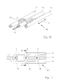
- FIG. 10 is a perspective view of a detail of an electrode belt with three strands (tubes).
- FIG. 11 is a top view of the electrode belt according to FIG. 10 ;
- FIG. 12 is a sectional view along the section line B-B of the electrode belt according to FIG. 11 ;
- FIG. 13 is a view showing examples of folded electrode feed lines
- FIG. 14 is a top view of a belt segment of an electrode belt
- FIG. 15 is a side view of the belt segment according to FIG. 14 in the direction of view C;
- FIG. 16 is a schematic view of an alternative embodiment of the electrode belt according to FIG. 11 with a gel pad;
- FIG. 17 is a side view of the electrode belt according to FIG. 16 ;
- FIG. 18 is a schematic diagram showing an electrode belt and an evaluating unit with wireless communication.
- FIG. 1 schematically shows an electrode belt 1 for electrical impedance tomography with 16 electrodes 2 on an elastic electrode holder 3 made of silicone.
- the 16 electrodes 2 are designated by the numbers 1-16.
- Electrode feed lines extend within the electrode holder 3 .
- the electrode feed lines are not specifically shown in FIG. 1 .
- the electrode feed lines are connected to a feed line (primary connection line) 6 at a feed point (primary connection site) 4 , at which a belt closure 5 is located.
- the feed line 6 is connected to an evaluating unit 10 , in which all the calculations necessary for the impedance tomography are performed.
- the electrode belt 1 is placed around the upper body of a test subject, not specifically shown in FIG. 1 .
- the electrode belt 1 can be opened at the belt closure 5 .
- the belt closure 5 establishes both a mechanical connection and an electrical connection, because eight electrode feed lines each, indicated by arrows 11 , 12 , extend to the electrodes 2 , starting from the belt closure 5 .
- the electrodes are arranged at equal distance from each other.
- a reference electrode 13 which is likewise fastened to the test subject's body at the distance D relative to the electrode belt 1 , is located above the electrode belt 1 .
- FIG. 2 shows an alternative embodiment of an electrode belt 101 , which has, unlike the electrode belt 1 according to FIG. 1 , two feed lines 61 , 62 , which are connected separately by a belt closure 51 with an electrode holder 31 . Starting from the feed points 41 , 42 of the feed lines 61 , 62 , up to four electrode feed lines extend to the electrodes 2 along the arrows 14 , 15 . Identical components are designated by the same reference numbers as in FIG. 1 .
- the feed lines 61 , 62 are connected with a belt closure 52 , 53 each in the electrode belt 102 according to FIG. 3 . Because of the two belt closures 52 , 53 , the electrode belt 102 comprises a first belt segment 33 and a second belt segment 34 , each with an equal number of electrodes 2 .
- the electrode belt 103 according to FIG. 4 differs from the electrode belt 101 according to FIG. 2 by an additional belt closure 54 , by which two belt segments 35 , 36 with equal numbers of electrodes 2 are formed.
- FIG. 5 schematically shows an electrode belt 104 lying on the sternal depression 70 of a test subject 71 .
- two electrodes 21 , 22 are provided, which are arranged adjacent to each other, bulge forward and lead to a radial force component when the electrode belt 104 is put in place.
- FIG. 6 illustrates the coverage of the spinal depression 72 of the test subject 71 with an electrode belt 105 , in which shaped elements incorporated in the belt 105 in the form of bead-like projections 73 , 74 are used as a padding for the electrodes 2 .
- FIG. 7 shows a top view of the electrode belt 103 according to FIG. 4 with the belt segments 35 , 36 and the belt closures 51 , 54 .
- the feed lines 61 , 62 lead directly to the electrode feed lines 63 , which, starting from the feed points 41 , 42 , extend directly to the electrodes 2 .
- FIG. 8 shows an enlarged detail E of the electrode belt 103 according to FIG. 7 with the belt closure 51 .
- the belt closure 51 comprises two straps 55 , 56 , which can be displaced in relation to one another, wherein a first strap 55 has two tapering elongated holes 57 , and a second strap 56 has rivets 58 .
- the diameter of the rivets 58 is selected to be such that the rivets can be introduced into the elongated holes at the point where the elongated holes have the greatest internal diameter.
- FIG. 9 shows a sectional view of the electrode belt 103 in the area of the belt closure 51 along the section line A-A.
- FIG. 10 shows a perspective view of an electrode belt 106 , which comprises three strands (tubes) 75 , 76 , 77 , which extend in parallel and are connected to one another section by section via cross struts (tube mounting piece) 78 .
- the electrodes 2 are located in the middle on the cross struts 78 .
- the two outer strands 75 , 77 are made of an elastic solid material, whereas the middle strand 76 , though also elastic, is hollow on the inside, so that it can accommodate electrode feed lines 63 .
- the direction of stretching of the electrode belt 106 is illustrated by the double arrow 16 .
- FIG. 11 shows a top view of the electrode belt 106 with cross struts 78 , which are located next to each other and are arranged at equal distances from each other.
- FIG. 12 shows a sectional view of the electrode belt 106 according to FIG. 11 along a section line B-B.
- the electrode 2 is fastened to an elastic membrane 79 according to this embodiment.
- the elastic membrane 79 closes off a cavity 80 .
- the individual cavities 80 can be put under pressure centrally via the middle strand 76 , and the membranes 79 bulge outwardly.
- the pressing pressure of the electrodes 2 on the test subject's body can be affected by changing the pressure.
- the latter are folded within the middle strand 76 in a triangular, loop-like or meandering pattern, as can be determined from FIG. 13 .
- FIG. 14 shows an electrode belt 107 , which comprises two belt segments 37 of identical design with eight electrodes 2 each. Only one belt segment 37 is shown in FIG. 14 for the sake of greater clarity.
- the belt segment 37 has two outer strands 86 , 87 , which consist of an elastic solid material, and a middle, hollow strand 88 , which is used to accommodate the electrode feed lines 63 .
- Plug-in straps 89 , 90 which act as feed points and have four plug type connections 91 , 92 each for contacting four electrodes 2 , are located at the ends of the belt segment 37 .
- Two plugs 93 , 94 with feed lines 64 , 65 for the electrodes 2 of the belt segment 37 have two rows located in parallel with contact pins 95 , 96 , which can be connected to the plug type connections 91 , 92 .
- the belt segment 37 is connected to the plugs 93 , 94 both mechanically and electrically with the contact pins 95 , 96 and the plug type connections 91 , 92 .
- a second belt segment 37 is connected to the two free contact pins 95 , 96 of the plugs 93 , 94 .
- the complete electrode belt 107 is obtained with two belt segments 37 and the plugs 93 , 94 .
- the plugs 93 , 94 combined with plug type straps 89 , 90 , form the belt closures 59 , 60 of the electrode belt 107 .
- FIG. 15 shows a side view of the electrode belt 107 in the direction of view C according to FIG. 14 .
- Identical components are designated by the same reference numbers as in FIG. 14 .
- the electrodes 2 are arranged at equal distances from each other on the belt segment 37 .
- the electrodes 2 in the area of the middle of the belt have shaped elements 97 , 98 as a padding in order to achieve good contacting in the chest or back regions.
- FIG. 16 shows an alternative embodiment of the electrode belt 106 according to FIG. 11 .
- the electrodes 2 located adjacent to each other have as the shaped element a gel pad 99 , which is clamped between the outer strands 75 , 77 and the middle strand 76 .
- FIG. 16 shows a top view of the electrode belt 106 , in which the electrodes are concealed.
- FIG. 17 shows a side view of the electrode belt 106 according to FIG. 16 , which is in contact with the sternal depression 70 of the test subject 71 .
- a radial force is applied to the middle strand 76 by the outer strands 75 , 77 , as a result of which the electrodes 2 are pressed onto the sternal depression 70 .
- FIG. 18 shows the concept of the wireless connection of an electrode belt 1 to an evaluating unit 10 .
- an analog and digital electronic unit 82 is accommodated together with a transmitter-receiver 83 in a housing 84 located near the test subject.
- the electronic components accommodated within the housing 84 are supplied with electricity by a separate power supply unit.
- the analog and digital electronic unit 82 is preferably designed for low energy consumption, as a result of which batteries can be used as the power supply.
- two sets of batteries are used, which can be removed one by one by means of a suitable mechanical or electromechanical change closure and recharged in an external charging station. It is thus not necessary to interrupt the measuring operation during the battery change.
- a transmitter-receiver 85 which receives the measured signals of the electrode belt 1 , is likewise located in front of the evaluating unit 10 .
- the wireless communication takes place via an infrared transmission link or a radio link with low output. Due to the wireless connection of the electrode belt 1 to the evaluating unit 10 , the evaluating unit 10 can be placed in a site-independent manner from the test subject interface, and long cable connections, which are, moreover, prone to fault, are avoided.
- the electrode belt 1 has, moreover, a coding means 81 in the form of an EEPROM, which is activated when the feed line 6 is connected. It is thus possible to recognize whether the correct electrode belt 1 is connected to the evaluating unit 10 .
Abstract
Description
Claims (31)
Applications Claiming Priority (2)
| Application Number | Priority Date | Filing Date | Title |
|---|---|---|---|
| DE10315863A DE10315863B4 (en) | 2003-04-08 | 2003-04-08 | electrode belt |
| DE10315863.4 | 2003-04-08 |
Publications (2)
| Publication Number | Publication Date |
|---|---|
| US20040260167A1 US20040260167A1 (en) | 2004-12-23 |
| US7315754B2 true US7315754B2 (en) | 2008-01-01 |
Family
ID=32319156
Family Applications (1)
| Application Number | Title | Priority Date | Filing Date |
|---|---|---|---|
| US10/766,705 Expired - Fee Related US7315754B2 (en) | 2003-04-08 | 2004-01-27 | Electrode belt |
Country Status (3)
| Country | Link |
|---|---|
| US (1) | US7315754B2 (en) |
| DE (1) | DE10315863B4 (en) |
| GB (1) | GB2400915B (en) |
Cited By (9)
| Publication number | Priority date | Publication date | Assignee | Title |
|---|---|---|---|---|
| US20080103021A1 (en) * | 2006-10-30 | 2008-05-01 | Forhouse Corporation | Guiding structure of a treadmill for guiding electrostatic charges of a human body |
| US20090227857A1 (en) * | 2008-03-06 | 2009-09-10 | Chuck Rowe | Biomedical electrode |
| US20100130847A1 (en) * | 2008-11-21 | 2010-05-27 | Tyco Healthcare Group Lp | Electrode Garment |
| US20100198100A1 (en) * | 2007-07-19 | 2010-08-05 | Omron Healthcare Co., Ltd. | Bioelectrical impedance measurement body attachment unit and body fat measurement device |
| US20110130640A1 (en) * | 2008-03-06 | 2011-06-02 | Tyco Healthcare Group Lp | Electrode Capable of Attachment to a Garment, System, and Methods of Manufacturing |
| WO2012006753A1 (en) | 2010-07-16 | 2012-01-19 | Swisstom Ag | Electrode sensor and use of electrode sensor as eit electrode |
| US20120271193A1 (en) * | 2011-04-23 | 2012-10-25 | Drager Medical Gmbh | Device and method for electroimpedance tomography |
| US20130053674A1 (en) * | 2010-03-03 | 2013-02-28 | Monica Ann Volker | Electrocardiogram monitoring devices |
| US10495669B2 (en) | 2013-08-22 | 2019-12-03 | Ford Global Technologies, Llc | Sensor for contactless electrocardiographic measurement |
Families Citing this family (50)
| Publication number | Priority date | Publication date | Assignee | Title |
|---|---|---|---|---|
| AUPQ113799A0 (en) | 1999-06-22 | 1999-07-15 | University Of Queensland, The | A method and device for measuring lymphoedema |
| DE102004028359B4 (en) * | 2004-06-11 | 2007-09-13 | Drägerwerk AG | Device for measuring body core temperature |
| US8068906B2 (en) * | 2004-06-21 | 2011-11-29 | Aorora Technologies Pty Ltd | Cardiac monitoring system |
| EP1768552A4 (en) * | 2004-06-21 | 2009-06-03 | Aorora Technologies Pty Ltd | Cardiac monitoring system |
| US20060084855A1 (en) * | 2004-10-20 | 2006-04-20 | Drager Medical Ag & Co. Kgaa | Electrode belt for carrying out electrodiagnostic procedures on the human body |
| KR20060040500A (en) * | 2004-11-06 | 2006-05-10 | 삼성전자주식회사 | Method and appratus for measuring bio signal |
| AU2006265763B2 (en) | 2005-07-01 | 2012-08-09 | Impedimed Limited | Monitoring system |
| JP5607300B2 (en) | 2005-07-01 | 2014-10-15 | インぺディメッド リミテッド | Apparatus and method for performing impedance measurements on an object |
| EP2250963A3 (en) * | 2005-07-01 | 2012-02-29 | Intersection Medical, Inc. | Pulmonary monitoring system |
| GB0519836D0 (en) * | 2005-09-29 | 2005-11-09 | Smartlife Technology Ltd | Contact sensors |
| CA2625631C (en) | 2005-10-11 | 2016-11-29 | Impedance Cardiology Systems, Inc. | Hydration status monitoring |
| US9060705B2 (en) * | 2005-12-20 | 2015-06-23 | Autopoiese Participacoes, Ltda | Electrode assembly for electrical impedance tomography |
| US8768429B2 (en) * | 2005-12-23 | 2014-07-01 | E.I.T. Pty Ltd. | Internal bleeding detection apparatus |
| ES2545730T3 (en) | 2006-05-30 | 2015-09-15 | Impedimed Limited | Impedance measurements |
| FR2906612B1 (en) * | 2006-09-28 | 2009-03-06 | Centre Nat Rech Scient | METHOD AND DEVICE FOR TOMOGRAPHY BY ELECTRIC IMPEDANCE. |
| WO2008064426A1 (en) | 2006-11-30 | 2008-06-05 | Impedimed Limited | Measurement apparatus |
| US10307074B2 (en) | 2007-04-20 | 2019-06-04 | Impedimed Limited | Monitoring system and probe |
| WO2009018620A1 (en) | 2007-08-09 | 2009-02-12 | Impedimed Limited | Impedance measurement process |
| US20110007937A1 (en) * | 2008-03-27 | 2011-01-13 | Koninklijke Philips Electronics N.V. | Method and system for measuring an object of interest |
| AU2009321478B2 (en) | 2008-11-28 | 2014-01-23 | Impedimed Limited | Impedance measurement process |
| JP5643829B2 (en) | 2009-10-26 | 2014-12-17 | インぺディメッド リミテッドImpedimed Limited | Method and apparatus for use in impedance measurement analysis |
| EP2501283B1 (en) | 2009-11-18 | 2016-09-21 | Impedimed Limited | Signal distribution for patient-electrode measurements |
| WO2012045188A1 (en) * | 2010-10-07 | 2012-04-12 | Swisstom Ag | Sensor device for electrical impedance tomography imaging, electrical impedance tomography imaging intrument and electrical impeance tomography method |
| US10362968B2 (en) * | 2010-10-15 | 2019-07-30 | Fresenius Medical Care Holdings, Inc. | Bioimpedance circumference measurement |
| DE102011018470B4 (en) * | 2011-04-18 | 2013-01-10 | Otto Bock Healthcare Gmbh | Bandage and electrode system |
| CN102217933A (en) * | 2011-06-10 | 2011-10-19 | 中国人民解放军第四军医大学 | Electrode placing device of electrical impedance tomography |
| WO2013075270A1 (en) * | 2011-11-25 | 2013-05-30 | Yang Chang-Ming | Object, method, and system for detecting heartbeat or whether or not electrodes are in proper contact |
| WO2013090798A1 (en) | 2011-12-14 | 2013-06-20 | Intersection Medical, Inc. | Devices, systems and methods for determining the relative spatial change in subsurface resistivities across frequencies in tissue |
| BR112014017767A8 (en) | 2012-01-27 | 2017-07-11 | Swisstom Ag | ELECTRODE IMPEDANCE MEASUREMENT STRAP, METHOD FOR ELECTRODE IMPEDANCE MEASUREMENT, AND, USE OF AN ELECTRODE IMPEDANCE STRAP |
| DE102012003229A1 (en) | 2012-02-20 | 2013-08-22 | Fachhochschule Lübeck | Measuring device for electrical impedance tomography, has several active electrodes that are interconnected to reference potential and voltage measurement point and power supply at different respective states during measuring process |
| WO2013177126A2 (en) * | 2012-05-21 | 2013-11-28 | General Electric Company | Electrode assembly |
| US11033235B2 (en) * | 2013-06-19 | 2021-06-15 | Nimbleheart Inc. | Method and apparatus for motion artifact reduction in ECG harness |
| FI124901B (en) * | 2013-07-18 | 2015-03-13 | Framgo Oy | Method and apparatus for determining body composition |
| DE102013216684B4 (en) * | 2013-08-22 | 2017-09-28 | Ford Global Technologies, Llc | Sensor for contactless electrocardiographic measurement, sensor array and seat or couch |
| EP3052018B1 (en) * | 2013-10-04 | 2020-04-15 | SenTec AG | An electrical impedance tomography system |
| CN103876738B (en) * | 2014-04-03 | 2016-03-09 | 思澜科技(成都)有限公司 | Based on the biological impedance probe of spectral characteristic, measuring system and method |
| BR102014031272A2 (en) * | 2014-12-12 | 2016-06-14 | Timpel Sa | electrode strap adjusting device |
| BR102014031270A2 (en) * | 2014-12-12 | 2016-06-14 | Timpel Sa | electrode strap |
| BR102014031274A2 (en) * | 2014-12-12 | 2016-06-14 | Timpel Sa | electrode module housing |
| FR3041429B1 (en) * | 2015-09-18 | 2020-03-27 | Electricite De France | BELT FOR MEASURING PHYSICAL QUANTITIES OF AN OBJECT |
| RU2663539C2 (en) * | 2016-06-22 | 2018-08-07 | Общество с ограниченной ответственностью "Кардиотехника" | Device for transmission of biophysiological signals |
| JP6725878B2 (en) * | 2016-07-11 | 2020-07-22 | Smk株式会社 | Biomedical electrode and garment with biomedical electrode |
| CN107811616B (en) * | 2016-09-14 | 2021-01-15 | 中国科学院宁波材料技术与工程研究所 | Flexible multi-parameter human body sign detector and use method thereof |
| WO2018085951A1 (en) * | 2016-11-11 | 2018-05-17 | Swisstom Ag | Sensor belt and positioning aid fol electro-imfedance tomography imaging in neonates |
| PL423839A1 (en) * | 2017-12-11 | 2019-06-17 | Netrix Spółka Akcyjna | Measuring electrode with fastening, for application in the electric impedance tomography |
| SG11202009603YA (en) * | 2018-03-29 | 2020-10-29 | Wear Future Technologies Co Ltd | Neck massager |
| DE102019127041A1 (en) * | 2019-10-08 | 2021-04-08 | Otto-Von-Guericke-Universität Magdeburg | Clinical monitoring device |
| NL2026207B1 (en) * | 2020-08-04 | 2022-04-08 | Bambi Belt Holding B V | System for monitoring one or more vital signs of a human body, in particular a baby, as well as a method of pairing system elements. |
| RU2757963C1 (en) * | 2020-11-25 | 2021-10-25 | Акционерное общество "Производственное объединение "Уральский оптико-механический завод" имени Э.С. Яламова" (АО "ПО "УОМЗ") | Modular electrode system for three-dimensional electrical impedance tomography |
| RU203887U1 (en) * | 2020-12-23 | 2021-04-26 | Алексей Витальевич Русскин | ELECTRODE DEVICE FOR REGISTRATION OF BIOELECTRIC POTENTIALS OF HUMAN SURFACE SURFACE |
Citations (17)
| Publication number | Priority date | Publication date | Assignee | Title |
|---|---|---|---|---|
| US4202344A (en) * | 1976-10-05 | 1980-05-13 | Harold Mills | Electrocardiograph electrodes and associated assemblies |
| US4308872A (en) * | 1977-04-07 | 1982-01-05 | Respitrace Corporation | Method and apparatus for monitoring respiration |
| US4539640A (en) * | 1982-01-12 | 1985-09-03 | Tasc Ltd. | Reconstruction system and methods for impedance imaging |
| US4681118A (en) * | 1984-06-11 | 1987-07-21 | Fukuda Denshi Co., Ltd. | Waterproof electrode assembly with transmitter for recording electrocardiogram |
| US4751928A (en) * | 1986-06-11 | 1988-06-21 | Slovenska Akdemie Vied Bratislava | Multielectrode system for surface registering of electric heart potentials |
| US4807640A (en) * | 1986-11-19 | 1989-02-28 | Respitrace Corporation | Stretchable band-type transducer particularly suited for respiration monitoring apparatus |
| US5191886A (en) * | 1991-04-18 | 1993-03-09 | Physio-Control Corporation | Multiple electrode strip |
| US5313952A (en) * | 1992-09-23 | 1994-05-24 | Hoch Richard W | Electrode attachment apparatus |
| US5353793A (en) * | 1991-11-25 | 1994-10-11 | Oishi-Kogyo Company | Sensor apparatus |
| US5782238A (en) * | 1995-11-27 | 1998-07-21 | Beitler; Martin M. | Multiple electrode EKG device |
| EP1000580A1 (en) | 1998-11-11 | 2000-05-17 | Siemens-Elema AB | Electrical impedance tomography system |
| US6205346B1 (en) * | 1995-10-19 | 2001-03-20 | Tapuz Medical Technology, Ltd. | Electrodes apron for ECG |
| US6353396B1 (en) * | 1996-07-14 | 2002-03-05 | Atlas Researches Ltd. | Method and apparatus for monitoring states of consciousness, drowsiness, distress, and performance |
| US20020097155A1 (en) * | 2001-01-23 | 2002-07-25 | Cassel Cynthia L. | Combination breathing monitor alarm and audio baby alarm |
| US6461307B1 (en) * | 2000-09-13 | 2002-10-08 | Flaga Hf | Disposable sensor for measuring respiration |
| US20040097839A1 (en) * | 2002-07-03 | 2004-05-20 | Epley Research, L.L.C. | Head-stabilized medical apparatus, system and methodology |
| US20040236202A1 (en) * | 2003-05-22 | 2004-11-25 | Burton Steven Angell | Expandable strap for use in electrical impedance tomography |
Family Cites Families (12)
| Publication number | Priority date | Publication date | Assignee | Title |
|---|---|---|---|---|
| US4121575A (en) * | 1976-10-05 | 1978-10-24 | Harold Mills | Devices for rapid placement and recording of ECG precordial leads in patients |
| GB8309927D0 (en) * | 1983-04-13 | 1983-05-18 | Smith D N | Determination of internal structure of bounded objects |
| US4709704A (en) * | 1984-03-06 | 1987-12-01 | The Kendall Company | Monitoring device for bio-signals |
| CA1270357A (en) * | 1986-02-18 | 1990-06-19 | Gregory Allan Chapman | Automatic transfer apparatus |
| US5341806A (en) * | 1991-04-18 | 1994-08-30 | Physio-Control Corporation | Multiple electrode strip |
| JP3759606B2 (en) * | 1994-03-11 | 2006-03-29 | ビーティージー・インターナショナル・リミテッド | Electrical impedance tomography |
| US5919142A (en) * | 1995-06-22 | 1999-07-06 | Btg International Limited | Electrical impedance tomography method and apparatus |
| CA2191285A1 (en) * | 1996-11-26 | 1998-05-26 | Philip Maurice Church | Electrode arrangement for electrical impedance tomography system |
| US6122544A (en) * | 1998-05-01 | 2000-09-19 | Organ; Leslie William | Electrical impedance method and apparatus for detecting and diagnosing diseases |
| ES2199759T3 (en) * | 1999-01-11 | 2004-03-01 | Bmr Research And Development Limited | ELECTROTHERAPY DEVICE. |
| DE10238310A1 (en) * | 2002-08-21 | 2004-03-04 | Erich Jaeger Gmbh | electrode assembly |
| DE10301202B3 (en) * | 2002-12-21 | 2004-01-22 | Dräger Medical AG & Co. KGaA | ventilation system |
-
2003
- 2003-04-08 DE DE10315863A patent/DE10315863B4/en not_active Expired - Fee Related
-
2004
- 2004-01-27 US US10/766,705 patent/US7315754B2/en not_active Expired - Fee Related
- 2004-04-07 GB GB0407917A patent/GB2400915B/en not_active Expired - Fee Related
Patent Citations (17)
| Publication number | Priority date | Publication date | Assignee | Title |
|---|---|---|---|---|
| US4202344A (en) * | 1976-10-05 | 1980-05-13 | Harold Mills | Electrocardiograph electrodes and associated assemblies |
| US4308872A (en) * | 1977-04-07 | 1982-01-05 | Respitrace Corporation | Method and apparatus for monitoring respiration |
| US4539640A (en) * | 1982-01-12 | 1985-09-03 | Tasc Ltd. | Reconstruction system and methods for impedance imaging |
| US4681118A (en) * | 1984-06-11 | 1987-07-21 | Fukuda Denshi Co., Ltd. | Waterproof electrode assembly with transmitter for recording electrocardiogram |
| US4751928A (en) * | 1986-06-11 | 1988-06-21 | Slovenska Akdemie Vied Bratislava | Multielectrode system for surface registering of electric heart potentials |
| US4807640A (en) * | 1986-11-19 | 1989-02-28 | Respitrace Corporation | Stretchable band-type transducer particularly suited for respiration monitoring apparatus |
| US5191886A (en) * | 1991-04-18 | 1993-03-09 | Physio-Control Corporation | Multiple electrode strip |
| US5353793A (en) * | 1991-11-25 | 1994-10-11 | Oishi-Kogyo Company | Sensor apparatus |
| US5313952A (en) * | 1992-09-23 | 1994-05-24 | Hoch Richard W | Electrode attachment apparatus |
| US6205346B1 (en) * | 1995-10-19 | 2001-03-20 | Tapuz Medical Technology, Ltd. | Electrodes apron for ECG |
| US5782238A (en) * | 1995-11-27 | 1998-07-21 | Beitler; Martin M. | Multiple electrode EKG device |
| US6353396B1 (en) * | 1996-07-14 | 2002-03-05 | Atlas Researches Ltd. | Method and apparatus for monitoring states of consciousness, drowsiness, distress, and performance |
| EP1000580A1 (en) | 1998-11-11 | 2000-05-17 | Siemens-Elema AB | Electrical impedance tomography system |
| US6461307B1 (en) * | 2000-09-13 | 2002-10-08 | Flaga Hf | Disposable sensor for measuring respiration |
| US20020097155A1 (en) * | 2001-01-23 | 2002-07-25 | Cassel Cynthia L. | Combination breathing monitor alarm and audio baby alarm |
| US20040097839A1 (en) * | 2002-07-03 | 2004-05-20 | Epley Research, L.L.C. | Head-stabilized medical apparatus, system and methodology |
| US20040236202A1 (en) * | 2003-05-22 | 2004-11-25 | Burton Steven Angell | Expandable strap for use in electrical impedance tomography |
Cited By (13)
| Publication number | Priority date | Publication date | Assignee | Title |
|---|---|---|---|---|
| US20080103021A1 (en) * | 2006-10-30 | 2008-05-01 | Forhouse Corporation | Guiding structure of a treadmill for guiding electrostatic charges of a human body |
| US20100198100A1 (en) * | 2007-07-19 | 2010-08-05 | Omron Healthcare Co., Ltd. | Bioelectrical impedance measurement body attachment unit and body fat measurement device |
| US8548558B2 (en) | 2008-03-06 | 2013-10-01 | Covidien Lp | Electrode capable of attachment to a garment, system, and methods of manufacturing |
| US20090227857A1 (en) * | 2008-03-06 | 2009-09-10 | Chuck Rowe | Biomedical electrode |
| US20110130640A1 (en) * | 2008-03-06 | 2011-06-02 | Tyco Healthcare Group Lp | Electrode Capable of Attachment to a Garment, System, and Methods of Manufacturing |
| US8868216B2 (en) | 2008-11-21 | 2014-10-21 | Covidien Lp | Electrode garment |
| US20100130847A1 (en) * | 2008-11-21 | 2010-05-27 | Tyco Healthcare Group Lp | Electrode Garment |
| US20130053674A1 (en) * | 2010-03-03 | 2013-02-28 | Monica Ann Volker | Electrocardiogram monitoring devices |
| WO2012006753A1 (en) | 2010-07-16 | 2012-01-19 | Swisstom Ag | Electrode sensor and use of electrode sensor as eit electrode |
| US10092211B2 (en) | 2010-07-16 | 2018-10-09 | Swisstom Ag | Electrode sensor and use of electrode sensor as EIT electrode |
| US20120271193A1 (en) * | 2011-04-23 | 2012-10-25 | Drager Medical Gmbh | Device and method for electroimpedance tomography |
| US9042957B2 (en) * | 2011-04-23 | 2015-05-26 | Dräger Medical GmbH | Device and method for electroimpedance tomography |
| US10495669B2 (en) | 2013-08-22 | 2019-12-03 | Ford Global Technologies, Llc | Sensor for contactless electrocardiographic measurement |
Also Published As
| Publication number | Publication date |
|---|---|
| DE10315863B4 (en) | 2013-03-14 |
| GB2400915A (en) | 2004-10-27 |
| US20040260167A1 (en) | 2004-12-23 |
| DE10315863A1 (en) | 2004-10-28 |
| GB2400915B (en) | 2005-07-27 |
| GB0407917D0 (en) | 2004-05-12 |
Similar Documents
| Publication | Publication Date | Title |
|---|---|---|
| US7315754B2 (en) | Electrode belt | |
| EP1494580B1 (en) | A wearable monitoring system and method of manufacturing of a wearable monitoring system | |
| CN102596021B (en) | Device for positioning electrodes on a user's scalp | |
| US20100049027A1 (en) | Electrode belt for carrying out electrodiagnostic procedures on the human body | |
| EP1494581B1 (en) | Monitoring system comprising electrodes with projections | |
| US4308870A (en) | Vital signs monitor | |
| US8708926B2 (en) | Double temperature sensor | |
| CN102497809B (en) | Electrode fixing device | |
| CN104382594B (en) | Electrode for encephalograms cap | |
| WO2015123157A1 (en) | Wearable sensor | |
| CN201675940U (en) | Electrode device | |
| CN211049350U (en) | Self-adaptive neural rehabilitation training head-mounted device | |
| JP6437138B2 (en) | Sensor unit | |
| CN207428499U (en) | A kind of intelligent back belt based on narrowband technology of Internet of things | |
| KR102541687B1 (en) | Pulsometer for newborns | |
| US11033235B2 (en) | Method and apparatus for motion artifact reduction in ECG harness | |
| CN209611127U (en) | Multi-functional health care patch | |
| US4852574A (en) | Electrocardiogram electrode pad | |
| KR20180079122A (en) | Headset for EEG Measure | |
| CN208677391U (en) | The brain wave acquisition device of Worn type | |
| CN109044016B (en) | Health sleep pillow and adjusting method thereof | |
| KR20210076523A (en) | EEG measurement head cap | |
| CN113017612B (en) | Lumbar joint mobility monitoring devices | |
| CN114391850B (en) | Electroencephalogram cap with force feedback self-adaptive contact effect adjustment function | |
| CN115192006B (en) | Film type local attaching device for monitoring chest and abdomen movement |
Legal Events
| Date | Code | Title | Description |
|---|---|---|---|
| AS | Assignment |
Owner name: DRAGER MEDICAL AG & CO. KGAA, GERMANY Free format text: ASSIGNMENT OF ASSIGNORS INTEREST;ASSIGNORS:LOENHARDT, STEFFEN;TESCHNER, ECKHARD;HAMPE, MARKUS;AND OTHERS;REEL/FRAME:014945/0423 Effective date: 20031219 |
|
| STCF | Information on status: patent grant |
Free format text: PATENTED CASE |
|
| AS | Assignment |
Owner name: DRAGER MEDICAL AG & CO. KG, GERMANY Free format text: CHANGE OF NAME;ASSIGNOR:DRAGER MEDICAL AG & CO. KGAA;REEL/FRAME:023196/0670 Effective date: 20051031 |
|
| AS | Assignment |
Owner name: DRAEGER MEDICAL GMBH, GERMANY Free format text: CHANGE OF NAME;ASSIGNOR:DRAEGER MEDICAL AG & CO. KG;REEL/FRAME:025137/0552 Effective date: 20100831 |
|
| FPAY | Fee payment |
Year of fee payment: 4 |
|
| FPAY | Fee payment |
Year of fee payment: 8 |
|
| AS | Assignment |
Owner name: DRAEGERWERK AG & CO. KGAA, GERMANY Free format text: MERGER;ASSIGNORS:DRAEGER MEDICAL GMBH;DRAEGERWERK AG & CO. KGAA;REEL/FRAME:036586/0718 Effective date: 20150603 |
|
| FEPP | Fee payment procedure |
Free format text: MAINTENANCE FEE REMINDER MAILED (ORIGINAL EVENT CODE: REM.); ENTITY STATUS OF PATENT OWNER: LARGE ENTITY |
|
| LAPS | Lapse for failure to pay maintenance fees |
Free format text: PATENT EXPIRED FOR FAILURE TO PAY MAINTENANCE FEES (ORIGINAL EVENT CODE: EXP.); ENTITY STATUS OF PATENT OWNER: LARGE ENTITY |
|
| STCH | Information on status: patent discontinuation |
Free format text: PATENT EXPIRED DUE TO NONPAYMENT OF MAINTENANCE FEES UNDER 37 CFR 1.362 |
|
| FP | Expired due to failure to pay maintenance fee |
Effective date: 20200101 |