US7321900B1 - Reducing memory requirements needed to represent XML entities - Google Patents
Reducing memory requirements needed to represent XML entities Download PDFInfo
- Publication number
- US7321900B1 US7321900B1 US10/173,466 US17346602A US7321900B1 US 7321900 B1 US7321900 B1 US 7321900B1 US 17346602 A US17346602 A US 17346602A US 7321900 B1 US7321900 B1 US 7321900B1
- Authority
- US
- United States
- Prior art keywords
- node
- data
- memory
- tree
- flag
- Prior art date
- Legal status (The legal status is an assumption and is not a legal conclusion. Google has not performed a legal analysis and makes no representation as to the accuracy of the status listed.)
- Expired - Lifetime, expires
Links
Images


Classifications
-
- G—PHYSICS
- G06—COMPUTING; CALCULATING OR COUNTING
- G06F—ELECTRIC DIGITAL DATA PROCESSING
- G06F16/00—Information retrieval; Database structures therefor; File system structures therefor
- G06F16/80—Information retrieval; Database structures therefor; File system structures therefor of semi-structured data, e.g. markup language structured data such as SGML, XML or HTML
- G06F16/83—Querying
-
- Y—GENERAL TAGGING OF NEW TECHNOLOGICAL DEVELOPMENTS; GENERAL TAGGING OF CROSS-SECTIONAL TECHNOLOGIES SPANNING OVER SEVERAL SECTIONS OF THE IPC; TECHNICAL SUBJECTS COVERED BY FORMER USPC CROSS-REFERENCE ART COLLECTIONS [XRACs] AND DIGESTS
- Y10—TECHNICAL SUBJECTS COVERED BY FORMER USPC
- Y10S—TECHNICAL SUBJECTS COVERED BY FORMER USPC CROSS-REFERENCE ART COLLECTIONS [XRACs] AND DIGESTS
- Y10S707/00—Data processing: database and file management or data structures
- Y10S707/99941—Database schema or data structure
- Y10S707/99944—Object-oriented database structure
-
- Y—GENERAL TAGGING OF NEW TECHNOLOGICAL DEVELOPMENTS; GENERAL TAGGING OF CROSS-SECTIONAL TECHNOLOGIES SPANNING OVER SEVERAL SECTIONS OF THE IPC; TECHNICAL SUBJECTS COVERED BY FORMER USPC CROSS-REFERENCE ART COLLECTIONS [XRACs] AND DIGESTS
- Y10—TECHNICAL SUBJECTS COVERED BY FORMER USPC
- Y10S—TECHNICAL SUBJECTS COVERED BY FORMER USPC CROSS-REFERENCE ART COLLECTIONS [XRACs] AND DIGESTS
- Y10S707/00—Data processing: database and file management or data structures
- Y10S707/99951—File or database maintenance
- Y10S707/99952—Coherency, e.g. same view to multiple users
- Y10S707/99953—Recoverability
Definitions
- the present invention relates to generating in-memory representations of XML entities, and in particular, to efficiently using memory to represent XML entities.
- XML describes and provides structure to a body of data, such as a file or data packet, referred to herein as an XML entity.
- the XML standard provides for tags that delimit the sections of an XML entity referred to as XML elements.
- Each XML element may contain a one or more name-value pairs referred to as attributes.
- the following XML Segment A is provided to illustrate XML.
- XML elements are delimited by a start tag and a corresponding end tag.
- segment A contains the start tag ⁇ Author> and the end tag ⁇ Author> to delimit an element.
- the data between the tags is referred to as the element's content.
- the content of the element is the text data Mark Berry.
- An element is herein referred to by its start tag.
- the element delimited by the start and end tags ⁇ publication> and ⁇ /publication> is referred to as the publication element.
- the book element is an example of an element that contains one or more elements. Specifically, book contains two elements: publication and author. An element that is contained by another element is referred to as a descendant of that element. Thus, the publication and author elements are descendants of the book element.
- the XML entity defines a hierarchical tree relationship between the element, its descendant elements, and its attribute.
- a set of elements that have such a hierarchical tree relationship is referred to herein as an XML tree.
- XML Document Object Model
- XML features such as tags and attribute names, allow users to search, sort, identify and extract data from XML entities.
- these features substantially inflate the amount of data needed to represent information in XML relative to the amount of data that would otherwise be required to merely record the information. This inflation can amount to an average increase of 400%.
- XML inflates the amount of data needed to represent information
- the amount of memory needed to store an in-memory representation of an XML tree can be relatively very large.
- the amount of memory needed for an in-memory representation of an XML entity can easily exceed available memory resources on a computer.
- Described herein are approaches that allow an XML entity to be accessed in a way that requires less memory. These approaches involve dynamically generating and maintaining an in-memory representation of only a portion of an XML tree.
- the in-memory representation of an XML tree is herein referred to as a node tree.
- the node tree contains data from the XML tree, and is generated by extracting data from a compressed form of an XML entity.
- the node tree contains information about the location of specific elements within the compressed XML entity.
- the approaches described herein allow an XML tree to be accessed without having to generate an in-memory representation of the whole XML tree, thus reducing the amount of memory needed to access the data in the XML tree.
- FIG. 1 is a block diagram of a node tree representing a portion of an XML tree defined by a compressed XML entity according to an embodiment of the present invention
- FIG. 2 is a block diagram of an XML entity and its compressed form according to an embodiment of the present invention
- FIG. 3 is a block diagram of a node tree representing a portion of an XML tree defined by a compressed XML entity according to an embodiment of the present invention
- FIG. 4 is a flowchart of a process that creates a node in a node tree according to an embodiment of the present invention
- FIG. 5 is a flowchart of a process for releasing a node from memory according to an embodiment of the present invention
- FIG. 6 is a flowchart of a process that creates a node in a node tree according to an embodiment of the present invention.
- FIG. 7 is a block diagram of a computer system that may be used to implement an embodiment of the present invention.
- Described herein are approaches that allow an XML entity to be accessed in a way that efficiently uses memory. These approaches involve dynamically generating and maintaining an in-memory representation of only a portion of an XML tree.
- the in-memory representation of an XML tree is herein referred to as a node tree.
- the node tree contains data from the XML tree, and is generated by extracting data from a compressed form of an XML entity.
- the node tree contains information about the location of specific elements within the compressed XML entity.
- the approaches described herein allow an XML tree to be accessed without having to generate an in-memory representation of the whole XML tree, thus reducing the amount of memory needed to access the data in the XML tree.
- FIG. 1 is a block diagram that depicts a node tree 101 .
- a node tree is a data structure that represents a set of entities and a hierarchical tree relationship between the set of entities, such as the XML elements in an XML entity.
- Node tree 101 represents a portion of the XML tree in XML compressed stream 150 .
- a node tree contains nodes. Nodes are data structures that represent an entity from the set of entities represented by the node tree.
- Each node in node tree 101 contains a reference or pointer to the node's corresponding XML element in XML compressed stream 150 .
- each node in node tree 101 contains one or more links to another node. The links represent hierarchical tree relationships between the elements of the XML tree in XML compressed stream 150 .
- Hierarchical tree relationships between entities and in particular, elements and nodes that represent them in a node tree.
- the hierarchical relationship between nodes in a node tree are defined by the hierarchical relationships between the entities those nodes represent.
- the terms are illustrated using elements in segment A and node tree 101 .
- Parent The term parent is used to refer to an entity that is an immediate ascendant in a hierarchical tree relationship.
- the element book is the parent of publication and author.
- Node 130 represents a parent element whose child elements are represented by node 132 and 134 .
- Node 130 is the parent of nodes 132 and 134 .
- Child The term child is used to refer to an entity that is an immediate descendant in a hierarchical tree relationship.
- the element publication and author are each a child of the element book.
- Nodes 132 and 134 each represent a child element whose parent element is represented by node 130 .
- Nodes 132 and 134 are each a child of node 130 .
- First and last child The children of a parent are associated with a “sibling order”.
- the first child is the first child based in the sibling order and the last child is the last child in the sibling order.
- the sibling order is based on the order in which the children are defined in the parent element. For example, with respect to book, publication is the first child and author is the last child.
- Node 132 represents the first child of the parent element represented by node 130
- node 134 represents the last child of the parent element. Node 132 is referred as the first child with respect to node 130 and node 134 as the last child.
- next sibling of a child element is the next sibling in the sibling order of the children of the parent element.
- the previous sibling of a child element is the previous sibling in the sibling order.
- Node 134 represents the next sibling of the element represented by node 132 .
- Node 134 is node 132 's next sibling.
- Node 132 represents the previous sibling of the element represented by node 134 .
- Node 132 is node 134 's previous sibling.
- Immediate Relative An immediate relative of a node is either the parent, child, next or previous sibling of the node.
- XML compressed stream 150 is accessed through an Application Programming Interface (“API”) 160 .
- An API is a set of functions (e.g. object methods) that provide a particular service. In the case of API 160 , that service is to provide access to an XML tree. As the functions of API 160 are invoked to access XML compressed stream 150 , the nodes are created as needed to store and access data from XML compressed stream 150 .
- API 160 is associated with a current node. Many functions of API 160 request one or more nodes that have a particular hierarchical tree relationship with the current node. The following is an illustrative set of functions in API 160 .
- GetFirstChild( ) retrieves the first child of the current node, that is the element corresponding to the first child of the current node. Sets the current node to the first child.
- GetLastChild( ) retrieves the last child of the current node and sets the current node to the last child.
- GetNextSibling( ) retrieves the next sibling of the current node. Sets the current node to the next sibling.
- GetPreviousSibling( ) retrieves the previous sibling of the current node. Sets the current node to the previous sibling.
- GetChildren( ) Loads all children of parent node into memory.
- flags are maintained in the nodes.
- the flags indicate whether a node that has a particular relationship currently resides in memory.
- the flags may be examined to efficiently determine whether a node is in memory or not.
- the memory allotted to storing nodes is finite. As nodes are loaded into memory, eventually all the memory used for storing the nodes is used. When this occurs, to load a node into memory, the memory used to store another node's data is overwritten or replaced with the data of the node to be loaded. When the data of a node is stored in place of another node, the other node is referred to herein as being released.
- XML stream 150 may be too large to fit completely into memory allotted for it. Therefore, portions of compress XML entity 150 may be stored in one or more cache buffers. Portions of XML stream 150 are swapped in and out of the buffers using cache management techniques.
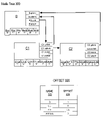
- FIG. 2 is a block diagram depicting an XML entity and its compressed form, which are used to illustrate embodiments of the present invention. Referring to FIG. 2 , it shows XML entity 202 , and its compressed form, compressed XML entity 204 .
- XML entity 202 preferably conforms to the DOM standard.
- XML entity 202 contains elements b, c 1 , c 2 , and attr 1 .
- Element b contains attribute attr 1 .
- Elements c 1 and c 2 are empty elements, which do not require end tags.
- XML entity 202 defines an XML tree with b as the root element and elements c 1 and c 2 as child elements of element b.
- Compressed XML entity 204 includes two components: XML compressed stream 210 and token table 220 .
- XML compressed stream 210 is data that represents an XML entity using element tags and tokens in place of start and end tags.
- An element tag is a delimiter that demarcates the beginning of an element.
- a token is a value that identifies an element or attribute name in the XML entity.
- XML compressed stream 210 includes element tags ET 1 , ET 2 , and ET 3 , and tokens 1 , 2 , 3 , and 4 .
- Compressed stream 210 uses less data then the XML entity it represents, for several reasons.
- a start and/or an endtag are replaced by an element tag and token, which may be represented using a lesser amount of data than a start tag and end tag.
- an element and token may each be represented by a byte, while each start tag and end tag in XML entity 202 uses multiple bytes to represent multiple characters, e.g., ⁇ a> and ⁇ /a>.
- a token uses less amount of data to represent an attribute name.
- Token table 220 is a table that maps attributes and elements to tokens. Token table 220 includes columns name 222 and token 224 . Column name 222 contains element names and attribute names, and column token 224 contains tokens. Each row in token table 220 maps an element or attribute to a token. The first row in token table 220 maps element b to token 1 , the second row element c 1 to token 2 , the third c 2 to 3 , and the fourth attribute attr 1 to 4 .
- FIG. 3 shows node tree 300 , a node tree used to illustrate an embodiment of the present invention.
- Node tree 300 represents the XML tree defined by XML entity 202 .
- Node tree 300 includes nodes B, C 1 , and C 2 , which each represent elements b, c 1 , and c 2 .
- Each node in node tree 300 contains links to another node.
- a link is, for example, a memory pointer or reference to another node.
- Each link represents a hierarchical tree relationship between the elements represented by the nodes.
- node B contains links B.ptlink, B.sblink, and B.fclink.
- B.ptlink is a parent link which refers to the parent of node B.
- B.ptlink does not refer to any node because element b is a root node with no parent.
- B.fclink is a first child link.
- a first child link refers to a node's first child.
- Link B.fclink refers to node C 1 , which represents the first child element of A.
- B.sblink is a sibling link.
- a sibling link refers to a node's next sibling. In this case, link B.sblink does not refer to any node.
- Node C 1 includes a parent link, sibling link, and first child link. These links are C 1 .ptlink, C 1 .sblink, and C 1 .fclink, respectively.
- C 1 .ptlink refers to node B.
- C 1 .fclink does not refer to any link.
- C 1 .sblink refers to node C 2 .
- Node C 2 includes a parent link, sibling link, and first child link. These links are C 2 .ptlink, C 2 .sblink, and C 2 .fclink, respectively.
- C 2 .ptlink refers to node B.
- C 2 .fclink and C 2 .sblink does not refer to any node.
- Each node contains a “stream pointer”.
- Node B contains stream pointer B.strpbr
- node C 1 contains C 1 .strptr
- node C 2 contains C 2 .strptr.
- a stream pointer points to the beginning location of a node's element in a compressed stream.
- C 1 .strptr contains the offset value 9, indicating the number of bytes, inclusively, between the first byte of XML compressed stream 210 and the first byte of element C 1 in the compressed stream.
- B.strptr contains the offset value 1 and C 2 .strptr the offset value 11.
- the offset value stored in the stream pointer of a node is referred to herein as the node's offset.
- Each node contains a set of flags that indicate whether a node that has a particular hierarchical tree relationship with the node has been loaded into memory.
- This set of flags includes the following.
- First child flag indicates whether a node's first child resides in memory. Nodes B, C 1 , and C 2 contain first child flags B.fc, C 1 .fc, and C 2 .fc, respectively. The first child flag is set when a node is created during execution of the GetFirstChild( ) function.
- Last child flag indicates whether a node's last child resides in memory. Nodes B, C 1 , and C 2 contain last child flags B.lc, C 1 .lc, and C 2 .lc, respectively. The last child flag is set when a node is created during execution of the GetLastChild( ) function.
- Attribute flag indicates whether the node's attribute nodes reside in memory. Nodes B, C 1 , and C 2 contain attribute flags B.ab, C 1 .ab, and C 2 .ab, respectively.
- Previous sibling flag indicates whether a node's previous sibling resides in memory. Nodes B, C 1 , and C 2 contain previous sibling flags B.ps, C 1 .ps, and C 2 .ps, respectively.
- next sibling flag indicates whether a node's next sibling resides in memory.
- Nodes B, C 1 , and C 2 contain next sibling flags B.ns, C 1 .ns, and C 2 .ns, respectively.
- Node tree 300 contains data structures which have not been depicted in FIG. 3 for purposes of exposition.
- a node may contain a link to another data structure that holds the text value of an element.
- a node may contain a link to a series of one or more linked nodes which hold attribute values for an element's attributes.
- Offset table 320 has two columns: name 322 and offset 324 .
- Name 322 contains element and attribute names and offset 324 contains offset values into XML compressed stream 210 .
- Each row in offset table 320 corresponds to an element or an attribute of an element loaded into memory, and maps the element or attribute to an offset value within XML compressed stream 210 .
- Offset table 320 maps element b to offset value 1, c 1 to offset value 9, c 2 to offset value 11, and attribute attr 1 to 3.
- FIG. 4 shows a process for loading a first child node, which is performed when executing the GetFirstChild( ) function. For purposes of illustration, it is presumed only node B of node tree 300 is loaded, and that offset table 320 contains only one row, which maps node b to offset value 1. Node B is the current node.
- step 412 it is determined whether the first child flag indicates that the first child node is loaded. If the first child flag does indicate that the first child flag is loaded, then execution of the steps proceeds to step 436 , where the remainder of the function is executed. Otherwise, execution proceeds to step 416 .
- the first child flag of node B, B.fc indicates that node B's first child has not been loaded. Hence, execution proceeds to step 416 .
- XML compressed stream 210 is parsed, beginning at the current nodes offset within the XML compressed stream 210 , to find the first child element within the current node.
- the first child element found is c 1 .
- the first child node is created and initialized, based on information parsed and extracted from the first child element found at step 416 .
- the step of creating and initializing the node includes setting the parent flag to TRUE and setting the parent link to refer to the parent node.
- its flags are initialized to a default value of FALSE. So the remaining flags in the node have a value of FALSE.
- any links are initialized so they do not refer to any node.
- node C 1 is created, c 1 .ptlink is set to refer to B, and C 1 .pt is set to TRUE.
- the current node is updated to reflect that its first child has been loaded.
- the first child flag is set to TRUE and the first child link is set to refer to the first child.
- B.fc is set to TRUE, and B.fclink is set to refer to node C 1 .
- a row for the just created node is added to the offset table 320 .
- a row mapping C 1 to its offset value of 9 is added to the offset table 320 .
- step 436 the execution of the function is completed. Operations performed at this step include setting the current node to the first child.
- the operations performed by the processes depicted for GetFirstChild( ) are illustrative of those performed by other functions and processes that create and initialize nodes, and, in particular, to those that are performed during the execution of other functions of API 160 .
- the links and flags of the current node are updated to reflect the newly created node.
- Nodes for attributes of an element may be created in several ways. When a node for an element is created, nodes for its attributes may also be created in memory. The nodes for the attributes are linked to the node for the element. In another embodiment, nodes for attributes are not loaded until requested via API 160 .
- FIG. 5 shows a process that is performed when releasing a first child node.
- nodes B, C 1 , and C 2 are loaded in memory as depicted in FIG. 3 .
- C 1 is the first child node being released.
- the parent node of the first child is updated to reflect that its first child has been released.
- the first child flag is set to FALSE and the first child link is set so that it no longer refers to a node.
- B.pt is set to FALSE and the B.fclink is set so that it no longer refers to a node.
- the next sibling node of the first child is updated to reflect that its previous sibling has been released.
- the previous sibling flag is set to FALSE and the previous sibling link is set to no longer refer to a node.
- C 2 .ps is set to FALSE and C 2 .pclink is set so that it no longer refers to a node.
- step 520 the row corresponding to the first child node in offset table 320 is marked to indicate that the node has been released. Execution of the steps ends.
- the process for releasing a first child is illustrative of processes that release nodes in general.
- nodes referred to by a link of the node to be released are updated to reflect that the node is no longer in memory.
- node C 1 After an element's node is released, another node for that element may be later loaded. When loaded, the other node's flags and links may not reflect that an immediate relative is currently loaded when in fact the immediate relative is. For example, after node C 1 in the previous example has been released, it is possible that the first child of node B may again be requested (by invoking GetFirstChild( )) before node C 2 is released. In this case, a node C 1 ′ is created using the process shown in FIG. 4 .
- the first child flag B.fc and the first child link B.fclink of node B reflect that node C 1 ′ is loaded, but the next sibling flag and next sibling link of C 1 ′ do not reflect that C 1 's next sibling, node C 2 , is loaded, when in fact it is.
- a dangling relative is used herein to refer to an immediate relative of a node, where the flags and links of the node do not reflect that the immediate relative is in memory when in fact it is.
- node C 2 is a dangling relative.
- duplicate nodes should not be created for elements already represented by a node in a node tree.
- mechanisms are needed to definitively detect whether a node for the element has already been loaded. While a node's flags may be used to indicate that an immediate relative is not in the cache, in some circumstances, as explained above, the flags may not be exclusively relied upon to definitely determine that an immediate relative does not reside in memory.
- a mechanism that accounts for dangling relatives. The following is an example of a process that uses such a mechanism.
- FIG. 6 is a process followed to execute GetNextSibling( ).
- the process accounts for dangling relatives, as is described in greater detail.
- the process is illustrated using node tree 300 .
- node C 1 is the current node
- node C 2 is a dangling relative with respect to node C 1 .
- C 1 .ns is set to FALSE and C 1 .sblink is not set to refer to any node.
- step 612 it is determined whether the next sibling flag indicates that the next sibling is in memory. If the next sibling flag does indicate that the next sibling flag is in memory, then execution of the steps proceeds to step 636 , where the remainder of the function is executed. Otherwise, execution proceeds to step 616 . In the current example, the next sibling flag of node C 1 , C 1 .ns, does not indicate that node C 1 's next sibling has been loaded. Hence, execution proceeds to step 616 .
- the XML compressed stream 210 is parsed, beginning at the current node's offset within the XML compressed stream 210 , to find the next sibling element.
- the next sibling element found is C 2 .
- step 618 it is determined whether or not the offset table 320 contains an entry for the next sibling element. If offset table 320 does contain such an entry, then a node for the next sibling element is already in memory. Execution of the steps flows to step 624 rather than 620 , thereby avoiding creating a duplicate node.
- the next sibling node is created and initialized, based on information parsed and extracted from the next sibling element found at step 616 .
- the step of creating and initializing the node includes setting the parent flag to TRUE, setting the parent link to the parent node, and setting the previous sibling flag to TRUE.
- the current node is updated to reflect that its next sibling is in memory.
- the next sibling flag is set to TRUE and the next sibling link is set to refer to node C 2 .
- the next sibling node is then updated to reflect that its previous sibling is in memory.
- the previous sibling flag is set to TRUE and the previous sibling link is set to refer to node C 1 .
- a row for the just created node is added to offset table 320 .
- the process executed for GetNextSibling( ) is but one example of a process that accounts for dangling relatives when creating nodes.
- Another example is GetLastChild( ).
- the reason for this is that a last child may be created when executing an API 160 function that does not set the last child flag, such as the function GetNextSibling( ).
- FIG. 6 when a sibling node is created, its parent node is not updated. If the created node is for a last child element, the created node is a dangling relative because its parent node's last child flag does not indicate that the last child is loaded.
- the present invention is not limited to generating node trees for data entities that conform to XML.
- the techniques for creating, maintaining, and storing node trees may be used for node trees that represent a portion of other types of bodies of data that contain data parts that are hierarchically related.
- element has been used to refer to elements of an XML entity, such use of the term element is not anyway intended to limit the semantic scope of the term to an XML element.
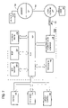
- FIG. 7 is a block diagram that illustrates a computer system 700 upon which an embodiment of the invention may be implemented.
- Computer system 700 includes a bus 702 or other communication mechanism for communicating information, and a processor 704 coupled with bus 702 for processing information.
- Computer system 700 also includes a main memory 706 , such as a random access memory (RAM) or other dynamic storage device, coupled to bus 702 for storing information and instructions to be executed by processor 704 .
- Main memory 706 also may be used for storing temporary variables or other intermediate information during execution of instructions to be executed by processor 704 .
- Computer system 700 further includes a read only memory (ROM) 708 or other static storage device coupled to bus 702 for storing static information and instructions for processor 704 .
- ROM read only memory
- a storage device 710 such as a magnetic disk or optical disk, is provided and coupled to bus 702 for storing information and instructions.
- Computer system 700 may be coupled via bus 702 to a display 712 , such as a cathode ray tube (CRT), for displaying information to a computer user.
- a display 712 such as a cathode ray tube (CRT)
- An input device 714 is coupled to bus 702 for communicating information and command selections to processor 704 .
- cursor control 716 is Another type of user input device
- cursor control 716 such as a mouse, a trackball, or cursor direction keys for communicating direction information and command selections to processor 704 and for controlling cursor movement on display 712 .
- This input device typically has two degrees of freedom in two axes, a first axis (e.g., x) and a second axis (e.g., y), that allows the device to specify positions in a plane.
- the invention is related to the use of computer system 700 for implementing the techniques described herein. According to one embodiment of the invention, those techniques are performed by computer system 700 in response to processor 704 executing one or more sequences of one or more instructions contained in main memory 706 . Such instructions may be read into main memory 706 from another computer-readable medium, such as storage device 710 . Execution of the sequences of instructions contained in main memory 706 causes processor 704 to perform the process steps described herein. In alternative embodiments, hard-wired circuitry may be used in place of or in combination with software instructions to implement the invention. Thus, embodiments of the invention are not limited to any specific combination of hardware circuitry and software.
- Non-volatile media includes, for example, optical or magnetic disks, such as storage device 710 .
- Volatile media includes dynamic memory, such as main memory 706 .
- Transmission media includes coaxial cables, copper wire and fiber optics, including the wires that comprise bus 702 . Transmission media can also take the form of acoustic or light waves, such as those generated during radio-wave and infra-red data communications.
- Computer-readable media include, for example, a floppy disk, a flexible disk, hard disk, magnetic tape, or any other magnetic medium, a CD-ROM, any other optical medium, punchcards, papertape, any other physical medium with patterns of holes, a RAM, a PROM, and EPROM, a FLASH-EPROM, any other memory chip or cartridge, a carrier wave as described hereinafter, or any other medium from which a computer can read.
- Various forms of computer readable media may be involved in carrying one or more sequences of one or more instructions to processor 704 for execution.
- the instructions may initially be carried on a magnetic disk of a remote computer.
- the remote computer can load the instructions into its dynamic memory and send the instructions over a telephone line using a modem.
- a modem local to computer system 700 can receive the data on the telephone line and use an infra-red transmitter to convert the data to an infra-red signal.
- An infra-red detector can receive the data carried in the infra-red signal and appropriate circuitry can place the data on bus 702 .
- Bus 702 carries the data to main memory 706 , from which processor 704 retrieves and executes the instructions.
- the instructions received by main memory 706 may optionally be stored on storage device 710 either before or after execution by processor 704 .
- Computer system 700 also includes a communication interface 718 coupled to bus 702 .
- Communication interface 718 provides a two-way data communication coupling to a network link 720 that is connected to a local network 722 .
- communication interface 718 may be an integrated services digital network (ISDN) card or a modem to provide a data communication connection to a corresponding type of telephone line.
- ISDN integrated services digital network
- communication interface 718 may be a local area network (LAN) card to provide a data communication connection to a compatible LAN.
- LAN local area network
- Wireless links may also be implemented.
- communication interface 718 sends and receives electrical, electromagnetic or optical signals that carry digital data streams representing various types of information.
- Network link 720 typically provides data communication through one or more networks to other data devices.
- network link 720 may provide a connection through local network 722 to a host computer 724 or to data equipment operated by an Internet Service Provider (ISP) 726 .
- ISP 726 in turn provides data communication services through the world wide packet data communication network now commonly referred to as the “Internet” 728 .
- Internet 728 uses electrical, electromagnetic or optical signals that carry digital data streams.
- the signals through the various networks and the signals on network link 720 and through communication interface 718 which carry the digital data to and from computer system 700 , are exemplary forms of carrier waves transporting the information.
- Computer system 700 can send messages and receive data, including program code, through the network(s), network link 720 and communication interface 718 .
- a server 730 might transmit a requested code for an application program through Internet 728 , ISP 726 , local network 722 and communication interface 718 .
- the received code may be executed by processor 704 as it is received, and/or stored in storage device 710 , or other non-volatile storage for later execution. In this manner, computer system 700 may obtain application code in the form of a carrier wave.
Abstract
Description
-
- <book>
- <publication publisher=“Doubleday”
- date=“January”></publication>
- <Author>Mark Berry</Author>
- <publication publisher=“Doubleday”
- </book>
- <book>
Claims (24)
Priority Applications (1)
| Application Number | Priority Date | Filing Date | Title |
|---|---|---|---|
| US10/173,466 US7321900B1 (en) | 2001-06-15 | 2002-06-14 | Reducing memory requirements needed to represent XML entities |
Applications Claiming Priority (3)
| Application Number | Priority Date | Filing Date | Title |
|---|---|---|---|
| US29843701P | 2001-06-15 | 2001-06-15 | |
| US38458302P | 2002-05-31 | 2002-05-31 | |
| US10/173,466 US7321900B1 (en) | 2001-06-15 | 2002-06-14 | Reducing memory requirements needed to represent XML entities |
Publications (1)
| Publication Number | Publication Date |
|---|---|
| US7321900B1 true US7321900B1 (en) | 2008-01-22 |
Family
ID=38950957
Family Applications (1)
| Application Number | Title | Priority Date | Filing Date |
|---|---|---|---|
| US10/173,466 Expired - Lifetime US7321900B1 (en) | 2001-06-15 | 2002-06-14 | Reducing memory requirements needed to represent XML entities |
Country Status (1)
| Country | Link |
|---|---|
| US (1) | US7321900B1 (en) |
Cited By (6)
| Publication number | Priority date | Publication date | Assignee | Title |
|---|---|---|---|---|
| US20060282451A1 (en) * | 2002-10-15 | 2006-12-14 | Ximpleware, Inc., A California Corporation | Processing structured data |
| US20080005663A1 (en) * | 2004-11-12 | 2008-01-03 | Yusuke Fujimaki | Document Processing Device And Document Processing Method |
| US20100058311A1 (en) * | 2008-09-02 | 2010-03-04 | Fujitsu Network Communications, Inc. | Providing Code To A Programmable Device |
| US7761459B1 (en) * | 2002-10-15 | 2010-07-20 | Ximpleware, Inc. | Processing structured data |
| US20120221604A1 (en) * | 2011-02-25 | 2012-08-30 | International Business Machines Corporation | Generating and navigating binary xml data |
| US20130339368A1 (en) * | 2009-09-17 | 2013-12-19 | International Business Machines Corporation | Method and system for handling non-presence of elements or attributes in semi-structured data |
Citations (29)
| Publication number | Priority date | Publication date | Assignee | Title |
|---|---|---|---|---|
| US6108698A (en) * | 1998-07-29 | 2000-08-22 | Xerox Corporation | Node-link data defining a graph and a tree within the graph |
| US20020029229A1 (en) | 2000-06-30 | 2002-03-07 | Jakopac David E. | Systems and methods for data compression |
| US20020073019A1 (en) | 1989-05-01 | 2002-06-13 | David W. Deaton | System, method, and database for processing transactions |
| US20020087596A1 (en) * | 2000-12-29 | 2002-07-04 | Steve Lewontin | Compact tree representation of markup languages |
| US20020116371A1 (en) | 1999-12-06 | 2002-08-22 | David Dodds | System and method for the storage, indexing and retrieval of XML documents using relation databases |
| US20020116457A1 (en) | 2001-02-22 | 2002-08-22 | John Eshleman | Systems and methods for managing distributed database resources |
| US20020143512A1 (en) | 2001-03-30 | 2002-10-03 | Eiji Shamoto | System simulator, simulation method and simulation program |
| US20020156811A1 (en) | 2000-05-23 | 2002-10-24 | Krupa Kenneth A. | System and method for converting an XML data structure into a relational database |
| US20020184188A1 (en) * | 2001-01-22 | 2002-12-05 | Srinivas Mandyam | Method for extracting content from structured or unstructured text documents |
| US6542911B2 (en) | 2001-03-01 | 2003-04-01 | Sun Microsystems, Inc. | Method and apparatus for freeing memory from an extensible markup language document object model tree active in an application cache |
| US20030078906A1 (en) | 2001-10-18 | 2003-04-24 | Ten-Hove Ronald A. | Mechanism for facilitating backtracking |
| US6584458B1 (en) * | 1999-02-19 | 2003-06-24 | Novell, Inc. | Method and apparatuses for creating a full text index accommodating child words |
| US20030204787A1 (en) | 2002-04-30 | 2003-10-30 | International Business Machines Corporation | Detecting network instability |
| US6654761B2 (en) * | 1998-07-29 | 2003-11-25 | Inxight Software, Inc. | Controlling which part of data defining a node-link structure is in memory |
| US6662342B1 (en) | 1999-12-13 | 2003-12-09 | International Business Machines Corporation | Method, system, and program for providing access to objects in a document |
| US6675230B1 (en) | 2000-08-22 | 2004-01-06 | International Business Machines Corporation | Method, system, and program for embedding a user interface object in another user interface object |
| US6721723B1 (en) * | 1999-12-23 | 2004-04-13 | 1St Desk Systems, Inc. | Streaming metatree data structure for indexing information in a data base |
| US20040148278A1 (en) | 2003-01-22 | 2004-07-29 | Amir Milo | System and method for providing content warehouse |
| US6801224B1 (en) | 2000-09-14 | 2004-10-05 | International Business Machines Corporation | Method, system, and program for generating a graphical user interface window for an application program |
| US6804677B2 (en) * | 2001-02-26 | 2004-10-12 | Ori Software Development Ltd. | Encoding semi-structured data for efficient search and browsing |
| US6826568B2 (en) | 2001-12-20 | 2004-11-30 | Microsoft Corporation | Methods and system for model matching |
| US6826727B1 (en) | 1999-11-24 | 2004-11-30 | Bitstream Inc. | Apparatus, methods, programming for automatically laying out documents |
| US6836857B2 (en) | 2001-10-18 | 2004-12-28 | Sun Microsystems, Inc. | Mechanism for debugging a computer process |
| US20040267760A1 (en) | 2003-06-23 | 2004-12-30 | Brundage Michael L. | Query intermediate language method and system |
| US6915307B1 (en) | 1998-04-15 | 2005-07-05 | Inktomi Corporation | High performance object cache |
| US6964025B2 (en) | 2001-03-20 | 2005-11-08 | Microsoft Corporation | Auto thumbnail gallery |
| US20050289125A1 (en) | 2004-06-23 | 2005-12-29 | Oracle International Corporation | Efficient evaluation of queries using translation |
| US7031956B1 (en) | 2000-02-16 | 2006-04-18 | Verizon Laboratories Inc. | System and method for synchronizing and/or updating an existing relational database with supplemental XML data |
| US7134072B1 (en) | 1999-10-13 | 2006-11-07 | Microsoft Corporation | Methods and systems for processing XML documents |
-
2002
- 2002-06-14 US US10/173,466 patent/US7321900B1/en not_active Expired - Lifetime
Patent Citations (30)
| Publication number | Priority date | Publication date | Assignee | Title |
|---|---|---|---|---|
| US20020073019A1 (en) | 1989-05-01 | 2002-06-13 | David W. Deaton | System, method, and database for processing transactions |
| US6915307B1 (en) | 1998-04-15 | 2005-07-05 | Inktomi Corporation | High performance object cache |
| US6108698A (en) * | 1998-07-29 | 2000-08-22 | Xerox Corporation | Node-link data defining a graph and a tree within the graph |
| US6654761B2 (en) * | 1998-07-29 | 2003-11-25 | Inxight Software, Inc. | Controlling which part of data defining a node-link structure is in memory |
| US6584458B1 (en) * | 1999-02-19 | 2003-06-24 | Novell, Inc. | Method and apparatuses for creating a full text index accommodating child words |
| US7134072B1 (en) | 1999-10-13 | 2006-11-07 | Microsoft Corporation | Methods and systems for processing XML documents |
| US6826727B1 (en) | 1999-11-24 | 2004-11-30 | Bitstream Inc. | Apparatus, methods, programming for automatically laying out documents |
| US20020116371A1 (en) | 1999-12-06 | 2002-08-22 | David Dodds | System and method for the storage, indexing and retrieval of XML documents using relation databases |
| US6662342B1 (en) | 1999-12-13 | 2003-12-09 | International Business Machines Corporation | Method, system, and program for providing access to objects in a document |
| US6721723B1 (en) * | 1999-12-23 | 2004-04-13 | 1St Desk Systems, Inc. | Streaming metatree data structure for indexing information in a data base |
| US7031956B1 (en) | 2000-02-16 | 2006-04-18 | Verizon Laboratories Inc. | System and method for synchronizing and/or updating an existing relational database with supplemental XML data |
| US20020156811A1 (en) | 2000-05-23 | 2002-10-24 | Krupa Kenneth A. | System and method for converting an XML data structure into a relational database |
| US6915304B2 (en) * | 2000-05-23 | 2005-07-05 | Kenneth A. Krupa | System and method for converting an XML data structure into a relational database |
| US20020029229A1 (en) | 2000-06-30 | 2002-03-07 | Jakopac David E. | Systems and methods for data compression |
| US6675230B1 (en) | 2000-08-22 | 2004-01-06 | International Business Machines Corporation | Method, system, and program for embedding a user interface object in another user interface object |
| US6801224B1 (en) | 2000-09-14 | 2004-10-05 | International Business Machines Corporation | Method, system, and program for generating a graphical user interface window for an application program |
| US20020087596A1 (en) * | 2000-12-29 | 2002-07-04 | Steve Lewontin | Compact tree representation of markup languages |
| US20020184188A1 (en) * | 2001-01-22 | 2002-12-05 | Srinivas Mandyam | Method for extracting content from structured or unstructured text documents |
| US20020116457A1 (en) | 2001-02-22 | 2002-08-22 | John Eshleman | Systems and methods for managing distributed database resources |
| US6804677B2 (en) * | 2001-02-26 | 2004-10-12 | Ori Software Development Ltd. | Encoding semi-structured data for efficient search and browsing |
| US6542911B2 (en) | 2001-03-01 | 2003-04-01 | Sun Microsystems, Inc. | Method and apparatus for freeing memory from an extensible markup language document object model tree active in an application cache |
| US6964025B2 (en) | 2001-03-20 | 2005-11-08 | Microsoft Corporation | Auto thumbnail gallery |
| US20020143512A1 (en) | 2001-03-30 | 2002-10-03 | Eiji Shamoto | System simulator, simulation method and simulation program |
| US6836857B2 (en) | 2001-10-18 | 2004-12-28 | Sun Microsystems, Inc. | Mechanism for debugging a computer process |
| US20030078906A1 (en) | 2001-10-18 | 2003-04-24 | Ten-Hove Ronald A. | Mechanism for facilitating backtracking |
| US6826568B2 (en) | 2001-12-20 | 2004-11-30 | Microsoft Corporation | Methods and system for model matching |
| US20030204787A1 (en) | 2002-04-30 | 2003-10-30 | International Business Machines Corporation | Detecting network instability |
| US20040148278A1 (en) | 2003-01-22 | 2004-07-29 | Amir Milo | System and method for providing content warehouse |
| US20040267760A1 (en) | 2003-06-23 | 2004-12-30 | Brundage Michael L. | Query intermediate language method and system |
| US20050289125A1 (en) | 2004-06-23 | 2005-12-29 | Oracle International Corporation | Efficient evaluation of queries using translation |
Non-Patent Citations (5)
| Title |
|---|
| "Oracle 9i XML Developer's Kits Guide-XDK" Release 2 (9.2), Mar. 2002, 774 pages (Chapters 13-19 extracted, 88 pages). Online retrieved at <www.oracle.com/pls/db92/db92.docindex>. |
| Lo et al., "XAS: A System for Accessing Componentized, Virtual XML Documents," IEEE, 2001, pp. 493-502. (References located on enclosed CD-ROM). |
| Myllymaki, Jussi, "Effective Wed data Extraction with Standard XML Technologies," WWW10, May 1-5, 2001, pp. 689-696. (References located on enclosed CD-ROM). |
| Schmidt et al., "Why and How to Benchmark XML Databases," SIGMOND Record, vol. 3, No. 3, Sep. 2001, pp. 27-32. (References located on enclosed CD-ROM). |
| Zisman et al., "Using XML to Build Consistency Rules for Distributed Specifications," Proceedings of the Tenth International Workshop on Software Specification and Design (IWSD'00), IEEE 2000, 8 pages. (References located on enclosed CD-ROM). |
Cited By (15)
| Publication number | Priority date | Publication date | Assignee | Title |
|---|---|---|---|---|
| US20170109359A1 (en) * | 2002-10-15 | 2017-04-20 | Ximpleware, Inc. | Processing structured data |
| US7620652B2 (en) | 2002-10-15 | 2009-11-17 | Ximpleware, Inc. | Processing structured data |
| US20060282451A1 (en) * | 2002-10-15 | 2006-12-14 | Ximpleware, Inc., A California Corporation | Processing structured data |
| US7761459B1 (en) * | 2002-10-15 | 2010-07-20 | Ximpleware, Inc. | Processing structured data |
| US10698861B2 (en) | 2002-10-15 | 2020-06-30 | Ximpleware, Inc. | Processing structured data |
| US20130254219A1 (en) * | 2002-10-15 | 2013-09-26 | Ximpleware, Inc. | Processing structured data |
| US9990364B2 (en) * | 2002-10-15 | 2018-06-05 | Ximpleware, Inc. | Processing structured data |
| US20080005663A1 (en) * | 2004-11-12 | 2008-01-03 | Yusuke Fujimaki | Document Processing Device And Document Processing Method |
| US20100058311A1 (en) * | 2008-09-02 | 2010-03-04 | Fujitsu Network Communications, Inc. | Providing Code To A Programmable Device |
| US9495250B2 (en) * | 2008-09-02 | 2016-11-15 | Fujitsu Limited | Providing code to a programmable device |
| US9600564B2 (en) * | 2009-09-17 | 2017-03-21 | International Business Machines Corporation | Method and system for handling non-presence of elements or attributes in semi-structured data |
| US20130339368A1 (en) * | 2009-09-17 | 2013-12-19 | International Business Machines Corporation | Method and system for handling non-presence of elements or attributes in semi-structured data |
| US10242123B2 (en) | 2009-09-17 | 2019-03-26 | International Business Machines Corporation | Method and system for handling non-presence of elements or attributes in semi-structured data |
| US8838642B2 (en) * | 2011-02-25 | 2014-09-16 | International Business Machines Corporation | Generating and navigating binary XML data |
| US20120221604A1 (en) * | 2011-02-25 | 2012-08-30 | International Business Machines Corporation | Generating and navigating binary xml data |
Similar Documents
| Publication | Publication Date | Title |
|---|---|---|
| US7024425B2 (en) | Method and apparatus for flexible storage and uniform manipulation of XML data in a relational database system | |
| JP5407043B2 (en) | Efficient piecewise update of binary encoded XML data | |
| US7181680B2 (en) | Method and mechanism for processing queries for XML documents using an index | |
| US7386567B2 (en) | Techniques for changing XML content in a relational database | |
| US7308474B2 (en) | Techniques for scalably accessing data in an arbitrarily large document by a device with limited resources | |
| US7120869B2 (en) | Enhanced mechanism for automatically generating a transformation document | |
| US6938204B1 (en) | Array-based extensible document storage format | |
| US20070016605A1 (en) | Mechanism for computing structural summaries of XML document collections in a database system | |
| US6925646B1 (en) | Inheritance of object's properties and out of different application contexts in properties file objects | |
| US20070005622A1 (en) | Method and apparatus for lazy construction of XML documents | |
| US20020143815A1 (en) | Item, relation, attribute: the IRA object model | |
| US7933935B2 (en) | Efficient partitioning technique while managing large XML documents | |
| JP2006525600A (en) | Retention of hierarchy information in mapping between XML document and relational data | |
| US7457812B2 (en) | System and method for managing structured document | |
| US20040205552A1 (en) | Method and system for mapping between markup language document and an object model | |
| US10489493B2 (en) | Metadata reuse for validation against decentralized schemas | |
| US7395271B2 (en) | Mechanism to enable evolving XML schema | |
| AU2007275507C1 (en) | Semantic aware processing of XML documents | |
| US7321900B1 (en) | Reducing memory requirements needed to represent XML entities | |
| US8667390B2 (en) | Asynchronous access to structured data | |
| US20030037031A1 (en) | Mechanism for automatically generating a transformation document | |
| US8407209B2 (en) | Utilizing path IDs for name and namespace searches | |
| US7305667B1 (en) | Call back structures for user defined DOMs | |
| JP2009187528A (en) | Method of improved hierarchal xml database | |
| AU2007229359B2 (en) | Method and apparatus for flexible storage and uniform manipulation of XML data in a relational database system |
Legal Events
| Date | Code | Title | Description |
|---|---|---|---|
| AS | Assignment |
Owner name: ORACLE CORPORATION, CALIFORNIA Free format text: ASSIGNMENT OF ASSIGNORS INTEREST;ASSIGNORS:KARUN, K.;MANIAN, ANJANA;REEL/FRAME:013016/0520 Effective date: 20020612 |
|
| AS | Assignment |
Owner name: ORACLE INTERNATIONAL CORPORATION, CALIFORNIA Free format text: ASSIGNMENT OF ASSIGNORS INTEREST;ASSIGNOR:ORACLE CORPORATION;REEL/FRAME:013944/0938 Effective date: 20030411 Owner name: ORACLE INTERNATIONAL CORPORATION,CALIFORNIA Free format text: ASSIGNMENT OF ASSIGNORS INTEREST;ASSIGNOR:ORACLE CORPORATION;REEL/FRAME:013944/0938 Effective date: 20030411 |
|
| STCF | Information on status: patent grant |
Free format text: PATENTED CASE |
|
| FPAY | Fee payment |
Year of fee payment: 4 |
|
| FPAY | Fee payment |
Year of fee payment: 8 |
|
| MAFP | Maintenance fee payment |
Free format text: PAYMENT OF MAINTENANCE FEE, 12TH YEAR, LARGE ENTITY (ORIGINAL EVENT CODE: M1553); ENTITY STATUS OF PATENT OWNER: LARGE ENTITY Year of fee payment: 12 |