US7322547B2 - Aerospace vehicle leading edge slat devices and corresponding methods - Google Patents
Aerospace vehicle leading edge slat devices and corresponding methods Download PDFInfo
- Publication number
- US7322547B2 US7322547B2 US11/048,320 US4832005A US7322547B2 US 7322547 B2 US7322547 B2 US 7322547B2 US 4832005 A US4832005 A US 4832005A US 7322547 B2 US7322547 B2 US 7322547B2
- Authority
- US
- United States
- Prior art keywords
- flow body
- airfoil
- gap
- leading edge
- flow
- Prior art date
- Legal status (The legal status is an assumption and is not a legal conclusion. Google has not performed a legal analysis and makes no representation as to the accuracy of the status listed.)
- Active, expires
Links
Images


Classifications
-
- B—PERFORMING OPERATIONS; TRANSPORTING
- B64—AIRCRAFT; AVIATION; COSMONAUTICS
- B64C—AEROPLANES; HELICOPTERS
- B64C9/00—Adjustable control surfaces or members, e.g. rudders
- B64C9/14—Adjustable control surfaces or members, e.g. rudders forming slots
- B64C9/22—Adjustable control surfaces or members, e.g. rudders forming slots at the front of the wing
- B64C9/26—Adjustable control surfaces or members, e.g. rudders forming slots at the front of the wing by multiple flaps
-
- B—PERFORMING OPERATIONS; TRANSPORTING
- B64—AIRCRAFT; AVIATION; COSMONAUTICS
- B64C—AEROPLANES; HELICOPTERS
- B64C3/00—Wings
- B64C3/38—Adjustment of complete wings or parts thereof
- B64C3/44—Varying camber
- B64C3/50—Varying camber by leading or trailing edge flaps
-
- B—PERFORMING OPERATIONS; TRANSPORTING
- B64—AIRCRAFT; AVIATION; COSMONAUTICS
- B64C—AEROPLANES; HELICOPTERS
- B64C9/00—Adjustable control surfaces or members, e.g. rudders
- B64C9/14—Adjustable control surfaces or members, e.g. rudders forming slots
- B64C9/22—Adjustable control surfaces or members, e.g. rudders forming slots at the front of the wing
-
- B—PERFORMING OPERATIONS; TRANSPORTING
- B64—AIRCRAFT; AVIATION; COSMONAUTICS
- B64C—AEROPLANES; HELICOPTERS
- B64C3/00—Wings
- B64C3/10—Shape of wings
- B64C3/14—Aerofoil profile
- B64C2003/146—Aerofoil profile comprising leading edges of particular shape
-
- B—PERFORMING OPERATIONS; TRANSPORTING
- B64—AIRCRAFT; AVIATION; COSMONAUTICS
- B64C—AEROPLANES; HELICOPTERS
- B64C9/00—Adjustable control surfaces or members, e.g. rudders
- B64C9/14—Adjustable control surfaces or members, e.g. rudders forming slots
- B64C2009/143—Adjustable control surfaces or members, e.g. rudders forming slots comprising independently adjustable elements for closing or opening the slot between the main wing and leading or trailing edge flaps
-
- B—PERFORMING OPERATIONS; TRANSPORTING
- B64—AIRCRAFT; AVIATION; COSMONAUTICS
- B64C—AEROPLANES; HELICOPTERS
- B64C2230/00—Boundary layer controls
- B64C2230/06—Boundary layer controls by explicitly adjusting fluid flow, e.g. by using valves, variable aperture or slot areas, variable pump action or variable fluid pressure
-
- Y—GENERAL TAGGING OF NEW TECHNOLOGICAL DEVELOPMENTS; GENERAL TAGGING OF CROSS-SECTIONAL TECHNOLOGIES SPANNING OVER SEVERAL SECTIONS OF THE IPC; TECHNICAL SUBJECTS COVERED BY FORMER USPC CROSS-REFERENCE ART COLLECTIONS [XRACs] AND DIGESTS
- Y02—TECHNOLOGIES OR APPLICATIONS FOR MITIGATION OR ADAPTATION AGAINST CLIMATE CHANGE
- Y02T—CLIMATE CHANGE MITIGATION TECHNOLOGIES RELATED TO TRANSPORTATION
- Y02T50/00—Aeronautics or air transport
- Y02T50/10—Drag reduction
Definitions
- Embodiments of the present invention relate to aerospace vehicle leading edge slat devices and corresponding methods, for example, an aerospace vehicle having a leading edge slat with one movable surface or body capable of having a first position with a single slot and a second position with a double slot.
- Modern aircraft often use a variety of high lift leading and trailing edge devices to improve high angle of attack performance during various phases of flight, for example, takeoff and landing.
- One such device is a leading edge slat.
- Current leading edge slats generally have a stowed position in which the slat forms a portion of a leading edge of a wing, and one or more deployed positions in which the slat extends forward and down to increase the camber and/or plan form area of the wing.
- the stowed position is generally associated with low drag at low angles of attack and can be suitable for cruise and other low angle of attack operations.
- the extended position(s) is/are generally associated with improved air flow characteristics over the aircraft's wing at higher angles of attack.
- a slot is created between the slat and the wing as the slat extends.
- air can flow through this slot to energize the air flow over the upper surface of the wing, improving air flow characteristics over selected regions of the wing.
- a drawback of current systems is that it can be difficult to properly form and/or properly place the slot to achieve the desired flow characteristics proximate to the leading edge device and the airfoil, even when using complex devices and/or arrangements (e.g., complex linkage and actuator combinations).
- the present invention is directed generally toward aerospace vehicle leading edge slat devices and corresponding methods.
- One aspect of the invention is directed toward an aerospace vehicle system that includes an airfoil having a leading edge.
- the system further includes a first flow body and a second flow body.
- the first flow body can be fixedly coupled to the airfoil to form at least one gap between the leading edge of the airfoil and the first flow body.
- the second flow body can be movably coupled to the airfoil and can be movable between a retracted position and an extended position. In the retracted position, the second flow body can be positioned to at least approximately aerodynamically seal the at least one gap. In the extended position, the second flow body can be positioned to allow fluid flow through the at least one gap.
- the system can include an aerospace vehicle and the airfoil can be coupled to the aerospace vehicle.
- the at least one gap can include at least one first gap and the extended position of the second flow body can include a first extended position.
- the second flow body can also be movable to a second extended position where the second flow body can be positioned to allow fluid flow through the at least one first gap and to form at least one second gap between the second flow body and the first flow body.
- Another aspect of the invention is directed toward a method for making an aerospace vehicle system that includes fixedly coupling a first flow body to an airfoil to form at least one gap between the first flow body and a leading edge of the airfoil.
- the method can further include coupling a second flow body to the airfoil to be movable between a retracted and an extended position. In the retracted position, the second flow body can at least approximately aerodynamically seal the at least one gap. In the extended position, the second flow body can be positioned to allow fluid flow through the at least one gap.
- coupling a second flow body to the airfoil to be movable between a retracted and an extended position can include coupling a second flow body to an airfoil to be movable between a retracted and a first extended position.
- the second flow body In the first extended position, the second flow body can be positioned to allow fluid flow through at least one first gap.
- the second flow body can be movable to a second extended position where the second flow body can be positioned to allow fluid flow through the at least one first gap and to form at least one second gap between the second flow body and the first flow body.
- FIG. 1 is a partially schematic illustration of an aerospace vehicle system having a first airfoil with a first leading edge device and a second airfoil with a second leading edge device in accordance with embodiments of the invention.
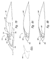
- FIG. 2 is a partially schematic cross-sectional view of the first airfoil shown in FIG. 1 with the first leading edge device in a retracted position.
- FIG. 3 is a partially schematic cross-sectional view of the first airfoil shown in FIG. 2 with the first leading edge device in a first extended position.
- FIG. 4 is a partially schematic cross-sectional view of the first airfoil shown in FIG. 2 with the leading edge device in a second extended position.
- FIG. 5A is a partially schematic cross-sectional view of the first airfoil shown in FIG. 2 with the first leading edge device in a third extended position.
- FIG. 5B is a partially schematic cross-sectional view of the first airfoil shown in FIG. 2 with the first leading edge device in a fourth extended position.
- FIG. 6 is a partially schematic isometric view of the first airfoil shown in FIGS. 1 and 2 with the first leading edge device in the second extended position.
- FIG. 7A is a partially schematic cross-sectional view of an airfoil and a leading edge device in a retracted position in accordance with another embodiment of the invention.
- FIG. 7B is a partially schematic cross-sectional view of the airfoil and leading edge device shown in FIG. 7A with a leading edge device in a first extended position.
- FIG. 7C is a partially schematic cross-sectional view of the airfoil and leading edge device shown in FIG. 7A with a leading edge device in a second extended position.
- FIG. 7D is a partially schematic cross-sectional view of the airfoil and leading edge device shown in FIG. 7A with a leading edge device in a third extended position.
- FIG. 8A is a partially schematic cross-sectional view of an airfoil where a portion of a leading edge device has been removed, and a first flow body and a second flow body have been coupled to the leading edge of the airfoil in accordance with embodiments of the invention.
- FIG. 8B is a partially schematic cross-sectional view of an airfoil where a first portion of the leading edge of the airfoil has been removed, and a second portion of the leading edge of the airfoil and a first flow body have been coupled to the airfoil in accordance with embodiments of the invention.
- FIG. 1 is a partially schematic illustration of an aerospace vehicle system 100 that includes an aerospace vehicle 108 , at least one airfoil 102 , and at least one leading edge device 110 or leading edge means.
- the aerospace vehicle 108 includes an aircraft.
- the aerospace vehicle can include other types of aerospace vehicles, for example, a space plane.
- five airfoils 110 are shown as a first airfoil 102 a , a second airfoil 102 b , a third airfoil 102 c , a fourth airfoil 102 d , and a fifth airfoil 102 e , each coupled to the aerospace vehicle 108 .
- a first leading edge device 110 a is coupled to the first airfoil 102 a (e.g., a first wing).
- a second leading edge device 110 b is coupled to a second airfoil 102 b (e.g., a second wing).
- the leading edge devices 110 can be configured to have at least two flow bodies (e.g., bodies, surfaces, objects, or structures, a portion of which is configured to interact with a fluid flow when exposed to a fluid flow).
- the at least two flow bodies can be configured to have at least one gap that provides a desired flow characteristic proximate to the leading edge devices 110 and the airfoils 102 when the leading edge devices 110 are in one or more selected stationary positions.
- FIG. 2 is a partially schematic cross-sectional view of the first airfoil 102 a and the first leading edge device 110 a taken along line 2 — 2 in FIG. 1 .
- the first leading edge device 110 a includes a first flow body 120 and a second flow body 130 .
- the first flow body 120 can be fixedly coupled to the first airfoil 102 a to form at least one first gap 114 between at least one portion 121 of the first flow body 120 and at least one portion 105 of a leading edge 104 of the first airfoil 102 a . Only one first gap 114 is shown in FIG. 2 .
- the first leading edge device 110 a can include additional first gaps and/or additional gaps between different combinations of components.
- the first leading edge device 110 a can have three flow bodies, including two flow bodies fixedly attached to the leading edge 104 of the first airfoil 102 a which form two gaps, as discussed below with reference to FIG. 7A .
- the second flow body 130 can be movably coupled to the first airfoil 102 a and can have a stationary retracted position and one or more stationary extended positions. In the retracted position (shown in FIG. 2 ), the second flow body 130 can be positioned to at least approximately aerodynamically seal the first gap 114 . For example, in the retracted position, one or more portion(s) of the second flow body 130 can be located proximate to (e.g., touching or near) the first airfoil 102 a to generally prevent a significant amount of fluid flow F, created by the motion of the vehicle through the air or fluid mass, from passing through the first gap 114 .
- the fluid flow F created by the motion of the aerospace vehicle through the air mass generally flows around (e.g., above and below) the first leading edge device 110 a .
- the second flow body 130 includes an upper trailing edge 134 a , a lower trailing edge 134 b , and a recess 136 .
- the second flow body 130 can be positioned so that the first flow body 120 is located in the recess 136 , and the upper trailing edge 134 a and the lower trailing edge 134 b can be located proximate to the first airfoil 102 a to aid in preventing fluid flow F through the first gap 114 (e.g., to form an aerodynamic seal between the second flow body 130 and the first leading edge 102 a ).
- Sealing devices 118 can be used to aid the second flow body 130 in aerodynamically sealing the first gap 114 .
- a first sealing device 118 a can be located between the upper trailing edge 134 a of the second flow body 130 to aid in aerodynamically sealing the first gap 114 when the second flow body 130 is in the retracted position.
- the sealing device 118 a includes a bulb seal attached to the upper trailing edge 134 a of the second flow body 130 that is positioned to contact the leading edge 104 of the first airfoil 102 a when the second flow body 130 is placed in the retracted position.
- a second sealing device 118 b can be located between the lower trailing edge 134 b of the second flow body 130 and the first airfoil 102 a to further aid in aerodynamically sealing the first gap 114 .
- the first leading edge device 110 a can include other sealing device arrangements or no sealing devices 118 .
- the second flow body 130 can have more or fewer trailing edges and/or the more or fewer sealing devices 118 can be used.
- the sealing devices 118 can be placed on other portions of the second flow body 130 (e.g., forward of the trailing edge(s) of the second flow body 130 ) and/or on the leading edge 104 of the first airfoil 102 a .
- the sealing device(s) 118 can include sealing device(s) different than the bulb seals shown in FIG. 2 (e.g., a flexible lip).
- FIG. 3 is a partially schematic illustration of the first airfoil 102 a , shown in FIG. 2 with the first leading edge device 110 a in a first extended position.
- the second flow body 130 In the first extended position, the second flow body 130 is positioned to allow a portion of the fluid flow F proximate to the first leading edge device 110 a and the first airfoil 102 a to flow through the first gap 114 .
- the second flow body 130 can move forward and/or down to uncover at least a potion of the first gap 114 .
- the first gap 114 can be configured to provide certain flow characteristics and can have multiple portions.
- the first gap 114 includes two portions.
- the first portion of the first gap 114 has a first distance D 1 between a first portion 121 a of the first flow body 120 and a first portion 105 a of the leading edge 104 of the first airfoil 102 a .
- the second portion of the first gap 114 has a second distance D 2 between a second portion 121 b of the first flow body 120 and a second portion 105 b of the leading edge 104 of the first airfoil 102 a .
- the first distance D 1 can be different (e.g., smaller) than the second distance D 2 , creating a tapered gap or a tapering effect.
- This tapered effect can influence the fluid flow F through the first gap 114 (e.g., by creating a venturi effect).
- the first gap 114 can include a taper in the opposite direction (e.g., where the second distance D 2 is smaller than the first distance D 1 ).
- the first gap 114 can include multiple tapered sections and/or other shapes.
- the first gap 114 can be untapered.
- the second flow body 130 is positioned to form a passageway 115 , having a third distance D 3 , between the upper trailing edge 134 a of the second flow body 130 and the leading edge 104 of the first airfoil 102 .
- Fluid flow F passing through the first gap 114 also passes through the passageway 115 . Accordingly, in certain cases, the fluid flow F through and proximate to the first gap 114 can be affected. For example, if the third distance D 3 is small, flow through the first gap 114 can be restricted and/or the direction of the fluid flow F exiting the first gap 114 can be affected (e.g., changed). If the third distance D 3 is large (larger than shown in FIG.
- the flow through the first gap 114 may be generally unrestricted and the direction of the flow can be influenced by only a small amount.
- a passageway controlling airflow through the gap can be formed by the lower trailing edge 134 b of the second flow body 130 and the leading edge 104 of the first airfoil 102 a in addition to or in lieu of the passageway 115 shown in FIG. 3 .
- FIG. 4 is a partially schematic illustration of the first airfoil 102 a , shown in FIG. 2 with the first leading edge device 110 a in a second extended position, in accordance with a further embodiment of the invention.
- the second flow body 130 can be positioned to allow fluid flow F through the first gap 114 and to form a second gap 116 with a fourth distance D 4 between the first flow body 120 and the second flow body 130 . Accordingly, a portion of the fluid flow F can flow through the first and second gaps 114 , 116 .
- the size of the second gap 116 can affect the amount of fluid flow F that passes through the second gap 116 , and thereby affect the fluid flow F proximate to the first leading edge device 110 a and the first airfoil 102 a .
- FIG. 5A shows the first airfoil 102 a with the first leading edge device 110 a in a third extended position.
- the second flow body 130 can be positioned to allow fluid flow F through the first gap 114 and to form the second gap 116 between the second flow body 130 and the first flow body 120 with a fifth distance D 5 .
- the fifth distance D 5 can be different (e.g., larger) than the fourth distance D 4 , shown in FIG. 4 .
- the first leading edge device 110 a when the first leading edge device 110 a is in the third extended position, it can create different flow characteristics proximate to the first leading edge device 11 a and/or the first airfoil 102 a than when it is in the second extended position. For example, during certain operating conditions, more fluid flow F can pass through the second gap 116 when the second flow body 130 is in the third extended position than when the second flow body 130 is in the second extended position.
- the second flow body 130 can also have one or more additional positions that affect the fluid flow F through the first gap 114 .
- FIG. 5B shows the first airfoil 102 a with the first leading edge device 110 a in a fourth extended position where the second flow body 130 is positioned to create the passageway 115 with a sixth distance D 6 between the second flow body 130 and the first airfoil 102 a .
- the sixth distance D 6 is different (e.g., smaller) than the third distance D 3 , shown in FIG. 3 .
- first leading edge device 110 a when the first leading edge device 110 a is in the fourth extended position, it can create different flow characteristics proximate to the first leading edge device 110 a and/or the first airfoil 102 a than when it is in the first extended position. For example, during certain operating conditions, fluid flow F through the first gap 114 can be more restricted when the first leading edge device 110 a is in the fourth extended position (shown in FIG. 5B ) than when the first leading edge device 110 a is in the first extended position (shown in FIG. 3 ).
- the second flow body 130 and/or the first airfoil 102 a can be used to create passageways proximate to the first gap 114 .
- the second flow body 130 can be positioned to create a passageway between a lower portion of the second flow body 130 (e.g., the lower trailing edge 134 b of the second flow body 130 ) and the first airfoil 102 a .
- the second flow body 130 can form multiple passageways between the second flow body 130 and the first airfoil 102 a (e.g., above and below the first gap 114 ).
- FIG. 6 is a partially schematic isometric view of a portion of the first airfoil 102 a shown in FIG. 1 with the first leading edge device 110 a in the second extended position.
- the first leading edge device 110 a can be coupled to the leading edge 104 of the first airfoil 102 a via supports 112 (shown as first, second, and third supports 112 a – 112 c , respectively) and tracks 111 (shown schematically in FIG. 6 ).
- the supports 112 divide multiple first gaps 114 , which are laterally disposed along the span of the leading edge 104 of the first airfoil 102 a .
- the supports 112 can fixedly couple the first flow body 120 to the first airfoil 102 a .
- the supports 112 can also carry the tracks 111 that support the second flow body 130 and allow the second flow body 130 to move (e.g., move between the retracted and at least one extended position). Additionally, the supports 112 can carry linkage(s) 144 (shown schematically in FIG. 6 ) used to move the second flow body 130 .
- the first support 112 a carries a first track 111 a and first linkage 144 a .
- the third support 112 c carries a second track 111 b and a second linkage 144 b.
- An actuation device 140 or actuation means can be used to provide the force to move the second flow body 130 .
- the actuation device 140 is coupled to a torque tube 142 which is coupled to the linkages 144 .
- the first leading edge device 110 a and the first airfoil 102 a can have other arrangements.
- multiple actuation devices 140 can be coupled to the first leading edge device 110 a and/or to the second flow body 130 with different and/or fewer tracks 111 and linkages 144 .
- the first flow body 120 is not fixedly coupled to the first airfoil 102 a .
- the first flow body 120 is coupled to the first airfoil 102 a and at least one actuation device, and is configured to be movable (e.g., movable relative to the first airfoil 102 a and/or the second flow body 130 ).
- the actuation device(s) 140 can include pneumatic, hydraulic, electric, and/or mechanical actuator(s).
- the leading edge device can include more than two flow bodies.
- FIG. 7A is a partially schematic cross-sectional view of an airfoil 702 and a leading edge device 710 (or leading edge means) having a first flow body 720 , a second flow body 730 , and a third flow body 760 in accordance with another embodiment of the invention.
- the first flow body 720 can be fixedly coupled to the airfoil 702 so that there is a first gap 714 between a portion of the first flow body 720 and a leading edge 704 of the airfoil 702 .
- the third flow body 760 can also be fixedly coupled to the airfoil 702 so that there is a second gap 716 between a portion of the first flow body 720 and a portion of the third flow body 760 .
- the third flow body 760 can be fixedly coupled to the airfoil 702 so that the third flow body 760 is positioned between the first flow body 720 and the second flow body 730 .
- the second flow body 730 In the retracted position (shown in FIG. 7A ) the second flow body 730 is positioned to at least approximately aerodynamically seal the first and second gaps 714 , 716 .
- FIG. 7B is a partially schematic illustration of the airfoil 702 , shown in FIG. 7A , with the leading edge device 710 in a first extended position.
- the second flow body 730 can be located to allow fluid flow F through the first and second gaps 714 , 716 , and thereby can affect fluid flow F proximate to the leading edge device 710 and/or the airfoil 702 .
- the leading edge device 710 can move to a second extended position, shown in FIG. 7C , where the second flow body 730 can be positioned to allow fluid flow F through the first and second gaps 714 , 716 and to form a third gap 717 between the second flow body 730 and the third flow body 760 .
- fluid flow F through the third gap 717 can affect the fluid flow proximate to the leading edge device 710 and/or the airfoil 702 .
- the leading edge device 710 can have other extended positions that can affect fluid flow F proximate to the leading edge device 710 and the airfoil 702 .
- the leading edge device 710 can move to a third extended position where the second flow body 730 allows fluid flow F through the first gap 714 , but not through the second gap 716 .
- the leading edge device 710 can include one or more extended positions where the second flow body 730 is positioned to form at least one passageway between the second flow body 730 and the airfoil 702 to affect the fluid flow F through the first and/or second gaps 714 , 716 (similar to passageways discussed above with reference to FIGS. 3 and 5B ).
- the second flow body 730 can be positioned to allow fluid flow F through the first and second gaps 714 , 716 and to form a third gap 717 between the second flow body 730 and the airfoil 702 that is larger than the third gap 717 shown in FIG. 7C .
- first and/or third flow bodies 720 , 760 are not fixedly coupled to the airfoil 702 . Instead, the first and/or third flow bodies 720 , 760 can be coupled to the airfoil 702 and at least one actuation device 740 (shown schematically).
- the first and/or second flow bodies 720 , 760 can be configured to be movable relative to the airfoil 702 , the second flow body 730 , and/or each other. Accordingly, the first and/or third flow bodies 720 , 760 can be positioned to interact with the fluid flow F (e.g., affect fluid flow F through the first, second, and/or third gaps 714 , 716 , 717 ).
- the first and/or third flow bodies can be positioned to facilitate being fully enclosed by the second flow body 730 and the leading edge of the airfoil 702 across a spanwise portion of the airfoil 702 .
- the second flow body 730 in the retracted position, can be at least approximately aerodynamically sealed with the airfoil 702 above and below the first and third flow bodies 720 , 760 across a spanwise section of the airfoil (e.g., the two trailing edges of the second flow body 730 can be approximately aerodynamically sealed with the leading edge of the airfoil 702 across the spanwise section as shown in FIG. 7A ).
- first leading edge device 850 can be removed from an airfoil 802 that is coupled to an aerospace vehicle.
- a first flow body 820 and a second flow body 830 can be coupled to the airfoil 802 to form a second leading edge device 810 configured to operate in accordance with various embodiments discussed above.
- the second flow body 830 can be coupled to one or more existing actuation devices.
- one or more separate and/or different actuation devices can be coupled between the airfoil 802 and the second leading edge device 810 .
- the combination of the airfoil 802 and the second leading edge device 810 can have the same profile as the combination of the airfoil 802 and first leading edge device did before the portion of the first leading edge device 850 was removed.
- the existing aerospace vehicle can have a leading edge device and an airfoil 802 with a first leading edge portion 804 (shown by ghosted lines).
- the existing or first leading edge device can include a portion of the first leading edge device 850 that is movable between at least two positions (e.g., a retracted and an extended position).
- the first leading edge portion 804 can be removed from the airfoil 802 .
- a second leading edge portion 860 and a first flow body 820 can be coupled to the airfoil 802 , and configured to operate with the portion of the first leading edge device 850 in accordance with various embodiments discussed above (e.g., where the portion of the first leading edge device 850 becomes or operates as a second flow body).
- the portion of the first leading edge device 850 can also be removed and replaced by a different flow body (e.g., a new second flow body).
- a different flow body e.g., a new second flow body.
- the outline of the side profile of the airfoil 802 , the second leading edge portion 860 , and the first flow body 820 can be similar in area to that of the outline of the side profile of the airfoil 802 and the first leading edge portion 804 .
- a feature of various embodiments discussed above is that a leading edge device having at least one fixed flow body and a movable flow body can be used to tailor the air flow characteristics proximate to the leading edge device and the airfoil.
- the leading edge device can have a retracted position and any combination of extended positions, including any single extended position or combination of the extended positions discussed above with reference to FIGS. 1–7D .
- at least one of the flow bodies can be positioned forward of and/or below the airfoil to form an extension of a leading edge of the airfoil.
- the leading edge device can be positioned to create various cambers and/or plan forms of the aerospace vehicle system (e.g., a leading edge device and airfoil combination) to affect the air flow characteristics proximate to the aerospace vehicle system.
- leading edge devices can be movable to selected positions where at least one gap can provide additional air flow tailoring during selected operating conditions.
- a gap can provide high energy air from the lower surface of the airfoil and leading edge device to a portion of the upper surface of the airfoil and/or leading edge device to delay boundary layer separation and/or to provide other fluid flow characteristics.
- this feature can increase the maximum lift coefficient and/or increase the stall angle of attack over that provided by current systems. Additionally, this feature can be used to improve other performance characteristics (e.g., to improve and/or control a lift over drag ratio, to control spanwise lift distribution, and/or to improve stall characteristics) over those obtained by current systems.
- leading edge devices in accordance with some or all of the embodiments described above can be used to configure aerospace vehicles for various phases of flight by moving the leading edge devices to selected positions.
- a retracted position (including the retracted position shown in FIG. 2 ) can be used during a cruise phase of flight.
- a first extended position (including the position shown in FIG. 3 ) can be used to provide a lift-to-drag coefficient that is desirable for takeoff by allowing fluid flow through a single gap.
- a second extended position with two gaps can be used during landing where a higher stall angle of attack and/or lift coefficient is desirable to reduce the vehicle's approach speed and where higher drag values can be acceptable or desired.
- An advantage of this feature is that aircraft performance can be improved over that available with current systems. For example, improvements in the lift to drag coefficient during takeoff performance can allow more weight to be carried off a given runway and lower approach speeds can allow more weight to be carried into a given runway. Additionally, improvement in other flight characteristics can increase safety (e.g., by improving stall characteristics) and/or reduce structural requirements (e.g., by controlling spanwise lift distribution). Additionally, in embodiments where flow bodies are movable (e.g., the first and second flow bodies are both movable), aircraft performance can be further tailored by affecting the fluid flow through the gaps created by the flow bodies and/or by providing a retracted position that is compact and better optimized for cruise operations.
- aerodynamic characteristics can be tailored by locating one or more slots or gaps at or near desired locations without the complexity and/or large number of moving parts of current systems. This can reduce the total number of parts required to build the leading edge device over that required with current systems.
- An advantage of this feature is that manufacturing costs can be reduced.
- Another advantage of this feature is that weight of the vehicle can be reduced, resulting in a reduction in operating costs.
- Still another advantage of this feature is that it can have fewer parts that wear out, thereby reducing maintenance costs.
Abstract
Description
Claims (25)
Priority Applications (5)
| Application Number | Priority Date | Filing Date | Title |
|---|---|---|---|
| US11/048,320 US7322547B2 (en) | 2005-01-31 | 2005-01-31 | Aerospace vehicle leading edge slat devices and corresponding methods |
| PCT/US2006/001602 WO2006083547A1 (en) | 2005-01-31 | 2006-01-17 | Aerospace vehicle leading edge slat devices and corresponding methods |
| AT06733722T ATE448140T1 (en) | 2005-01-31 | 2006-01-17 | WING FOLDING DEVICES FOR AN AIRCRAFT AND METHODS THEREOF |
| EP06733722.0A EP1843942B2 (en) | 2005-01-31 | 2006-01-17 | Aerospace vehicle leading edge slat devices and corresponding methods |
| DE602006010322T DE602006010322D1 (en) | 2005-01-31 | 2006-01-17 | PADLOCKING DEVICE FOR AN AIRCRAFT AND CORRESPONDING METHOD |
Applications Claiming Priority (1)
| Application Number | Priority Date | Filing Date | Title |
|---|---|---|---|
| US11/048,320 US7322547B2 (en) | 2005-01-31 | 2005-01-31 | Aerospace vehicle leading edge slat devices and corresponding methods |
Publications (2)
| Publication Number | Publication Date |
|---|---|
| US20060169847A1 US20060169847A1 (en) | 2006-08-03 |
| US7322547B2 true US7322547B2 (en) | 2008-01-29 |
Family
ID=36525236
Family Applications (1)
| Application Number | Title | Priority Date | Filing Date |
|---|---|---|---|
| US11/048,320 Active 2025-05-15 US7322547B2 (en) | 2005-01-31 | 2005-01-31 | Aerospace vehicle leading edge slat devices and corresponding methods |
Country Status (5)
| Country | Link |
|---|---|
| US (1) | US7322547B2 (en) |
| EP (1) | EP1843942B2 (en) |
| AT (1) | ATE448140T1 (en) |
| DE (1) | DE602006010322D1 (en) |
| WO (1) | WO2006083547A1 (en) |
Cited By (20)
| Publication number | Priority date | Publication date | Assignee | Title |
|---|---|---|---|---|
| US20070045477A1 (en) * | 2005-08-25 | 2007-03-01 | Armstrong David J | Aircraft wing slat |
| US20070241236A1 (en) * | 2004-05-10 | 2007-10-18 | Airbus Uk Limited | High-Lift Device for an Aircraft |
| US20090206209A1 (en) * | 2004-09-08 | 2009-08-20 | The Boeing Company | Systems and methods for providing differential motion to wing high lift device |
| US20100084508A1 (en) * | 2007-05-25 | 2010-04-08 | Mitsubishi Heavy Industries,Ltd. | High-lift device, wing, and noise reduction structure for high-lift device |
| US20100133387A1 (en) * | 2008-12-01 | 2010-06-03 | Wood Jeffrey H | Shape changing airfoil system |
| US7744040B2 (en) | 2005-11-21 | 2010-06-29 | The Boeing Company | Aircraft trailing edge devices, including devices with non-parallel motion paths, and associated methods |
| US20100200689A1 (en) * | 2009-02-10 | 2010-08-12 | Robert Erik Grip | Aircraft with a pressurized vessel |
| US20100224734A1 (en) * | 2009-03-05 | 2010-09-09 | Robert Erik Grip | Mechanism for changing the shape of a control surface |
| US7913955B2 (en) | 2003-11-24 | 2011-03-29 | The Boeing Company | Aircraft control surface drive system and associated methods |
| US8038103B2 (en) | 2005-11-21 | 2011-10-18 | The Boeing Company | Aircraft trailing edge devices, including devices having forwardly positioned hinge lines, and associated methods |
| US8382045B2 (en) | 2009-07-21 | 2013-02-26 | The Boeing Company | Shape-changing control surface |
| US8622350B1 (en) * | 2011-11-14 | 2014-01-07 | The Boeing Company | Compound leading edge device for aircraft |
| US8650811B2 (en) | 2011-02-04 | 2014-02-18 | The Boeing Company | Solar collector frame |
| US20150088340A1 (en) * | 2013-09-24 | 2015-03-26 | The Boeing Company | Optimized flap positioning for go-around operations |
| US20160059952A1 (en) * | 2014-08-26 | 2016-03-03 | The Boeing Company | Torque tube door |
| US9688384B1 (en) * | 2012-09-20 | 2017-06-27 | The Boeing Company | Methods and apparatus to control a gap between movable aircraft wing components |
| US10501166B2 (en) | 2012-09-20 | 2019-12-10 | The Boeing Company | Methods and apparatus to control a gap between movable aircraft wing components |
| US11235854B2 (en) * | 2019-04-01 | 2022-02-01 | Yaborä Indústria Aeronáutica S.A. | Shutter door mechanism for wing leading edge slat cut-outs |
| US11242130B2 (en) * | 2019-03-26 | 2022-02-08 | Yaborä Indústria Aeronáutica S.A. | Shuttering mechanism for wing slat telescopic tube duct |
| WO2022260894A1 (en) * | 2021-06-11 | 2022-12-15 | Patey Michael J | Aircraft wing assemblies |
Families Citing this family (10)
| Publication number | Priority date | Publication date | Assignee | Title |
|---|---|---|---|---|
| US7338018B2 (en) | 2005-02-04 | 2008-03-04 | The Boeing Company | Systems and methods for controlling aircraft flaps and spoilers |
| US7721999B2 (en) | 2005-05-20 | 2010-05-25 | The Boeing Company | Aerospace vehicle fairing systems and associated methods |
| GB2429441B (en) * | 2005-08-25 | 2011-02-23 | Gkn Aerospace Transparency Systems | Aircraft wing slat |
| DE102006053259A1 (en) * | 2006-11-11 | 2008-05-21 | Airbus Deutschland Gmbh | High-lift system on the wing of an aircraft and method for its operation |
| US8534610B1 (en) * | 2009-07-17 | 2013-09-17 | The Boeing Company | Method and apparatus for a leading edge slat on a wing of an aircraft |
| GB201018176D0 (en) * | 2010-10-28 | 2010-12-08 | Airbus Operations Ltd | Krueger |
| EP3339163A1 (en) * | 2016-12-22 | 2018-06-27 | Airbus Operations GmbH | Wing for an aircraft |
| US10766544B2 (en) * | 2017-12-29 | 2020-09-08 | ESS 2 Tech, LLC | Airfoils and machines incorporating airfoils |
| US10751583B1 (en) | 2019-04-16 | 2020-08-25 | ESS 2 Tech, LLC | Golf club head with airfoil |
| DE102022123020B3 (en) | 2022-09-09 | 2024-01-04 | Paul-Matthias Schlecht | Wing arrangement comprising a main wing and a slat attached to it in front of the main wing in the opposite direction of flow |
Citations (109)
| Publication number | Priority date | Publication date | Assignee | Title |
|---|---|---|---|---|
| US1724456A (en) * | 1928-04-24 | 1929-08-13 | Louis H Crook | Aerodynamic control of airplane wings |
| US1770575A (en) | 1927-12-03 | 1930-07-15 | Ksoll Joseph | Aeroplane with supporting surface subdivided by gaps |
| US1913169A (en) * | 1931-03-27 | 1933-06-06 | Emil F Martin | Wing and like member for aircraft |
| US2086085A (en) | 1935-05-14 | 1937-07-06 | Handley Page Ltd | Aircraft control gear |
| US2169416A (en) | 1936-06-12 | 1939-08-15 | United Aircraft Corp | Slotted deflector flap |
| US2282516A (en) | 1938-07-11 | 1942-05-12 | Messerschmitt Boelkow Blohm | Airplane wing structure |
| US2289704A (en) | 1940-02-26 | 1942-07-14 | Charles H Grant | Aircraft wing |
| US2319383A (en) | 1942-01-19 | 1943-05-18 | Edward F Zap | Linkage mounting for aerodynamic members |
| US2347230A (en) | 1938-12-16 | 1944-04-25 | Daniel R Zuck | Airplane with nonstalling and glide angle control characteristics |
| US2358985A (en) | 1940-02-23 | 1944-09-26 | James P Mcandrew | Aircraft |
| US2378528A (en) | 1939-05-17 | 1945-06-19 | Arsandaux Louis | Supporting element for aircraft |
| US2383102A (en) | 1942-02-13 | 1945-08-21 | Edward F Zap | Aerodynamic member |
| US2385351A (en) | 1942-06-23 | 1945-09-25 | Jess S W Davidsen | Control system for hydraulically actuated devices |
| US2387492A (en) | 1943-03-22 | 1945-10-23 | Curtiss Wright Corp | Hydraulically operated split flap |
| US2389274A (en) | 1941-02-04 | 1945-11-20 | Lockheed Aircraft Corp | Aircraft control system |
| US2406475A (en) | 1944-02-19 | 1946-08-27 | Samuel H Pearis | Slotted airplane wing |
| US2422296A (en) | 1941-08-22 | 1947-06-17 | Curtiss Wright Corp | Slat and flap control system |
| US2444293A (en) | 1943-06-18 | 1948-06-29 | Curtiss Wright Corp | Gap seal for flaps |
| US2458900A (en) | 1942-08-10 | 1949-01-11 | Curtiss Wright Corp | Flap operating means |
| US2504684A (en) | 1946-01-30 | 1950-04-18 | Goodrich Co B F | Extensible structure for varying the configuration of an aircraft surface |
| US2518854A (en) | 1943-06-14 | 1950-08-15 | Douglas Aircraft Co Inc | Wing high lift flap device |
| US2563453A (en) | 1951-08-07 | Device fob controlling the trailing | ||
| US2652812A (en) | 1952-05-13 | 1953-09-22 | Gen Electric | Combined manual and automatic hydraulic servomotor apparatus |
| US2665084A (en) | 1949-11-14 | 1954-01-05 | Northrop Aircraft Inc | Flap actuator and control system |
| US2851229A (en) | 1956-05-03 | 1958-09-09 | Chance Vought Aircraft Inc | Variable-contour airfoil |
| US2864239A (en) | 1956-10-04 | 1958-12-16 | Sperry Rand Corp | Electro-hydraulic servo system for steering dirigible craft |
| US2877968A (en) | 1954-10-28 | 1959-03-17 | Gen Electric | Combined manual and automatic servomotor apparatus |
| US2886008A (en) | 1953-08-03 | 1959-05-12 | Gen Motors Corp | Locking actuator and valve mechanism therefor |
| US2891740A (en) | 1957-06-27 | 1959-06-23 | John P Campbell | External-flow jet flap |
| US2892312A (en) | 1958-01-27 | 1959-06-30 | Deere & Co | Demand compensated hydraulic system |
| US2899152A (en) | 1959-08-11 | Aircraft control surface operating mechanism | ||
| US2912190A (en) | 1958-05-05 | 1959-11-10 | Chance Vought Aircraft Inc | Variable-contour airfoil |
| US2920844A (en) | 1957-04-12 | 1960-01-12 | North American Aviation Inc | Aircraft boundary-layer control system |
| US2938680A (en) * | 1957-07-02 | 1960-05-31 | North American Aviation Inc | Multiple position airfoil slat |
| US2990145A (en) | 1956-11-05 | 1961-06-27 | Gen Electric | Integrated hydraulic power actuator |
| US2990144A (en) | 1956-11-05 | 1961-06-27 | Gen Electric | Integrated hydraulic power actuator |
| US3013748A (en) | 1959-03-11 | 1961-12-19 | Douglas Aircraft Co Inc | Aircraft flap supporting and operating mechanism |
| US3089666A (en) | 1961-04-13 | 1963-05-14 | Boeing Co | Airplane having changeable thrust direction |
| US3102607A (en) | 1960-12-19 | 1963-09-03 | Charles E Roberts | Carrier system for transport and delivery along a trackway |
| US3112089A (en) | 1960-10-12 | 1963-11-26 | Dornier Werke Gmbh | Airplane wing flaps |
| US3136504A (en) | 1963-07-02 | 1964-06-09 | William F Carr | Electrical primary flight control system |
| US3203275A (en) | 1962-11-26 | 1965-08-31 | Vaino A Hoover | Mechanical actuator |
| US3203647A (en) | 1961-12-06 | 1965-08-31 | Alvarez-Calderon Alberto | High lift fdaps for aircraft wings |
| US3282535A (en) | 1964-11-12 | 1966-11-01 | Boeing Co | Leading edge spoiler and flap wing stall control means |
| US3375998A (en) | 1962-04-16 | 1968-04-02 | Alberto Alvarez Calderon | Leading edge flap and apparatus thereof |
| US3423858A (en) | 1967-01-10 | 1969-01-28 | Speno International | Automatic control system for railway work apparatus |
| US3447763A (en) | 1964-12-11 | 1969-06-03 | Power Jet Research & Dev Ltd | Flap systems for aircraft |
| US3463418A (en) | 1968-03-20 | 1969-08-26 | Edmond S Miksch | Vortex generator for airplane wing |
| US3504870A (en) | 1967-12-08 | 1970-04-07 | Boeing Co | Aircraft wing variable camber leading edge flap |
| US3528632A (en) | 1967-05-16 | 1970-09-15 | Hawker Siddeley Aviation Ltd | High lift flaps for aircraft |
| US3539133A (en) | 1968-05-20 | 1970-11-10 | Robertson Aircraft Corp | Inherently stable tapered wing flaperon airplane |
| US3556439A (en) | 1968-11-22 | 1971-01-19 | Boeing Co | Methods and high lift systems for making an aircraft wing more efficient for takeoffs and landings |
| US3587311A (en) | 1969-06-19 | 1971-06-28 | Teledyne Inc | Aircraft instrument system |
| US3589648A (en) | 1969-01-02 | 1971-06-29 | Lockheed Aircraft Corp | Means for controlling the vertical path of an aircraft |
| US3642234A (en) * | 1968-12-30 | 1972-02-15 | Dassault Avions | Aircraft |
| US3653611A (en) | 1970-03-24 | 1972-04-04 | Mason Trupp | Slotted delta wing aircraft |
| US3659810A (en) | 1968-05-20 | 1972-05-02 | James L Robertson | Inherently stable tapered wing flaperon airplane |
| US3677504A (en) | 1969-08-28 | 1972-07-18 | Ver Flugtechnische Werke | Control flap arrangement |
| US3704843A (en) | 1970-06-11 | 1972-12-05 | Mc Donnell Douglas Corp | Aircraft control system |
| US3704828A (en) | 1969-12-16 | 1972-12-05 | Hamburger Flugzeubau Gmbh | Aircraft fan with outflow deflectors |
| US3743219A (en) | 1971-06-30 | 1973-07-03 | Boeing Co | High lift leading edge device |
| US3794276A (en) | 1971-10-07 | 1974-02-26 | Lucas Aerospace Ltd | Electro-hydraulic actuating systems for aircraft control surfaces |
| US3804267A (en) | 1972-04-03 | 1974-04-16 | Sperry Rand Corp | Bale wagon |
| US3807447A (en) | 1972-02-24 | 1974-04-30 | Daikin Ind Ltd | Fluid controlling apparatus |
| US3813062A (en) | 1971-10-12 | 1974-05-28 | A Prather | Fan-like tail section for man-powered glider aircraft |
| US3827658A (en) | 1973-04-05 | 1974-08-06 | Lockheed Aircraft Corp | Actuating means for a vane |
| US3831886A (en) | 1973-01-26 | 1974-08-27 | Lockheed Aircraft Corp | Airfoil with extendible and retractable leading edge |
| US3836099A (en) | 1973-09-28 | 1974-09-17 | Us Navy | Airfoil camber change system |
| US3837601A (en) | 1973-03-09 | 1974-09-24 | Boeing Co | Aerodynamic slot closing mechanism |
| US3862730A (en) | 1973-10-23 | 1975-01-28 | United Aircraft Corp | Fas actuation system |
| US3874617A (en) | 1974-07-17 | 1975-04-01 | Mc Donnell Douglas Corp | Stol flaps |
| US3897029A (en) * | 1973-07-09 | 1975-07-29 | Alberto Alvarez Calderon | Variable camber multi-slotted flaps |
| US3904152A (en) * | 1974-03-13 | 1975-09-09 | Lockheed Aircraft Corp | Variable area, variable camber wing for aircraft |
| US3910530A (en) | 1973-11-07 | 1975-10-07 | Boeing Co | Leading edge flap |
| US3913450A (en) | 1973-05-11 | 1975-10-21 | Dreis & Krump Manufacturing Co | Hydraulic Control system for press brakes or the like |
| US3917192A (en) * | 1973-07-09 | 1975-11-04 | Alvarez Calderon Alberto | Flap mechanisms and apparatus |
| US3931374A (en) | 1969-10-13 | 1976-01-06 | Office National D'etudes Et De Recherches Aerospatiales (O.N.E.R.A.) | Processes for the manufacture of fuel blocks containing a metallic powder and in the corresponding blocks |
| US3941341A (en) | 1974-12-13 | 1976-03-02 | Brogdon Jr Glenn F | Quick-release roller attachment for supporting a rope or hose and the like on an aerial ladder |
| US3941334A (en) | 1975-03-28 | 1976-03-02 | The Boeing Company | Variable camber airfoil |
| US3949957A (en) * | 1973-11-06 | 1976-04-13 | Societe Nationale Industrielle Aerospatiale | Actuating system for wing leading-edge slats |
| US3968946A (en) | 1975-03-31 | 1976-07-13 | The Boeing Company | Extendable aerodynamic fairing |
| US3985319A (en) | 1975-02-03 | 1976-10-12 | The Boeing Company | Variable pivot trailing edge flap |
| US3987983A (en) | 1974-12-20 | 1976-10-26 | The Boeing Company | Trailing edge flaps having spanwise aerodynamic slot opening and closing mechanism |
| US3991574A (en) | 1975-02-03 | 1976-11-16 | Frazier Larry Vane W | Fluid pressure power plant with double-acting piston |
| US3992979A (en) | 1974-12-20 | 1976-11-23 | Joseph Lucas (Industries) Limited | Hydraulic actuating arrangements |
| US3993584A (en) | 1972-12-20 | 1976-11-23 | The Harshaw Chemical Company | Agglomerate containing fibrous polytetrafluoroethylene |
| US3994451A (en) | 1974-03-28 | 1976-11-30 | The Boeing Company | Variable camber airfoil |
| US4011888A (en) | 1976-03-12 | 1977-03-15 | Elevator Equipment Co. | Unitary elevator up level control valve |
| US4015787A (en) | 1975-11-17 | 1977-04-05 | Fairchild Industries Inc. | Aircraft wing |
| US4106730A (en) | 1976-10-01 | 1978-08-15 | The Boeing Company | Engine out control system for STOL aircraft |
| US4117996A (en) | 1975-06-23 | 1978-10-03 | Sherman Irving R | Variable aerodynamic compression flaps |
| US4120470A (en) | 1976-09-28 | 1978-10-17 | The Boeing Company | Efficient trailing edge system for an aircraft wing |
| US4131253A (en) | 1977-07-21 | 1978-12-26 | The Boeing Company | Variable camber trailing edge for airfoil |
| US4146200A (en) | 1977-09-14 | 1979-03-27 | Northrop Corporation | Auxiliary flaperon control for aircraft |
| US4171787A (en) | 1977-07-21 | 1979-10-23 | Zapel Edwin J | Variable camber leading edge for airfoil |
| US4180222A (en) | 1976-12-27 | 1979-12-25 | Lockheed Aircraft Corporation | Aileron segment control for a flaperon system |
| US4181275A (en) | 1977-06-07 | 1980-01-01 | Messerschmitt-Bolkow-Blohm Gmbh | Apparatus for operating flap means secured to the wing of an aircraft |
| US4189122A (en) | 1978-07-21 | 1980-02-19 | The United States Of America As Represented By The Secretary Of The Navy | Wide angle gimbal system |
| US4189121A (en) | 1978-01-23 | 1980-02-19 | Boeing Commercial Airplane Company | Variable twist leading edge flap |
| US4189120A (en) | 1977-12-14 | 1980-02-19 | Boeing Commercial Airplane Company | Variable camber leading edge flap |
| US4200253A (en) | 1977-04-06 | 1980-04-29 | British Aerospace | Aircraft wing drooping leading edge device |
| US4202519A (en) | 1978-09-08 | 1980-05-13 | The Boeing Company | Airfoil leading edge slat apparatus |
| US4240255A (en) | 1978-06-01 | 1980-12-23 | Les Applications Hydrauliques R. Sarrazin S.A. | Integrated control device for a fluid circuit and applications thereof |
| US4262868A (en) | 1979-05-29 | 1981-04-21 | The Boeing Company | Three-position variable camber flap |
| US4275942A (en) | 1978-12-26 | 1981-06-30 | The Boeing Company | Stowage bin mechanism |
| US4283029A (en) | 1979-01-02 | 1981-08-11 | Rudolph Peter K C | Actuating apparatus for a flap system having an upper surface blowing powered lift system |
| US4285482A (en) | 1979-08-10 | 1981-08-25 | The Boeing Company | Wing leading edge high lift device |
| US4360176A (en) * | 1979-11-05 | 1982-11-23 | The Boeing Company | Wing leading edge slat |
| US4838503A (en) * | 1987-05-13 | 1989-06-13 | British Aerospace Plc | Mechanism for supporting and extending a high lift device for aircraft wings |
Family Cites Families (75)
| Publication number | Priority date | Publication date | Assignee | Title |
|---|---|---|---|---|
| DE387833C (en) * | 1921-05-27 | 1924-01-04 | Handley Page Ltd | Wing for aircraft |
| FR705155A (en) * | 1930-11-05 | 1931-06-02 | Improvements to air navigation devices | |
| FR978969A (en) * | 1942-12-29 | 1951-04-20 | Development of high-lift slit wing planes | |
| FR984443A (en) * | 1943-09-24 | 1951-07-05 | High lift wing | |
| FR61015E (en) * | 1946-12-03 | 1955-03-23 | ||
| DE1129379B (en) * | 1960-11-11 | 1962-05-10 | Dornier Werke Gmbh | Airplane wing with fixed leading wing |
| GB1181991A (en) * | 1967-04-14 | 1970-02-18 | Edward M Lanier | Aircraft Lift-Increasing Device |
| US3711039A (en) * | 1970-10-26 | 1973-01-16 | Boeing Co | Pneumatic leading edge flap for an aircraft wing |
| US3949956A (en) † | 1973-07-09 | 1976-04-13 | Alvarez Calderon Alberto | Parametrically shaped leading edge flaps |
| US4312486A (en) * | 1979-09-20 | 1982-01-26 | The Boeing Company | Variable camber trailing edge for airfoil |
| US4368937A (en) * | 1981-02-17 | 1983-01-18 | The Boeing Company | Overhead stowage bin mechanism |
| US4498646A (en) * | 1981-07-01 | 1985-02-12 | Dornier Gmbh | Wing for short take-off and landing aircraft |
| US4427168A (en) * | 1981-09-29 | 1984-01-24 | The Boeing Company | Variable camber leading edge mechanism with Krueger flap |
| US4444368A (en) * | 1981-10-30 | 1984-04-24 | The United States Of America As Represented By The Administrator Of The National Aeronautics And Space Administration | Slotted variable camber flap |
| US4441675A (en) * | 1982-06-25 | 1984-04-10 | Mcdonnell Douglas Corporation | High lift surface actuation system |
| DE3275176D1 (en) * | 1982-08-09 | 1987-02-26 | Boeing Co | Wing leading edge slat |
| US4575030A (en) * | 1982-09-13 | 1986-03-11 | The Boeing Company | Laminar flow control airfoil |
| US4496121A (en) * | 1982-09-21 | 1985-01-29 | The Boeing Company | Control surface lock for flutter constraint |
| US4729528A (en) * | 1983-02-28 | 1988-03-08 | Northrop Corporation | Aeroelastic control flap |
| US4544117A (en) | 1983-11-14 | 1985-10-01 | Lockheed Corporation | Leading edge flap and boundary layer control system |
| FR2555960B1 (en) * | 1983-12-06 | 1986-09-19 | Aerospatiale | BOOM AIRCRAFT WING PROVIDED WITH A HYPERSUSTENTATOR SYSTEM AND AN ENGINE SUSPENSION MAT, AS WELL AS AN ENGINE SUSPENSION MAT FOR SUCH A WING |
| US4575099A (en) * | 1984-01-27 | 1986-03-11 | General Electric Company | High excursion seal with flexible membrane to prevent gas leakage through hinge |
| US4899284A (en) * | 1984-09-27 | 1990-02-06 | The Boeing Company | Wing lift/drag optimizing system |
| US4576347A (en) * | 1984-10-30 | 1986-03-18 | The Boeing Company | Flap torque tube slot seal |
| US5082207A (en) * | 1985-02-04 | 1992-01-21 | Rockwell International Corporation | Active flexible wing aircraft control system |
| EP0218021B1 (en) * | 1985-08-29 | 1988-06-08 | Messerschmitt-Bölkow-Blohm Gesellschaft mit beschränkter Haftung | Flaps arrangement for an aircraft wing |
| DE3530865A1 (en) * | 1985-08-29 | 1987-03-12 | Messerschmitt Boelkow Blohm | DRIVE AND GUIDE DEVICE FOR A FLAP SYSTEM ARRANGED ON AN AIRCRAFT WING |
| US4796192A (en) * | 1985-11-04 | 1989-01-03 | The Boeing Company | Maneuver load alleviation system |
| US4650140A (en) * | 1985-12-30 | 1987-03-17 | The Boeing Company | Wind edge movable airfoil having variable camber |
| US4717097A (en) * | 1986-03-03 | 1988-01-05 | The Boeing Company | Aircraft wings with aileron-supported ground speed spoilers and trailing edge flaps |
| US5100082A (en) * | 1987-09-17 | 1992-03-31 | The Boeing Company | Hydraulic power supplies |
| US4823836A (en) * | 1988-05-31 | 1989-04-25 | Lothar Bachmann | Dampers with leaf spring seals |
| US5082208A (en) * | 1989-09-29 | 1992-01-21 | The Boeing Company | System and method for controlling an aircraft flight control member |
| US5094412A (en) * | 1989-10-13 | 1992-03-10 | Bell Helicopter Textron Inc. | Flaperon system for tilt rotor wings |
| US5088665A (en) * | 1989-10-31 | 1992-02-18 | The United States Of America As Represented By The Administrator Of The National Aeronautics And Space Administration | Serrated trailing edges for improving lift and drag characteristics of lifting surfaces |
| US5094411A (en) * | 1990-10-19 | 1992-03-10 | Vigyan, Inc. | Control configured vortex flaps |
| US5203619A (en) * | 1990-11-07 | 1993-04-20 | Intermetro Industries Corporation | Storage system including a vertically retractable storage unit |
| US5280863A (en) * | 1991-11-20 | 1994-01-25 | Hugh Schmittle | Lockable free wing aircraft |
| US5493497A (en) * | 1992-06-03 | 1996-02-20 | The Boeing Company | Multiaxis redundant fly-by-wire primary flight control system |
| US5282591A (en) * | 1992-12-21 | 1994-02-01 | The United States Of America As Represented By The Secretary Of The Navy | Active vortex control for a high performance wing |
| FR2709110B1 (en) * | 1993-08-20 | 1995-11-10 | Lucas Air Equipement | Servo-control device of an aircraft flight control member. |
| US5388788A (en) * | 1993-12-16 | 1995-02-14 | The Boeing Company | Hinge fairings for control surfaces |
| DE4422152C2 (en) * | 1994-06-27 | 2000-02-03 | Daimler Chrysler Aerospace | Method and arrangement for optimizing the aerodynamic effect of a wing |
| FR2728535A1 (en) * | 1994-12-26 | 1996-06-28 | Aerospatiale | VARIABLE SLOTTED AEROBRAKE FOR AIRCRAFT WING |
| US5609020A (en) * | 1995-05-15 | 1997-03-11 | The Boeing Company | Thrust reverser synchronization shaft lock |
| US5681013A (en) * | 1995-12-26 | 1997-10-28 | The Boeing Company | Vortex leading edge flap assembly for supersonic airplanes |
| US5875998A (en) * | 1996-02-05 | 1999-03-02 | Daimler-Benz Aerospace Airbus Gmbh | Method and apparatus for optimizing the aerodynamic effect of an airfoil |
| US5743490A (en) * | 1996-02-16 | 1998-04-28 | Sundstrand Corporation | Flap/slat actuation system for an aircraft |
| WO1997038900A1 (en) * | 1996-04-13 | 1997-10-23 | Michael Craig Broadbent | Variable camber wing mechanism |
| JP3638745B2 (en) * | 1997-02-07 | 2005-04-13 | 富士重工業株式会社 | Rotor blade with rotary spoiler |
| US6209824B1 (en) * | 1997-09-17 | 2001-04-03 | The Boeing Company | Control surface for an aircraft |
| US6079672A (en) * | 1997-12-18 | 2000-06-27 | Lam; Lawrence Y. | Aileron for fixed wing aircraft |
| EP0958999B2 (en) * | 1998-05-21 | 2007-08-29 | McDonnell Douglas Corporation | Aerofoil |
| US6045204A (en) * | 1998-10-13 | 2000-04-04 | Hexcel Corporation | Overhead stowage bins in aircraft |
| GB9823599D0 (en) * | 1998-10-28 | 1998-12-23 | Lucas Ind Plc | Brake assembly |
| US6189837B1 (en) * | 1998-10-29 | 2001-02-20 | The Boeing Company | Auxiliary spoiler retract system |
| DE19910551C2 (en) * | 1999-03-10 | 2001-04-05 | Eads Airbus Gmbh | Aircraft wing with at least one short-coupled engine |
| DE10019187C1 (en) * | 2000-04-17 | 2002-01-03 | Airbus Gmbh | Pressure control for a sinker |
| US6375126B1 (en) * | 2000-11-16 | 2002-04-23 | The Boeing Company | Variable camber leading edge for an airfoil |
| US20020046087A1 (en) * | 2000-12-18 | 2002-04-18 | John Hey | Method of drawing attention to advertisements |
| US6547183B2 (en) * | 2001-08-02 | 2003-04-15 | The Boeing Company | Moveable closet |
| US6870490B2 (en) * | 2001-08-23 | 2005-03-22 | Honeywell International Inc. | Display of altitude and path capture trajectories |
| GB0127254D0 (en) * | 2001-11-13 | 2002-01-02 | Lucas Industries Ltd | Aircraft flight surface control system |
| US6698523B2 (en) * | 2002-07-02 | 2004-03-02 | Husco International, Inc. | Electrohydraulic control system for implement lift cylinders |
| US7258308B2 (en) * | 2002-07-02 | 2007-08-21 | The Boeing Company | Method and apparatus for controlling airflow with a gapped trailing edge device having a flexible flow surface |
| US20040059474A1 (en) * | 2002-09-20 | 2004-03-25 | Boorman Daniel J. | Apparatuses and methods for displaying autoflight information |
| US7048235B2 (en) * | 2002-10-09 | 2006-05-23 | The Boeing Company | Slotted aircraft wing |
| US6827311B2 (en) * | 2003-04-07 | 2004-12-07 | Honeywell International, Inc. | Flight control actuation system |
| US7243881B2 (en) * | 2003-06-03 | 2007-07-17 | The Boeing Company | Multi-function trailing edge devices and associated methods |
| US6843452B1 (en) * | 2003-06-17 | 2005-01-18 | The Boeing Company | Variable trailing edge geometry and spanload control |
| US7028948B2 (en) * | 2003-08-28 | 2006-04-18 | The Boeing Company | Apparatus for increase of aircraft lift and maneuverability |
| FR2859976B1 (en) * | 2003-09-22 | 2006-12-08 | Airbus France | AIRCRAFT WING COMPRISING AT LEAST ONE DEPORTER SHUTTER AND DEPORTER SHUTTER FOR SAID WING |
| US7270305B2 (en) * | 2004-06-15 | 2007-09-18 | The Boeing Company | Aircraft leading edge apparatuses and corresponding methods |
| DE102004040313B4 (en) * | 2004-08-19 | 2008-02-21 | Airbus Deutschland Gmbh | System for adjusting the spanwise load distribution of a wing |
| US7494094B2 (en) * | 2004-09-08 | 2009-02-24 | The Boeing Company | Aircraft wing systems for providing differential motion to deployable lift devices |
-
2005
- 2005-01-31 US US11/048,320 patent/US7322547B2/en active Active
-
2006
- 2006-01-17 DE DE602006010322T patent/DE602006010322D1/en active Active
- 2006-01-17 AT AT06733722T patent/ATE448140T1/en not_active IP Right Cessation
- 2006-01-17 WO PCT/US2006/001602 patent/WO2006083547A1/en active Application Filing
- 2006-01-17 EP EP06733722.0A patent/EP1843942B2/en active Active
Patent Citations (109)
| Publication number | Priority date | Publication date | Assignee | Title |
|---|---|---|---|---|
| US2899152A (en) | 1959-08-11 | Aircraft control surface operating mechanism | ||
| US2563453A (en) | 1951-08-07 | Device fob controlling the trailing | ||
| US1770575A (en) | 1927-12-03 | 1930-07-15 | Ksoll Joseph | Aeroplane with supporting surface subdivided by gaps |
| US1724456A (en) * | 1928-04-24 | 1929-08-13 | Louis H Crook | Aerodynamic control of airplane wings |
| US1913169A (en) * | 1931-03-27 | 1933-06-06 | Emil F Martin | Wing and like member for aircraft |
| US2086085A (en) | 1935-05-14 | 1937-07-06 | Handley Page Ltd | Aircraft control gear |
| US2169416A (en) | 1936-06-12 | 1939-08-15 | United Aircraft Corp | Slotted deflector flap |
| US2282516A (en) | 1938-07-11 | 1942-05-12 | Messerschmitt Boelkow Blohm | Airplane wing structure |
| US2347230A (en) | 1938-12-16 | 1944-04-25 | Daniel R Zuck | Airplane with nonstalling and glide angle control characteristics |
| US2378528A (en) | 1939-05-17 | 1945-06-19 | Arsandaux Louis | Supporting element for aircraft |
| US2358985A (en) | 1940-02-23 | 1944-09-26 | James P Mcandrew | Aircraft |
| US2289704A (en) | 1940-02-26 | 1942-07-14 | Charles H Grant | Aircraft wing |
| US2389274A (en) | 1941-02-04 | 1945-11-20 | Lockheed Aircraft Corp | Aircraft control system |
| US2422296A (en) | 1941-08-22 | 1947-06-17 | Curtiss Wright Corp | Slat and flap control system |
| US2319383A (en) | 1942-01-19 | 1943-05-18 | Edward F Zap | Linkage mounting for aerodynamic members |
| US2383102A (en) | 1942-02-13 | 1945-08-21 | Edward F Zap | Aerodynamic member |
| US2385351A (en) | 1942-06-23 | 1945-09-25 | Jess S W Davidsen | Control system for hydraulically actuated devices |
| US2458900A (en) | 1942-08-10 | 1949-01-11 | Curtiss Wright Corp | Flap operating means |
| US2387492A (en) | 1943-03-22 | 1945-10-23 | Curtiss Wright Corp | Hydraulically operated split flap |
| US2518854A (en) | 1943-06-14 | 1950-08-15 | Douglas Aircraft Co Inc | Wing high lift flap device |
| US2444293A (en) | 1943-06-18 | 1948-06-29 | Curtiss Wright Corp | Gap seal for flaps |
| US2406475A (en) | 1944-02-19 | 1946-08-27 | Samuel H Pearis | Slotted airplane wing |
| US2504684A (en) | 1946-01-30 | 1950-04-18 | Goodrich Co B F | Extensible structure for varying the configuration of an aircraft surface |
| US2665084A (en) | 1949-11-14 | 1954-01-05 | Northrop Aircraft Inc | Flap actuator and control system |
| US2652812A (en) | 1952-05-13 | 1953-09-22 | Gen Electric | Combined manual and automatic hydraulic servomotor apparatus |
| US2886008A (en) | 1953-08-03 | 1959-05-12 | Gen Motors Corp | Locking actuator and valve mechanism therefor |
| US2877968A (en) | 1954-10-28 | 1959-03-17 | Gen Electric | Combined manual and automatic servomotor apparatus |
| US2851229A (en) | 1956-05-03 | 1958-09-09 | Chance Vought Aircraft Inc | Variable-contour airfoil |
| US2864239A (en) | 1956-10-04 | 1958-12-16 | Sperry Rand Corp | Electro-hydraulic servo system for steering dirigible craft |
| US2990145A (en) | 1956-11-05 | 1961-06-27 | Gen Electric | Integrated hydraulic power actuator |
| US2990144A (en) | 1956-11-05 | 1961-06-27 | Gen Electric | Integrated hydraulic power actuator |
| US2920844A (en) | 1957-04-12 | 1960-01-12 | North American Aviation Inc | Aircraft boundary-layer control system |
| US2891740A (en) | 1957-06-27 | 1959-06-23 | John P Campbell | External-flow jet flap |
| US2938680A (en) * | 1957-07-02 | 1960-05-31 | North American Aviation Inc | Multiple position airfoil slat |
| US2892312A (en) | 1958-01-27 | 1959-06-30 | Deere & Co | Demand compensated hydraulic system |
| US2912190A (en) | 1958-05-05 | 1959-11-10 | Chance Vought Aircraft Inc | Variable-contour airfoil |
| US3013748A (en) | 1959-03-11 | 1961-12-19 | Douglas Aircraft Co Inc | Aircraft flap supporting and operating mechanism |
| US3112089A (en) | 1960-10-12 | 1963-11-26 | Dornier Werke Gmbh | Airplane wing flaps |
| US3102607A (en) | 1960-12-19 | 1963-09-03 | Charles E Roberts | Carrier system for transport and delivery along a trackway |
| US3089666A (en) | 1961-04-13 | 1963-05-14 | Boeing Co | Airplane having changeable thrust direction |
| US3203647A (en) | 1961-12-06 | 1965-08-31 | Alvarez-Calderon Alberto | High lift fdaps for aircraft wings |
| US3375998A (en) | 1962-04-16 | 1968-04-02 | Alberto Alvarez Calderon | Leading edge flap and apparatus thereof |
| US3203275A (en) | 1962-11-26 | 1965-08-31 | Vaino A Hoover | Mechanical actuator |
| US3136504A (en) | 1963-07-02 | 1964-06-09 | William F Carr | Electrical primary flight control system |
| US3282535A (en) | 1964-11-12 | 1966-11-01 | Boeing Co | Leading edge spoiler and flap wing stall control means |
| US3447763A (en) | 1964-12-11 | 1969-06-03 | Power Jet Research & Dev Ltd | Flap systems for aircraft |
| US3423858A (en) | 1967-01-10 | 1969-01-28 | Speno International | Automatic control system for railway work apparatus |
| US3528632A (en) | 1967-05-16 | 1970-09-15 | Hawker Siddeley Aviation Ltd | High lift flaps for aircraft |
| US3504870A (en) | 1967-12-08 | 1970-04-07 | Boeing Co | Aircraft wing variable camber leading edge flap |
| US3463418A (en) | 1968-03-20 | 1969-08-26 | Edmond S Miksch | Vortex generator for airplane wing |
| US3539133A (en) | 1968-05-20 | 1970-11-10 | Robertson Aircraft Corp | Inherently stable tapered wing flaperon airplane |
| US3659810A (en) | 1968-05-20 | 1972-05-02 | James L Robertson | Inherently stable tapered wing flaperon airplane |
| US3556439A (en) | 1968-11-22 | 1971-01-19 | Boeing Co | Methods and high lift systems for making an aircraft wing more efficient for takeoffs and landings |
| US3642234A (en) * | 1968-12-30 | 1972-02-15 | Dassault Avions | Aircraft |
| US3589648A (en) | 1969-01-02 | 1971-06-29 | Lockheed Aircraft Corp | Means for controlling the vertical path of an aircraft |
| US3587311A (en) | 1969-06-19 | 1971-06-28 | Teledyne Inc | Aircraft instrument system |
| US3677504A (en) | 1969-08-28 | 1972-07-18 | Ver Flugtechnische Werke | Control flap arrangement |
| US3931374A (en) | 1969-10-13 | 1976-01-06 | Office National D'etudes Et De Recherches Aerospatiales (O.N.E.R.A.) | Processes for the manufacture of fuel blocks containing a metallic powder and in the corresponding blocks |
| US3704828A (en) | 1969-12-16 | 1972-12-05 | Hamburger Flugzeubau Gmbh | Aircraft fan with outflow deflectors |
| US3653611A (en) | 1970-03-24 | 1972-04-04 | Mason Trupp | Slotted delta wing aircraft |
| US3704843A (en) | 1970-06-11 | 1972-12-05 | Mc Donnell Douglas Corp | Aircraft control system |
| US3743219A (en) | 1971-06-30 | 1973-07-03 | Boeing Co | High lift leading edge device |
| US3794276A (en) | 1971-10-07 | 1974-02-26 | Lucas Aerospace Ltd | Electro-hydraulic actuating systems for aircraft control surfaces |
| US3813062A (en) | 1971-10-12 | 1974-05-28 | A Prather | Fan-like tail section for man-powered glider aircraft |
| US3807447A (en) | 1972-02-24 | 1974-04-30 | Daikin Ind Ltd | Fluid controlling apparatus |
| US3804267A (en) | 1972-04-03 | 1974-04-16 | Sperry Rand Corp | Bale wagon |
| US3993584A (en) | 1972-12-20 | 1976-11-23 | The Harshaw Chemical Company | Agglomerate containing fibrous polytetrafluoroethylene |
| US3831886A (en) | 1973-01-26 | 1974-08-27 | Lockheed Aircraft Corp | Airfoil with extendible and retractable leading edge |
| US3837601A (en) | 1973-03-09 | 1974-09-24 | Boeing Co | Aerodynamic slot closing mechanism |
| US3827658A (en) | 1973-04-05 | 1974-08-06 | Lockheed Aircraft Corp | Actuating means for a vane |
| US3913450A (en) | 1973-05-11 | 1975-10-21 | Dreis & Krump Manufacturing Co | Hydraulic Control system for press brakes or the like |
| US3897029A (en) * | 1973-07-09 | 1975-07-29 | Alberto Alvarez Calderon | Variable camber multi-slotted flaps |
| US3917192A (en) * | 1973-07-09 | 1975-11-04 | Alvarez Calderon Alberto | Flap mechanisms and apparatus |
| US3836099A (en) | 1973-09-28 | 1974-09-17 | Us Navy | Airfoil camber change system |
| US3862730A (en) | 1973-10-23 | 1975-01-28 | United Aircraft Corp | Fas actuation system |
| US3949957A (en) * | 1973-11-06 | 1976-04-13 | Societe Nationale Industrielle Aerospatiale | Actuating system for wing leading-edge slats |
| US3910530A (en) | 1973-11-07 | 1975-10-07 | Boeing Co | Leading edge flap |
| US3904152A (en) * | 1974-03-13 | 1975-09-09 | Lockheed Aircraft Corp | Variable area, variable camber wing for aircraft |
| US3994451A (en) | 1974-03-28 | 1976-11-30 | The Boeing Company | Variable camber airfoil |
| US3874617A (en) | 1974-07-17 | 1975-04-01 | Mc Donnell Douglas Corp | Stol flaps |
| US3941341A (en) | 1974-12-13 | 1976-03-02 | Brogdon Jr Glenn F | Quick-release roller attachment for supporting a rope or hose and the like on an aerial ladder |
| US3992979A (en) | 1974-12-20 | 1976-11-23 | Joseph Lucas (Industries) Limited | Hydraulic actuating arrangements |
| US3987983A (en) | 1974-12-20 | 1976-10-26 | The Boeing Company | Trailing edge flaps having spanwise aerodynamic slot opening and closing mechanism |
| US3985319A (en) | 1975-02-03 | 1976-10-12 | The Boeing Company | Variable pivot trailing edge flap |
| US3991574A (en) | 1975-02-03 | 1976-11-16 | Frazier Larry Vane W | Fluid pressure power plant with double-acting piston |
| US3941334A (en) | 1975-03-28 | 1976-03-02 | The Boeing Company | Variable camber airfoil |
| US3968946A (en) | 1975-03-31 | 1976-07-13 | The Boeing Company | Extendable aerodynamic fairing |
| US4117996A (en) | 1975-06-23 | 1978-10-03 | Sherman Irving R | Variable aerodynamic compression flaps |
| US4015787A (en) | 1975-11-17 | 1977-04-05 | Fairchild Industries Inc. | Aircraft wing |
| US4011888A (en) | 1976-03-12 | 1977-03-15 | Elevator Equipment Co. | Unitary elevator up level control valve |
| US4120470A (en) | 1976-09-28 | 1978-10-17 | The Boeing Company | Efficient trailing edge system for an aircraft wing |
| US4106730A (en) | 1976-10-01 | 1978-08-15 | The Boeing Company | Engine out control system for STOL aircraft |
| US4180222A (en) | 1976-12-27 | 1979-12-25 | Lockheed Aircraft Corporation | Aileron segment control for a flaperon system |
| US4200253A (en) | 1977-04-06 | 1980-04-29 | British Aerospace | Aircraft wing drooping leading edge device |
| US4181275A (en) | 1977-06-07 | 1980-01-01 | Messerschmitt-Bolkow-Blohm Gmbh | Apparatus for operating flap means secured to the wing of an aircraft |
| US4131253A (en) | 1977-07-21 | 1978-12-26 | The Boeing Company | Variable camber trailing edge for airfoil |
| US4171787A (en) | 1977-07-21 | 1979-10-23 | Zapel Edwin J | Variable camber leading edge for airfoil |
| US4146200A (en) | 1977-09-14 | 1979-03-27 | Northrop Corporation | Auxiliary flaperon control for aircraft |
| US4189120A (en) | 1977-12-14 | 1980-02-19 | Boeing Commercial Airplane Company | Variable camber leading edge flap |
| US4189121A (en) | 1978-01-23 | 1980-02-19 | Boeing Commercial Airplane Company | Variable twist leading edge flap |
| US4240255A (en) | 1978-06-01 | 1980-12-23 | Les Applications Hydrauliques R. Sarrazin S.A. | Integrated control device for a fluid circuit and applications thereof |
| US4189122A (en) | 1978-07-21 | 1980-02-19 | The United States Of America As Represented By The Secretary Of The Navy | Wide angle gimbal system |
| US4202519A (en) | 1978-09-08 | 1980-05-13 | The Boeing Company | Airfoil leading edge slat apparatus |
| US4275942A (en) | 1978-12-26 | 1981-06-30 | The Boeing Company | Stowage bin mechanism |
| US4283029A (en) | 1979-01-02 | 1981-08-11 | Rudolph Peter K C | Actuating apparatus for a flap system having an upper surface blowing powered lift system |
| US4262868A (en) | 1979-05-29 | 1981-04-21 | The Boeing Company | Three-position variable camber flap |
| US4285482A (en) | 1979-08-10 | 1981-08-25 | The Boeing Company | Wing leading edge high lift device |
| US4360176A (en) * | 1979-11-05 | 1982-11-23 | The Boeing Company | Wing leading edge slat |
| US4838503A (en) * | 1987-05-13 | 1989-06-13 | British Aerospace Plc | Mechanism for supporting and extending a high lift device for aircraft wings |
Non-Patent Citations (28)
| Title |
|---|
| "Adaptive Aircraft: No Flight of Fancy? Research into using exotic means of making wings change shpe in-flight looks promising, though still a long way from reality," Business Week Online, Jan. 7, 2003, pp. 1-3. |
| "Aero-Space Research & Technology," Space Systems, Sep. 1, 2001, pp. 1-28. |
| "Flap (aircraft)", Wikipedia, The Free Encyclopedia, Aug. 3, 2006, 10:18 UTC. Wikimedia Foundation, Inc. Aug. 5, 2006; http://wn.wikipedia.org/index.pho?title=Flap<SUB>-</SUB>%28aircraft%29&oldid=67413665>. |
| "Slats.", Wikipedia, The Free Encyclopedia. Jun. 27, 2006, 12:323 UTC. Wikimedia Foundation, Inc. Aug. 5, 2006; http://wn.wikipedia.org/w/index.php?title=Slats&oldid=60827639>. |
| 777 High Lift System, 777 Maintenance Manual, Publication Date: Circa 1994 (1 page). |
| 777 Transmission-Typical, 777 Maintenance Manual, Publication Date: Circa 1994 (1 page). |
| A320 Hinterkantem-Klappen-Verstell System, Trailing Edge Flap System, SAE Presentation, Publication Date: Circa 1990 (1 page). |
| A340 Flight Controls, SAE Presentation, Publication Date: Circa 1995 (1 page). |
| Boeing, 777 Aircraft Maintenance Manual, Sep. 5, 2002 (p. 39). |
| Drela, M., "Optimization Techniques In Airfoil Design," MIT Aero & Astro, 29 pages. |
| Drela, Mark, "Design and Optimization Method for Multi-Element Airfoils," MIT Department of Aeronautics and Astronautics, Copyright 1993 American Institute of Aeronautics and Astronautics, Inc. (pp. 1-11). |
| Drella, Mark, "Design and Optimization Method for Multi-Element Airfoils," MIT Department of Aeronautics and Astronautics, pp. 7 and 9, figures 3, 7, and 8. |
| European Search Report for European Patent Application No. EP 03 07 7840, The Boeing Company, Nov. 4, 2003 (2 pgs). |
| Flap Drive System, 777 Maintenance Manual, Publication Date: Circa 1994 (1 page). |
| Flap Transmission and Support, 777 Maintenance Manual, Publication Date: Circa 1994 (1 page). |
| Hansen, H., "Application of Mini-Trailing-Edge Devices in the Awiator Project," Airbus Deutschland, EGAG, Hunefeldstr. 1-5, D-28199 Bremen, Germany, 9 pages. |
| International Search Report, PCT/US03/19724/ Sep. 11, 2003, 5 pages. |
| Junkers JU 52/3M (2 pages); http://www.wpafb.af.mil/museum/outdoor/od16 [Accessed Aug. 7, 2003]. |
| Leaf Spring Retainer Seals; EMP, Inc.; 2 pgs. |
| MOOG, Component Maintenance Manual, May 1994 (2 pages). |
| Morphing Aircraft Structures, "Morphing Aircraft Structures-Raytheon," <<http://www.defense-update.com/products/m/morphing-structures.htm>>, pp. 1-3, [Accessed Aug. 31, 2005]. |
| Morphing Aircraft Structures, "Morphing Aircraft Structures-The Cellular Approach," >http://www.personal.psu.edu/users/d/s/dsr134/mas/Cellular.htm>, Penn State University, pp. 1-3 [Accessed Aug. 31, 2005]. |
| Morphing Systems, "Morphing Aerostructures-An Overview," www.crgrp.net/morphingsystems.htm <http://www.crgrp.net/morphingsystems.htm>, pp. 3-9, [Accessed Aug. 31, 2005]. |
| Niu, Chen-Yen, Airframe Structural Design, Chen-Yeun Niu, Conmilit Press, 1988 (1 page). |
| Petrov, A. V., "Certain Types of Separated Flow over Slotted Wings," Fluid Mechanics-Soviet Research, vol. 7, No. 5, Sep.-Oct. 1978, pp. 80-89. |
| The High Speed Frontier, Chapter 2: The High-Speed Airfoil Program, "Supercritical" Airfoils, 1957-1978 (4 pages); http://www.hq.nasa.gov/office/pao/History/SP-445/ch2-5. |
| TU-144 Canard, 1 pg, date unknown. |
| Whitcomb, Richard T., "Review of NASA Supercritical Airfoils," National Aeornautics and Space Administration, Aug. 1974 (pp. 8-18). |
Cited By (32)
| Publication number | Priority date | Publication date | Assignee | Title |
|---|---|---|---|---|
| US7913955B2 (en) | 2003-11-24 | 2011-03-29 | The Boeing Company | Aircraft control surface drive system and associated methods |
| US20070241236A1 (en) * | 2004-05-10 | 2007-10-18 | Airbus Uk Limited | High-Lift Device for an Aircraft |
| US8128038B2 (en) * | 2004-05-10 | 2012-03-06 | Airbus Uk Limited | High-lift device for an aircraft |
| US20090206209A1 (en) * | 2004-09-08 | 2009-08-20 | The Boeing Company | Systems and methods for providing differential motion to wing high lift device |
| US7726610B2 (en) | 2004-09-08 | 2010-06-01 | The Boeing Company | Systems and methods for providing differential motion to wing high lift device |
| US7878460B2 (en) * | 2005-08-25 | 2011-02-01 | Gkn Aerospace Services Limited | Aircraft wing slat |
| US20070045477A1 (en) * | 2005-08-25 | 2007-03-01 | Armstrong David J | Aircraft wing slat |
| US8567726B2 (en) | 2005-11-21 | 2013-10-29 | The Boeing Company | Aircraft trailing edge devices, including devices having forwardly positioned hinge lines, and associated methods |
| US7744040B2 (en) | 2005-11-21 | 2010-06-29 | The Boeing Company | Aircraft trailing edge devices, including devices with non-parallel motion paths, and associated methods |
| US8038103B2 (en) | 2005-11-21 | 2011-10-18 | The Boeing Company | Aircraft trailing edge devices, including devices having forwardly positioned hinge lines, and associated methods |
| US9010692B2 (en) | 2007-05-25 | 2015-04-21 | Mitsubishi Heavy Industries, Ltd. | High-lift device, wing, and noise reduction structure for high-lift device |
| US8469316B2 (en) * | 2007-05-25 | 2013-06-25 | Mitsubishi Heavy Industries, Ltd. | High-lift device, wing, and noise reduction structure for high-lift device |
| US20100084508A1 (en) * | 2007-05-25 | 2010-04-08 | Mitsubishi Heavy Industries,Ltd. | High-lift device, wing, and noise reduction structure for high-lift device |
| US20100133387A1 (en) * | 2008-12-01 | 2010-06-03 | Wood Jeffrey H | Shape changing airfoil system |
| US8256719B2 (en) | 2008-12-01 | 2012-09-04 | The Boeing Company | Shape changing airfoil system |
| US20100200689A1 (en) * | 2009-02-10 | 2010-08-12 | Robert Erik Grip | Aircraft with a pressurized vessel |
| US8500060B2 (en) | 2009-02-10 | 2013-08-06 | The Boeing Company | Aircraft with a pressurized vessel |
| US8418968B2 (en) | 2009-03-05 | 2013-04-16 | The Boeing Company | Mechanism for changing the shape of a control surface |
| US20100224734A1 (en) * | 2009-03-05 | 2010-09-09 | Robert Erik Grip | Mechanism for changing the shape of a control surface |
| US8056865B2 (en) | 2009-03-05 | 2011-11-15 | The Boeing Company | Mechanism for changing the shape of a control surface |
| US8382045B2 (en) | 2009-07-21 | 2013-02-26 | The Boeing Company | Shape-changing control surface |
| US8650811B2 (en) | 2011-02-04 | 2014-02-18 | The Boeing Company | Solar collector frame |
| US8622350B1 (en) * | 2011-11-14 | 2014-01-07 | The Boeing Company | Compound leading edge device for aircraft |
| US9688384B1 (en) * | 2012-09-20 | 2017-06-27 | The Boeing Company | Methods and apparatus to control a gap between movable aircraft wing components |
| US10501166B2 (en) | 2012-09-20 | 2019-12-10 | The Boeing Company | Methods and apparatus to control a gap between movable aircraft wing components |
| US9254909B2 (en) * | 2013-09-24 | 2016-02-09 | The Boeing Company | Optimized flap positioning for go-around operations |
| US20150088340A1 (en) * | 2013-09-24 | 2015-03-26 | The Boeing Company | Optimized flap positioning for go-around operations |
| US20160059952A1 (en) * | 2014-08-26 | 2016-03-03 | The Boeing Company | Torque tube door |
| US9623957B2 (en) * | 2014-08-26 | 2017-04-18 | The Boeing Company | Torque tube door |
| US11242130B2 (en) * | 2019-03-26 | 2022-02-08 | Yaborä Indústria Aeronáutica S.A. | Shuttering mechanism for wing slat telescopic tube duct |
| US11235854B2 (en) * | 2019-04-01 | 2022-02-01 | Yaborä Indústria Aeronáutica S.A. | Shutter door mechanism for wing leading edge slat cut-outs |
| WO2022260894A1 (en) * | 2021-06-11 | 2022-12-15 | Patey Michael J | Aircraft wing assemblies |
Also Published As
| Publication number | Publication date |
|---|---|
| EP1843942B1 (en) | 2009-11-11 |
| WO2006083547A1 (en) | 2006-08-10 |
| US20060169847A1 (en) | 2006-08-03 |
| ATE448140T1 (en) | 2009-11-15 |
| DE602006010322D1 (en) | 2009-12-24 |
| EP1843942B2 (en) | 2016-02-10 |
| EP1843942A1 (en) | 2007-10-17 |
Similar Documents
| Publication | Publication Date | Title |
|---|---|---|
| US7322547B2 (en) | Aerospace vehicle leading edge slat devices and corresponding methods | |
| US7744040B2 (en) | Aircraft trailing edge devices, including devices with non-parallel motion paths, and associated methods | |
| US8567726B2 (en) | Aircraft trailing edge devices, including devices having forwardly positioned hinge lines, and associated methods | |
| US8783623B2 (en) | Device for the generation of aerodynamic vortices and also a regulating flap and wing with a device for the generation of aerodynamic vortices | |
| US8622350B1 (en) | Compound leading edge device for aircraft | |
| EP1799542B1 (en) | Leading edge flap apparatuses and associated methods | |
| EP1398269B1 (en) | Method and apparatus for controlling airflow with a leading edge device having a flexible flow surface | |
| US7367532B2 (en) | High lift longitudinal axis control system | |
| EP3184417B1 (en) | High-lift device for an aircraft | |
| US5294080A (en) | Lift enhancing tabs for airfoils | |
| US6978971B1 (en) | Methods and apparatuses for controlling airflow proximate to engine/airfoil systems | |
| EP0887256A2 (en) | Vertical stabilizer fin assembly for an aircraft | |
| GB2584133A (en) | Leading edge moveable devices |
Legal Events
| Date | Code | Title | Description |
|---|---|---|---|
| AS | Assignment |
Owner name: THE BOEING COMPANY, ILLINOIS Free format text: ASSIGNMENT OF ASSIGNORS INTEREST;ASSIGNOR:KONINGS, CHRISTOPHER A.;REEL/FRAME:015739/0853 Effective date: 20050127 |
|
| FEPP | Fee payment procedure |
Free format text: PAYOR NUMBER ASSIGNED (ORIGINAL EVENT CODE: ASPN); ENTITY STATUS OF PATENT OWNER: LARGE ENTITY |
|
| STCF | Information on status: patent grant |
Free format text: PATENTED CASE |
|
| CC | Certificate of correction | ||
| FPAY | Fee payment |
Year of fee payment: 4 |
|
| FPAY | Fee payment |
Year of fee payment: 8 |
|
| MAFP | Maintenance fee payment |
Free format text: PAYMENT OF MAINTENANCE FEE, 12TH YEAR, LARGE ENTITY (ORIGINAL EVENT CODE: M1553); ENTITY STATUS OF PATENT OWNER: LARGE ENTITY Year of fee payment: 12 |