US7323135B2 - Apparatus for controlling gas layer thickness on the surface of casting rolls in a twin roll strip caster - Google Patents
Apparatus for controlling gas layer thickness on the surface of casting rolls in a twin roll strip caster Download PDFInfo
- Publication number
- US7323135B2 US7323135B2 US10/499,908 US49990804A US7323135B2 US 7323135 B2 US7323135 B2 US 7323135B2 US 49990804 A US49990804 A US 49990804A US 7323135 B2 US7323135 B2 US 7323135B2
- Authority
- US
- United States
- Prior art keywords
- casting
- roll
- strip
- layer thickness
- iron plate
- Prior art date
- Legal status (The legal status is an assumption and is not a legal conclusion. Google has not performed a legal analysis and makes no representation as to the accuracy of the status listed.)
- Active, expires
Links
Images


Classifications
-
- B—PERFORMING OPERATIONS; TRANSPORTING
- B22—CASTING; POWDER METALLURGY
- B22D—CASTING OF METALS; CASTING OF OTHER SUBSTANCES BY THE SAME PROCESSES OR DEVICES
- B22D11/00—Continuous casting of metals, i.e. casting in indefinite lengths
- B22D11/06—Continuous casting of metals, i.e. casting in indefinite lengths into moulds with travelling walls, e.g. with rolls, plates, belts, caterpillars
- B22D11/0637—Accessories therefor
- B22D11/0697—Accessories therefor for casting in a protected atmosphere
-
- B—PERFORMING OPERATIONS; TRANSPORTING
- B22—CASTING; POWDER METALLURGY
- B22D—CASTING OF METALS; CASTING OF OTHER SUBSTANCES BY THE SAME PROCESSES OR DEVICES
- B22D11/00—Continuous casting of metals, i.e. casting in indefinite lengths
- B22D11/06—Continuous casting of metals, i.e. casting in indefinite lengths into moulds with travelling walls, e.g. with rolls, plates, belts, caterpillars
- B22D11/0622—Continuous casting of metals, i.e. casting in indefinite lengths into moulds with travelling walls, e.g. with rolls, plates, belts, caterpillars formed by two casting wheels
Definitions
- the present invention relates to an apparatus for controlling the gas layer thickness on casting rolls in a twin roll strip caster which extrudes molten metal through a nip between a pair of casting rolls and rapidly cools molten metal through contact with the rolls to produce a strip.
- the controlling apparatus removes heat transfer resistant particles from fluid-accumulating portions in specific edge areas on the casting rolls to enhance cooling ability as well as directly controls the gas layer thickness at interfaces between the rolls and solidification shells in response to hot banding at both ends of the strip during casting so that cooling ability in a width direction of the casting rolls is adjusted to prevent hot banding or bulging owing to delayed solidification, by which thickness profiles at both edges of the strip can be improved to raise the grade in shape of the strip and the yield thereof.
- a conventional twin roll strip caster 100 feeds molten metal via an immersion nozzle 4 to form molten metal pool 5 in a space surrounded by two casting rolls 1 and 1 a and edge dams 2 attached to both ends of the casting rolls 1 and 1 a. Then, the strip caster 100 counter-rotates the casting rolls 1 and 1 a so as to rapidly cool molten metal via heat flux into the casting rolls 1 and 1 a owing to contact between the casting rolls 1 and 1 a and molten metal, thereby producing a strip 6 .
- a meniscus shield 9 is disposed above the molten metal pool 5 for shielding molten metal from the open air.
- Gas inlets 8 are provided at both lateral portions of the meniscus shield 9 to feed inert gas to a surface of the molten metal pool 5 .
- Brush rolls 7 are installed beyond the gas inlets 8 to brush the surface of the casting rolls 1 and 1 a to remove foreign materials therefrom.
- the strip 6 produced by the above strip caster 100 has a cross-sectional profile which is closely related to contours of the rolls in a casting space. It is most preferable that the strip 6 has a quadrangular cross section or a configuration with a slightly convex central portion so that it is finely rolled in a cold rolling or an after treatment to obtain a fine flatness of a final article. In order that the strip 6 may have such a fine configuration, edges of the rolls are straight or slightly concave at a-roll nip where the two casting rolls 1 and 1 a are most adjacent to each other in the casting space.
- the casting rolls 1 and 1 a are heated to a high temperature during casting so that heat expansion causes the casting rolls 1 and 1 a to be convex at their central outer peripheries although the central outer peripheries are straight when cooled down. Because the frozen strip has a cross sectional profile which accurately reproduces a cross sectional configuration of the casting space at the nip of the casting rolls 1 and 1 a, the cross sectional profile of the produced strip is increased in thickness around the edges compared to the central portion.
- Such a cross sectional profile acts a factor of a defective strip, which causes rolling defects in cold rolling, thereby degrading the quality and yield of a final article.
- a casting roll 1 , 1 a is generally provided with roll crowns so that a middle portion b of the casting roll 1 , 1 a is flat or concave and both ends e thereof are concave.
- a strip 6 may be flat at a central portion B thereof but thicker at both edges E thereof, as shown in FIG. 4 , owing to hot banding or bulging of molten metal from a central region of the strip 6 in a thickness direction. These edges of the strip 6 have a temperature higher than that of the central portion B.
- a hot strip camera is used to photograph the hot strip under the roll nip between the casting roll 1 , 1 a , the edges are observed bright against the central portion as shown in FIG. 2 .
- Japanese Laid-Open Patent Application Serial Nos. H6-297108 and H6-328205 disclose methods of adjusting the cooling ability by providing a plurality of cooling channels which are divided in a transverse direction.
- Japanese Laid-Open Patent Application Serial No. H9-103845 discloses a method of adjusting the quantity of roll crowns so that a central region in a thickness direction of a strip edge in a roll nip can have a solid fraction at a designated value or more.
- Japanese Laid-Open Patent Application Serial No. H9-327753 discloses a method of adjusting the cooling ability in a transverse direction of rolls via differential procedures during surface treatment of the rolls.
- FIG. 5 illustrates behavior of fluid existing around the casting roll. While this behavior is a typical phenomenon applicable to all kinds of fluid which can perform mass transfer under weak driving force, FIG. 5 illustrates factors which have direct influence on hot banding at both edges E of the strip 6 during actual strip casting. Those factors include an atmospheric gas such as nitrogen, externally introduced gas such as oxygen, ceramic powder abraded from the edge dams 2 due to friction between the edge dams 2 and end faces 14 of the casting roll 1 , 1 a , and fine oxide scale peeled off from the surface of the casting roll 1 , 1 a and the strip 6 .
- FIG. 6 illustrates variation in build-up of abraded edge dam powder and oxide, which are deposited on edges and central portions of the casting roll surfaces upon completion of actual casting.
- FIG. 5 schematically shows in its left part a simulation result of typical fluid behavior around the casting roll 1 , 1 a during rotation of the casting roll 1 , 1 a .
- three different kinds of forces F 1 , F 2 and F 3 act on fluid around the roll surface, roll sides and a roll shaft 25 owing to centrifugal force.
- the driving force of these three forces are determined according to the rotation rate of a rotating body, physical properties of fluid and surface characteristics of the roll. Fluid concentration to the ends of the casting roll 1 , 1 a seems a general phenomenon in the rotating roll.
- experimental results show that the quantity and the width W of fluid concentrating to the edges are determined owing to interaction among the driving forces F 1 , F 2 and F 3 having different directions from one another.
- the driving force F 2 does not exist where fluid is not fed along the sides of the casting roll 1 , 1 a. Then, the driving force F 3 gradually drives fluid on the roll surface toward the edges adjacent to the roll-sides so that fluid is built up around the edges. In case that fluid is continuously fed along the roll sides, the relatively large force F 2 is generated so that fluid is concentrated to the edges. Then, the position or width of concentrated fluid is determined based upon the force balance between the driving forces F 2 and F 3 .
- the gas film thickness of nitrogen or atmospheric gas at the surface of the rotating body such as the casting roll 1 , 1 a is not uniform in a width direction of the roll so that the both ends of the roll are relatively thicker than a central portion thereof to remarkably deteriorate the cooling ability of the roll.
- hot bands are created at the both ends of the roll where molten metal is not sufficiently frozen.
- the air directly contacts with the side of the rotating roll 1 , 1 a and the roll shaft 25 , from which oxygen gas moves along a path b shown in FIG. 5 to the edge surface where it is built up. Because oxygen is expansible gas with a low solubility, it degrades close contact between a solidification shell and the roll as well as accelerates oxidation of the solidification shell. As a result, an oxide scale layer is additionally formed to degrade freezing ability.
- fluid having a large value of heat transfer resistance is continuously fed as fine ceramic powder is produced owing to friction between the edge dams 2 and the end faces 14 of the rotating casting rolls 1 , 1 a, a large quantity of roll surface oxide scale is formed by the brush rolls 7 which are mounted to remove roll surface pollutants, and oxide scale is detached from the strip.
- Such fluid is built up in the end portions of the casting roll 1 , 1 a to remarkably degrade the cooling ability between solidification shell and the roll.
- the boundary layer thickness 5 of fluid formed on a floating plate is proportional to the square root of a Reynolds number of gas as expressed in Equation 1, ⁇ ( ⁇ x/Vp) 1/2 Equation 1, wherein ⁇ is the kinetic viscosity of gas, x is the length of the plate from a leading end, and Vp is the moving rate of the plate.
- heat transfer resistance controlling the heat flux between molten metal and the casting roll includes a casting roll body, a gas curtain between the roll and molten metal and oxide film or ceramic powder.
- Equations 1 and 2 the overall heat transfer coefficient is varied by large values according to the type or composition of gas existing between the casting roll and molten metal, the thickness of gas layers, the type and thickness of oxide film and the type or thickness of abraded ceramic powder.
- the overall heat transfer coefficient rapidly decreases as the thickness ⁇ of the gas film increases or the accumulation degree of an oxide layer or abraded ceramic powder increases.
- the cooling ability at the ends e of the roll are remarkably degraded compared with the middle portion b of the roll leading to bulging or hot banding owing to insufficient solidification.
- the particles having high heat transfer resistant are increasingly built up at the ends e of the roll, thereby accelerating hot banding or bulging owing to delayed solidification.
- the present invention has been made to solve the foregoing problems of the prior art and it is therefore an object of the present invention to provide an apparatus for controlling the gas layer thickness on casting rolls, which blocks introduction of heat transfer resistant particles in order to prevent bulging or hot banding owing to insufficient solidification or non-solidification at strip edges as well as compares the thickness of the gas layer at a central barrel portion of a casting roll with the thickness of the gas layers at the both ends of the casting roll, thereby effectively adjusting the cooling ability of the casting roll in a width direction of the strip.
- an apparatus for controlling gas layer thickness on the surface of the each casting roll 1 or 1 a comprises: a pair of chambers fixedly mounted on both lateral portions of the meniscus shield in a width direction of a strip, and each having a U-shaped cross section with its opened lower end being opposed to an outer periphery of the each casting roll; blocking units for blocking introduction of pollutants into the molten metal pool, wherein each of the blocking units includes front and rear barrier members, which are detachably mounted on front and rear walls of each of the chambers and in close contact by their undersides with the outer periphery of the each casting roll, and
- an apparatus for controlling gas layer thickness on the surface of the each casting roll comprises: a pair of chambers fixedly mounted on both lateral portions of the meniscus shield in a width direction of a strip; blocking units for blocking introduction of pollutants into the molten metal pool, wherein each of the blocking units includes front and rear barrier members, which are mounted on each of the chambers and in close contact with an outer periphery of the each casting roll, and a blower for injecting inert gas toward the outer periphery of the each casting roll; operating units for adjusting the thickness and the width of gas layers at both ends of the casting rolls, wherein each of the operating units includes suction lines connected with the each chamber to
- FIG. 1 schematically shows a conventional twin roll strip caster
- FIG. 2 shows a strip having hot bands at its edges owing to insufficient solidification
- FIG. 3 schematically shows a configuration of a roll with crowns in a conventional twin roll strip caster
- FIG. 4 schematically shows a configuration of a strip having hot bands at its both ends in a conventional twin roll strip caster
- FIG. 5 schematically shows fluid behavior around a surface and sides of a roll in a conventional twin roll strip caster
- FIG. 6 shows variation in concentration of pollutants deposited on both lateral ends and a central face of a roll at completion of strip casting
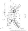
- FIG. 7 is a sectional view of an apparatus for controlling gas layer thickness on the surface of a casting roll in a twin roll strip caster according to the invention.
- FIG. 8 is a plan view of the apparatus for controlling gas layer thickness on the surface of a casting roll in a twin roll strip caster according to the invention.
- FIG. 9 is a perspective view of the apparatus for controlling gas layer thickness on the surface of a casting roll in a twin roll strip caster according to the invention.
- FIG. 10 schematically shows the apparatus for controlling gas layer thickness on the surface of a casting roll in a twin roll strip caster according to the invention along with a gas layer thickness profile.
- FIG. 7 is a sectional view of an apparatus for controlling gas layer thickness on the surface of a casting roll in a twin roll strip caster according to the invention
- FIG. 8 is a plan view of the apparatus for controlling gas layer thickness on the surface of casting rolls in the twin roll strip caster according to the invention
- FIG. 9 is a perspective view of the apparatus for controlling gas layer thickness on the surface of the casting roll in the twin roll strip caster according to the invention
- FIG. 10 schematically shows the apparatus for controlling gas layer thickness on the surface of a casting roll in a twin roll strip caster according to the invention along with a gas layer thickness profile.
- a gas layer thickness control apparatus 90 of the invention is arranged in parallel with casting rolls 1 and 1 a, extending from the front end to the rear end of a meniscus shield 9 covering over a molten metal pool 5 formed between the casting rolls 1 and 1 a and edge dams 2 .
- the control apparatus 90 serves to block introduction of heat transfer resistant particles, that is, foreign materials produced during casting as well as to adjust the thickness and width of gas layers at both ends e ( FIG. 3 ) of the casting roll 1 , 1 a in order to prevent hot banding or bulging at the edges E of the strip 6 ( FIG. 2 ).
- the control apparatus 90 includes chambers 30 , blocking units 40 , operating units 50 and a control unit 60 .
- control apparatus 90 is mounted in a symmetric configuration on both the casting rolls 1 and 1 a , hereinafter description will be made about only a portion of the control apparatus 90 mounted on one of the casting rolls 1 and 1 a by using similar reference numerals to designate similar components.
- the chambers 30 are fixedly mounted on lateral portions of the meniscus shield 9 in a longitudinal direction of the rolls, i.e., a width direction of the strip 6 .
- Each of the chambers 30 is a receiving member having a reverse U-shaped cross section with its opened lower end being opposed to the outer periphery of each of the casting rolls 1 and 1 a .
- the chamber 30 has a length equal to that of the casting roll 1 , 1 a.
- the internal space of the chamber 30 is divided into suction edge portions where suction force is generated and a non-suction central portion where suction force is not generated, in which the operating unit 50 adjusts the width of the suction edge portions in respect to the non-suction central portion.
- the blocking unit 40 shields the molten metal pool from foreign materials such as black layer powder, ceramic powder abraded from the edge dams 2 , oxide scale powder dropped from the surface of the roll so that the foreign materials may not be mixed into the molten metal pool.
- the block unit 40 has a front barrier member 41 detachably assembled to a front portion of the chamber 30 and a rear barrier member 42 detachably assembled to a rear portion of the chamber 30 , in which the front and rear barrier members 41 and 42 each have an underside which is arranged tight close with the outer periphery of the casting roll 1 , 1 a .
- a plurality of bolts 43 b detachably assemble the front barrier member 41 to a reverse L-shaped holder 43 a mounted on a front wall of the chamber 30 and the rear barrier member 42 to another reverse L-shaped holder 43 a mounted on a rear wall of the chamber 30 .
- the front barrier member 41 includes a thin iron plate 41 a in direct face-contact with the outer periphery of the casting roll 1 , 1 a and a permanent magnet 41 b overlying the iron plate 41 a for closely contacting the iron plate 41 a with the casting roll 1 , 1 a under magnetic force.
- the permanent magnet 41 b in the form of a unitary piece or a number of mosaicked plates, is wrapped in a wrapper made of heat resistant cloth sized equal to the iron plate 41 a .
- a heat resistant cover 41 c is arranged on the permanent magnet 41 b to protect the wrapper of the permanent magnet 41 b from damage under hot temperature and thus to prevent demagnetization of the permanent magnet owing to hot molten metal.
- the rear barrier member 42 includes a thin iron plate 42 a and a support 42 b wrapped in a folded lower end of the iron plate 42 a.
- the underside of the iron plate 42 a is in direct facial-contact with the outer periphery of the casting roll 1 , 1 a between a brush roll 7 ( FIG. 1 ) and the rear wall of the chamber 30 , and the lower end of the iron plate 42 a is folded to impart elastic force to the iron plate 42 a so that the iron plate 42 a tightly contacts with the outer periphery of the casting roll 1 , 1 a .
- the support 42 b is vertically movable at both ends.
- another permanent magnet having a predetermined strength level may be provided to the top of the rear barrier member 42 .
- Elastic bodies such as a spring may be installed at the both ends of the support 42 b to elastically support the both ends of the support 42 b downward. Such a configuration serves to block the open air from flowing into the molten metal pool 5 between the casting rolls 1 , 1 a.
- the thin iron plates 41 a and 42 a of the front and rear barrier members 41 and 42 in contact with the casting rolls 1 , 1 a are preferably made of a material, which is same as that of steel to be cast and easily attracted by a magnet.
- the iron plate 41 a is a magnetic substance, even though debris are abraded from the iron plate 41 a in friction with the roll surface owing to inadequate conditions including iron plate thickness, magnetic field strength and suction force of vacuum, the debris are captured by the permanent magnet 41 b without being introduced into molten metal.
- the iron plates 41 a and 42 a are made of a material equal with that of molten metal in the casting process. Then, even if some of the debris produced from abrasion with the casting roll 1 , 1 a are introduced into molten metal, the influence of pollution can be relatively reduced.
- an iron plate of pure iron (100% purity) having clean surfaces is preferably selected for the iron plates 41 a and 42 a.
- the thickness of the thin plates 41 a and 42 a is a very important factor regarding the endurance of the iron plates, roll surface damages and sealing. If the iron plates 41 a and 42 a are too thin, the iron plates. 41 a may be readily torn by protrusions, if any, on the surface of the casting roll 1 , 1 a and thus may not control the gas layer thickness. On the contrary, if the iron plates 41 a and 42 a are too thick, the iron plates 41 a and 42 a may be waved from heat of high temperature. Then, a sharp edge of a waved region may create roll damages such as cracks when the iron plates 41 a and 42 a contact with the roll surface. Therefore, the thin iron plates 41 a and 42 a preferably have a thickness of about 30 to 60 ⁇ m if they are made of any of pure iron, steel and stainless steel.
- the permanent magnet 41 b disposed on the iron plate 41 a has magnet members with a predetermined magnitude of magnetic field strength, which are linearly disposed side by side across the permanent magnet 41 b.
- the magnetic force of the permanent magnet 41 b induces a magnetic force toward the roll surface causing the magnet 41 b to strongly attract the casting roll 1 , 1 a.
- the magnetic force of the permanent magnet 41 b has great effects on the contact state between the thin iron plate 41 a and the casting roll 1 , 1 a and their gas sealing force based upon contact load.
- the permanent magnet 41 b preferably has a suitable value of magnetic field strength in respect to the material and the thickness of the iron plate 41 a. If the magnetic field strength of the permanent magnet 41 b is too small, the contact force between the iron plate 41 a and the roll 1 , 1 a is weak thereby reducing sealing ability for blocking the open air. On the contrary, if the magnetic field strength is too large, the thin iron plate 41 a may damage the surface of the roll 1 , 1 a forming for example scratches, which may cause severe defects on the strip surface such as cracks formed in a longitudinal direction of the strip.
- the magnetic field strength of the permanent magnet 41 b may be varied according to the material and the thickness of the iron plate 41 a, surface conditions of the casting roll 1 , 1 a and the area ratio of the mosaicked permanent magnet 41 b or the thickness of the magnet, the magnetic field strength of the permanent magnet 41 b is most preferably in a range of about 500 to 1500 Oe based upon ferritic magnet members having a thickness of about 2 to 6 mm.
- the wrapper enclosing the permanent magnet 41 b on the iron plate 41 a is made of a heat resistant ceramic cloth capable of sufficiently enduring in a temperature range of about 200 to 500° C.
- the heat resistant cover 41 c is disposed on the wrapper to prevent the wrapper from being directly exposed to hot molten metal and atmospheric gas or subsequently burnt.
- the heat resistant cover 41 c also prevents demagnetization of the permanent magnet 41 b.
- the protective heat resistant cover 41 c is preferably made of a thin iron plate or a ceramic cloth which can sufficiently endure in a high temperature atmosphere.
- a blower 45 is arranged between the rear barrier member 42 and the brush roll 7 , which blows inert gas toward the outer periphery of the casting roll 1 , 1 a along the entire length thereof in order to shield the chamber from the open air and large particles of heat transfer resistant substance such as black layer powder abraded from the roll surface, abraded edge dam powder and fine oxide scale.
- the blower 45 is arranged in parallel with the roll along the entire length of the roll, and has a nozzle 46 with an opened slit 46 a in its underside and a gas feed line 47 for feeding inert gas.
- the slit 46 a of the nozzle 46 has a width of about 50 to 300 ⁇ m while nitrogen gas is fed at a pressure of 4 to 10 bar through the gas feed line 47 and injected from the leading end of the slit 46 a at an injection rate of 30 to 150 m/sec. If nitrogen gas collides into the surface of the casting roll 1 , 1 a at a low rate of about 30 m/sec or less, pollutants such as the heat transfer resistant substance are not readily removed. On the contrary, an excessive quantity of gas may be consumed to raise the injection rate of gas even though a higher injection rate of nitrogen gas is more advantageous. As a result, it is most preferable to inject nitrogen gas under the above condition.
- the operating unit 50 functioning to adjust the thickness and the width of the gas layer at the both ends of the casting roll 1 , 1 a includes a pair of suction lines 51 which communicate by their lower ends with both side portions in the top of the chamber 30 to apply suction force to suction areas in both side portions of the chamber 30 so that suction force can be applied to the both ends e of the casting roll 1 , 1 a.
- Each of the suction lines 51 communicates with a suction pump (not shown), and has an control valve 51 a which is opened/closed by a single action controller 65 .
- the chamber 30 has movable plates 52 installed in its inner space, which are laterally slided in the both side portions of the chamber 30 to adjust the width of the suction areas.
- the movable plates 52 are assembled, respectively, with a pair of operating members 55 which are arranged in non-suction areas and exert driving force to laterally reciprocate the movable plates 52 .
- the movable plates 52 are slidably assembled respectively to a pair of guide bars 53 which are installed within the each chamber 30 so that the movable plates 52 can perform efficient reciprocating motion. From the both ends of the chamber 30 , the movable plates 52 are moved inward up to critical positions which are distanced to 10 through 15 mm from the both ends. The bottom of the each suction line 51 communicates with the chamber 30 between one end and each critical position.
- Each of the operating members 55 maybe formed of a cylinder member, which is arranged in the inner space of the chamber 30 corresponding to the non-suction area and connected by the leading end of its rod to each of the movable plates 52 to horizontally move the each movable plate 52 .
- the each operating member 55 may be formed of a motor member for rotating a screw shaft meshed with a bolt hole.
- the control unit 60 functioning to control the operation of the operating members 55 and the control valves 51 a in the suction lines 51 is installed between an entry pinch roll and a coiler for winding the strip to detect the width and quantity of hot banding or bulging at the both lateral edges of the strip 6 .
- the control unit 60 includes a camera 61 installed in a loop pit right below a roll nip between the casting rolls 1 , 1 a. The camera 61 detects existence of hot banding or bulging and its degree, if any, based upon contrast difference according to temperature variation in a width direction of the strip.
- the control unit 60 also includes a thickness meter 62 installed between the entry pinch roll and the coiler for winding the strip to measure the thickness profile of the strip 6 in a width direction thereof.
- the control unit 60 further includes a controller 63 which is connected with both the camera 61 and the thickness meter 62 to generate a suction force control signal e p and a width control signal e w based upon measured values.
- the controller 63 adjusts the opening ratio of the control valves 51 a in the suction lines 51 , and is connected with the single action controllers 65 which are electrically connected with the operating members 55 to operate the same.
- Each of the single action controllers 65 is connected with each of the operating members 55 to independently control the suction force via the suction line 51 and the width adjustment via the operating member 55 .
- Such a feedback system is adapted to continuously operate on-line during the casting process until hot banding or bulging is completely eliminated from the both edges of the strip.
- fluid is more collectively accumulated in the suction areas We or on the both ends of the casting roll 1 , 1 a compared with the non-suction area Wc in the central portion of roll barrel, and atmospheric gas such as nitrogen or oxygen has a large value of layer thickness in the suction areas We as indicated with a gas profile P in FIG. 10 .
- the external pollutants such as powder abraded from the edge dams 2 and oxide scale powder are heavily accumulated on the ends e of the casting roll according to characteristics of the twin roll strip caster 100 , solidification is delayed at the roll ends e owing to degradation in the cooling ability of the roll compared with at the roll barrel central portion b.
- Such a phenomenon may occur as casting time elapses even though this phenomenon was not observed in an early stage of casting. Time-elapsing is closely related to the above-described fluid accumulation. As a result, where hot banding or bulging takes place at the both edges E, bulging cannot be avoided without enhancing the cooling ability of the suction areas We at the both ends e of the casting roll 1 , 1 a in comparison with that of the non-suction area Wc in the roll barrel central portion b.
- the control apparatus 10 of the invention photographs the strip 6 with the hot strip monitoring camera 61 within the loop pit right below the roll nip to observe an image of the strip 6 .
- the strip 6 is normally cast without hot banding or bulging owing to insufficiently solidified metal at the strip edges, brightness difference is not observed in a width direction of the strip 6 and thus it is understood that the strip 6 is being cast at a uniform temperature (brightness) across its entire width.
- a suction force control signal e p or a width control signal e w is not sent to the suction lines 51 and the operating members 55 via the controller 63 and the single action controller 65 .
- nitrogen gas of high pressure is fed toward the outer periphery of the casting rolls 1 and 1 a by the blower 45 installed between the chamber 30 and the brush roll 7 in order to block introduction of external oxygen or the pollutants including abraded black layer powder, ceramic powder such as abraded edge dam powder and oxide scale powder which may act as heat transfer resistant particles.
- the image photographed by the camera 61 shows brightness difference at the both edges of the strip 6 (in which the edges E of the strip are locally brighter than the central portion B of the strip) thereby to notify hot banding or bulging.
- the width or quantity of hot banding or bulging is measured at the edges E of the strip 6 with the thickness meter arranged at an output side in respect to a casting direction of the strip 6 .
- a measured value of width or quantity is transmitted to the controller 63 , which in response to the value controls the cooling ability at the ends of the casting rolls 1 and 1 a so that the thickness de/dc of the gas layer on the roll surface can be adjusted to form the gas layer profile as designated with the reference number 72 in FIG. 10 .
- control is performed according to conditions suitable to the degree of hot banding or bulging at the edges of the strip 6 , in which a suction force control signal e p and a width control signal e w calculated by the controller 63 are transmitted to the operating members 55 and the control valves 51 a in the suction lines via the single action controller 63 , which is in electrical connection with the controller 63 for individually receiving operation signals therefrom, to adequately control the internal pressure P and the variation of the movable plates in the both lateral spaces of the chamber, thereby adjusting both the thickness de and the width We of the gas layer at the ends of the casting rolls 1 and 1 a.
- the feedback system is adapted to continuously operate on-line until hot banding or bulging owing to insufficiently solidified metal at the both edges of the strip is completely removed.
- the pollutants such as black layer powder abraded from the rolls, abraded edge dam powder and oxide scale powder functioning as heat transfer resistant particles as well as creating cracks on the casting rolls are removed through suction in the suction areas We on the ends of the casting rolls corresponding to the fluid-accumulating portions where the strip edges tend to be insufficiently solidified.
- the thickness of atmospheric gas between the roll and the solidification shell functioning to determine the cooling ability of the casting rolls is adjusted in cooperation with hot banding or bulging on-line during casting so that the gas layer thickness d e on the roll ends and the gas layer thickness d c on the roll barrel central portions are adjusted different from each other through adjustment of the suction force of gas from hermetic spaces at both ends of the rolls and the width of the hermetic spaces.
- the invention can actively and rapidly cope with insufficient solidification as well as improve the quality and yield of the strip and the stability of the operation.
Abstract
Description
δ∝(υx/Vp)1/2
wherein υ is the kinetic viscosity of gas, x is the length of the plate from a leading end, and Vp is the moving rate of the plate.
h=1/(d r /k r +d g /k g +d s /k s +d c /k c) Equation2,
wherein d is thickness, k is heat transfer ratio, subscript r is casting roll, subscript g is gas, subscript s is oxide film on the surface of molten metal, c is ceramic powder such as-oxide scale powder or abraded edge dam powder having a large value of heat transfer resistance.
Claims (21)
Applications Claiming Priority (3)
| Application Number | Priority Date | Filing Date | Title |
|---|---|---|---|
| KR1020010083717 | 2001-12-22 | ||
| KR1020010083717A KR100584751B1 (en) | 2001-12-22 | 2001-12-22 | An apparatus for controlling gas layer thickness on the surface of casting roll in twin roll strip caster |
| PCT/KR2002/002396 WO2003055624A1 (en) | 2001-12-22 | 2002-12-20 | An apparatus for controlling gas layer thickness on the surface of casting roll in twin roll strip caster |
Publications (2)
| Publication Number | Publication Date |
|---|---|
| US20050253314A1 US20050253314A1 (en) | 2005-11-17 |
| US7323135B2 true US7323135B2 (en) | 2008-01-29 |
Family
ID=19717470
Family Applications (1)
| Application Number | Title | Priority Date | Filing Date |
|---|---|---|---|
| US10/499,908 Active 2024-10-15 US7323135B2 (en) | 2001-12-22 | 2002-12-20 | Apparatus for controlling gas layer thickness on the surface of casting rolls in a twin roll strip caster |
Country Status (9)
| Country | Link |
|---|---|
| US (1) | US7323135B2 (en) |
| EP (1) | EP1455973B1 (en) |
| JP (1) | JP3741704B2 (en) |
| KR (1) | KR100584751B1 (en) |
| CN (1) | CN1281359C (en) |
| AU (1) | AU2002359016B2 (en) |
| CA (1) | CA2470700A1 (en) |
| DE (1) | DE60227988D1 (en) |
| WO (1) | WO2003055624A1 (en) |
Cited By (4)
| Publication number | Priority date | Publication date | Assignee | Title |
|---|---|---|---|---|
| US20080303522A1 (en) * | 2004-07-01 | 2008-12-11 | Masaaki Aoki | Magnetic Field Generator |
| US20110020972A1 (en) * | 2009-07-21 | 2011-01-27 | Sears Jr James B | System And Method For Making A Photovoltaic Unit |
| US20120090357A1 (en) * | 2010-10-19 | 2012-04-19 | Takahide Nakamura | Glass film ribbon production method and glass film ribbon production apparatus |
| US20150174649A1 (en) * | 2013-12-24 | 2015-06-25 | Posco | Edge Dam Upper Portion Sealing Apparatus for Twin Roll Strip Caster |
Families Citing this family (17)
| Publication number | Priority date | Publication date | Assignee | Title |
|---|---|---|---|---|
| KR100584751B1 (en) * | 2001-12-22 | 2006-05-30 | 주식회사 포스코 | An apparatus for controlling gas layer thickness on the surface of casting roll in twin roll strip caster |
| JP4424164B2 (en) * | 2004-11-12 | 2010-03-03 | 株式会社Ihi | Sealing device for twin roll casting machine |
| US8312917B2 (en) | 2004-12-13 | 2012-11-20 | Nucor Corporation | Method and apparatus for controlling the formation of crocodile skin surface roughness on thin cast strip |
| US20060124271A1 (en) * | 2004-12-13 | 2006-06-15 | Mark Schlichting | Method of controlling the formation of crocodile skin surface roughness on thin cast strip |
| US7891407B2 (en) | 2004-12-13 | 2011-02-22 | Nucor Corporation | Method and apparatus for localized control of heat flux in thin cast strip |
| JP4804841B2 (en) * | 2005-09-07 | 2011-11-02 | 新日本製鐵株式会社 | Method for producing strip material by continuous casting using melt spinning method |
| KR100977783B1 (en) * | 2007-09-28 | 2010-08-24 | 주식회사 포스코 | Strip edge shape control apparatus and method in strip casting process |
| CN101977728B (en) * | 2008-03-21 | 2012-12-05 | 株式会社Ihi | Roll polishing apparatus |
| JP5255461B2 (en) * | 2009-01-09 | 2013-08-07 | 三菱日立製鉄機械株式会社 | Twin roll type continuous casting machine |
| CN102371349B (en) * | 2010-08-23 | 2013-10-30 | 宝山钢铁股份有限公司 | Method and device for preventing thin-strip continuous casting molten bath surface from contaminating |
| CN103506616A (en) * | 2013-10-23 | 2014-01-15 | 唐山市润捷机械设备制造有限公司 | Online cleaning device for slab continuous casting arc section roller way |
| KR102201304B1 (en) * | 2013-12-19 | 2021-01-11 | 재단법인 포항산업과학연구원 | Facilities for manufacturing strip |
| KR101659810B1 (en) * | 2014-12-10 | 2016-09-28 | 주식회사 포스코 | Twin-Roll Cover Device |
| CN104764408A (en) * | 2015-03-23 | 2015-07-08 | 王威 | Keel molding raw material quality detection device and application method thereof |
| CN108199005B (en) * | 2018-01-03 | 2020-06-23 | 浙江衡远新能源科技有限公司 | Rolling method and equipment for battery pole piece |
| JP7265654B2 (en) | 2019-07-03 | 2023-04-26 | スペイラ ゲゼルシャフト ミット ベシュレンクテル ハフツング | Melt feeding for strip casting system |
| CN115971436B (en) * | 2023-03-16 | 2023-05-26 | 张家港中美超薄带科技有限公司 | Method for controlling convexity of thin strip steel |
Citations (11)
| Publication number | Priority date | Publication date | Assignee | Title |
|---|---|---|---|---|
| JPH0366453A (en) | 1989-08-03 | 1991-03-22 | Nippon Steel Corp | Twin roll type continuous casting machine |
| WO1993022087A1 (en) * | 1992-04-24 | 1993-11-11 | Ishikawajima-Harmia Heavy Industries Company Limited | Vapor extraction in continuous strip casting |
| JPH06297108A (en) | 1993-04-19 | 1994-10-25 | Nippon Steel Corp | Cooling roll in metal strip continuous casting apparatus |
| JPH06328205A (en) | 1993-05-24 | 1994-11-29 | Nippon Steel Corp | Cooling roll in metal strip continuous casting apparatus |
| JPH07276004A (en) | 1994-04-11 | 1995-10-24 | Nippon Steel Corp | Method for controlling crown and thickness of cast slab in twin roll type continuous casting process |
| JPH09103845A (en) | 1995-10-06 | 1997-04-22 | Nippon Steel Corp | Austenitic stainless steel thin slab and its production |
| JPH09327753A (en) | 1996-06-10 | 1997-12-22 | Nippon Steel Corp | Cooling drum of thin cast slab continuous casting apparatus |
| KR19980057611A (en) | 1996-12-30 | 1998-09-25 | 이우복 | Location tracking method of mobile communication terminal |
| JPH1110289A (en) | 1997-06-23 | 1999-01-19 | Ishikawajima Harima Heavy Ind Co Ltd | Twin roll type continuous casting equipment |
| KR19990042986A (en) | 1997-11-28 | 1999-06-15 | 정몽규 | Clutch Operated Oil Supply Device |
| US7021364B2 (en) * | 2001-12-21 | 2006-04-04 | Posco | Apparatus for preventing the contamination of casting rolls and bulging of strip in a twin roll strip caster |
Family Cites Families (12)
| Publication number | Priority date | Publication date | Assignee | Title |
|---|---|---|---|---|
| JPS5662660A (en) * | 1979-10-29 | 1981-05-28 | Hitachi Ltd | Producing equipment of thin metal strip |
| US5103895A (en) * | 1989-07-20 | 1992-04-14 | Nippon Steel Corporation | Method and apparatus of continuously casting a metal sheet |
| JPH0622738B2 (en) * | 1989-08-04 | 1994-03-30 | 新日本製鐵株式会社 | Continuous casting method for thin slabs |
| JP2820301B2 (en) * | 1990-01-19 | 1998-11-05 | 新日本製鐵株式会社 | Thin-wall slab continuous casting method for measuring the thickness of deposits on the casting mold surface and continuous casting method for adjusting casting conditions based on this method |
| JP2925407B2 (en) * | 1992-08-20 | 1999-07-28 | 日立造船株式会社 | Continuous casting equipment with sealing device |
| JPH081284A (en) * | 1994-06-14 | 1996-01-09 | Nippon Steel Corp | Twin roll type continuous casting method and apparatus therefor |
| JP2788197B2 (en) * | 1994-10-07 | 1998-08-20 | 新日本製鐵株式会社 | Drum peripheral cleaning device for twin-drum continuous casting machine |
| FR2727338A1 (en) * | 1994-11-30 | 1996-05-31 | Usinor Sacilor | CONTINUOUS CASTING DEVICE BETWEEN INHERENT COVER CYLINDERS |
| FR2732627B1 (en) * | 1995-04-07 | 1997-04-30 | Usinor Sacilor | METHOD AND DEVICE FOR ADJUSTING THE BOMB OF THE CYLINDERS OF A CASTING SYSTEM OF METAL STRIPS |
| JPH08309489A (en) * | 1995-05-17 | 1996-11-26 | Mitsubishi Heavy Ind Ltd | Twin drum type casting machine |
| KR100605706B1 (en) * | 2001-08-28 | 2006-08-01 | 주식회사 포스코 | Method for preventing hot band of hot strip in twin-roll strip casting process |
| KR100584751B1 (en) * | 2001-12-22 | 2006-05-30 | 주식회사 포스코 | An apparatus for controlling gas layer thickness on the surface of casting roll in twin roll strip caster |
-
2001
- 2001-12-22 KR KR1020010083717A patent/KR100584751B1/en active IP Right Grant
-
2002
- 2002-12-20 CN CNB028218647A patent/CN1281359C/en not_active Expired - Fee Related
- 2002-12-20 WO PCT/KR2002/002396 patent/WO2003055624A1/en active Application Filing
- 2002-12-20 DE DE60227988T patent/DE60227988D1/en not_active Expired - Lifetime
- 2002-12-20 CA CA002470700A patent/CA2470700A1/en not_active Abandoned
- 2002-12-20 EP EP02793492A patent/EP1455973B1/en not_active Expired - Fee Related
- 2002-12-20 AU AU2002359016A patent/AU2002359016B2/en not_active Ceased
- 2002-12-20 JP JP2003556191A patent/JP3741704B2/en not_active Expired - Fee Related
- 2002-12-20 US US10/499,908 patent/US7323135B2/en active Active
Patent Citations (11)
| Publication number | Priority date | Publication date | Assignee | Title |
|---|---|---|---|---|
| JPH0366453A (en) | 1989-08-03 | 1991-03-22 | Nippon Steel Corp | Twin roll type continuous casting machine |
| WO1993022087A1 (en) * | 1992-04-24 | 1993-11-11 | Ishikawajima-Harmia Heavy Industries Company Limited | Vapor extraction in continuous strip casting |
| JPH06297108A (en) | 1993-04-19 | 1994-10-25 | Nippon Steel Corp | Cooling roll in metal strip continuous casting apparatus |
| JPH06328205A (en) | 1993-05-24 | 1994-11-29 | Nippon Steel Corp | Cooling roll in metal strip continuous casting apparatus |
| JPH07276004A (en) | 1994-04-11 | 1995-10-24 | Nippon Steel Corp | Method for controlling crown and thickness of cast slab in twin roll type continuous casting process |
| JPH09103845A (en) | 1995-10-06 | 1997-04-22 | Nippon Steel Corp | Austenitic stainless steel thin slab and its production |
| JPH09327753A (en) | 1996-06-10 | 1997-12-22 | Nippon Steel Corp | Cooling drum of thin cast slab continuous casting apparatus |
| KR19980057611A (en) | 1996-12-30 | 1998-09-25 | 이우복 | Location tracking method of mobile communication terminal |
| JPH1110289A (en) | 1997-06-23 | 1999-01-19 | Ishikawajima Harima Heavy Ind Co Ltd | Twin roll type continuous casting equipment |
| KR19990042986A (en) | 1997-11-28 | 1999-06-15 | 정몽규 | Clutch Operated Oil Supply Device |
| US7021364B2 (en) * | 2001-12-21 | 2006-04-04 | Posco | Apparatus for preventing the contamination of casting rolls and bulging of strip in a twin roll strip caster |
Cited By (8)
| Publication number | Priority date | Publication date | Assignee | Title |
|---|---|---|---|---|
| US20080303522A1 (en) * | 2004-07-01 | 2008-12-11 | Masaaki Aoki | Magnetic Field Generator |
| US7733090B2 (en) * | 2004-07-01 | 2010-06-08 | Hitachi Metals, Ltd. | Magnetic field generator |
| US20110020972A1 (en) * | 2009-07-21 | 2011-01-27 | Sears Jr James B | System And Method For Making A Photovoltaic Unit |
| US7888158B1 (en) | 2009-07-21 | 2011-02-15 | Sears Jr James B | System and method for making a photovoltaic unit |
| US20120090357A1 (en) * | 2010-10-19 | 2012-04-19 | Takahide Nakamura | Glass film ribbon production method and glass film ribbon production apparatus |
| US8656737B2 (en) * | 2010-10-19 | 2014-02-25 | Nippon Electric Glass Co., Ltd. | Glass film ribbon production method and glass film ribbon production apparatus |
| US20150174649A1 (en) * | 2013-12-24 | 2015-06-25 | Posco | Edge Dam Upper Portion Sealing Apparatus for Twin Roll Strip Caster |
| US9216452B2 (en) * | 2013-12-24 | 2015-12-22 | Posco | Edge dam upper portion sealing apparatus for twin roll strip caster |
Also Published As
| Publication number | Publication date |
|---|---|
| DE60227988D1 (en) | 2008-09-11 |
| EP1455973B1 (en) | 2008-07-30 |
| CA2470700A1 (en) | 2003-07-10 |
| CN1281359C (en) | 2006-10-25 |
| AU2002359016B2 (en) | 2008-03-13 |
| WO2003055624A1 (en) | 2003-07-10 |
| KR20030053405A (en) | 2003-06-28 |
| JP2005512819A (en) | 2005-05-12 |
| AU2002359016A1 (en) | 2003-07-15 |
| JP3741704B2 (en) | 2006-02-01 |
| CN1582209A (en) | 2005-02-16 |
| EP1455973A4 (en) | 2006-03-29 |
| EP1455973A1 (en) | 2004-09-15 |
| US20050253314A1 (en) | 2005-11-17 |
| KR100584751B1 (en) | 2006-05-30 |
Similar Documents
| Publication | Publication Date | Title |
|---|---|---|
| US7323135B2 (en) | Apparatus for controlling gas layer thickness on the surface of casting rolls in a twin roll strip caster | |
| AU2006308557A1 (en) | Method and apparatus for electromagnetic confinement of molten metal in horizontal casting systems | |
| US7380583B2 (en) | Belt casting of non-ferrous and light metals and apparatus therefor | |
| KR100518328B1 (en) | An apparatus for controlling the strip edge shape and internal quality in twin roll strip caster | |
| CN112203781B (en) | High friction rolling of thin metal strips | |
| JPS62174326A (en) | Flange cooler for shape material | |
| EP0768131B1 (en) | Method and apparatus of manufacturing a wide metal thin strip | |
| JP3633573B2 (en) | Continuous casting method | |
| KR100605706B1 (en) | Method for preventing hot band of hot strip in twin-roll strip casting process | |
| JPH04266465A (en) | Continuous casting method and continuous casting machine | |
| KR100406375B1 (en) | Method For Manufacturing As-Cast Strip In Strip Casting Process | |
| US7066237B2 (en) | Method of manufacturing austenitic stainless steel sheet cast piece | |
| JP7196318B2 (en) | Short belt side dam for twin belt casting machine | |
| JP3061229B2 (en) | Belt type continuous casting equipment | |
| JP4691839B2 (en) | Steel plate manufacturing method and steel plate manufacturing equipment | |
| EP3878572A1 (en) | Mold for continuous steel casting and continuous steel casting method | |
| KR100470662B1 (en) | Method For Manufacturing Strip By Twin Roll Strip Caster | |
| JP2023141391A (en) | Continuous casting method for steal | |
| JPH0461738B2 (en) | ||
| KR100516465B1 (en) | Apparatus for preventing hot band from forming on strip edge in twin roll strip casting | |
| JPS5916658A (en) | Belt type continuous casting device | |
| KR20030013157A (en) | Methods of manufacturing good quality of strip with twin roll strip casting apparatus and apparatus of vapor blower used therein | |
| JPH04237549A (en) | Method for predicting longitudinal crack of continuously cast slab | |
| JPS58205659A (en) | Continuous casting method of rotary wheel type | |
| JPS63286252A (en) | Twin belt type continuous casting method |
Legal Events
| Date | Code | Title | Description |
|---|---|---|---|
| AS | Assignment |
Owner name: POSCO, KOREA, REPUBLIC OF Free format text: ASSIGNMENT OF ASSIGNORS INTEREST;ASSIGNORS:CHOI, JU-TAE;CHEONG, HAN-NAM;LEE, YONG-GI;REEL/FRAME:016413/0797 Effective date: 20040616 |
|
| AS | Assignment |
Owner name: POSCO 1 KOEDONG-DONG, NAM-KU, KOREA, REPUBLIC OF Free format text: CORRECTIV;ASSIGNORS:CHOI, JU-TAE;CHEONG, HAN-NAM;LEE, YONG-GI (DECEASED);AND OTHERS;REEL/FRAME:017203/0796 Effective date: 20040616 Owner name: RESEARCH INSTITUTE OF INDUSTRIAL SCIENCE & TECHNOL Free format text: CORRECTIV;ASSIGNORS:CHOI, JU-TAE;CHEONG, HAN-NAM;LEE, YONG-GI (DECEASED);AND OTHERS;REEL/FRAME:017203/0796 Effective date: 20040616 |
|
| STCF | Information on status: patent grant |
Free format text: PATENTED CASE |
|
| CC | Certificate of correction | ||
| FEPP | Fee payment procedure |
Free format text: PAYOR NUMBER ASSIGNED (ORIGINAL EVENT CODE: ASPN); ENTITY STATUS OF PATENT OWNER: LARGE ENTITY |
|
| FPAY | Fee payment |
Year of fee payment: 4 |
|
| AS | Assignment |
Owner name: FUJI ELECTRIC COL, LTD., JAPAN Free format text: CHANGE OF NAME;ASSIGNOR:FUJI ELECTRIC DEVICE TECHNOLOGY CO., LTD.;REEL/FRAME:027249/0159 Effective date: 20110720 Owner name: FUJI ELECTRIC CO., LTD., JAPAN Free format text: CHANGE OF NAME;ASSIGNOR:FUJI ELECTRIC DEVICE TECHNOLOGY CO., LTD.;REEL/FRAME:027249/0159 Effective date: 20110720 |
|
| FPAY | Fee payment |
Year of fee payment: 8 |
|
| MAFP | Maintenance fee payment |
Free format text: PAYMENT OF MAINTENANCE FEE, 12TH YEAR, LARGE ENTITY (ORIGINAL EVENT CODE: M1553); ENTITY STATUS OF PATENT OWNER: LARGE ENTITY Year of fee payment: 12 |
|
| AS | Assignment |
Owner name: POSCO HOLDINGS INC., KOREA, REPUBLIC OF Free format text: CHANGE OF NAME;ASSIGNOR:POSCO;REEL/FRAME:061562/0041 Effective date: 20220302 |
|
| AS | Assignment |
Owner name: RESEARCH INSTITUTE OF INDUSTRIAL SCIENCE & TECHNOLOGY, KOREA, REPUBLIC OF Free format text: ASSIGNMENT OF ASSIGNORS INTEREST;ASSIGNORS:POSCO HOLDINGS INC.;RESEARCH INSTITUTE OF INDUSTRIAL SCIENCE & TECHNOLOGY;REEL/FRAME:063212/0033 Effective date: 20221205 Owner name: POSCO CO., LTD, KOREA, REPUBLIC OF Free format text: ASSIGNMENT OF ASSIGNORS INTEREST;ASSIGNORS:POSCO HOLDINGS INC.;RESEARCH INSTITUTE OF INDUSTRIAL SCIENCE & TECHNOLOGY;REEL/FRAME:063212/0033 Effective date: 20221205 |