US7323137B2 - Air sterilizing system - Google Patents
Air sterilizing system Download PDFInfo
- Publication number
- US7323137B2 US7323137B2 US10/666,380 US66638003A US7323137B2 US 7323137 B2 US7323137 B2 US 7323137B2 US 66638003 A US66638003 A US 66638003A US 7323137 B2 US7323137 B2 US 7323137B2
- Authority
- US
- United States
- Prior art keywords
- electron beam
- air
- duct
- beam generator
- flowing
- Prior art date
- Legal status (The legal status is an assumption and is not a legal conclusion. Google has not performed a legal analysis and makes no representation as to the accuracy of the status listed.)
- Expired - Fee Related, expires
Links
Images


Classifications
-
- B—PERFORMING OPERATIONS; TRANSPORTING
- B01—PHYSICAL OR CHEMICAL PROCESSES OR APPARATUS IN GENERAL
- B01D—SEPARATION
- B01D53/00—Separation of gases or vapours; Recovering vapours of volatile solvents from gases; Chemical or biological purification of waste gases, e.g. engine exhaust gases, smoke, fumes, flue gases, aerosols
- B01D53/34—Chemical or biological purification of waste gases
- B01D53/46—Removing components of defined structure
- B01D53/62—Carbon oxides
-
- A—HUMAN NECESSITIES
- A61—MEDICAL OR VETERINARY SCIENCE; HYGIENE
- A61L—METHODS OR APPARATUS FOR STERILISING MATERIALS OR OBJECTS IN GENERAL; DISINFECTION, STERILISATION OR DEODORISATION OF AIR; CHEMICAL ASPECTS OF BANDAGES, DRESSINGS, ABSORBENT PADS OR SURGICAL ARTICLES; MATERIALS FOR BANDAGES, DRESSINGS, ABSORBENT PADS OR SURGICAL ARTICLES
- A61L9/00—Disinfection, sterilisation or deodorisation of air
- A61L9/16—Disinfection, sterilisation or deodorisation of air using physical phenomena
- A61L9/18—Radiation
-
- B—PERFORMING OPERATIONS; TRANSPORTING
- B01—PHYSICAL OR CHEMICAL PROCESSES OR APPARATUS IN GENERAL
- B01D—SEPARATION
- B01D49/00—Separating dispersed particles from gases, air or vapours by other methods
-
- B—PERFORMING OPERATIONS; TRANSPORTING
- B01—PHYSICAL OR CHEMICAL PROCESSES OR APPARATUS IN GENERAL
- B01D—SEPARATION
- B01D53/00—Separation of gases or vapours; Recovering vapours of volatile solvents from gases; Chemical or biological purification of waste gases, e.g. engine exhaust gases, smoke, fumes, flue gases, aerosols
- B01D53/007—Separation of gases or vapours; Recovering vapours of volatile solvents from gases; Chemical or biological purification of waste gases, e.g. engine exhaust gases, smoke, fumes, flue gases, aerosols by irradiation
-
- B—PERFORMING OPERATIONS; TRANSPORTING
- B01—PHYSICAL OR CHEMICAL PROCESSES OR APPARATUS IN GENERAL
- B01D—SEPARATION
- B01D53/00—Separation of gases or vapours; Recovering vapours of volatile solvents from gases; Chemical or biological purification of waste gases, e.g. engine exhaust gases, smoke, fumes, flue gases, aerosols
- B01D53/34—Chemical or biological purification of waste gases
- B01D53/46—Removing components of defined structure
- B01D53/48—Sulfur compounds
- B01D53/50—Sulfur oxides
-
- B—PERFORMING OPERATIONS; TRANSPORTING
- B01—PHYSICAL OR CHEMICAL PROCESSES OR APPARATUS IN GENERAL
- B01D—SEPARATION
- B01D53/00—Separation of gases or vapours; Recovering vapours of volatile solvents from gases; Chemical or biological purification of waste gases, e.g. engine exhaust gases, smoke, fumes, flue gases, aerosols
- B01D53/34—Chemical or biological purification of waste gases
- B01D53/46—Removing components of defined structure
- B01D53/54—Nitrogen compounds
- B01D53/56—Nitrogen oxides
-
- B—PERFORMING OPERATIONS; TRANSPORTING
- B01—PHYSICAL OR CHEMICAL PROCESSES OR APPARATUS IN GENERAL
- B01D—SEPARATION
- B01D53/00—Separation of gases or vapours; Recovering vapours of volatile solvents from gases; Chemical or biological purification of waste gases, e.g. engine exhaust gases, smoke, fumes, flue gases, aerosols
- B01D53/34—Chemical or biological purification of waste gases
- B01D53/46—Removing components of defined structure
- B01D53/60—Simultaneously removing sulfur oxides and nitrogen oxides
-
- F—MECHANICAL ENGINEERING; LIGHTING; HEATING; WEAPONS; BLASTING
- F24—HEATING; RANGES; VENTILATING
- F24F—AIR-CONDITIONING; AIR-HUMIDIFICATION; VENTILATION; USE OF AIR CURRENTS FOR SCREENING
- F24F8/00—Treatment, e.g. purification, of air supplied to human living or working spaces otherwise than by heating, cooling, humidifying or drying
- F24F8/20—Treatment, e.g. purification, of air supplied to human living or working spaces otherwise than by heating, cooling, humidifying or drying by sterilisation
-
- Y—GENERAL TAGGING OF NEW TECHNOLOGICAL DEVELOPMENTS; GENERAL TAGGING OF CROSS-SECTIONAL TECHNOLOGIES SPANNING OVER SEVERAL SECTIONS OF THE IPC; TECHNICAL SUBJECTS COVERED BY FORMER USPC CROSS-REFERENCE ART COLLECTIONS [XRACs] AND DIGESTS
- Y02—TECHNOLOGIES OR APPLICATIONS FOR MITIGATION OR ADAPTATION AGAINST CLIMATE CHANGE
- Y02A—TECHNOLOGIES FOR ADAPTATION TO CLIMATE CHANGE
- Y02A50/00—TECHNOLOGIES FOR ADAPTATION TO CLIMATE CHANGE in human health protection, e.g. against extreme weather
- Y02A50/20—Air quality improvement or preservation, e.g. vehicle emission control or emission reduction by using catalytic converters
Definitions
- Air circulation systems for example, air conditioning and heating systems in buildings and aircraft, have been known to circulate airborne viruses and bacteria, spreading sickness to the occupants. This is becoming a concern to both the manufacturers of such systems as well as the occupants.
- Some air circulation systems in buildings are beginning to address this problem by including an air sterilization system therein for sterilizing the air.
- the air is sterilized by irradiating the circulating air with ultraviolet lights.
- a drawback of this method is that the sterilization process is dependent upon the time of exposure to the ultraviolet light, and therefore, the effectiveness decreases with increasing air velocity.
- dust collecting on the ultraviolet lights reduces the intensity of the ultraviolet light that irradiates the air, which further reduces the effectiveness of the sterilization process.
- the present invention provides a system for sterilizing air that is more effective than prior methods, and includes a duct for flowing the air therethrough.
- a first electron beam generator is positioned relative to the duct for irradiating the air flowing therethrough with a first electron beam.
- the first electron beam disables or kills microorganisms within the air such as viruses, bacteria, fungi, etc., to sterilize the air.
- an air circulator for causing air to flow through the duct can be included.
- the system can be in or form an air circulation system.
- a converter is positioned within the duct downstream from the first electron beam generator for converting ozone within the air into oxygen.
- a reflector is in the duct opposite to the first electron beam generator for reflecting the first electron beam.
- a second electron beam generator is positioned relative to the duct opposite to the first electron beam generator for irradiating the air flowing through the duct with a second electron beam.
- the duct has two right angle turns on opposite sides of the first electron beam generator for providing shielding from radiation. This duct can be collimated.
- the present invention is also directed to a method of sterilizing air which includes flowing the air through a duct and irradiating the air flowing through the duct with a first electron beam from a first electron beam generator.
- the first electron beam disables microorganisms within the air to sterilize the air.
- the sterilization can occur in an air circulation system.
- the present invention is directed to a method for sterilizing air including flowing the air through a duct and irradiating the flowing air with opposed first and second electron beams from first and second electron beam generators for disabling microorganisms in the air.
- the first and second electron beam generators are positioned relative to the duct opposite from each other.
- the present invention is further directed to a method of sterilizing air including directing an electron beam into a sterilization chamber.
- the air is directed into the sterilization chamber generally against the direction of the electron beam and is redirected generally along the direction of the electron beam for irradiating the air and disabling microorganisms in the air.
- an electron beam to sterilize air in the present invention provides more effective sterilization of flowing air than prior methods such as irradiation with ultraviolet light because electron beams can disable or kill microorganisms more rapidly.
- electron beams are affected by dust to a lesser degree than ultraviolet light. Consequently, the present invention can effectively sterilize air flowing at high flow rates.
- FIG. 1 is a perspective schematic drawing of an embodiment of the present invention air sterilizing system.
- FIG. 2 is graph depicting the energy distribution for a single electron beam directed into air.
- FIG. 3 is a graph depicting the energy distribution for two opposing electron beams directed into air as well as the combined energy distribution of the two beams.
- FIG. 4 is a perspective schematic view of another embodiment of the present invention air sterilizing system.
- FIG. 5 is a graph depicting the energy distribution for a single electron beam directed into air, the distribution of energy that is reflected by a reflector positioned in the path of the electron beam, and the combined energy distribution of the electron beam and the reflected energy.
- FIG. 6 is a side schematic view of still another embodiment of the present invention air sterilizing system.
- FIG. 7 is a side schematic view of yet another embodiment of the present invention air sterilizing system.
- FIG. 8 is a side schematic view of still another embodiment of the present invention air sterilizing system.
- FIG. 9 is a side schematic view of another embodiment of the present invention air sterilizing system.
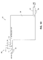
- FIG. 10 is a schematic drawing of air entering an enclosed volume that is sterilized by an embodiment of the present invention air sterilizing system.
- FIG. 11 is a schematic drawing of air within an enclosed volume being sterilized by an embodiment of the present invention air sterilizing system in a recirculatory manner.
- FIG. 12 is a perspective drawing of yet another embodiment of the present invention air sterilizing system.
- FIG. 13 is a schematic side sectional view of another embodiment of the present invention.
- FIG. 14 is an enlargement of the bottom portion of FIG. 13 .
- FIG. 15 is a schematic top view of the reaction chamber of FIG. 13 .
- air sterilizing system 10 is employed for sterilizing breathable air and is often incorporated into or included in an air circulation system such as an air conditioning and/or heating system for killing microorganisms within the circulated air, for example, viruses, bacteria and fungi (including yeasts and molds), as well as pollen, etc.
- Air sterilizing system 10 can also be employed to circulate air just for sterilization purposes.
- Air sterilizing system 10 includes an air duct 12 which air circulates through in the direction of the arrows.
- Two electron beam generators 14 are positioned on opposite sides of the air duct 12 , for directing electrons e 31 from opposed electron beams 13 into the flowing air in an irradiation zone 11 between the electron beam generators 14 .
- the electron beam generators 14 are sized to provide complete electron beam coverage over the cross-section (width and height) of air duct 12 so that virtually all the air flowing through the air duct 12 passes through the electron beams 13 .
- the electron beams 13 disable or kill airborne microorganisms flowing in the air by damaging the DNA and/or structural matter, thereby sterilizing the air. Any X-rays formed by electrons e 31 striking the walls of air duct 12 may also help disable some of the microorganisms.
- a converter 16 is located with air duct 12 downstream from the electron beam generators 14 for converting ozone (O 3 ) produced in the sterilization process back into oxygen (O 2 ). Consequently, when the treated air is introduced into an area occupied by people, sterile breathable air is provided.
- the electron beams 13 are emitted into air duct 12 from the electron beam generators 14 through exit beam windows 14 a located at the distal ends of the electron beam generators 14 .
- the width of air duct 12 is commonly about the same as the width of the exit beam windows 14 a of electron beam generators 14 .
- the air duct 12 has two opposed holes 12 a which are configured with the proper size and shape to allow the electron beams 13 to enter the air duct 12 .
- the electron beam generators 14 are mounted to air duct 12 along a common axis X and in a sealed manner which prevents radiation from escaping to the exterior of air duct 12 .
- the electron beam generators 14 are preferably similar to those disclosed in U.S.
- the air duct 12 is about 8-12 inches wide by about 5-6 inches high in order to obtain a sufficient air flow rate.
- air duct 12 is about 10 inches wide by about 5 inches wide and the electron beam generators 14 have an exit beam window 14 a with dimensions of about 10 inches by 3 inches.
- the electron beam generators 14 sized for such a duct typically operate at about 125 kV.
- electron beam generators 14 can be used that have a circular exit window 14 a that is about 2 inches in diameter and operate at about 80 kV to 100 kV.
- two electron beam generators 14 operating at about 125 kV are often employed because, as can be seen in FIG. 2 , the energy distribution or dose of a single electron beam 13 decreases dramatically as the electron beam 13 travels through air for an electron beam generator 14 operating at about 125 kV.
- the electron beam 13 dose from a single electron beam generator 14 operating at about 125 kV is relatively constant for about the first 11 ⁇ 2 inches of travel through air, but then drops rapidly at distances that are over 11 ⁇ 2 inches. Consequently, when operating at about 125 kV, in order to obtain consistent sterilization of the air flowing through an air duct 12 that is about 10 inches by 5 inches, two opposed electron beam generators 14 are desirable.
- FIG. 3 shows that two electron beam generators 14 operating at about 125 kV which are positioned opposite to each other about five inches apart combine to produce a relatively constant energy distribution in the air within irradiation zone 11 of air duct 12 .
- the two electron beam generators 14 are depicted as being aligned along a common axis X, alternatively, one electron beam generator 14 can be positioned or staggered downstream of the other.
- the second electron beam generator 14 may be omitted.
- the second electron beam generator 14 may also be omitted in a higher air duct 12 (for example, 5 inches high) where consistent or total sterilization is not required.
- air duct 12 needs to be higher than 5 inches, higher power electron beam generators 14 than those specified above can be employed. In addition, lower power electron beam generators can be employed for smaller air ducts 12 .
- the width of the electron beam generators 14 can be varied to accommodate air ducts 12 of different widths. For air ducts 12 that have dimensions that are wider than the electron beam generators 14 , more than one electron beam generator 14 can be mounted side by side to irradiate the full width. The configuration of such side by side electron beam generators 14 can be aligned with each other or staggered.
- multiple successive electron beam generators 14 can be mounted to air duct 12 in the direction of the air flow. As a result, air flowing through air duct 12 would be irradiated by successive electron beams 13 thereby lengthening the time of irradiation to obtain the desired level of irradiation.
- Converter 16 is commonly a reactive catalytic filter having a pellet bed for converting ozone flowing therethrough into oxygen.
- the pellet bed typically includes spherical manganese dioxide pellets.
- the pellets are typically formed of platinum.
- the converter 16 is often positioned adjacent to the electron beam generators 14 as shown but, alternatively, can be positioned near the exit of air duct 12 .
- ozone within the flowing air formed by the electron e ⁇ irradiation can react with or neutralize any other microorganisms or contaminants that are on the walls of the air duct 12 downstream from the electron beam generators 14 . In some cases, it may be desirable to omit converter 16 altogether.
- Typical uses for air sterilizing system 10 are in the air circulation systems of aircraft as well as hospitals, for example, the main air circulation system, or the circulation systems for surgery or recovery rooms.
- Other uses include systems for hotels, schools, theaters, underground mines, malls, submarines, ships, motorized vehicles, etc.
- air sterilizing system 25 is another embodiment of the present invention which differs from air sterilizing system 10 in that a single electron beam generator 14 is employed for generating a single electron beam 13 and a reflector 15 is positioned within air duct 12 on the wall opposite to the electron beam generator 14 .
- the electron beam generator 14 and the reflector 15 are positioned along axis X with the irradiation zone 11 occupying the space or area therebetween.
- Some of the electrons e ⁇ from the electron beam 13 strike the reflector 15 and are reflected back into the air flowing through air duct 12 within irradiation zone 11 .
- reflector 15 is formed from a high density material having a high Z number such as lead, or tungsten, etc.
- Reflector 15 can be mounted within air duct 12 or, alternatively, the air duct 12 itself can be formed of the high density material at least in the region surrounding irradiation zone 11 . Referring to FIG. 5 , it can be seen that the electron beam 13 and the energy reflected by the reflector 15 combine to produce a relatively constant energy distribution in the air within irradiation zone 11 .
- the graph of FIG. 5 depicts a relatively constant energy distribution for an air duct 12 having a depth or height of about 2.5 inches from the electron beam generator 14 . This dimension can be increased when using an electron beam generator 14 of greater power.
- air sterilizing system 22 is similar to air sterilizing system 10 , differing in that air duct 12 includes two vertical legs 18 and horizontal legs 20 extending from a central duct portion 12 a on opposite sides of the electron beam generators 14 for providing shielding from X-rays generated by the system.
- the zig zag path configuration of the legs 18 and 20 does not provide a straight path for X-rays to escape from either the entrance or exit of air duct 12 .
- Horizontal legs 20 are typically parallel to central duct portion 12 a while vertical legs 18 are at a right angle.
- Air duct 12 including legs 18 / 20 , may be formed of lead or steel.
- air sterilizing system 26 differs from air sterilizing system 22 in that system 26 includes a collimation system 24 consisting of a series of small ducts 24 a of laminated lead or steel extending through legs 18 / 20 into central duct portion 12 a in a zig zag configuration. This provides better shielding of X-rays and allows the legs 18 / 20 and central duct portion 12 a to be made much smaller than that required for air sterilizing system 22 .
- the legs 18 / 20 of air sterilizing system 26 may be less than one half the size of those in system 22 .
- the converter 16 for converting ozone into oxygen is shown to be downstream from the collimation ducts 24 a but, alternatively, can be upstream.
- Both air sterilizing systems 22 and 26 may also include any of the features or variations previously discussed above in regard to air sterilizing systems 10 and 25 .
- legs 18 / 20 can be formed at angles that are not right angles and still be in a zig zag configuration.
- air sterilizing system 30 includes an air circulator 32 such as a blower or fan for generating the air flow through air duct 12 past electron beam generators 14 .
- a distribution junction 28 allows the sterilized air to be distributed into a series of smaller ducts 28 a for distribution.
- a single converter 16 is shown before junction 28 for converting ozone into oxygen but, alternatively, a series of converters 16 can be positioned within each duct 28 a.
- air sterilizing system 34 differs from air sterilizing system 30 in that instead of employing two large electron beam generators 14 within air duct 12 , system 34 includes a series of small electron beam generators 14 positioned along each individual duct 28 a .
- Each duct 28 a may be employed for providing air to an individual user or to separate zones.
- the ducts 28 a are narrow enough so that only one electron beam generator 14 is required for each duct 28 a but two may be used if the air ducts 28 a are made larger.
- reflectors 15 may be employed.
- Both air sterilizing systems 30 and 34 can include any of the features or variations previously discussed above in regard to air sterilizing systems 10 , 22 , 25 and 26 .
- an enclosed volume 36 such as a room, hall, cabin, or building, has an air sterilizing system 35 with an air sterilizing intake system 38 for providing fresh sterilized air into the volume 36 .
- the intake system 38 is schematically shown with only one electron beam generator 14 for simplicity and is typically similar to either air sterilizing system 10 ( FIG. 1 ), 25 ( FIG. 4 ), 22 ( FIG. 6 ) or 26 ( FIG. 7 ).
- An air circulator 32 forces the air into the volume 36 . Air is circulated out of the volume 36 by another air circulator 32 through exhaust duct 42 .
- the intake system 38 can be similar to either air sterilizing system 30 ( FIG. 8 ) or air sterilizing system 34 ( FIG. 9 ).
- volume 36 is relatively air tight, one of the air circulators 32 can be omitted.
- the intake system 38 is shown to be at the top of volume 36 and the exhaust duct 42 at the bottom, the position and level of either can be varied to suit the situation at hand.
- an air sterilizing system 40 is employed within the volume 36 for circulating and sterilizing air contained within the volume 36 .
- Air sterilizing system 40 can be similar to air sterilizing systems 10 , 25 , 22 or 26 .
- air sterilizing system 40 can be similar to either air sterilizing system 30 or 34 .
- the intake and exhaust of air sterilizing system 40 are shown to be near each other, alternatively, the intake and exhaust can be distantly positioned, such as on opposite sides of volume 36 .
- no intake or exhaust ducts into and out of volume 36 are depicted in FIG. 11 , alternatively actively powered or passive intake/exhaust ducts or vents can be included.
- air sterilizing system 45 is yet another embodiment of the present invention that can be employed for sterilizing air flowing through a circular conduit or duct 44 .
- System 45 includes a rectangular duct portion 48 to which opposed electron beam generators 14 are mounted.
- duct portion 48 has a lower height than duct 44 , but is greater in width. This allows electron beam generators 14 to be employed for sufficiently treating air flowing through duct 44 with electron beams 13 which ordinarily would not have a high enough power for penetrating deeply enough through the flowing air in duct 44 to obtain sufficient treatment.
- Transition portions 46 connect duct portions 48 to the duct 44 on opposite sides of duct portion 48 .
- Transition portions 46 have a height that decreases moving from duct 44 to duct portion 48 and a width that increases moving from duct 44 to duct portion 48 .
- transition portions 46 have angled top, bottom and side walls, but alternatively, the walls can be curved.
- Electron beam generators 14 are abutted in side by side relation in order to provide continuous electron beam coverage across the width of duct portion 48 .
- One or more additional rows of electron beam emitters 14 can be positioned in the direction of flow to lengthen the time of irradiation, as shown. If the height of the duct portion 48 is low enough, a single unopposed row of electron beam emitters 14 can be employed.
- a converter 16 is not depicted in FIG. 12 , it is understood that such a feature can be included in system 45 .
- the angled transition portions 46 can be employed when using two opposed electron beam generators 14 or a single electron beam generator 14 .
- Air sterilizing system 50 is yet another embodiment of the present invention which is suitable for treating relatively small flow rates.
- System 50 includes a small low power electron beam generator 14 that is mounted to a reaction or sterilization chamber 52 .
- Electron beam generator 14 includes a cylindrical housing 54 having an exit window 14 a at one end.
- An electron gun 56 positioned within the housing generates electrons e ⁇ which are accelerated through exit window 14 a in an electron beam 13 .
- the distal end of the housing 54 of electron beam generator 14 is mounted to reaction chamber 52 in a manner where the exit window 14 a is positioned and sealed over the interior cavity 52 a of reaction chamber 52 so that electrons e ⁇ generated by electron gun 56 can be accelerated through exit window 14 a into cavity 52 a .
- Reaction chamber 52 has an inlet 58 through which flowing air enters.
- a nozzle 62 ( FIGS. 14 and 15 ) is positioned at or near the end of inlet 58 for directing a jet of air into the cavity 52 a towards exit window 14 a with the central axis of the jet being substantially perpendicular to exit window 14 a and generally axially or along the same direction as electron beam 13 .
- the nozzle 62 is centrally positioned at the bottom of cavity 52 a opposite to exit window 14 a for uniformly directing the air towards exit window 14 a .
- the intensity of the electron beam 13 into the flowing air increases from close to zero at the bottom of cavity 52 a to about full intensity adjacent exit window 14 a . Consequently, the irradiation zone 11 in the area near exit window 14 a has the highest intensity of electrons e ⁇ .
- the air is treated by the electron beam 13 in the irradiation zone 11 as it flows toward exit window 14 a and then flows away from exit window 14 a into a series of outlets 64 equally positioned about or around nozzle 62 .
- the air is irradiated in both the forward and backward flow directions with the increasing and decreasing electron beam irradiation intensity combining to result in relatively uniform irradiation. Consequently, cavity 52 a acts as a reverse flow duct in which the flow of air reverses direction.
- four outlets 64 are employed.
- the outlets 64 are in communication with a chamber 66 which is connected to the outlet 68 of reaction chamber 52 through which the treated air flows.
- electron beam generator 14 can have a 2 inch diameter exit window 14 a and operate at about 60 kV with reaction chamber 52 having a cavity 52 a of about 2 inches in diameter by about 2 inches high.
- any separating or filter devices 16 would be positioned downstream from the outlet 68 of reaction chamber 52 .
- Inlet 58 , nozzle 62 , cavity 52 a , outlets 64 , chamber 66 and outlet 68 , including connections to inlet 58 and outlet 68 can be considered to form a continuous duct.
- a series of small electron beam generators 14 may encircle a circular or an annular shaped air duct for radially directing a series of electron beams therein.
- electron beam generators 14 can be positioned on all four sides. It is understood that the air ducts described above can be rectangular, polygonal, circular or curved in cross section, and that the dimensions or cross sectional area can be varied depending upon the application at hand. Also, the size and capacity of the electron beam generators 14 can be varied to suit particular applications.
- FIGS. 2 , 3 and 5 are for electron beam generators 14 operating at about 125 kV, the shape of the curves is similar for any operating voltage or power. Additionally, various features of the air sterilizing systems described above may be combined, substituted or omitted. In all the air sterilizing systems described above, a general filter for capturing large particles and debris can be positioned upstream of the electron beam generators 14 . An air circulator 32 can be positioned either upstream or downstream of the electron beam generators 14 , or both. In some cases, some or all air circulators 32 may be omitted if circulation can be provided through the air ducts by other means, such as natural air currents.
- the air sterilization systems of the present invention can be part of or be within an air circulation system, or can be itself an air circulation system.
Abstract
Description
Claims (27)
Priority Applications (3)
| Application Number | Priority Date | Filing Date | Title |
|---|---|---|---|
| US10/666,380 US7323137B2 (en) | 2000-06-20 | 2003-09-19 | Air sterilizing system |
| US11/122,334 US7189978B2 (en) | 2000-06-20 | 2005-05-04 | Air sterilizing system |
| US11/703,620 US7547892B2 (en) | 2000-06-20 | 2007-02-07 | Air sterilizing system |
Applications Claiming Priority (3)
| Application Number | Priority Date | Filing Date | Title |
|---|---|---|---|
| US21335800P | 2000-06-20 | 2000-06-20 | |
| US09/883,861 US6623706B2 (en) | 2000-06-20 | 2001-06-18 | Air sterilizing system |
| US10/666,380 US7323137B2 (en) | 2000-06-20 | 2003-09-19 | Air sterilizing system |
Related Parent Applications (1)
| Application Number | Title | Priority Date | Filing Date |
|---|---|---|---|
| US09/883,861 Division US6623706B2 (en) | 2000-06-20 | 2001-06-18 | Air sterilizing system |
Related Child Applications (1)
| Application Number | Title | Priority Date | Filing Date |
|---|---|---|---|
| US11/122,334 Continuation-In-Part US7189978B2 (en) | 2000-06-20 | 2005-05-04 | Air sterilizing system |
Publications (2)
| Publication Number | Publication Date |
|---|---|
| US20040060811A1 US20040060811A1 (en) | 2004-04-01 |
| US7323137B2 true US7323137B2 (en) | 2008-01-29 |
Family
ID=26908002
Family Applications (2)
| Application Number | Title | Priority Date | Filing Date |
|---|---|---|---|
| US09/883,861 Expired - Fee Related US6623706B2 (en) | 2000-06-20 | 2001-06-18 | Air sterilizing system |
| US10/666,380 Expired - Fee Related US7323137B2 (en) | 2000-06-20 | 2003-09-19 | Air sterilizing system |
Family Applications Before (1)
| Application Number | Title | Priority Date | Filing Date |
|---|---|---|---|
| US09/883,861 Expired - Fee Related US6623706B2 (en) | 2000-06-20 | 2001-06-18 | Air sterilizing system |
Country Status (10)
| Country | Link |
|---|---|
| US (2) | US6623706B2 (en) |
| EP (1) | EP1296749B1 (en) |
| JP (1) | JP2003535665A (en) |
| CN (1) | CN1447713A (en) |
| AT (1) | ATE286427T1 (en) |
| AU (1) | AU2001269914A1 (en) |
| BR (1) | BR0112188A (en) |
| DE (1) | DE60108248T2 (en) |
| RU (1) | RU2003102372A (en) |
| WO (1) | WO2001097953A2 (en) |
Cited By (4)
| Publication number | Priority date | Publication date | Assignee | Title |
|---|---|---|---|---|
| US20070145291A1 (en) * | 2000-06-20 | 2007-06-28 | Tzvi Avnery | Air sterilizing system |
| US20070158499A1 (en) * | 2003-06-06 | 2007-07-12 | David Whittingham | Aircraft air disinfection system |
| US20090184262A1 (en) * | 2006-03-20 | 2009-07-23 | Fraunhofer-Gesellschaft Zur Foerderung Angewandten Forschung E.V. | Device and method for altering the characteristics of three-dimensional shaped parts using electrons and use of said method |
| US20100202932A1 (en) * | 2009-02-10 | 2010-08-12 | Danville Dennis R | Air movement system and air cleaning system |
Families Citing this family (8)
| Publication number | Priority date | Publication date | Assignee | Title |
|---|---|---|---|---|
| US6623706B2 (en) * | 2000-06-20 | 2003-09-23 | Advanced Electron Beams, Inc. | Air sterilizing system |
| JP2002286251A (en) * | 2001-01-11 | 2002-10-03 | Mitsubishi Heavy Ind Ltd | Air supply system, method for eliminating fungi from air, and conveyance system and method |
| US20090160309A1 (en) * | 2005-10-15 | 2009-06-25 | Dirk Burth | Electron beam exit window |
| US7771672B2 (en) * | 2005-12-17 | 2010-08-10 | Airinspace B.V. | Air purification device |
| US8003058B2 (en) * | 2006-08-09 | 2011-08-23 | Airinspace B.V. | Air purification devices |
| AU2007333954B2 (en) * | 2006-12-13 | 2013-06-06 | Gentherm Medical, Llc | Fluid disinfection unit for patient temperature control system |
| WO2009009683A1 (en) * | 2007-07-11 | 2009-01-15 | Stokely-Van Camp, Inc. | Active sterilization zone for container filling |
| US8740600B1 (en) * | 2007-10-09 | 2014-06-03 | Isopur Technologies, Inc. | Apparatus for agglomerating particles in a non-conductive liquid |
Citations (60)
| Publication number | Priority date | Publication date | Assignee | Title |
|---|---|---|---|---|
| US3105733A (en) * | 1961-07-25 | 1963-10-01 | Reginald Robbins | Apparatus for sterilizing air |
| US3779706A (en) | 1971-10-04 | 1973-12-18 | Energy Sciences Inc | Process for bulk sterilization, minimizing chemical and physical damage |
| US3869362A (en) | 1973-01-11 | 1975-03-04 | Ebara Mfg | Process for removing noxious gas pollutants from effluent gases by irradiation |
| US4167466A (en) | 1976-12-27 | 1979-09-11 | Accelerators, Inc. | Ozone generation apparatus and method |
| US4244712A (en) | 1979-03-05 | 1981-01-13 | Tongret Stewart R | Cleansing system using treated recirculating air |
| US4324759A (en) | 1979-07-11 | 1982-04-13 | Ebara Corp | Apparatus for treating waste gas by irradiation with electron beams |
| US4396580A (en) * | 1981-03-18 | 1983-08-02 | Avco Everett Research Laboratory, Inc. | Fluid-dynamic means for efficaceous use of ionizing beams in treating process flows |
| US4507265A (en) | 1978-12-29 | 1985-03-26 | Ebara Corporation | Apparatus for treating effluent gas by irradiation with electron beams |
| GB2173779A (en) | 1985-04-16 | 1986-10-22 | Polymer Physik Gmbh | Apparatus for the desulphurisation and denitration of exhaust gases by electron irradiation |
| US4752450A (en) | 1985-07-11 | 1988-06-21 | Leybold-Heraeus Gmbh | Apparatus for cleaning sulphur and nitrogen containing flue gas |
| JPS63302924A (en) | 1987-06-04 | 1988-12-09 | Ebara Corp | Electron beam irradiation treatment device for exhaust gas |
| US4882020A (en) | 1987-05-30 | 1989-11-21 | Ebara Corporation | Process for treating effluent gas |
| US4915916A (en) | 1986-04-24 | 1990-04-10 | Ebara Corporation | Method of and apparatus for treating waste gas by irradiation with electron beam |
| US4961830A (en) * | 1987-10-30 | 1990-10-09 | Ebara Corporation | Method of inhibiting adhesion of by-product inside duct in treatment of waste gas by electron beam irradiation |
| US4969984A (en) | 1987-06-01 | 1990-11-13 | Ebara Corporation | Exhaust gas treatment process using irradiation |
| US5015442A (en) | 1988-02-29 | 1991-05-14 | Tokai Kogyo Co., Ltd. | Sterilizing/deodorizing apparatus |
| US5041271A (en) | 1987-12-10 | 1991-08-20 | Ebara Corporation | Method of treating waste gas by irradiation with electron beam |
| US5112370A (en) | 1989-12-13 | 1992-05-12 | Michele Gazzano | Device for sterilizing a forced air flow by means of ultraviolet radiations |
| EP0579105A1 (en) | 1992-07-09 | 1994-01-19 | Kabushiki Kaisha Toshiba | Apparatus and method for removing carbon dioxide contained in exhaust gas |
| US5319211A (en) | 1992-09-08 | 1994-06-07 | Schonberg Radiation Corp. | Toxic remediation |
| US5357291A (en) | 1992-09-08 | 1994-10-18 | Zapit Technology, Inc. | Transportable electron beam system and method |
| US5368816A (en) * | 1992-04-28 | 1994-11-29 | Kesslertech Gmbh | Conditioning air for human use |
| US5378898A (en) | 1992-09-08 | 1995-01-03 | Zapit Technology, Inc. | Electron beam system |
| US5382410A (en) | 1991-03-11 | 1995-01-17 | In-Vironmental Integrity, Inc. | Electrostatic vapor/aerosol generator with method and apparatus for conditioning building spaces |
| US5445798A (en) | 1992-11-24 | 1995-08-29 | Mitsubishi Denki Kabushiki Kaisha | Microbe propagation preventing apparatus and microbe propagation preventing method |
| US5457269A (en) | 1992-09-08 | 1995-10-10 | Zapit Technology, Inc. | Oxidizing enhancement electron beam process and apparatus for contaminant treatment |
| US5468356A (en) | 1991-08-23 | 1995-11-21 | The United States Of America As Represented By The Secretary Of The Navy | Large scale purification of contaminated air |
| US5468454A (en) | 1994-04-05 | 1995-11-21 | Samsung Electronics Co., Ltd. | Compact sterilizing deodorizing and freshness-preserving apparatus for use in a refrigerator |
| US5573730A (en) | 1995-05-09 | 1996-11-12 | Gillum; Theodore J. | Method and apparatus for treating airborne residues |
| US5582807A (en) | 1994-11-04 | 1996-12-10 | Tek-Kol | Method and apparatus for removing particulate and gaseous pollutants from a gas stream |
| WO1997001386A1 (en) | 1995-06-27 | 1997-01-16 | Coral S.P.A. | A method and apparatus for purifying a gaseous mixture including molecules and/or cells of toxic or polluting substances |
| US5656242A (en) | 1995-06-07 | 1997-08-12 | L2B Environmental Systems Inc. | Air purifier device |
| US5693195A (en) | 1994-06-03 | 1997-12-02 | Ebara Corporation | Method of irradiation with electron beams |
| US5700311A (en) | 1996-04-30 | 1997-12-23 | Spencer; Dwain F. | Methods of selectively separating CO2 from a multicomponent gaseous stream |
| US5702572A (en) | 1995-11-27 | 1997-12-30 | Ebara Corporation | Method for treating exhaust gases and foul water |
| US5756054A (en) | 1995-06-07 | 1998-05-26 | Primex Technologies Inc. | Ozone generator with enhanced output |
| US5759487A (en) | 1995-06-13 | 1998-06-02 | Samsung Electronics Co., Ltd. | Method and apparatus for sterilizing and collecting dust in an air conditioner |
| US5801387A (en) | 1996-03-28 | 1998-09-01 | Electron Processing Systems, Inc. | Method of and apparatus for the electron beam treatment of powders and aggregates in pneumatic transfer |
| US5811014A (en) | 1996-11-12 | 1998-09-22 | Sanitrol Systems, Inc. | Hazardous flowable waste sanitizing and remediating process and apparatus |
| US5834722A (en) | 1994-12-12 | 1998-11-10 | Ebara Corporation | Method and apparatus for treating waste gases by exposure to electron beams |
| US5837207A (en) | 1997-04-17 | 1998-11-17 | Engineering Dynamics Limited | Portable germicidal air filter |
| US5853680A (en) | 1995-10-03 | 1998-12-29 | Mitsubishi Jukogyo Kabushiki Kaisha | Process for the removal of highly concentrated carbon dioxide from high-pressure natural gas |
| US5861127A (en) | 1997-07-11 | 1999-01-19 | Yeh; Kuo Chung | Portable air purifying apparatus |
| US5894130A (en) | 1997-08-08 | 1999-04-13 | Aquatron, Inc. | Ultraviolet sterilization unit |
| US5925320A (en) * | 1997-06-04 | 1999-07-20 | Jones; John P. | Air purification system |
| US5933702A (en) * | 1995-09-06 | 1999-08-03 | Universal Air Technology | Photocatalytic air disinfection |
| US5939026A (en) | 1997-01-31 | 1999-08-17 | Hitachi, Ltd. | Apparatus for processing gas by electron beam |
| US5993612A (en) | 1996-12-13 | 1999-11-30 | L'air Liquide, Societe Anonyme Pour L'etude Et L'exploitation Des Procedes Georges Claude | Process for purifying a gas and apparatus for the implementation of such a process |
| GB2341094A (en) | 1998-09-07 | 2000-03-08 | Aea Technology Plc | Treatment of cabin air |
| US6077488A (en) | 1998-03-19 | 2000-06-20 | The Boc Group, Inc. | Method and apparatus for producing clean dry air having application to air separation |
| US6080281A (en) | 1994-04-18 | 2000-06-27 | Attia; Yosry A. | Scrubbing of contaminants from contaminated air streams with aerogel materials with optional photocatalytic destruction |
| WO2000064499A1 (en) | 1999-04-27 | 2000-11-02 | Ectium Bv | Method for treating a gaseous medium containing contaminating particles |
| US6179968B1 (en) | 1996-07-25 | 2001-01-30 | Ebara Corporation | Method and apparatus for treating gas by irradiation of electron beam |
| US6210642B1 (en) * | 1998-07-27 | 2001-04-03 | Enex, Co., Ltd. | Apparatus for cleaning harmful gas by irradiation with electron beams |
| US6328937B1 (en) | 1999-10-26 | 2001-12-11 | Mark Glazman | Apparatus for killing microorganisms |
| US20020005345A1 (en) | 2000-06-20 | 2002-01-17 | Advanced Electron Beams, Inc. | Gas conversion system |
| US20020011405A1 (en) | 2000-06-20 | 2002-01-31 | Advanced Electron Beams, Inc. | Air sterilizing system |
| US20030086831A1 (en) | 2001-11-02 | 2003-05-08 | Horton Isaac B | Air UV disinfection device and method |
| EP1376021A1 (en) | 2001-01-11 | 2004-01-02 | Mitsubishi Heavy Industries, Ltd. | Air feed system, air dezymotizing method, and system and method for transfer |
| US6893610B1 (en) | 1997-11-21 | 2005-05-17 | Ronald L. Barnes | Air purifier |
Family Cites Families (4)
| Publication number | Priority date | Publication date | Assignee | Title |
|---|---|---|---|---|
| JPS5388656A (en) * | 1977-01-17 | 1978-08-04 | Ebara Corp | Irradiating method for gaseous material with electron beam |
| JPS53106752A (en) * | 1977-03-02 | 1978-09-18 | Toho Rayon Co Ltd | Reinforcing material and its composition for molding product |
| JP2538985B2 (en) * | 1988-04-21 | 1996-10-02 | 三菱重工業株式会社 | Circulating air sterilization / deodorization system |
| JPH08192026A (en) * | 1995-01-18 | 1996-07-30 | Nissin High Voltage Co Ltd | Stack gas treating device by electron beam |
-
2001
- 2001-06-18 US US09/883,861 patent/US6623706B2/en not_active Expired - Fee Related
- 2001-06-19 BR BR0112188-0A patent/BR0112188A/en not_active Application Discontinuation
- 2001-06-19 JP JP2002503427A patent/JP2003535665A/en active Pending
- 2001-06-19 EP EP01948470A patent/EP1296749B1/en not_active Expired - Lifetime
- 2001-06-19 WO PCT/US2001/019551 patent/WO2001097953A2/en active IP Right Grant
- 2001-06-19 AT AT01948470T patent/ATE286427T1/en not_active IP Right Cessation
- 2001-06-19 DE DE60108248T patent/DE60108248T2/en not_active Expired - Lifetime
- 2001-06-19 CN CN01814227A patent/CN1447713A/en active Pending
- 2001-06-19 RU RU2003102372/15A patent/RU2003102372A/en not_active Application Discontinuation
- 2001-06-19 AU AU2001269914A patent/AU2001269914A1/en not_active Abandoned
-
2003
- 2003-09-19 US US10/666,380 patent/US7323137B2/en not_active Expired - Fee Related
Patent Citations (70)
| Publication number | Priority date | Publication date | Assignee | Title |
|---|---|---|---|---|
| US3105733A (en) * | 1961-07-25 | 1963-10-01 | Reginald Robbins | Apparatus for sterilizing air |
| US3779706A (en) | 1971-10-04 | 1973-12-18 | Energy Sciences Inc | Process for bulk sterilization, minimizing chemical and physical damage |
| US3869362B1 (en) | 1973-01-11 | 1984-05-22 | ||
| US3869362A (en) | 1973-01-11 | 1975-03-04 | Ebara Mfg | Process for removing noxious gas pollutants from effluent gases by irradiation |
| US4167466A (en) | 1976-12-27 | 1979-09-11 | Accelerators, Inc. | Ozone generation apparatus and method |
| US4507265A (en) | 1978-12-29 | 1985-03-26 | Ebara Corporation | Apparatus for treating effluent gas by irradiation with electron beams |
| US4244712A (en) | 1979-03-05 | 1981-01-13 | Tongret Stewart R | Cleansing system using treated recirculating air |
| US4324759A (en) | 1979-07-11 | 1982-04-13 | Ebara Corp | Apparatus for treating waste gas by irradiation with electron beams |
| US4396580A (en) * | 1981-03-18 | 1983-08-02 | Avco Everett Research Laboratory, Inc. | Fluid-dynamic means for efficaceous use of ionizing beams in treating process flows |
| GB2173779A (en) | 1985-04-16 | 1986-10-22 | Polymer Physik Gmbh | Apparatus for the desulphurisation and denitration of exhaust gases by electron irradiation |
| US4752450A (en) | 1985-07-11 | 1988-06-21 | Leybold-Heraeus Gmbh | Apparatus for cleaning sulphur and nitrogen containing flue gas |
| US4915916A (en) | 1986-04-24 | 1990-04-10 | Ebara Corporation | Method of and apparatus for treating waste gas by irradiation with electron beam |
| US5015443A (en) | 1986-04-24 | 1991-05-14 | Ebara Corporation | Method of and apparatus for treating waste gas by irradiation with electron beam |
| US4882020A (en) | 1987-05-30 | 1989-11-21 | Ebara Corporation | Process for treating effluent gas |
| US4969984A (en) | 1987-06-01 | 1990-11-13 | Ebara Corporation | Exhaust gas treatment process using irradiation |
| JPS63302924A (en) | 1987-06-04 | 1988-12-09 | Ebara Corp | Electron beam irradiation treatment device for exhaust gas |
| US4961830A (en) * | 1987-10-30 | 1990-10-09 | Ebara Corporation | Method of inhibiting adhesion of by-product inside duct in treatment of waste gas by electron beam irradiation |
| US5041271A (en) | 1987-12-10 | 1991-08-20 | Ebara Corporation | Method of treating waste gas by irradiation with electron beam |
| US5015442A (en) | 1988-02-29 | 1991-05-14 | Tokai Kogyo Co., Ltd. | Sterilizing/deodorizing apparatus |
| US5112370A (en) | 1989-12-13 | 1992-05-12 | Michele Gazzano | Device for sterilizing a forced air flow by means of ultraviolet radiations |
| US5382410A (en) | 1991-03-11 | 1995-01-17 | In-Vironmental Integrity, Inc. | Electrostatic vapor/aerosol generator with method and apparatus for conditioning building spaces |
| US5468356A (en) | 1991-08-23 | 1995-11-21 | The United States Of America As Represented By The Secretary Of The Navy | Large scale purification of contaminated air |
| US5368816A (en) * | 1992-04-28 | 1994-11-29 | Kesslertech Gmbh | Conditioning air for human use |
| US5770785A (en) | 1992-07-09 | 1998-06-23 | Kabushiki Kaisha Toshiba | Apparatus and method for removing carbon dioxide contained in exhaust gas |
| EP0579105A1 (en) | 1992-07-09 | 1994-01-19 | Kabushiki Kaisha Toshiba | Apparatus and method for removing carbon dioxide contained in exhaust gas |
| US5539212A (en) | 1992-09-08 | 1996-07-23 | Zapit Technology, Inc. | Toxic remediation system and method |
| US5378898A (en) | 1992-09-08 | 1995-01-03 | Zapit Technology, Inc. | Electron beam system |
| US5357291A (en) | 1992-09-08 | 1994-10-18 | Zapit Technology, Inc. | Transportable electron beam system and method |
| US5744811A (en) | 1992-09-08 | 1998-04-28 | Zapit Technology, Inc. | Transportable electron beam system and method |
| US5457269A (en) | 1992-09-08 | 1995-10-10 | Zapit Technology, Inc. | Oxidizing enhancement electron beam process and apparatus for contaminant treatment |
| US5319211A (en) | 1992-09-08 | 1994-06-07 | Schonberg Radiation Corp. | Toxic remediation |
| US5523577A (en) | 1992-09-08 | 1996-06-04 | Zapit Technology, Inc. | Electron beam system |
| US5527459A (en) | 1992-11-24 | 1996-06-18 | Mitsubishi Denki Kabushiki Kaisha | Microbe propagation preventing apparatus |
| US5484570A (en) | 1992-11-24 | 1996-01-16 | Mitsubishi Denki Kabushiki Kaisha | Microbe propagation prenvention method |
| US5445798A (en) | 1992-11-24 | 1995-08-29 | Mitsubishi Denki Kabushiki Kaisha | Microbe propagation preventing apparatus and microbe propagation preventing method |
| US5468454A (en) | 1994-04-05 | 1995-11-21 | Samsung Electronics Co., Ltd. | Compact sterilizing deodorizing and freshness-preserving apparatus for use in a refrigerator |
| US6080281A (en) | 1994-04-18 | 2000-06-27 | Attia; Yosry A. | Scrubbing of contaminants from contaminated air streams with aerogel materials with optional photocatalytic destruction |
| US5693195A (en) | 1994-06-03 | 1997-12-02 | Ebara Corporation | Method of irradiation with electron beams |
| US5582807A (en) | 1994-11-04 | 1996-12-10 | Tek-Kol | Method and apparatus for removing particulate and gaseous pollutants from a gas stream |
| US5834722A (en) | 1994-12-12 | 1998-11-10 | Ebara Corporation | Method and apparatus for treating waste gases by exposure to electron beams |
| US5573730A (en) | 1995-05-09 | 1996-11-12 | Gillum; Theodore J. | Method and apparatus for treating airborne residues |
| US5656242A (en) | 1995-06-07 | 1997-08-12 | L2B Environmental Systems Inc. | Air purifier device |
| US5756054A (en) | 1995-06-07 | 1998-05-26 | Primex Technologies Inc. | Ozone generator with enhanced output |
| US5759487A (en) | 1995-06-13 | 1998-06-02 | Samsung Electronics Co., Ltd. | Method and apparatus for sterilizing and collecting dust in an air conditioner |
| WO1997001386A1 (en) | 1995-06-27 | 1997-01-16 | Coral S.P.A. | A method and apparatus for purifying a gaseous mixture including molecules and/or cells of toxic or polluting substances |
| US5933702A (en) * | 1995-09-06 | 1999-08-03 | Universal Air Technology | Photocatalytic air disinfection |
| US5853680A (en) | 1995-10-03 | 1998-12-29 | Mitsubishi Jukogyo Kabushiki Kaisha | Process for the removal of highly concentrated carbon dioxide from high-pressure natural gas |
| US5702572A (en) | 1995-11-27 | 1997-12-30 | Ebara Corporation | Method for treating exhaust gases and foul water |
| US5801387A (en) | 1996-03-28 | 1998-09-01 | Electron Processing Systems, Inc. | Method of and apparatus for the electron beam treatment of powders and aggregates in pneumatic transfer |
| US5700311A (en) | 1996-04-30 | 1997-12-23 | Spencer; Dwain F. | Methods of selectively separating CO2 from a multicomponent gaseous stream |
| US6179968B1 (en) | 1996-07-25 | 2001-01-30 | Ebara Corporation | Method and apparatus for treating gas by irradiation of electron beam |
| US5811014A (en) | 1996-11-12 | 1998-09-22 | Sanitrol Systems, Inc. | Hazardous flowable waste sanitizing and remediating process and apparatus |
| US5993612A (en) | 1996-12-13 | 1999-11-30 | L'air Liquide, Societe Anonyme Pour L'etude Et L'exploitation Des Procedes Georges Claude | Process for purifying a gas and apparatus for the implementation of such a process |
| US5939026A (en) | 1997-01-31 | 1999-08-17 | Hitachi, Ltd. | Apparatus for processing gas by electron beam |
| US5837207A (en) | 1997-04-17 | 1998-11-17 | Engineering Dynamics Limited | Portable germicidal air filter |
| US5925320A (en) * | 1997-06-04 | 1999-07-20 | Jones; John P. | Air purification system |
| US5861127A (en) | 1997-07-11 | 1999-01-19 | Yeh; Kuo Chung | Portable air purifying apparatus |
| US5894130A (en) | 1997-08-08 | 1999-04-13 | Aquatron, Inc. | Ultraviolet sterilization unit |
| US6893610B1 (en) | 1997-11-21 | 2005-05-17 | Ronald L. Barnes | Air purifier |
| US6077488A (en) | 1998-03-19 | 2000-06-20 | The Boc Group, Inc. | Method and apparatus for producing clean dry air having application to air separation |
| US6210642B1 (en) * | 1998-07-27 | 2001-04-03 | Enex, Co., Ltd. | Apparatus for cleaning harmful gas by irradiation with electron beams |
| GB2341094A (en) | 1998-09-07 | 2000-03-08 | Aea Technology Plc | Treatment of cabin air |
| WO2000064499A1 (en) | 1999-04-27 | 2000-11-02 | Ectium Bv | Method for treating a gaseous medium containing contaminating particles |
| US6328937B1 (en) | 1999-10-26 | 2001-12-11 | Mark Glazman | Apparatus for killing microorganisms |
| US20020005345A1 (en) | 2000-06-20 | 2002-01-17 | Advanced Electron Beams, Inc. | Gas conversion system |
| US20020011405A1 (en) | 2000-06-20 | 2002-01-31 | Advanced Electron Beams, Inc. | Air sterilizing system |
| US6623706B2 (en) | 2000-06-20 | 2003-09-23 | Advanced Electron Beams, Inc. | Air sterilizing system |
| EP1376021A1 (en) | 2001-01-11 | 2004-01-02 | Mitsubishi Heavy Industries, Ltd. | Air feed system, air dezymotizing method, and system and method for transfer |
| US20040147214A1 (en) | 2001-01-11 | 2004-07-29 | Yukihiko Oono | Air feed system, air dezymotizing method, and system and method for transfer |
| US20030086831A1 (en) | 2001-11-02 | 2003-05-08 | Horton Isaac B | Air UV disinfection device and method |
Non-Patent Citations (2)
| Title |
|---|
| Darici, Y., et al., "Electron Beam Dissociation of CO and CO<SUB>2 </SUB>on ZnS Thin Films," J. Vac. Sci. Technol. A, 17(3), 692-697 (1999). |
| Tian, C., and Vidal, C.R., "Single to Quadruple Ionization of CO<SUB>2 </SUB>Due to Electron Impact," Phys. Rev. A, 58(5): 3783-3795 (1998). |
Cited By (6)
| Publication number | Priority date | Publication date | Assignee | Title |
|---|---|---|---|---|
| US20070145291A1 (en) * | 2000-06-20 | 2007-06-28 | Tzvi Avnery | Air sterilizing system |
| US7547892B2 (en) * | 2000-06-20 | 2009-06-16 | Advanced Electron Beams, Inc. | Air sterilizing system |
| US20070158499A1 (en) * | 2003-06-06 | 2007-07-12 | David Whittingham | Aircraft air disinfection system |
| US20090184262A1 (en) * | 2006-03-20 | 2009-07-23 | Fraunhofer-Gesellschaft Zur Foerderung Angewandten Forschung E.V. | Device and method for altering the characteristics of three-dimensional shaped parts using electrons and use of said method |
| US8178858B2 (en) * | 2006-03-20 | 2012-05-15 | Fraunhofer-Gesellschaft Zur Foerderung Der Andgewandten Forschung E.V. | Device and method for altering the characteristics of three-dimensional shaped parts using electrons and use of said method |
| US20100202932A1 (en) * | 2009-02-10 | 2010-08-12 | Danville Dennis R | Air movement system and air cleaning system |
Also Published As
| Publication number | Publication date |
|---|---|
| EP1296749B1 (en) | 2005-01-05 |
| RU2003102372A (en) | 2004-07-10 |
| EP1296749A2 (en) | 2003-04-02 |
| DE60108248T2 (en) | 2006-03-16 |
| ATE286427T1 (en) | 2005-01-15 |
| BR0112188A (en) | 2003-05-20 |
| US20020011405A1 (en) | 2002-01-31 |
| US20040060811A1 (en) | 2004-04-01 |
| AU2001269914A1 (en) | 2002-01-02 |
| US6623706B2 (en) | 2003-09-23 |
| DE60108248D1 (en) | 2005-02-10 |
| JP2003535665A (en) | 2003-12-02 |
| CN1447713A (en) | 2003-10-08 |
| WO2001097953A2 (en) | 2001-12-27 |
| WO2001097953A3 (en) | 2002-05-23 |
Similar Documents
| Publication | Publication Date | Title |
|---|---|---|
| US7547892B2 (en) | Air sterilizing system | |
| US7323137B2 (en) | Air sterilizing system | |
| US20100170779A1 (en) | Gas conversion system | |
| US7407633B2 (en) | Method and apparatus for air treatment | |
| US3107974A (en) | Method and systme for the prevention of the spread of infectious disease by airbornemicroorganisms | |
| EP1977771A1 (en) | Photocatalytic air treatment system and method | |
| US20090280027A1 (en) | Photocatalytic air treatment system and method | |
| KR101676817B1 (en) | Radiation type space sterilizer | |
| US6228327B1 (en) | Apparatus and method for simultaneously germicidally cleansing air and water | |
| US20220040363A1 (en) | Systems and Methods for Air Treatment Using UV Irradiation | |
| US6337483B1 (en) | Apparatus and method for simultaneously germicidally cleansing both air and water | |
| US20220170651A1 (en) | Method and system for air ventilation, sterilization and filtration | |
| US20230201406A1 (en) | Laser systems, methods and devices of processing and sanitizing air flow and surfaces | |
| DE102020003124A1 (en) | Virus protection device for an air flow / ventilation device or ventilation system or air conditioning system | |
| US20220034531A1 (en) | Air sanitizer with boundlessly-extended sanitizing chamber and method of using same | |
| JP2003294897A (en) | Device and method for irradiating object with charged particle beam | |
| JP7158768B1 (en) | UV air sterilizer | |
| KR102285032B1 (en) | Sterilization Device Using Laser | |
| WO2023004176A1 (en) | Continuous disinfection device | |
| JP2004041381A (en) | Sterilizer and sterilization type air-conditioning system | |
| JP2004290261A (en) | Electron beam irradiation system |
Legal Events
| Date | Code | Title | Description |
|---|---|---|---|
| CC | Certificate of correction | ||
| AS | Assignment |
Owner name: ADVANCED ELECTRON BEAMS, INC., MASSACHUSETTS Free format text: CHANGE OF NAME;ASSIGNOR:ADVANCED ELECTRON BEAMS, INC.;REEL/FRAME:023292/0528 Effective date: 20050912 Owner name: ADVANCED ELECTRON BEAMS, INC., MASSACHUSETTS Free format text: ASSIGNMENT OF ASSIGNORS INTEREST;ASSIGNOR:AVNERY, TZVI;REEL/FRAME:023282/0940 Effective date: 20010831 |
|
| AS | Assignment |
Owner name: COMERICA BANK, A TEXAS BANKING ASSOCIATION,MICHIGA Free format text: SECURITY AGREEMENT;ASSIGNOR:ADVANCED ELECTRON BEAMS, INC.;REEL/FRAME:024342/0354 Effective date: 20100428 Owner name: COMERICA BANK, A TEXAS BANKING ASSOCIATION, MICHIG Free format text: SECURITY AGREEMENT;ASSIGNOR:ADVANCED ELECTRON BEAMS, INC.;REEL/FRAME:024342/0354 Effective date: 20100428 |
|
| AS | Assignment |
Owner name: COMERICA BANK,MICHIGAN Free format text: SECURITY AGREEMENT;ASSIGNOR:ADVANCED ELECTRON BEAMS, INC.;REEL/FRAME:024358/0415 Effective date: 20100428 Owner name: COMERICA BANK, MICHIGAN Free format text: SECURITY AGREEMENT;ASSIGNOR:ADVANCED ELECTRON BEAMS, INC.;REEL/FRAME:024358/0415 Effective date: 20100428 |
|
| FEPP | Fee payment procedure |
Free format text: PAYOR NUMBER ASSIGNED (ORIGINAL EVENT CODE: ASPN); ENTITY STATUS OF PATENT OWNER: LARGE ENTITY |
|
| REMI | Maintenance fee reminder mailed | ||
| LAPS | Lapse for failure to pay maintenance fees | ||
| STCH | Information on status: patent discontinuation |
Free format text: PATENT EXPIRED DUE TO NONPAYMENT OF MAINTENANCE FEES UNDER 37 CFR 1.362 |
|
| FP | Lapsed due to failure to pay maintenance fee |
Effective date: 20120129 |
|
| AS | Assignment |
Owner name: ADVANCED ELECTRON BEAMS, INC., MASSACHUSETTS Free format text: RELEASE AND REASSIGNMENT OF PATENTS AND PATENT APPLICATIONS;ASSIGNOR:COMERICA BANK;REEL/FRAME:028222/0468 Effective date: 20120515 |
|
| AS | Assignment |
Owner name: HITACHI ZOSEN CORPORATION, JAPAN Free format text: ASSIGNMENT OF ASSIGNORS INTEREST;ASSIGNOR:ADVANCED ELECTRON BEAMS, INC.;REEL/FRAME:028528/0223 Effective date: 20120426 |