US7331764B1 - High-strength low-weight fan blade assembly - Google Patents
High-strength low-weight fan blade assembly Download PDFInfo
- Publication number
- US7331764B1 US7331764B1 US10/827,601 US82760104A US7331764B1 US 7331764 B1 US7331764 B1 US 7331764B1 US 82760104 A US82760104 A US 82760104A US 7331764 B1 US7331764 B1 US 7331764B1
- Authority
- US
- United States
- Prior art keywords
- hub
- fan
- assembly
- phase
- fan blade
- Prior art date
- Legal status (The legal status is an assumption and is not a legal conclusion. Google has not performed a legal analysis and makes no representation as to the accuracy of the status listed.)
- Active, expires
Links
Images


Classifications
-
- F—MECHANICAL ENGINEERING; LIGHTING; HEATING; WEAPONS; BLASTING
- F04—POSITIVE - DISPLACEMENT MACHINES FOR LIQUIDS; PUMPS FOR LIQUIDS OR ELASTIC FLUIDS
- F04D—NON-POSITIVE-DISPLACEMENT PUMPS
- F04D29/00—Details, component parts, or accessories
- F04D29/26—Rotors specially for elastic fluids
- F04D29/32—Rotors specially for elastic fluids for axial flow pumps
- F04D29/325—Rotors specially for elastic fluids for axial flow pumps for axial flow fans
- F04D29/329—Details of the hub
-
- F—MECHANICAL ENGINEERING; LIGHTING; HEATING; WEAPONS; BLASTING
- F04—POSITIVE - DISPLACEMENT MACHINES FOR LIQUIDS; PUMPS FOR LIQUIDS OR ELASTIC FLUIDS
- F04D—NON-POSITIVE-DISPLACEMENT PUMPS
- F04D29/00—Details, component parts, or accessories
- F04D29/02—Selection of particular materials
- F04D29/023—Selection of particular materials especially adapted for elastic fluid pumps
-
- F—MECHANICAL ENGINEERING; LIGHTING; HEATING; WEAPONS; BLASTING
- F04—POSITIVE - DISPLACEMENT MACHINES FOR LIQUIDS; PUMPS FOR LIQUIDS OR ELASTIC FLUIDS
- F04D—NON-POSITIVE-DISPLACEMENT PUMPS
- F04D29/00—Details, component parts, or accessories
- F04D29/26—Rotors specially for elastic fluids
- F04D29/32—Rotors specially for elastic fluids for axial flow pumps
- F04D29/34—Blade mountings
-
- F—MECHANICAL ENGINEERING; LIGHTING; HEATING; WEAPONS; BLASTING
- F04—POSITIVE - DISPLACEMENT MACHINES FOR LIQUIDS; PUMPS FOR LIQUIDS OR ELASTIC FLUIDS
- F04D—NON-POSITIVE-DISPLACEMENT PUMPS
- F04D29/00—Details, component parts, or accessories
- F04D29/26—Rotors specially for elastic fluids
- F04D29/32—Rotors specially for elastic fluids for axial flow pumps
- F04D29/38—Blades
- F04D29/388—Blades characterised by construction
-
- F—MECHANICAL ENGINEERING; LIGHTING; HEATING; WEAPONS; BLASTING
- F05—INDEXING SCHEMES RELATING TO ENGINES OR PUMPS IN VARIOUS SUBCLASSES OF CLASSES F01-F04
- F05D—INDEXING SCHEME FOR ASPECTS RELATING TO NON-POSITIVE-DISPLACEMENT MACHINES OR ENGINES, GAS-TURBINES OR JET-PROPULSION PLANTS
- F05D2300/00—Materials; Properties thereof
- F05D2300/40—Organic materials
- F05D2300/43—Synthetic polymers, e.g. plastics; Rubber
-
- F—MECHANICAL ENGINEERING; LIGHTING; HEATING; WEAPONS; BLASTING
- F05—INDEXING SCHEMES RELATING TO ENGINES OR PUMPS IN VARIOUS SUBCLASSES OF CLASSES F01-F04
- F05D—INDEXING SCHEME FOR ASPECTS RELATING TO NON-POSITIVE-DISPLACEMENT MACHINES OR ENGINES, GAS-TURBINES OR JET-PROPULSION PLANTS
- F05D2300/00—Materials; Properties thereof
- F05D2300/60—Properties or characteristics given to material by treatment or manufacturing
- F05D2300/603—Composites; e.g. fibre-reinforced
Definitions
- the invention relates generally to cooling fan assemblies and, more specifically, to engine cooling fans with thermoset-resin composite fan blades.
- fan blades have been developed for use in automotive cooling systems.
- the fan blades operate to produce a flow of air over heat exchangers to cool the engine.
- the fan blades of an engine-cooling fan must be capable of withstanding the harsh temperature and chemical conditions present in an engine environment.
- engine cooling fans be formed with minimal mass, since fan mass is generally inversely related to the operating life of other operationally related engine fan drive components, such as bearings, the water pump, and the like. It is, therefore, desired that engine cooling fan blades be designed to be both chemically and mechanically durable materials, as well as being lightweight as possible.
- a prior art metal spider fan 10 which is a metal disk or hub 12 from which a plurality of twisted legs 14 a extend, is provided to which a plurality of fan blades 30 are attached.
- the legs 14 a are twisted to provide an appropriate angular displacement for the blades 30 , which are fastened to the spider legs 14 a , typically by bolts, welds, or rivets.
- the spider legs 14 a Due to the forces experienced by the spider legs 14 a , the spider legs typically require a stress relieving treatment as a step in the spider manufacturing process, to minimize the introduction of weaknesses in the form of excess embrittlement through strain hardening, small cracks or other imperfections inherent in the spider leg twist operation that could impair the structural integrity of the fan and thus shorten the operating life of the fan.
- Certain other prior art fan blades as shown in FIG. 2 , have been constructed of thermoplastic materials, such as injection-molded nylon. These prior art blades include short reinforcing fibers dispersed in a thermoplastic matrix, and are used to form entire, unitarily molded fan assemblies (i.e., hubs with multiple contiguously formed fan blades extending therefrom) via a high-pressure injection molding process. These fans, while lighter than comparably strong metal fan assemblies, still suffer from the drawbacks of requiring relatively expensive molds for use in costly injection molding processes. Moreover, in order to alter the geometry of the fan blades, an entire new fan must be molded, thereby requiring a new, separate mold.
- the present invention relates to a engine cooling fan assembly including a generally circular hub member to which a plurality of elongated fan blade members are directly connected.
- Each respective fan blade member includes a hub-connecting portion, a transition portion and a blade portion and is formed from a composite material including a thermoset resin matrix phase and a dispersed continuous fiber reinforcement phase.
- One object of the present invention is to provide an improved engine cooling fan blade. Related objects and advantages of the present invention will be apparent from the following description.
- FIG. 1 is a perspective view of a prior art engine cooling spider and fan blade assembly.
- FIG. 2 is a perspective view of a prior art injection-molded nylon fan blade.
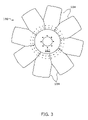
- FIG. 3 is a top plan view of a fan blade assembly including a hub portion to which a plurality of independently formed fan blade portions are directly connected, according to a first preferred embodiment of the present invention.
- FIG. 4 is a perspective view of the embodiment of FIG. 3 .
- FIG. 5A is a side elevational view of FIG. 3 including mechanical fasteners.
- FIG. 5B is a side elevational view of FIG. 3 including an adhesive fastener.
- FIG. 6 is a perspective view of the hub portion of the embodiment of FIG. 3 .
- FIG. 7 is a rear perspective view of a fan blade portion of the embodiment of FIG. 3 .
- FIG. 8 is a front perspective view of FIG. 7 .
- FIG. 9 is a perspective view of another embodiment of a fan blade assembly including a hub portion to which a two pluralities of independently formed fan blade portions characterized by first and second dissimilar pitch angles are directly connected.
- FIGS. 3-8 relate to a first embodiment of the present invention, an axial fan blade system 100 suitable for engine cooling purposes.
- the fan blade system 100 incorporates a generally circular or annular hub disc 102 to which fan blade members 104 may be fastened.
- the fan blade members 104 are preferably spaced substantially evenly about the hub disc 102 for most anticipated systems 100 , although other blade configurations are possible.
- the fan blades 104 are preferably formed from thermoset resin composite materials with a reinforcing fiber phase typically substantially evenly dispersed in a resin matrix phase, and are more preferably composed of a vinyl ester, thermoset resin matrix incorporating a continuous fiber supporting phase.
- the preferred formation process is molding, with the entire blade 104 formed at once.
- the reinforcing phase is preferably a continuous strand material and is more preferably in the form of a fabric, woven or mat material. While the reinforcing phase is still more preferably a continuous strand vitreous or glass fabric, any continuous fibrous or fibrous fabric material may be chosen.
- Such fan blades 104 have less mass (i.e., are lighter in weight) than conventional steel or aluminum blades while having comparable strength.
- the blades 104 also preferably have densities of between about 85 and 125 pounds per cubic foot, and more preferably of about 100 pounds per cubic foot.
- the composite fan blades 104 are also much stronger than nylon fans over the engine fan operating temperature range (typically about one hundred and seventy five degrees Fahrenheit (175° F.) or about eighty degrees Celsius (80° C.,) but as high as about four hundred degrees Fahrenheit (400° F.) or about two-hundred and fifty degrees Celsius (250° C.).)
- the tensile strength (in PSI) to weight (in pounds) index of standard AIAI/SAE 1010 steel is about 105 and that of 5083H-32 aluminum is about 213.
- the strength to weight index of a typical thermoplastic material is about 150.
- the strength-to-weight index of the preferred composite material is preferably at least about 300 and more preferably at least about 340.
- the preferred composite has a strength-to-weight index of at least about 3 times that of 1010 steel.
- the strength of the composite material has an inherent directional dependency; in the above example, wherein the strength-to-weight index is at least about 340, in the stronger direction the strength-to-weight index preferably increases to about 420.
- this strength-to-weight index is substantially stable up to temperatures in excess of about four hundred degreed Fahrenheit (400° F.).
- the decreased density of the composite material combined with its increased strength-to-weight index allows the instant fan blades 104 to be made having the same or greater strength while using less of the lighter weight composite material.
- the instant fan blades 104 are substantially less massive than the prior art fan blades.
- operating a fan assembly 100 with the lighter blades 104 puts less strain and wear and tear on the associated fan drive components, such as bearings, belts, water pumps, fan motors (both hydraulic and/or electric) and the like, resulting in a more efficient and longer lasting fan assembly 100 .
- the shape of the fan blade system 100 differs from the conventional spider/legs/blades configuration by utilizing a single circular disk hub 102 from which a plurality of uniquely shaped blade members 104 extend.
- the center hub 102 is adapted to be easily and quickly produced by laser cutting to fit a customer's desired specifications. No spider legs are required because each blade 104 is formed having a predetermined pitch and is attached directly to the round hub 102 .
- the blades 104 are preferably attached directly to the hub 102 via at least one permanent (i.e., non-removably reattachable) mechanical fasteners 105 through preformed apertures 106 A, 106 B when the apertures 106 A, 106 B are lined up so as to overlap as shown in FIGS. 5A and 6 .
- the blades 104 may be attached to the hub 102 via permanent adhesives or via chemical bonding processes 105 ′. (See FIG. 5B ).
- each blade 104 includes a pitch twisted transition portion 110 connecting a generally substantially planar hub-engaging portion 112 (through which the pre-drilled or otherwise pre-formed apertures 106 B are formed) to a generally substantially planar air-engaging or blade portion 114 .
- the pitch-twisted portion 110 has a finite twist angle, such that the hub-engaging portion 112 and blade portion 114 are connected therethrough and oriented relative one another at a non-zero angle as defined by the degree of pitch twist.
- blade i.e., the transition, hub-engaging, and blade portions 110 , 112 , and 114
- transition portion 110 is contiguous with the substantially planar hub-engaging and blade portions 112 , 114 , and the three portions 110 , 112 , 114 are typically simultaneously formed as a unitary, contiguous piece.
- a single center hub 102 of a predetermined diameter may be used universally as the appropriate blades 104 having the desired pitch are selected and secured to the hub 102 .
- the blades 104 are constructed from (preferably vinyl ester) thermoset resin, the blades 104 may be easily designed and produced in many desired shapes and pitch variances for use with the same universal hub 102 .
- two sets of blades 104 A, 104 B, at different pitch angles may be attached to hub 102 such that the blades defining the first pitch angle 104 A alternate with the blades defining the second pitch angle 104 B. (See FIG. 9 ).
- the plurality of blades from each set are spaced substantially evenly around the hub disc.
- the system 100 is flexible insofar as blades 104 defining any desired pitch angle may be attached at any desired frequency and/or in any desired number to the hub 102 .
- Such ease of manufacture would be difficult and prohibitively expensive to achieve with steel, aluminum, or nylon blades.
- the fan blades 104 can be manufactured quickly upon demand, again reducing costs.
Abstract
Description
Claims (8)
Priority Applications (1)
| Application Number | Priority Date | Filing Date | Title |
|---|---|---|---|
| US10/827,601 US7331764B1 (en) | 2004-04-19 | 2004-04-19 | High-strength low-weight fan blade assembly |
Applications Claiming Priority (1)
| Application Number | Priority Date | Filing Date | Title |
|---|---|---|---|
| US10/827,601 US7331764B1 (en) | 2004-04-19 | 2004-04-19 | High-strength low-weight fan blade assembly |
Publications (1)
| Publication Number | Publication Date |
|---|---|
| US7331764B1 true US7331764B1 (en) | 2008-02-19 |
Family
ID=39059438
Family Applications (1)
| Application Number | Title | Priority Date | Filing Date |
|---|---|---|---|
| US10/827,601 Active 2024-12-27 US7331764B1 (en) | 2004-04-19 | 2004-04-19 | High-strength low-weight fan blade assembly |
Country Status (1)
| Country | Link |
|---|---|
| US (1) | US7331764B1 (en) |
Cited By (25)
| Publication number | Priority date | Publication date | Assignee | Title |
|---|---|---|---|---|
| US20100316498A1 (en) * | 2008-02-22 | 2010-12-16 | Horton, Inc. | Fan manufacturing and assembly |
| US20130202441A1 (en) * | 2010-05-10 | 2013-08-08 | Borgwarner Inc. | Fan with overmolded blades |
| US20140314560A1 (en) * | 2009-03-30 | 2014-10-23 | Airius Ip Holdings, Llc | Columnar air moving devices, systems and method |
| WO2015171446A1 (en) * | 2014-05-05 | 2015-11-12 | Horton, Inc. | Composite fan |
| US9335061B2 (en) | 2008-05-30 | 2016-05-10 | Airius Ip Holdings, Llc | Columnar air moving devices, systems and methods |
| US9459020B2 (en) | 2008-05-30 | 2016-10-04 | Airius Ip Holdings, Llc | Columnar air moving devices, systems and methods |
| USD783795S1 (en) | 2012-05-15 | 2017-04-11 | Airius Ip Holdings, Llc | Air moving device |
| US9631627B2 (en) | 2004-03-15 | 2017-04-25 | Airius Ip Holdings, Llc | Columnar air moving devices, systems and methods |
| US9702576B2 (en) | 2013-12-19 | 2017-07-11 | Airius Ip Holdings, Llc | Columnar air moving devices, systems and methods |
| CN107407290A (en) * | 2015-04-08 | 2017-11-28 | 雷顿股份公司 | Fan blade surface features |
| USD805176S1 (en) | 2016-05-06 | 2017-12-12 | Airius Ip Holdings, Llc | Air moving device |
| USD820967S1 (en) | 2016-05-06 | 2018-06-19 | Airius Ip Holdings Llc | Air moving device |
| US10024531B2 (en) | 2013-12-19 | 2018-07-17 | Airius Ip Holdings, Llc | Columnar air moving devices, systems and methods |
| US10221861B2 (en) | 2014-06-06 | 2019-03-05 | Airius Ip Holdings Llc | Columnar air moving devices, systems and methods |
| US20190120246A1 (en) * | 2017-04-21 | 2019-04-25 | Evapco, Inc. | Cooling towers axial fan in a hollowed disc/ring configuration |
| USD860427S1 (en) | 2017-09-18 | 2019-09-17 | Horton, Inc. | Ring fan |
| US10487852B2 (en) | 2016-06-24 | 2019-11-26 | Airius Ip Holdings, Llc | Air moving device |
| USD885550S1 (en) | 2017-07-31 | 2020-05-26 | Airius Ip Holdings, Llc | Air moving device |
| USD886275S1 (en) | 2017-01-26 | 2020-06-02 | Airius Ip Holdings, Llc | Air moving device |
| USD887541S1 (en) | 2019-03-21 | 2020-06-16 | Airius Ip Holdings, Llc | Air moving device |
| CN111412180A (en) * | 2020-03-24 | 2020-07-14 | 奥卡冷却系统(天津)有限公司 | Large-diameter assembled fan adopting novel gasket |
| US10954957B2 (en) * | 2016-06-27 | 2021-03-23 | Truflo Air Movement Ltd | Fan assembly |
| US20220120285A1 (en) * | 2020-10-16 | 2022-04-21 | Ebm-Papst Mulfingen Gmbh & Co. Kg | Fan with a rotor and a fan impeller |
| US11598539B2 (en) | 2019-04-17 | 2023-03-07 | Airius Ip Holdings, Llc | Air moving device with bypass intake |
| US11767761B2 (en) | 2018-08-02 | 2023-09-26 | Horton, Inc. | Low solidity vehicle cooling fan |
Citations (19)
| Publication number | Priority date | Publication date | Assignee | Title |
|---|---|---|---|---|
| US2072322A (en) | 1935-12-02 | 1937-03-02 | Torrington Mfg Co | Fluid reaction apparatus |
| US2559831A (en) | 1946-10-09 | 1951-07-10 | Joseph T Roffy | Fan construction |
| US2581873A (en) | 1947-12-17 | 1952-01-08 | Torrington Mfg Co | Fan blade and its formation |
| DE759535C (en) | 1939-04-19 | 1953-01-19 | Siemens Schuckertwerke A G | Fan impeller |
| US3885888A (en) * | 1973-03-26 | 1975-05-27 | John G Warhol | Cooling fan for radiators and the like |
| US4046488A (en) | 1975-11-07 | 1977-09-06 | Wickham Robert G | Radiator cooling fan |
| JPS54122410A (en) * | 1978-03-15 | 1979-09-22 | Hitachi Ltd | Impellor for propellor fans |
| US4357913A (en) | 1979-04-07 | 1982-11-09 | Aisin Seiki Kabushiki Kaisha | Multiblade plastic fan |
| US4671739A (en) * | 1980-07-11 | 1987-06-09 | Robert W. Read | One piece molded fan |
| US4746271A (en) | 1987-03-25 | 1988-05-24 | Hayes-Albion Corporation | Synthetic fan blade |
| US4791713A (en) | 1985-10-15 | 1988-12-20 | Airmaster Fan Company | Fan blade fabrication system |
| US4871298A (en) | 1987-07-09 | 1989-10-03 | Ecia - Equipments Et Composants Pour L'industrie Automoblie | Falciform blade for a propeller and its application in particular in motorized fans for automobiles |
| US4957414A (en) | 1988-12-29 | 1990-09-18 | Flex-A-Lite Consolidated | Fan and hub assembly |
| US5123814A (en) * | 1990-07-27 | 1992-06-23 | The Marley Cooling Tower Company | Industrial cooling tower fan blade having abrasion resistant leading edge |
| US5226804A (en) | 1990-07-09 | 1993-07-13 | General Electric Canada Inc. | Propeller blade configuration |
| US5672417A (en) * | 1995-03-29 | 1997-09-30 | Societe Nationale D'etude Et De Construction De Moteurs D'aviation "Snecma" | Turbomachine blade made of composite material |
| US6010308A (en) | 1997-12-01 | 2000-01-04 | Youn; Fang-Chan | Ceiling fan blade |
| US6595744B2 (en) | 2000-06-16 | 2003-07-22 | Robert Bosch Corporation | Automotive fan assembly with flared shroud and fan with conforming blade tips |
| WO2003078833A1 (en) * | 2002-03-19 | 2003-09-25 | Lm Glasfiber A/S | Wind turbine blade with carbon fibre tip |
-
2004
- 2004-04-19 US US10/827,601 patent/US7331764B1/en active Active
Patent Citations (19)
| Publication number | Priority date | Publication date | Assignee | Title |
|---|---|---|---|---|
| US2072322A (en) | 1935-12-02 | 1937-03-02 | Torrington Mfg Co | Fluid reaction apparatus |
| DE759535C (en) | 1939-04-19 | 1953-01-19 | Siemens Schuckertwerke A G | Fan impeller |
| US2559831A (en) | 1946-10-09 | 1951-07-10 | Joseph T Roffy | Fan construction |
| US2581873A (en) | 1947-12-17 | 1952-01-08 | Torrington Mfg Co | Fan blade and its formation |
| US3885888A (en) * | 1973-03-26 | 1975-05-27 | John G Warhol | Cooling fan for radiators and the like |
| US4046488A (en) | 1975-11-07 | 1977-09-06 | Wickham Robert G | Radiator cooling fan |
| JPS54122410A (en) * | 1978-03-15 | 1979-09-22 | Hitachi Ltd | Impellor for propellor fans |
| US4357913A (en) | 1979-04-07 | 1982-11-09 | Aisin Seiki Kabushiki Kaisha | Multiblade plastic fan |
| US4671739A (en) * | 1980-07-11 | 1987-06-09 | Robert W. Read | One piece molded fan |
| US4791713A (en) | 1985-10-15 | 1988-12-20 | Airmaster Fan Company | Fan blade fabrication system |
| US4746271A (en) | 1987-03-25 | 1988-05-24 | Hayes-Albion Corporation | Synthetic fan blade |
| US4871298A (en) | 1987-07-09 | 1989-10-03 | Ecia - Equipments Et Composants Pour L'industrie Automoblie | Falciform blade for a propeller and its application in particular in motorized fans for automobiles |
| US4957414A (en) | 1988-12-29 | 1990-09-18 | Flex-A-Lite Consolidated | Fan and hub assembly |
| US5226804A (en) | 1990-07-09 | 1993-07-13 | General Electric Canada Inc. | Propeller blade configuration |
| US5123814A (en) * | 1990-07-27 | 1992-06-23 | The Marley Cooling Tower Company | Industrial cooling tower fan blade having abrasion resistant leading edge |
| US5672417A (en) * | 1995-03-29 | 1997-09-30 | Societe Nationale D'etude Et De Construction De Moteurs D'aviation "Snecma" | Turbomachine blade made of composite material |
| US6010308A (en) | 1997-12-01 | 2000-01-04 | Youn; Fang-Chan | Ceiling fan blade |
| US6595744B2 (en) | 2000-06-16 | 2003-07-22 | Robert Bosch Corporation | Automotive fan assembly with flared shroud and fan with conforming blade tips |
| WO2003078833A1 (en) * | 2002-03-19 | 2003-09-25 | Lm Glasfiber A/S | Wind turbine blade with carbon fibre tip |
Cited By (57)
| Publication number | Priority date | Publication date | Assignee | Title |
|---|---|---|---|---|
| US11053948B2 (en) | 2004-03-15 | 2021-07-06 | Airius Ip Holdings, Llc | Temperature destratification systems |
| US9631627B2 (en) | 2004-03-15 | 2017-04-25 | Airius Ip Holdings, Llc | Columnar air moving devices, systems and methods |
| US11703062B2 (en) | 2004-03-15 | 2023-07-18 | Airius Ip Holdings, Llc | Temperature destratification systems |
| US10487840B2 (en) | 2004-03-15 | 2019-11-26 | Airius Ip Holdings, Llc | Temperature destratification systems |
| US11365743B2 (en) | 2004-03-15 | 2022-06-21 | Airius Ip Holdings, Llc | Temperature destratification systems |
| US9714663B1 (en) | 2004-03-15 | 2017-07-25 | Airius Ip Holdings, Llc | Temperature destratification systems |
| US20100316498A1 (en) * | 2008-02-22 | 2010-12-16 | Horton, Inc. | Fan manufacturing and assembly |
| US9335061B2 (en) | 2008-05-30 | 2016-05-10 | Airius Ip Holdings, Llc | Columnar air moving devices, systems and methods |
| US9459020B2 (en) | 2008-05-30 | 2016-10-04 | Airius Ip Holdings, Llc | Columnar air moving devices, systems and methods |
| US9970457B2 (en) | 2008-05-30 | 2018-05-15 | Airius Ip Holdings, Llc | Columnar air moving devices, systems and methods |
| US20140314560A1 (en) * | 2009-03-30 | 2014-10-23 | Airius Ip Holdings, Llc | Columnar air moving devices, systems and method |
| US9523372B2 (en) * | 2010-05-10 | 2016-12-20 | Borgwarner Inc. | Fan with overmolded blades |
| US20130202441A1 (en) * | 2010-05-10 | 2013-08-08 | Borgwarner Inc. | Fan with overmolded blades |
| US10184489B2 (en) | 2011-06-15 | 2019-01-22 | Airius Ip Holdings, Llc | Columnar air moving devices, systems and methods |
| USD926963S1 (en) | 2012-05-15 | 2021-08-03 | Airius Ip Holdings, Llc | Air moving device |
| USD783795S1 (en) | 2012-05-15 | 2017-04-11 | Airius Ip Holdings, Llc | Air moving device |
| US11221153B2 (en) | 2013-12-19 | 2022-01-11 | Airius Ip Holdings, Llc | Columnar air moving devices, systems and methods |
| US11092330B2 (en) | 2013-12-19 | 2021-08-17 | Airius Ip Holdings, Llc | Columnar air moving devices, systems and methods |
| US10655841B2 (en) | 2013-12-19 | 2020-05-19 | Airius Ip Holdings, Llc | Columnar air moving devices, systems and methods |
| US10641506B2 (en) | 2013-12-19 | 2020-05-05 | Airius Ip Holdings, Llc | Columnar air moving devices, systems and methods |
| US10024531B2 (en) | 2013-12-19 | 2018-07-17 | Airius Ip Holdings, Llc | Columnar air moving devices, systems and methods |
| US9702576B2 (en) | 2013-12-19 | 2017-07-11 | Airius Ip Holdings, Llc | Columnar air moving devices, systems and methods |
| US10415587B2 (en) | 2014-05-05 | 2019-09-17 | Horton, Inc. | Composite fan and method of manufacture |
| US9945389B2 (en) | 2014-05-05 | 2018-04-17 | Horton, Inc. | Composite fan |
| CN106460865B (en) * | 2014-05-05 | 2019-04-12 | 霍顿公司 | Compound fan |
| WO2015171446A1 (en) * | 2014-05-05 | 2015-11-12 | Horton, Inc. | Composite fan |
| US20170030367A1 (en) * | 2014-05-05 | 2017-02-02 | Horton, Inc. | Composite fan and method of manufacture |
| CN106460865A (en) * | 2014-05-05 | 2017-02-22 | 霍顿公司 | Composite fan |
| EP3140551A4 (en) * | 2014-05-05 | 2017-12-20 | Horton, Inc. | Composite fan |
| US10914314B2 (en) * | 2014-05-05 | 2021-02-09 | Horton, Inc. | Modular fan assembly |
| EP3263910A1 (en) * | 2014-05-05 | 2018-01-03 | Horton, Inc. | Composite fan |
| US11236766B2 (en) | 2014-06-06 | 2022-02-01 | Airius Ip Holdings Llc | Columnar air moving devices, systems and methods |
| US10724542B2 (en) | 2014-06-06 | 2020-07-28 | Airius Ip Holdings, Llc | Columnar air moving devices, systems and methods |
| US11713773B2 (en) | 2014-06-06 | 2023-08-01 | Airius Ip Holdings, Llc | Columnar air moving devices, systems and methods |
| US10221861B2 (en) | 2014-06-06 | 2019-03-05 | Airius Ip Holdings Llc | Columnar air moving devices, systems and methods |
| CN107407290A (en) * | 2015-04-08 | 2017-11-28 | 雷顿股份公司 | Fan blade surface features |
| US10539157B2 (en) | 2015-04-08 | 2020-01-21 | Horton, Inc. | Fan blade surface features |
| US10662975B2 (en) | 2015-04-08 | 2020-05-26 | Horton, Inc. | Fan blade surface features |
| EP3354904A1 (en) * | 2015-04-08 | 2018-08-01 | Horton, Inc. | Fan blade surface features |
| USD820967S1 (en) | 2016-05-06 | 2018-06-19 | Airius Ip Holdings Llc | Air moving device |
| USD805176S1 (en) | 2016-05-06 | 2017-12-12 | Airius Ip Holdings, Llc | Air moving device |
| US11421710B2 (en) | 2016-06-24 | 2022-08-23 | Airius Ip Holdings, Llc | Air moving device |
| US10487852B2 (en) | 2016-06-24 | 2019-11-26 | Airius Ip Holdings, Llc | Air moving device |
| US11105341B2 (en) | 2016-06-24 | 2021-08-31 | Airius Ip Holdings, Llc | Air moving device |
| US10954957B2 (en) * | 2016-06-27 | 2021-03-23 | Truflo Air Movement Ltd | Fan assembly |
| USD886275S1 (en) | 2017-01-26 | 2020-06-02 | Airius Ip Holdings, Llc | Air moving device |
| US10808717B2 (en) * | 2017-04-21 | 2020-10-20 | Evapco, Inc. | Cooling towers axial fan in a hollowed disc/ring configuration |
| US20190120246A1 (en) * | 2017-04-21 | 2019-04-25 | Evapco, Inc. | Cooling towers axial fan in a hollowed disc/ring configuration |
| USD885550S1 (en) | 2017-07-31 | 2020-05-26 | Airius Ip Holdings, Llc | Air moving device |
| USD860427S1 (en) | 2017-09-18 | 2019-09-17 | Horton, Inc. | Ring fan |
| US11767761B2 (en) | 2018-08-02 | 2023-09-26 | Horton, Inc. | Low solidity vehicle cooling fan |
| USD887541S1 (en) | 2019-03-21 | 2020-06-16 | Airius Ip Holdings, Llc | Air moving device |
| US11598539B2 (en) | 2019-04-17 | 2023-03-07 | Airius Ip Holdings, Llc | Air moving device with bypass intake |
| US11781761B1 (en) | 2019-04-17 | 2023-10-10 | Airius Ip Holdings, Llc | Air moving device with bypass intake |
| CN111412180A (en) * | 2020-03-24 | 2020-07-14 | 奥卡冷却系统(天津)有限公司 | Large-diameter assembled fan adopting novel gasket |
| US20220120285A1 (en) * | 2020-10-16 | 2022-04-21 | Ebm-Papst Mulfingen Gmbh & Co. Kg | Fan with a rotor and a fan impeller |
| US11754089B2 (en) * | 2020-10-16 | 2023-09-12 | Ebm-Papst Mulfingen Gmbh & Co. Kg | Fan with a rotor and a fan impeller |
Similar Documents
| Publication | Publication Date | Title |
|---|---|---|
| US7331764B1 (en) | High-strength low-weight fan blade assembly | |
| US8794914B2 (en) | Composite centrifugal compressor wheel | |
| CN101021202B (en) | Carbon-glass mixed wing beam for wind turbine rotor blade | |
| EP2427657B1 (en) | Composite shroud and methods for attaching the shroud to plural blades | |
| US4040770A (en) | Transition reinforcement of composite blade dovetails | |
| US4671739A (en) | One piece molded fan | |
| US6854960B2 (en) | Segmented composite impeller/propeller arrangement and manufacturing method | |
| US11098728B2 (en) | Impeller and method for producing such an impeller | |
| US9840110B2 (en) | Face to rim connection for a composite wheel | |
| US7588421B2 (en) | Methods and apparatus for mechanical retainment of non-metallic fillers in pockets | |
| US4746271A (en) | Synthetic fan blade | |
| US20180066672A1 (en) | Modular fan assembly | |
| US8348604B2 (en) | Airfoil assembly and method of forming same | |
| US20110150643A1 (en) | Architecture of a Compressor Rectifier | |
| US9447802B2 (en) | Multi-branch fitting made of composite material and method of manufacturing such a mult-branch fitting | |
| CN104349888A (en) | Composite structure with low density core and composite stitching reinforcement | |
| JP2001214890A (en) | Molded cooling fan | |
| US5234259A (en) | Resin wheel with more than two independently molded parts | |
| US6460838B1 (en) | Fiber reinforced suspension member | |
| US7431563B2 (en) | Wheel | |
| US6976828B2 (en) | Centrifugal wheel | |
| US20210317751A1 (en) | Fan containment casing | |
| US5618603A (en) | Fiber reinforcement mat for composite structures | |
| EP3752737A1 (en) | Reinforced vacuum system component | |
| US20020076328A1 (en) | Rotor blade |
Legal Events
| Date | Code | Title | Description |
|---|---|---|---|
| AS | Assignment |
Owner name: VEE ENGINEERING, INC., INDIANA Free format text: ASSIGNMENT OF ASSIGNORS INTEREST;ASSIGNORS:REYNOLDS, JOHN R.;PORTER, JAY S.;REEL/FRAME:015243/0106 Effective date: 20040329 |
|
| STCF | Information on status: patent grant |
Free format text: PATENTED CASE |
|
| FPAY | Fee payment |
Year of fee payment: 4 |
|
| FPAY | Fee payment |
Year of fee payment: 8 |
|
| MAFP | Maintenance fee payment |
Free format text: PAYMENT OF MAINTENANCE FEE, 12TH YR, SMALL ENTITY (ORIGINAL EVENT CODE: M2553); ENTITY STATUS OF PATENT OWNER: SMALL ENTITY Year of fee payment: 12 |